1. Introduction
Permanent magnet synchronous motors (PMSMs) are being widely incorporated into electric vehicle (EV) drive systems due to their advantages, such as their high efficiency, torque/power density, and power factor [
1,
2,
3,
4]. For the drive motor used in EV drive systems, it is necessary to meet the requirements of a large torque output in the low-speed area and a wide constant-power speed range in the high-speed area. However, the permanent-magnet magnetic field is difficult to adjust, which limits the application of PMSM in situations involving wide constant-power speed range requirements [
5,
6,
7,
8,
9,
10].
To widen the constant-power speed range of the PMSM, many scholars have conducted substantial work. Reverse-salient permanent magnet synchronous motors (RSPMSMs) have attracted considerable attention due to their features, such as a wide constant-power speed range, flux-intensifying
id at or below the rated speed, weak short-circuit current, and high working point of the permanent magnets (PMs) [
11,
12,
13]. The RSPMSM was first proposed by the Italian scholar Bianchi in 1998. The author compared the conventional interior permanent magnet synchronous motor (IPMSM) with the RSPMSM and concluded that RSPMSMs have a wider constant-power speed range [
14]. According to the main magnetic field direction, the RSPMSM can be divided into two types: radial and axial magnetic field RSPMSMs. Different measures are adopted in the RSPMSM with different main magnetic field directions. The PMs in the radial magnetic field RSPMSMs are usually designed to have “V,” “U,” “W,” and “M” shapes, which helps increase the air gap flux density and enables the design of thin PMs [
15,
16]. Ensuring a reasonable design and arrangement of the PMs can help decrease the d-axis magnetic resistance and increase the q-axis magnetic resistance, respectively. The magnetic barriers are simultaneously arranged on the rotor. The magnetic barriers do not considerably influence the d-axis magnetic resistance, but significantly increase the q-axis magnetic resistance [
17,
18,
19]. An axial magnetic field RSPMSM usually increases the d-axis inductance, owing to the use of high-permeability materials. For example, the d-axis magnetic circuit involves the combination of soft magnetic materials and permanent magnetic materials. The results show that the flux-weakening performance of the RSPMSM can be optimized by adjusting the area ratio of the soft magnetic materials and permanent magnetic materials [
20,
21].
At present, the research focus of the RSPMSM is to propose new topologies. However, the approach to designing a suitable RSPMSM when a constant-power speed range is required remains unclear. The constant-power speed range is a key performance index for the RSPMSM design. Notably, the conventional IPMSM design method does not directly consider the constant-power speed range, torque, and saliency ratio at the same time. Therefore, such an approach cannot be realized to promptly and accurately design an RSPMSM with a large torque output at low-speed and a wide constant-power speed range at high-speed. No universal method exists for RSPMSM design. To meet the requirements of the EVs, this paper sets the torque and constant-power speed range as optimized objectives, and the saliency ratio as a constraint. Thus, the constant-power speed range, torque, and saliency ratio of the motors can be considered simultaneously in the motor optimization design process.
In this paper, an RSPMSM for EV drive systems is proposed. The main contribution and innovation of this paper lie in two aspects. First, through the ingenious setting of the d-axis magnetic bridge and the q-axis magnetic barrier, the constant-power speed range of the RSPMSM is larger than that of the conventional IPMSM, which solves the problem that the conventional IPMSM magnetic field is difficult to adjust. The flux-intensifying effect of the RSPMSM makes it have a high PM operating point, low no-load back EMF, and small short-circuit current. Therefore, the reliability of the RSPMSM is high, which is of great significance for EVs. Second, in the optimization design process, the constant-power speed range, torque, and saliency ratio are considered at the same time. This not only ensures a large torque output at low-speed and wide constant-power speed range at high-speed, but also ensures that the motor has the flux-intensifying effect, which provides a reference for the optimization design of the other RSPMSM.
The paper is organized as follows: In
Section 2, the structure of the RSPMSM is introduced. The electromagnetic torque and current control laws are analyzed. Meanwhile, the constant-power speed range is defined. In
Section 3, an optimization design method of the RSPMSM considering the constant-power speed range, torque, and saliency ratio is proposed. By establishing the initial motor model, identifying the significant factors, formulating the fitness functions, and performing multi-objective optimization, an RSPMSM model is determined. In
Section 4, the basic characteristics of the RSPMSM are analyzed. In
Section 5, experiments are performed on a prototype to verify that the RSPMSM has a wide constant-power speed range. Finally, the concluding remarks are presented in
Section 6.
2. Structure and Characteristic Analysis
2.1. Structure of the RSPMSM
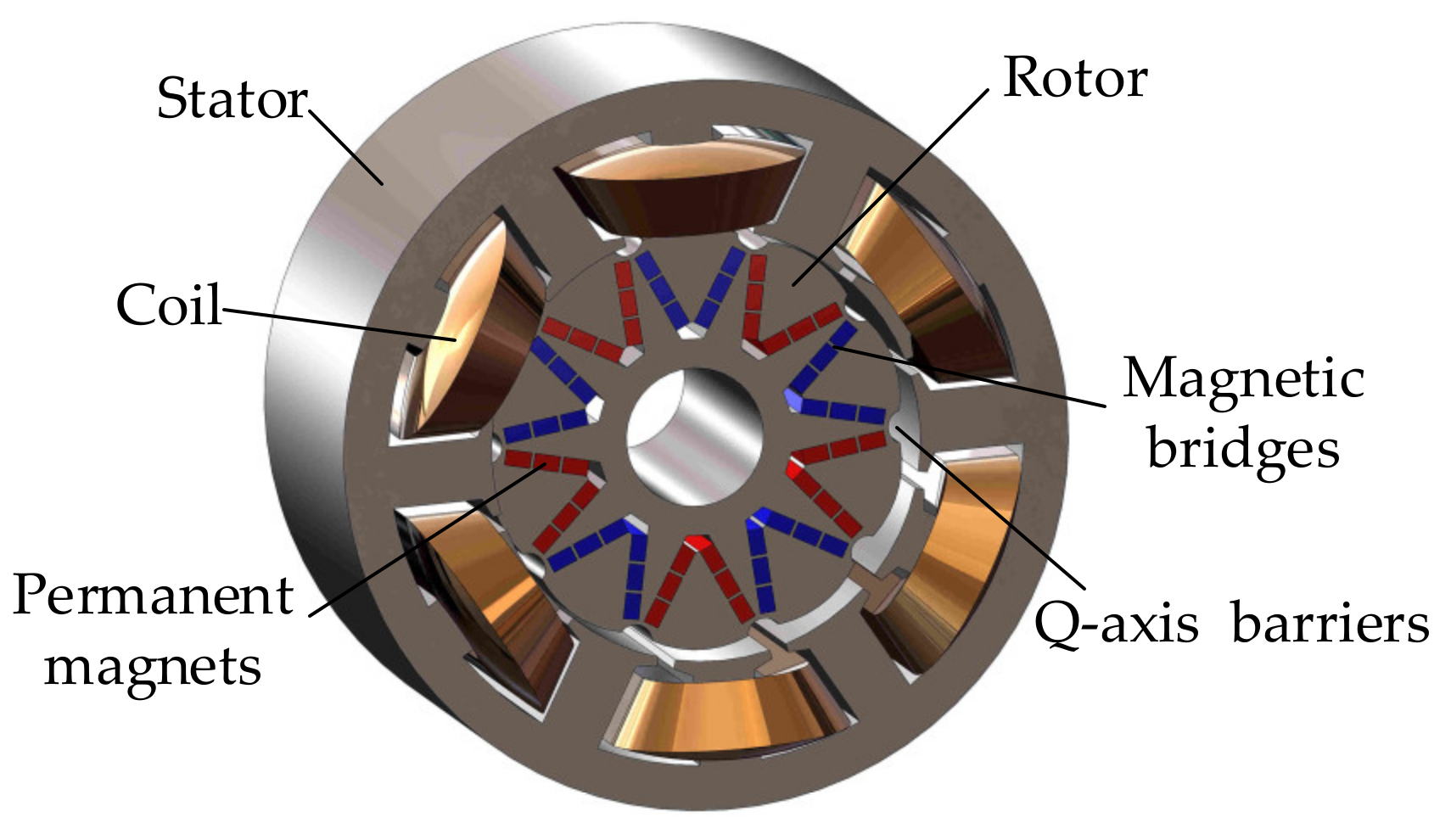
Compared with the conventional IPMSM, the
Ld of an RSPMSM is greater than its
Lq. The structure of the RSPMSM is shown in
Figure 1. The stator is the same as the conventional IPMSM, but the rotor is different. Specifically, on the d-axis, the magnetic bridges and the PMs are connected in parallel to form a “V” shape. The length of the magnetic bridge is larger, and the thickness of the PM is thinner than that of the conventional IPMSM. The magnetic bridges increase the d-axis inductance
Ld, namely, the smaller d-axis flux weakening (FW) current is required for the same FW flux. Thus, the magnetic field adjustment of the RSPMSM is easier. On the q-axis, the arc-shaped magnetic barriers are set to decrease the q-axis inductance
Lq. The outer edge of the rotor is petal-shaped, and thus, the air gap is non-uniform. The air gap gradually increases from the d-axis to the q-axis. Upon completion of the above execution, the RSPMSM is proposed.
To show the relationship between
Ld and
Lq, the saliency ratio
ρ is expressed as in Equation (1).
The ρ values corresponding to the RSPMSM and conventional IPMSM are less than 1 and greater than 1, respectively. We usually realize reverse-salient characteristics through increasing Ld, but the increase in Ld is limited because the PM is located on the d-axis. If Lq is intentionally decreased to decrease ρ, the motor torque output capacity is expected to decrease. Thus, the ρ value of the RSPMSM should not be excessively small.
2.2. Electromagnetic Torque of the RSPMSM
The electromagnetic torque of the PMSM is shown in Equation (2).
where
Tem is electromagnetic torque,
p is the pole pair number,
id and
iq are d-axis and q-axis currents, and
ψf is PM flux linkage.
The electromagnetic torque can be divided into PM torque and reluctance torque. In all operating states of the PMSM, the value of
iq is always positive, and the PM torque is always the driving torque. However, whether the reluctance torque is the driving torque or braking torque depends on the inductance and current. The relationship between
Ld and
Lq of the RSPMSM is different from that of the conventional IPMSM. Thus, the reluctance torque is different; the torque of the two motors is shown in
Figure 2.
Tpm and
Trel are PM torque and reluctance torque, respectively. When the phase of the current lags behind the no-load back-EMF, the value of the internal power factor angle is negative. For conventional IPMSM, when the value of the internal power factor angle is negative, the reluctance torque is the braking torque, and when the value of the internal power factor angle is positive, the reluctance torque is the driving torque.
Consequently, the maximum value of the electromagnetic torque Tem corresponds to a positive internal power factor angle. In contrast, for RSPMSM, when the value of the internal power factor angle is negative, the reluctance torque is the driving torque. The maximum value of the electromagnetic torque Tem corresponds to a negative internal power factor angle. Thus, to use reluctance torque, the RSPMSM exhibits different current control laws.
2.3. Current Control Laws of the RSPMSM
The
Ld of an RSPMSM is greater than
Lq. To use reluctance torque, the value of
id is positive at or below the rated speed, and
id strengthens the permanent magnetic field. The maximum torque per ampere (MTPA) curve lies in the first quadrant, as shown in
Figure 3, where ω1, ω2 and ω3 are angular velocities. For the RSPMSM, the long axis of the voltage limit ellipse is parallel to the
iq axis. The intersection point A of the MTPA curve, the current limit circle, and the voltage limit ellipse lies in the first quadrant. As the speed increases, the current vector gradually moves from points A to A
1, and the magnitude of the flux-intensifying current
id gradually decreases to zero. At point A
1,
id is neither in the flux-intensifying state nor in the FW state. As the speed continues to increase, the current vector gradually moves from points A
1 to B. At this time, the RSPMSM adopts the FW control strategy, where
id is the FW current. When the current vector moves from points B to C, the RSPMSM adopts the maximum torque per voltage (MTPV) control strategy. Notably, when the limit current is less than the characteristic current, the motor can only operate in the MTPA and FW state. For the conventional IPMSM,
id always exhibits an FW effect.
Although both the conventional IPMSM and RSPMSM adopt MTPA, FW, and MTPV control strategies as the speed increases, the directions of the magnetic field generated by id are different. The id of the conventional IPMSM always corresponds to the FW currents. In contrast, the id of the RSPMSM is the flux-intensifying currents at or below the rated speed. As the speed increases, id changes from the flux-intensifying currents to the FW currents, and the FW currents only exist at high-speed. The internal power factor angle adjustment range of an RSPMSM is wider than that of a conventional IPMSM. Thus, the RSPMSM has a wide constant-power speed range speed.
To represent the speed range
k, the relationship between back-EMF and main magnetic flux is studied. When the winding resistance and leakage reactance are ignored, the terminal voltage is equal to the back-EMF, as shown in Equation (3).
where
U is the terminal voltage,
E is the back-EMF,
f is the frequency,
N is the total number of each phase series winding turns,
kw is the winding factor, and
Φδ is the main magnetic flux.
For a PMSM,
N and
kw are constants. The terminal voltage is proportional to the speed. When the PMSM operates at a low speed, the terminal voltage is lower than the limit voltage. As the speed increases, the terminal voltage increases linearly with the speed. Limited by the capacity of the inverter, when the motor terminal voltage reaches the limit value, that is, when the PMSM is operating at point A in
Figure 3, other measures must be taken to ensure that the terminal voltage does not exceed the limit voltage. Equation (3) shows that when the terminal voltage is equal to the limit value, the speed can only be increased by reducing the main magnetic flux.
The variation of the main magnetic flux represents the speed adjustment ability of the PMSM. When the speed remains constant, the back-EMF is proportional to the main magnetic flux; thus, the variation of the back-EMF represents the variation of the main magnetic flux. When the PMSM is operating at point A, the back-EMF is
Emax. When all the components of the current are the FW currents
id, the back-EMF is
Emin. The speed range
k is defined as in Equation (4).
Notably, k can only be used as the basis for judging the constant-power speed range, not the actual speed range; the speed cannot be infinite due to the existence of back-EMF harmonics, motor mechanical strength limitations, and inverter switching frequency limitations.
3. Optimization Design of the RSPMSM
It is of great significance to widen the constant-power speed range and increase the torque of the RSPMSM. In the conventional IPMSM design process, the torque, constant-power speed range, and saliency ratio are not directly considered; thus, the conventional IPMSM design methods are not suitable for accurately designing the RSPMSM. In this paper, according to the relationship between the constant-power speed range, torque, saliency ratio, and motor parameters, the constant-power speed range and torque are directly considered in motor optimization design as the fitness functions. The design requirements of the RSPMSM are shown in
Table 1. The materials of the RSPMSM are shown in
Table 2.
The optimization design flowchart for the RSPMSM is shown in
Figure 4. The process is divided into eight steps. First, according to the application of the RSPMSM, the motor design requirements are entered. Second, the main dimensions are calculated according to the requirements of the motor. Third, according to the rotor design method of the RSPMSM, measurements are taken on the d-axis and q-axis, respectively. A reasonable winding type is simultaneously selected. Upon completion of the above execution, the initial motor model is established. Fourth, it is determined whether the RSPMSM parameters meet the saliency ratio requirements. If not, the dimensions of the RSPMSM are re-determined. If the requirements are satisfied, the RSPMSM dimensions are further optimized. Fifth, the multi-objective optimization of the motor is conducted through genetic algorithm (GA) with the
Tem and
k as fitness functions,
ρ < 1 as a constraint, and the dimensions of the rotor shape and PMs as optimization variables. Specifically, the significant factors are identified through fractional factorial experiments. The fitness function is obtained using the response surface method (RSM). Through GA optimization, the Pareto front is obtained, and the final dimensions of the RSPMSM are determined. Sixth, it is determined whether the optimized motor meets the design requirements in
Table 1. If not, the dimensions of the RSPMSM are re-determined. If the requirements are satisfied, the next step is executed. Seventh, the electromagnetic characteristics of the initial motor and the optimized motor are compared and analyzed. Finally, a prototype is manufactured and tested to verify the characteristics of the RSPMSM.
3.1. Initial Model
The main dimensions are shown in Equation (5). According to the requirement indices for the RSPMSM, the main dimensions are determined. With reference to the design methods of the q-axis magnetic barriers and d-axis PMs of the RSPMSM, an initial motor model is established.
where
D is the inner diameter of the stator,
lef is the stack length,
P is the rated power,
αp is the calculated pole-arc coefficient,
kNm is the waveform factor of the air-gap flux,
kdp is the winding factor,
n is the rated speed,
A is the electrical load, and
Bδ is the maximum value of the air-gap flux density.
The inductance is a critical parameter that affects the constant-power speed range of the motors. The inductance of the motors with different winding types is considerably different. The research on the influence of different winding types on the performance of the PMSM has indicated that a PMSM with a fractional slot concentrated winding has a stronger FW capability than that for a PMSM with an integral slot winding. Under the same conditions, the d-axis inductance of a single-layer fractional-slot concentrated-winding PMSM is larger than that of a double-layer fractional-slot concentrated-winding PMSM [
22]. In this paper, the RSPMSM adopts a single-layer concentrated winding.
The initial dimensions of the RSPMSM are shown in
Table 3. The non-uniform air gap barriers are set at the q-axis. The PMs and soft magnetic materials are alternately arranged in a V-shaped on the d-axis to ensure that
Lq decreases and
Ld increases. Finally, an RSPMSM with
ρ less than 1 is constructed, and the initial motor model parameters meet the requirement that the constant-power speed range is greater than 5:1.
3.2. Identify the Significant Factors
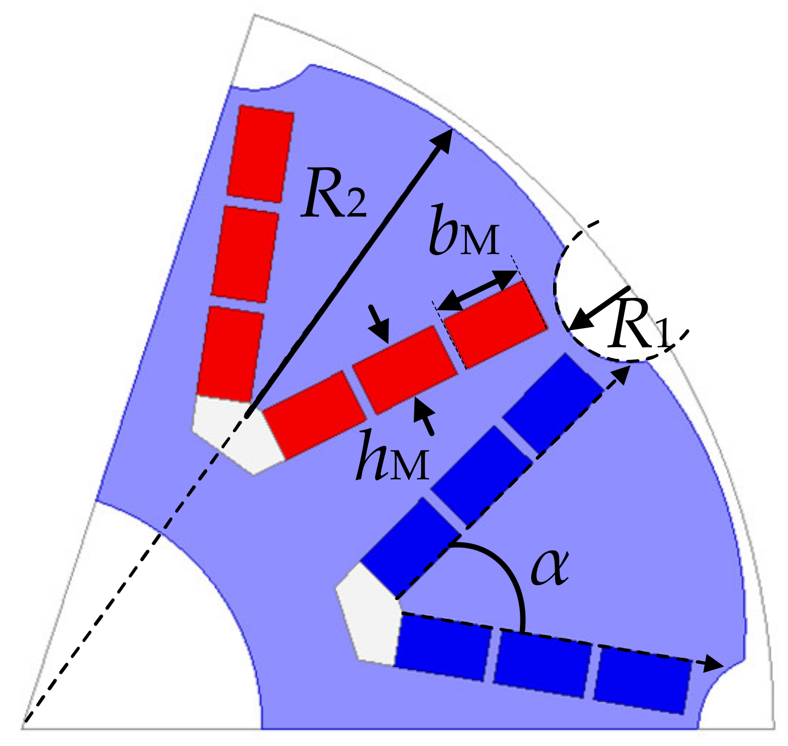
The determination of the shape and dimensions of the rotor is a key step in the design of an RSPMSM. The definition of each parameter of the rotor is shown in
Figure 5. Five variables exist, specifically, the outer edge dimensions of rotors
R1 and
R2, the length of each segment PM
bM, the thickness of the PM
hM, and the angle of the V-shaped PM
α. If each variable takes two values, 32 experiments are required, making it difficult to screen the significant factors. In contrast, the significant factors can be screened by conducting fewer fractional factorial experiments. This paper analyzes the significant factors by using Minitab software (
https://www.minitab.com/zh-cn/, accessed on 9 February 2022). The constant-power speed range
k and electromagnetic torque
Tem are the responses.
Pareto charts and normal plots can be used to statistically analyze and screen the significant factors. The Pareto chart shows the absolute value of the standardized effect, as shown in the
Figure 6a,c, in which the red dotted line is the reference line, and the standardized effect exceeding the reference line indicates that the factor is statistically significant. When analyzing the factorial design, the order of the items included in the model is set as two. The terms include first-order and second-order terms, among which the second-order terms only contain two items, BE and BC, indicating that other second-order terms do not influence the responses. The standardized effects of E, B, and C exceed the reference line, indicating that E, B, and C are statistically significant. The normal effect plot can reflect the magnitude, direction, and importance of the effect, as shown in
Figure 6b,d. A value farther from 0 corresponds to a more statistically significant effect. Consequently, E, B, and C are significant factors, where E corresponds to a positive normalization effect, indicating that the responses increase when the value of the factor increases. B and C correspond to negative normalization effects, indicating that the responses decrease when the factor value increases. The significant factors are shown in
Table 4.
3.3. Multi-Objective Optimization
Through the screening of significant factors, we see that the rotor outer dimension R2, the angle of the V-shaped PM α, and the PM length bM are significant factors, and thus, they are selected as optimization variables. In the process of optimization design, the reverse-salient characteristic of the motor should always be maintained, so the saliency ratio is taken as the constraint. To obtain an RSPMSM with a large torque at low-speed and a wide constant-power speed range at high-speed, the torque and constant-power speed range are taken as the optimization objectives, respectively.
The process of multi-objective optimization can be divided into the following steps: First, determine the optimization variable range using the rotor space constraints, mechanical strength constraints, and initial electromagnetic analysis. The range of the optimization variables is shown in Equation (6). Second, set
ρ < 1 as a constraint. The constraint is shown in Equation (7). Third, establish fitness functions. The relationships between the significant factors and the responses are obtained using the RSM. Using the central composite design method, the response values
k and
Tem are obtained using the FEM.
k and
Tem are expressed in Equation (8). Fourth, compile a GA algorithm calculation program, substituting the optimization variables, constraints, and fitness functions.
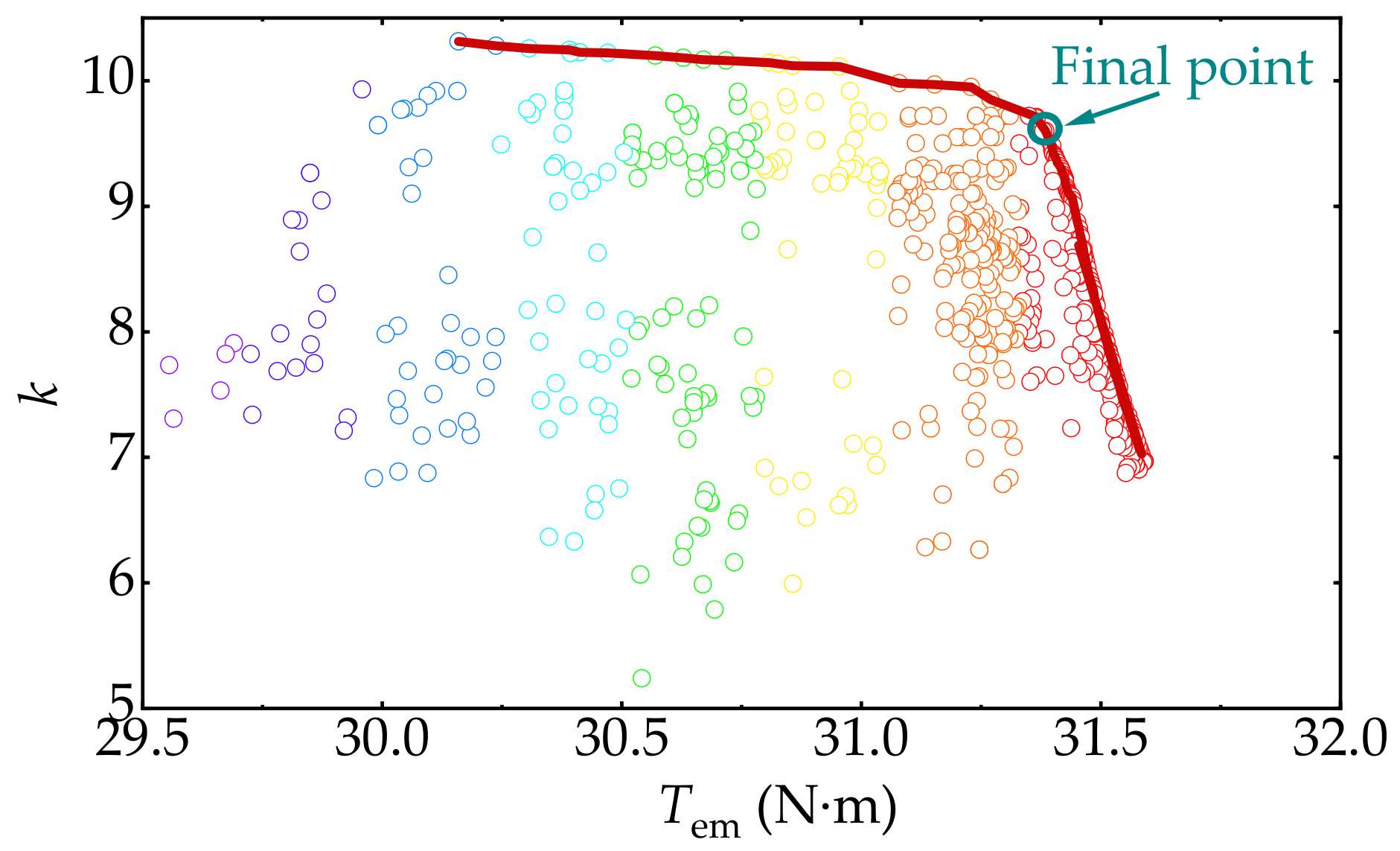
The algorithm parameters are set as follows: the initial population size is 300, the number of iterations is 200, the crossover probability is 0.8, and the mutation probability is 0.5. The Pareto front and partial solutions are shown in
Figure 7. After comprehensive consideration, the final point of the RSPMSM is chosen.
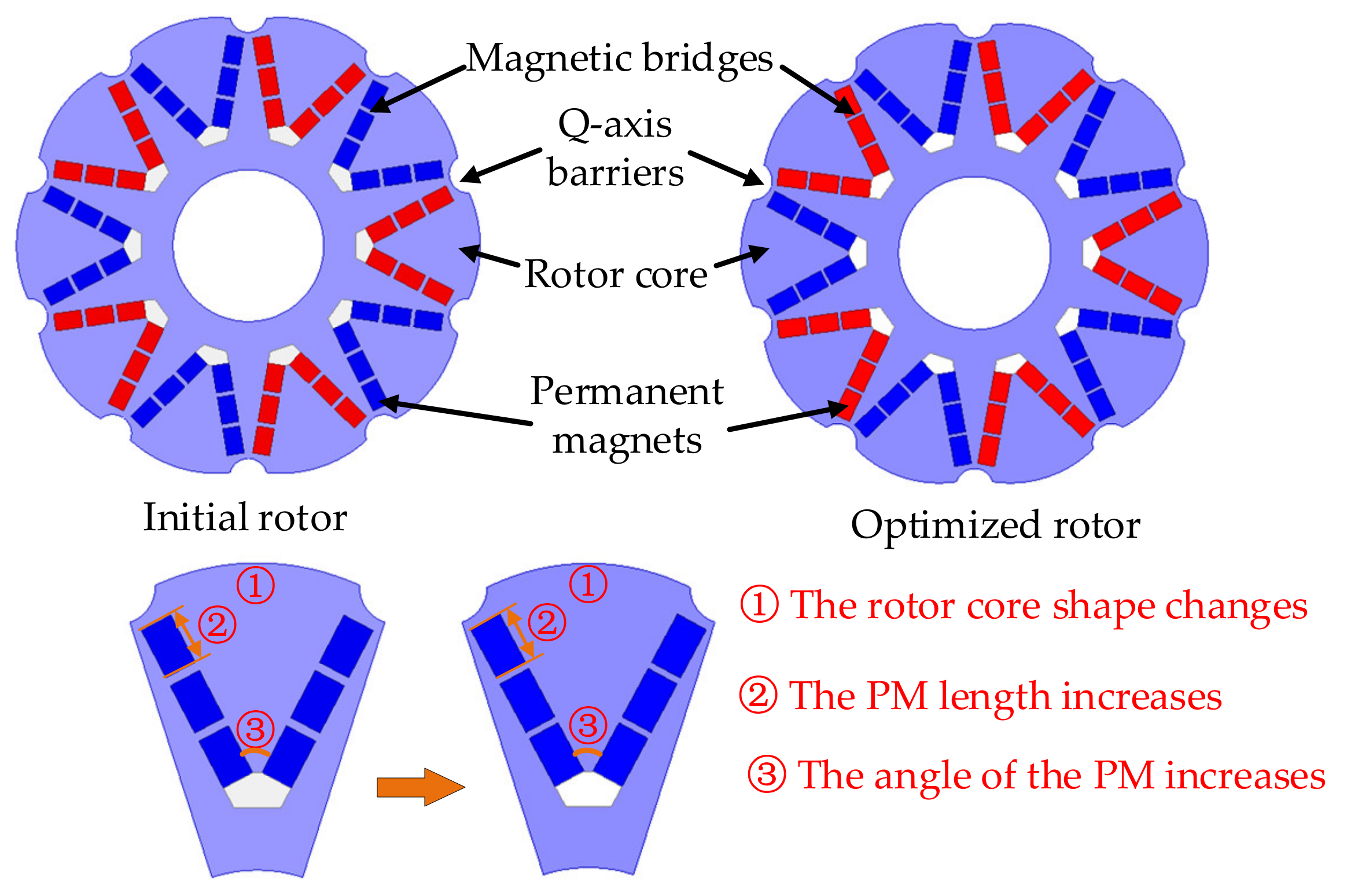
The optimization variable values corresponding to the final point are shown in
Table 5. The initial rotor and optimized rotor of the RSPMSM are shown in
Figure 8. After optimization, the changes of the rotor mainly include the following three aspects: First, the rotor shape changes. Second, the PM length is increased. Third, the angle of the PM increases. Although the rotor is changed slightly, the torque and constant-power speed range of the RSPMSM has been significantly improved, which will be analyzed in
Section 4.
5. Experimental Verification
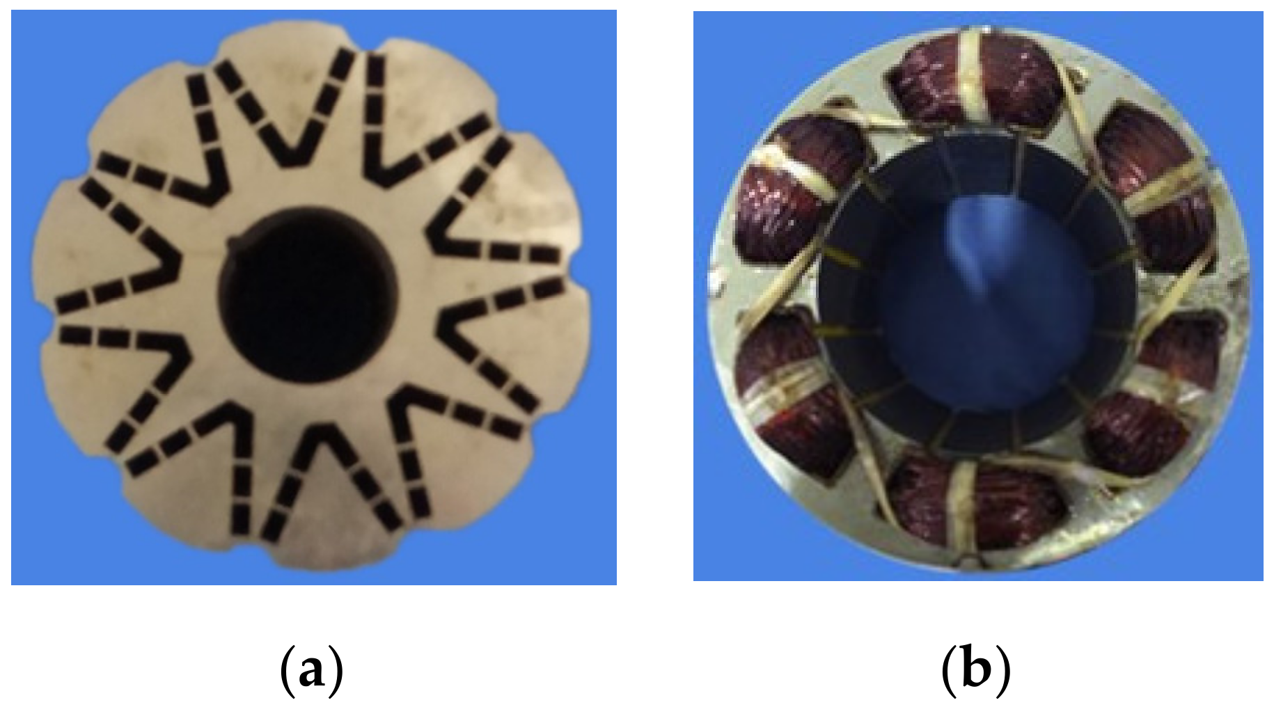
A prototype is manufactured for verification. The rotor and stator cores are machined by wire cutting. The RSPMSM adopts a single-layer concentrated winding. The rotor core and stator are shown in
Figure 15.
The experimental platform is shown in
Figure 16. A Lenze 9400 servo drive (
https://www.lenze.cn/en-cn/, accessed on 9 February 2022) is used to drive and control the RSPMSM, a Magtrol dynamometer (
https://www.magtrol.com, accessed on 9 February 2022) is used to provide the load torque. A Tamagawa resolver (
https://www.tamagawa-seiki.com/, accessed on 9 February 2022) is installed on the shaft behind the rear end cover. The Lenze drive reads the rotor position through the Tamagawa resolver. The voltage and current limits are set to 220 V and 8.95 A, respectively. A power analyzer is connected between the prototype and the Lenze drive to record the actual voltage, current, speed, torque, etc.
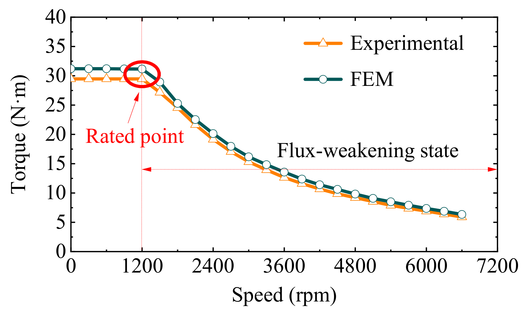
The torque-speed and power-speed curves of the RSPMSM are shown in
Figure 17 and
Figure 18, respectively. The RSPMSM meets the requirements for a large torque output in the low-speed area and a wide constant-power speed range in the high-speed area. The experimental value of the torque is 29.7 N·m, 5.4% lower than the simulation result. The main reason for the error is that the simulated torque is the electromagnetic torque, and the experimentally measured torque is the actual output torque, which refers to the difference in the electromagnetic torque and the no-load torque. Limited by the switching frequency of the Lenze 9400 driver, the measured maximum speed is 5.5 times the rated speed. The trends of the torque-speed and power-speed curves measured in the experiment are consistent with those observed in the simulation. These findings verify the wide constant-power speed range of the RSPMSM.


