Article

Discussion on Ball Screw Slide–Roll Ratio and Entrainment Velocity Calculation

1
Key Laboratory of High-Efficiency and Clean Mechanical Manufacture, Ministry of Education, School of Mechanical Engineering, Shandong University, Jinan 250061, China
2
National Demonstration Center for Experimental Mechanical Engineering Education, Shandong University, Jinan 250061, China
*
Author to whom correspondence should be addressed.
Machines 2022, 10(3), 203; https://doi.org/10.3390/machines10030203
Submission received: 2 February 2022 / Revised: 8 March 2022 / Accepted: 9 March 2022 / Published: 11 March 2022
(This article belongs to the Special Issue Kinematics and Dynamics of Mechanisms and Machines)

Abstract

:
The slide–roll ratio and entrainment velocity are critical parameters in ball screw mechanism tribology investigations and are often determined by Chin-Chung Wei’s approach. Their findings indicated that substantial sliding always occurs between the ball and the raceways, which appears to violate the ball drive principle. We validated Wei’s approach using the Harris method, which is widely used in rolling bearing research. When the helix angle is set to zero, significant differences occur: when the Harris method is utilized, the entrainment velocity at the inner contact points is essentially equal to that at the outer contact points, and the slide–roll ratio is zero for both; however, when Wei’s method is utilized, the entrainment velocity at the inner side is nearly three-times that of the outer side, and the slide–roll ratio at the outer side approaches two—the level of pure sliding—which is clearly incorrect. To overcome this issue, we present an accurate approach for obtaining the slide–roll ratio and entrainment velocity for ball screws by regarding the Frenet frame as a virtual cage, which is particularly applicable to those with a long lead and operating at high speeds. Moreover, we investigated the effect of structural factors on the slide–roll ratio and entrainment velocity utilizing this model.

1. Introduction

Ball screw mechanisms (BSMs) are a common type of component used in machine tools to convert motor rotations into linear motions. As with ball bearings, it employs several bearing balls to decrease friction, resulting in great positional precision and high conversion efficiency. Due to the helix angle, sliding motion is constantly present in the contact region, resulting in heat effects and limiting the operational range of the component [1,2]. In practice, high-speed ball screws are lubricated with oil to decrease friction. Since the contact between the ball and the raceway is considered a single point, elastohydrodynamic lubrication (EHL) analyses are often performed in BSM lubrication investigations. The entrainment velocity is a significant parameter in EHL analysis that is utilized to characterize the movement of the contact surfaces. It is essential to properly solve for the entrainment velocity while examining the lubricating status of the ball–race contact region.
Due to the closed structure of BSMs, it is hard to obtain the balls’ kinematic properties through experiments. Lin et al. [3] proposed a theoretical method in 1994 for describing the motion of the balls by constructing a Frenet frame. They developed a method for determining the slip velocities at the contact points. Based on Lin’s study, Wei et al. [1] derived the angular velocities of the balls while considering the influence of elastic deformation, then further analyzed how structural factors affect the friction behavior and mechanical efficiency of the BSM. The preceding studies established an efficient method for determining the linear velocities of BSMs, which were applied in multiple studies [4,5,6]. Wei et al. [7] performed a kinematic analysis of two balls and analyzed the BSM’s mechanical efficiency and slipping–rolling behavior for a preloaded single-nut double-cycle ball screw. Hu et al. [8] investigated the kinematic characteristics of a BSM utilizing the homogeneous transformation matrix and the influence of movement velocity on the slide–roll ratio. Previous studies established a basis for determining the contact surface velocities, but their results suggested that significant sliding between balls and raceways always occurs, which appears to conflict with the ball screws’ operating principle. Meanwhile, their findings indicated a considerable disparity in the entrainment velocities between ball–nut and ball–screw contact, which may not be an accurate reflection of the motion relationship between the lubricants and the contact surfaces.
The elastic deformations caused by both the contact load and the centrifugal force can affect the velocities of the balls, making the load distribution of BSMs an important consideration in kinematic studies. Wei et al. [1] considered the effect of elastic deformations and determined the contact angles and gyroscopic angles numerically, assuming that all balls were bearing the load uniformly. Mei et al. [9] proposed a static load distribution model for ball screws that included the axial elastic deformations between the balls, indicating that the load distribution curve is monotonous and concave. For ball screws with geometric errors, Lin et al. [10] proposed a low-order FE model to predict the static load distribution and proved that manufacturing inaccuracies can have a significant effect on the load distribution. Zhen et al. [11] and Zhao et al. [12] considered radial elastic deformations in their studies and further determined the contact load of balls during operation, showing that the contact load is location-dependent. Additionally, Liu et al. [13] proposed a method for determining the load distribution caused by the nut’s location. Previous studies have shown that the contact angles of balls under static conditions are slightly different among the balls. Meanwhile, the centrifugal force derived from kinematic studies is also essential in improving these models for high-speed ball screws.
Several EHL studies on ball screws have been published in the last few decades. Wei et al. [14] investigated the impact of lubrication during mechanical efficiency analysis by approximating the hydrodynamic pressure with the Hertzian contact pressure. Mu Shigang [5] determined the kinematic parameters and analyzed the EHL behavior of a nut-driven high-speed ball screw. Zhang et al. [15] conducted experiments to compare the lubricating effects of oil and grease. Several studies [16,17] have used laser surface texturing to enhance the tribological performance of ball screws in recent years. Entrainment velocity plays a critical part in nearly all of these EHL investigations. A large amount of research agrees that the entrainment velocity at the screw side is similar to that at the nut side, as the experiments demonstrated, but merely estimating it using absolute velocities derived by Wei’s model [1] results in a large discrepancy at the two sides.
Ball bearing research is highly relevant due to the resemblance between ball screws and ball bearings. In the 1970s, Harris [18,19] developed an analytical approach for determining the motion of ball bearings. Additionally, he incorporated fundamental theories for rolling bearings in a book [20], which has been widely utilized in subsequent research. Meng et al. [21] recently proposed a multi-ellipsoid contact elastohydrodynamic lubrication model for deep groove ball bearings that takes into account the skidding phenomena, as well as the interactions between the bearing’s various components. These ball bearing studies demonstrated an efficient method for calculating entrainment velocities using relative rational speeds to the cage.
The Frenet frame affixed to the balls in a ball screw performs a similar function to the cage in ball bearings. In this work, we suggest a novel approach for calculating the slide–roll ratio and entrainment velocity based on the relative velocities, which can be utilized to precisely compare the behavior at the nut or screw side, which is particularly crucial for ball screws with a long lead and operating at high speeds. We determined the relative velocities of the ball screw’s contact surfaces by treating the Frenet frame as a virtual cage. We also introduced a different method for obtaining absolute and convected velocities to address several issues in the earlier models. Furthermore, we also looked at the impact of the BSM’s structural factors.

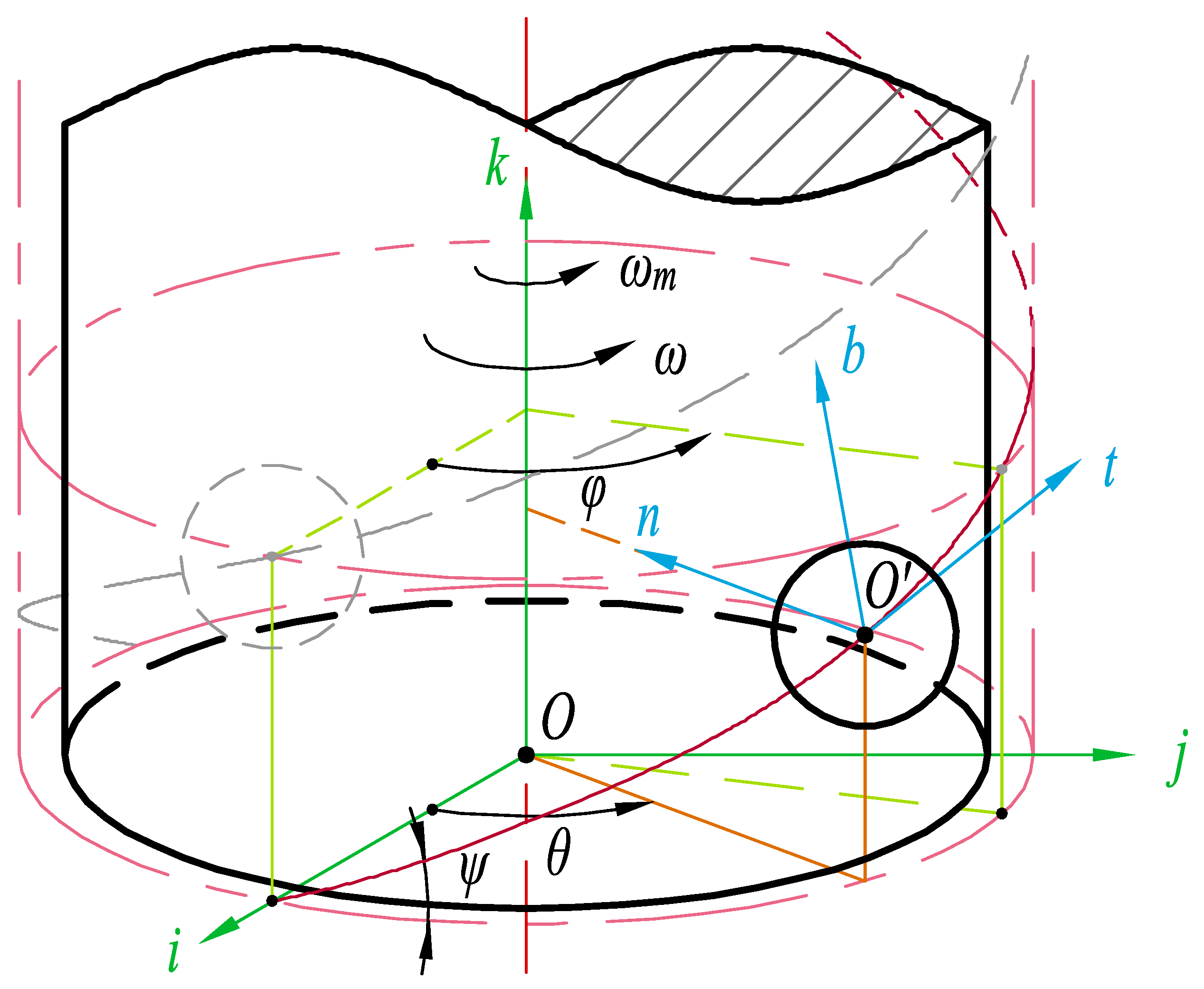
2. Theoretical Analysis

2.1. Slide–Roll Ratio and Entrainment Velocity

Entrainment velocity U is defined as the average of the linear velocities of the two surfaces to evaluate the motion at the contact point. In elastohydrodynamic lubrication analyses, it is used to determine the dimensionless velocity parameter in the Hamrock–Dowson oil film thickness equation [22,23,24]. Additionally, it is also a critical component when evaluating the thickness and pressure distribution of EHL films.
The rotating speeds of ball bearing elements are often transformed into relative velocities relative to the cage in its EHL studies [20,21], and the resulting entrainment velocities at the inner and outer rings’ contact points are practically identical. Considering the structural similarities between the BSM and rolling bearings, as well as the Frenet frame’s role as a virtual cage, we determined the entrainment velocity and slide–roll ratio using the linear velocity relative to the Frenet coordinate system. The following formulas were used to determine the entrainment velocity at the contact point for a BSM:
U A = 1 2 | V A n r + V A b r |
U B = 1 2 | V B s r + V B b r |
where V A n r and V B s r are the nut/screw’s relative linear velocities at the contact point and V A b r and V B b r are the ball’s relative linear velocities at the contact point of the nut and the screw side.
The slide–roll ratio is a frequently used indicator for evaluating contact surface sliding behavior. It is defined as the ratio of two surfaces’ sliding velocities to their average velocities:
S = 2 ( v 1 v 2 ) v 1 + v 2
where v 1 and v 2 are the linear velocities of the driven and passive surfaces, respectively. When S = 0 , pure rolling occurs between the two surfaces; pure sliding occurs when S = ± 2 . From Equations (1)–(3), the slide–roll ratio can also be considered as the ratio of the sliding velocity to the entrainment velocity. In the case of a BSM, the slide–roll ratio at the contact point between the ball and raceways can be obtained by:
S ζ = | V S ζ | U ζ , ζ = A , B
where ζ = A or ζ = B represents the contact point between the ball and the nut/screw raceway, respectively; the sliding velocity is defined as:
V S A = V A b r V A n r
V S B = V B s r V B b r

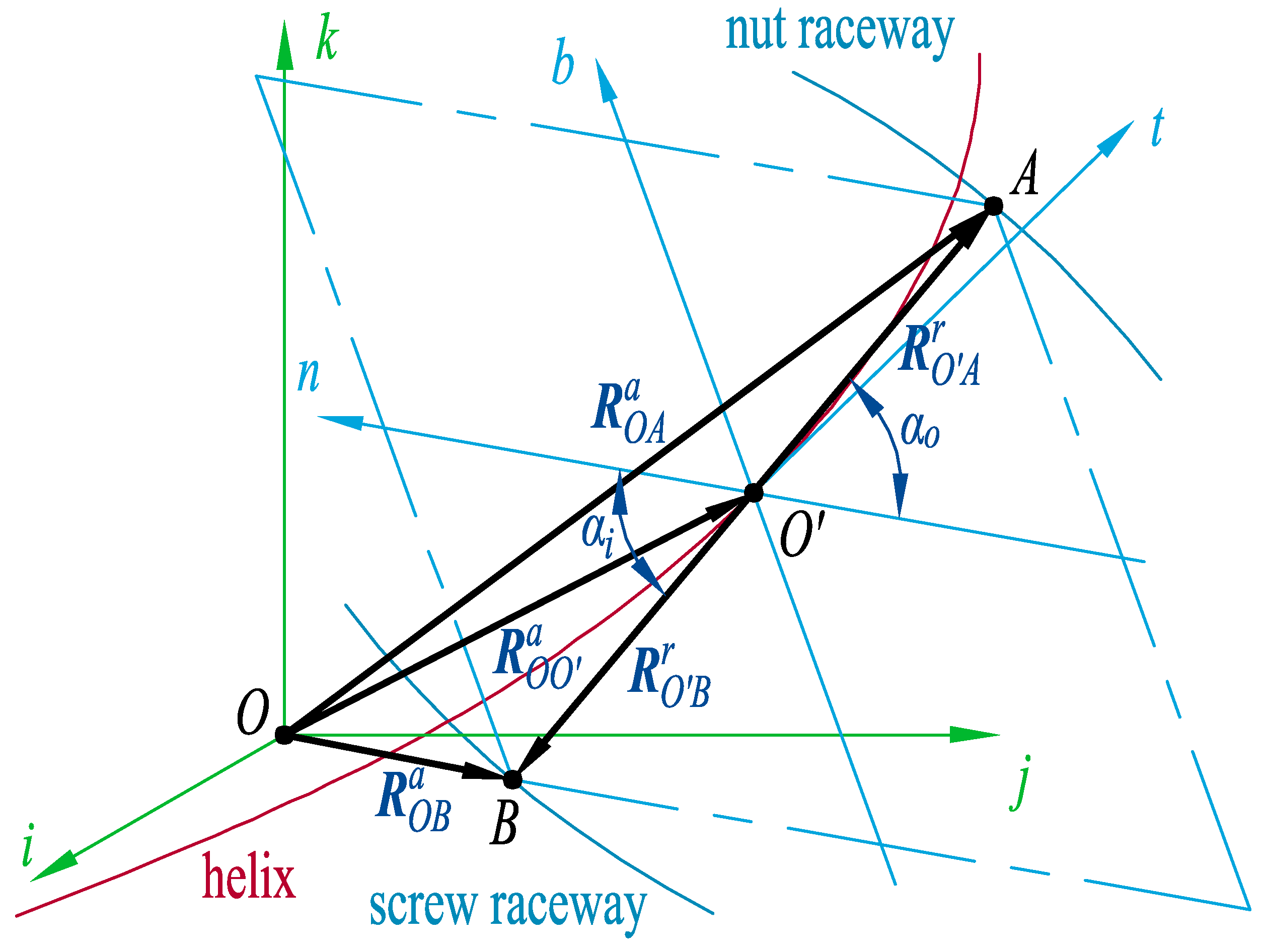
2.2. Position of Contact Points

In a ball screw mechanism, a global coordinate system and a Frenet coordinate system are created to uniformly express the velocity of the contact surfaces. As seen in Figure 1, the global coordinate system CS 0 was fixed to the base, with its origin at O and its k-axis aligned with the screw’s axis. CS 0 ’s base vector is defined as:
X = i j k T
where i , j , and k are the unit vectors of the i-axis, j-axis, and k-axis, respectively. Notably, all vectors ending in X were measured in the global coordinate system CS 0 . The location of each ball is defined by its azimuth θ in combination with the screw’s rotation angle ϕ . Since the contact point is always in the normal section of the raceway, we define a Frenet coordinate system CS 1 with its origin O fixed at the ball center, its t-axis pointing in the positive direction of the k-axis along the helix and its n-axis pointing in the radial direction to the screw axis center. Y is the Frenet coordinate system’s basic vector, defined as:
Y = t n b T
where t , n , and b are the unit vectors of the t-axis, n-axis, and b-axis, respectively. Notably, all vectors ending in Y were measured in the Frenet coordinate system CS 1 . Transformations between the two coordinate systems can be expressed as follows:
X = T 1 Y
Y = T 1 1 X
the coordinate transformation matrix can be determined by:
T 1 = cos ψ sin θ cos θ sin ψ sin θ cos ψ cos θ sin θ sin ψ cos θ sin ψ 0 cos ψ
where ψ is the helix angle of the raceway.
Suppose that the ball screw is supported by a fixed floating type and that the nut’s downside is pulled downward. Figure 2 shows the contact point location vectors, where A and B represent the ball’s contact points with the nut and screw raceways, respectively. The absolute position of the ball center in the global coordinate system CS 0 can be written as:
R O O a = r m cos θ r m sin θ L θ ϕ 2 π X
where r m and L are the BSM’s nominal diameter and lead, respectively. The vector from the ball’s center to the nut’s and screw’s contact point can be expressed as:
R O A r = 0 r b cos α o r b sin α o Y
R O B r = 0 r b cos α o r b sin α o Y
where r b is the ball’s diameter and α o and α i are the contact angle of the ball–nut contact and ball–screw contact. The superscripts a and r in the above equations indicate whether the vector is related to the fixed global coordinate system, CS 0 , or the moving Frenet coordinate system, CS 1 .
Through the conversion of the vectors in Equations (11) and (12) into global coordinates with the help of Equation (8), then incorporating them into Equation (10), the two contact points’ absolute coordinates can be determined:
R O A a = r m cos θ + r b ( cos α o cos θ + sin α o sin θ sin ψ ) r m sin θ + r b ( cos α o sin θ sin α o cos θ sin ψ ) ( θ ϕ ) L 2 π + r b sin α o cos ψ T X
R O B a = r m cos θ r b ( cos α i cos θ + sin α i sin θ sin ψ ) r m sin θ r b ( cos α i sin θ sin α i cos θ sin ψ ) ( θ ϕ ) L 2 π r b sin α i cos ψ T X

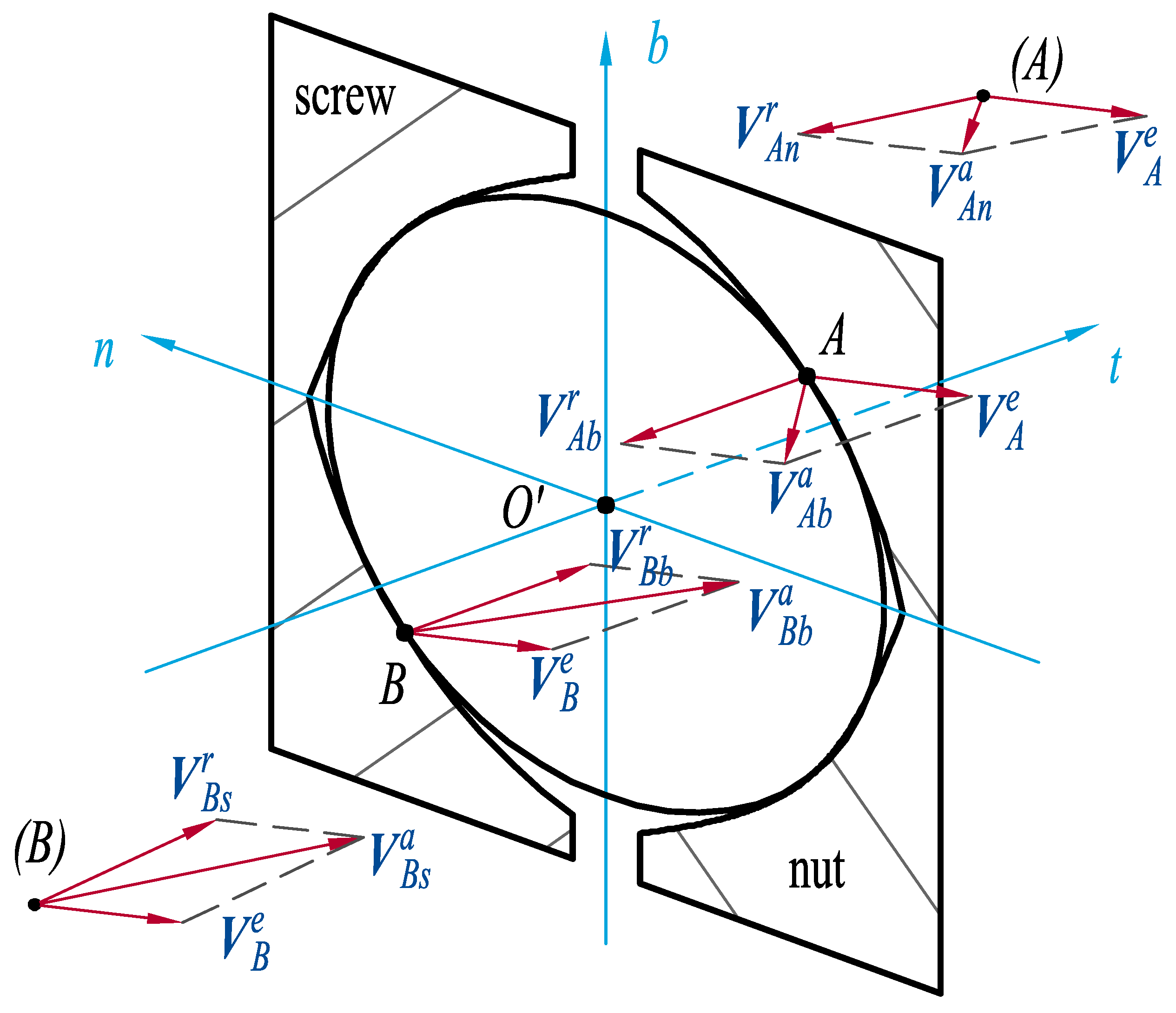
2.3. Absolute Velocity

When represented in the Frenet coordinate system CS 1 , the balls’ velocity vectors are independent of the position angle θ since the balls always travel along the spiral raceway. As a result, this study utilizes the ball with θ = 0 to determine the linear velocities of the contact surfaces and then converts them to CS 1 using Equation (7). The matrix of coordinate transformations Equation (9) can be simplified as follows:
T 1 = 0 1 0 cos ψ 0 sin ψ sin ψ 0 cos ψ
Since the nut can only translate along the screw’s axial direction, the absolute velocity of each point on it is:
V A n a = 0 0 ω L 2 π X = ω L 2 π sin ψ 0 L 2 π cos ψ Y
where ω is the screw’s angular speed of rotation, i.e., ω = ϕ ˙ .
The screw rotates around its axis without axial movement, and the contact point’s absolute velocity is:
V B s a = ω × R O B a = ω r b sin α i sin ψ r m r b cos α i 0 T X = ω ( r m r b cos α i ) cos ψ r b sin α i sin ψ ( r m r b cos α i ) sin ψ T Y
Referring to Wei et al.’s study [1], the orbital speed of the ball ω m ( ω m = θ ˙ ), the ball’s rotation speed along its own axis ω R , and its components along each Frenet coordinate system axis can be determined as follows:
ω m = ω 1 + ( 1 + γ cos α o ) ( cos α i + tan β sin α i ) ( 1 γ cos α i ) ( cos α o + tan β sin α o )
ω R = ω m ( 1 + γ cos α o ) cos ψ γ ( cos β cos α o + sin β sin α o )
ω R = ω t ω n ω b T Y = ω R cos β sin β ω R sin β ω R cos β cos β T Y
where γ = r b / r m , β , and β are the pitch and yaw angles relative to the Frenet frame, respectively. Since the yaw angle β is considerably small [1], it was set to zero in our study. Considering the effect of the ball’s centrifugal force, this study assumed that the nut-side raceway and the ball exhibit just pure rolling, and the pitch angle can be calculated as follows [5]:
β = arctan sin α o cos α o + r b cos α o / r m
Additionally, for high-speed ball screws, the orbital motion of the ball provides centrifugal force in the direction opposite to n (pointing radially outwards). The centrifugal force can be obtained by [1]:
F n = m r m ω m 2
where m is the mass of the ball.
As illustrated in Figure 3, the absolute velocity of a point on the ball V b a can be calculated as the sum of the convected velocity at that point V ζ e and its relative velocity in the Frenet coordinate system V ζ b r , i.e.,:
V A b a = V A e + ω R × R O A r = V A e + r b ( ω n sin α o + ω b cos α o ) ω t r b sin α o ω t r b cos α o T Y
V B b a = V B e + ω R × R O B r = V B e + r b ( ω n sin α i + ω b cos α i ) ω t r b sin α i ω t r b cos α i T Y
It should be noted that in Figure 3, (A) and (B) represent the contact points on the nut and screw raceways, which should be located in the same area as A and B.

2.4. Relative Velocity

Before determining the relative velocities, we should first obtain the convected velocities at the contact points—that is, the absolute velocity of the Frenet frame at the contact points’ corresponding locations. Thanks to the fixed position of the contact point in the Frenet frame, we can derive Equations (13) and (14) (the absolute coordinates of the two contact points A and B) with time and transform the coordinates to obtain the convected velocity at the contact point:
V A e = R ˙ O A a = ω m ( r m + r b cos α o ) cos ψ + ( ω m ω ) L 2 π sin ψ ω m r b sin α o sin ψ ω m ( r m + r b cos α o ) sin ψ + ( ω m ω ) L 2 π cos ψ T Y
V B e = R ˙ O B a = ω m ( r m r b cos α i ) cos ψ + ( ω m ω ) L 2 π sin ψ ω m r b sin α i sin ψ ω m ( r m r b cos α i ) sin ψ + ( ω m ω ) L 2 π cos ψ T Y
By subtracting the convected velocity Equations (25) and (26) from the absolute velocities Equations (16), (17), (23) and (24), the relative velocities of the raceway and ball at the contact point are obtained as follows:
V A n r = V A n a V A e
V A b r = V A b a V A e
V B s r = V B s a V B e
V B b r = V B b a V B e
Finally, substituting the above equations into Equations (1), (2) and (4), the entrainment velocity and slide–roll ratio measured by the relative velocity can be obtained.

3. Results and Discussion

3.1. Verification Based on a Ball Bearing

Since a ball bearing is a particular case of a ball screw, the theory of a ball screw is also applicable to the kinematic analysis of a ball bearing when the lead is set to zero. We calculated the entrainment velocity and slide–roll ratio for the deep-groove ball bearing 61830 from [21] and compared them to the classical Harris approach using the method proposed in this research and the method from [1]. The inner ring of the bearing was set to rotate at 3600 rpm. It should be noted that throughout this study, we assumed constant contact angles between the ball and the inner and outer raceways: α i / o α = π / 4 , neglecting the influence of elastic deformation.
As shown in Table 1, this model obtains identical inner and outer entrainment velocities, which is consistent with the widely used Harris method; however, Wei’s method gives an inner entrainment velocity nearly three-times that of the outer, which may result in an overestimate of the speed difference between the inner and the outer sides. Furthermore, the slide–roll ratio calculated by this proposed model is zero on both the inner and outer sides, indicating that the contact between the ball and the raceway is close to pure rolling; the results obtained by Wei’s model indicated that pure sliding occurs between the ball and the outer raceway and that significant sliding also occurs between the ball and the inner raceway, which is inconsistent with the ball bearing principle.

3.2. BSM-Based Discussion

To further investigate the reasons for the disagreement between the results of this study and those gained from Wei’s model, we compared our results and performed the following analyses using the double-cycle BSM from [1]. Its essential parameters are listed in Table A1. The angular velocities of the ball, the contact angle, and the pitch angle were calculated using the same previous simplification: Equations (18)–(21), and some errors in the original paper were rectified, resulting in acceptable variations between the following results obtained by Wei’s method and the original values in [1]. The kinematic parameters derived using our new approach and Wei’s model are listed in Table 2.
As with the ball bearing case, there is a significant disparity in Table 2 between our model’s and Wei’s entrainment velocity results. The entrainment velocity of a ball screw is defined as the average of two components: the linear velocity of the ball’s surface at the contact point and that of the raceway. Given that we utilized the same angle simplification for both models in this case study, all the absolute velocities should be identical between both of our outcomes, as the absolute velocities for the nut and screw raceways ( V A n a and V B s a ) already proved.
The primary distinction is in the ball’s result: V A b a and V B b a . Our result indicates that the ball shares a similar speed with the raceway at the contact point, causing it to rotate rapidly in the opposite direction of the screw’s rotation; while in Wei’s result, the absolute velocities of the balls on the screw and nut sides were nearly identical, and the velocities had a substantial component in the t-direction, indicating that the balls were almost traveling tangentially along the helix and were not rolling. This phenomenon contradicts both the ball’s real movement and also Wei’s calculation of the ball’s angular velocity, demonstrating that the inconsistencies between our and Wei’s conclusions are largely attributable to our different treatment of linear velocities.
Additionally, even the sliding velocity at the nut was also similar to that of the screw side when Wei’s method was applied; the slide–roll ratio of the two sides remained significantly different, making it inconvenient to directly compare the sliding status of the two sides using the slide–roll ratio obtained from absolute velocities. Given that our procedure with relative velocities does not affect the result of sliding velocity (as demonstrated by Equations (5), (6) and (27)–(30)), the sliding velocities obtained in both ways should be identical, allowing us to evaluate the sliding velocity based on relative velocities as well. Since we proved that entrainment velocities are similar to sliding velocities and can be used as a more proper reference for the sliding velocity when calculating with relative velocities (which is also a widely used method in ball bearing research), calculating the slide–roll ratio using relative velocities provides an unambiguous comparison of the sliding behavior on the screw and nut sides.

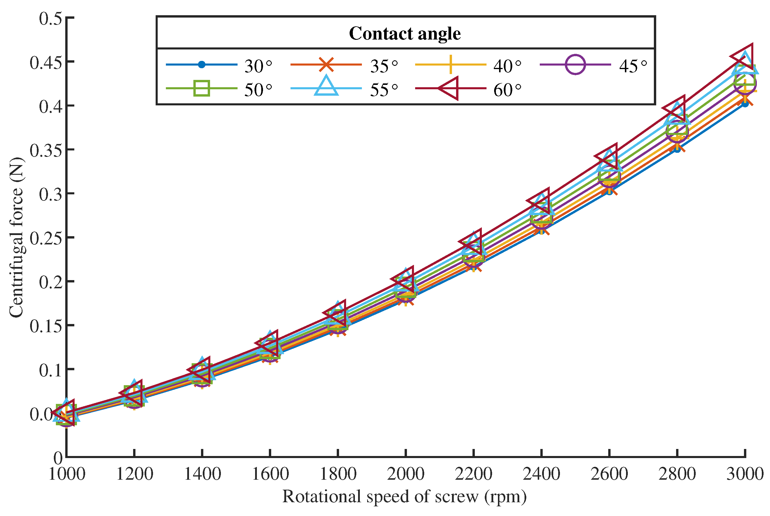
3.3. Centrifugal Force

The centrifugal force generated by the rotation of the ball alters the load distribution and also the contact angle. As shown in Equation (22), the centrifugal force of the ball is directly proportional to its mass and nominal diameter, as well as to the square of its angular velocity of rotation. Additionally, it was determined from Equation (18) that the change in contact angle impacts the centrifugal force.
The trend of centrifugal force as a function of screw rational speed and contact angle in Figure 4 demonstrates that the centrifugal force on the ball is nearly constant for different contact angles and that increasing the rotational speed greatly increases the centrifugal force. When the axial load was 1000 N, the average contact load on the ball was approximately 27 N; even when the screw rational speed was 3000 rpm, the centrifugal force on the ball was only about 2% of the contact load. As a result, the centrifugal force had a negligible effect on lubrication for ball screws running at medium to high speeds. This finding also reveals that it is appropriate to assume that the inner and outer contact angles are equal. Since the centrifugal force is insensitive to contact angle changes, the result measured at the nominal contact angle can be employed as a known constant in investigations considering centrifugal force.

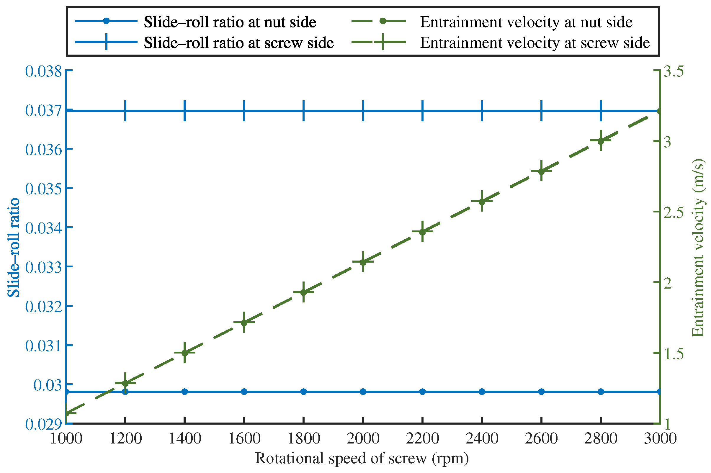
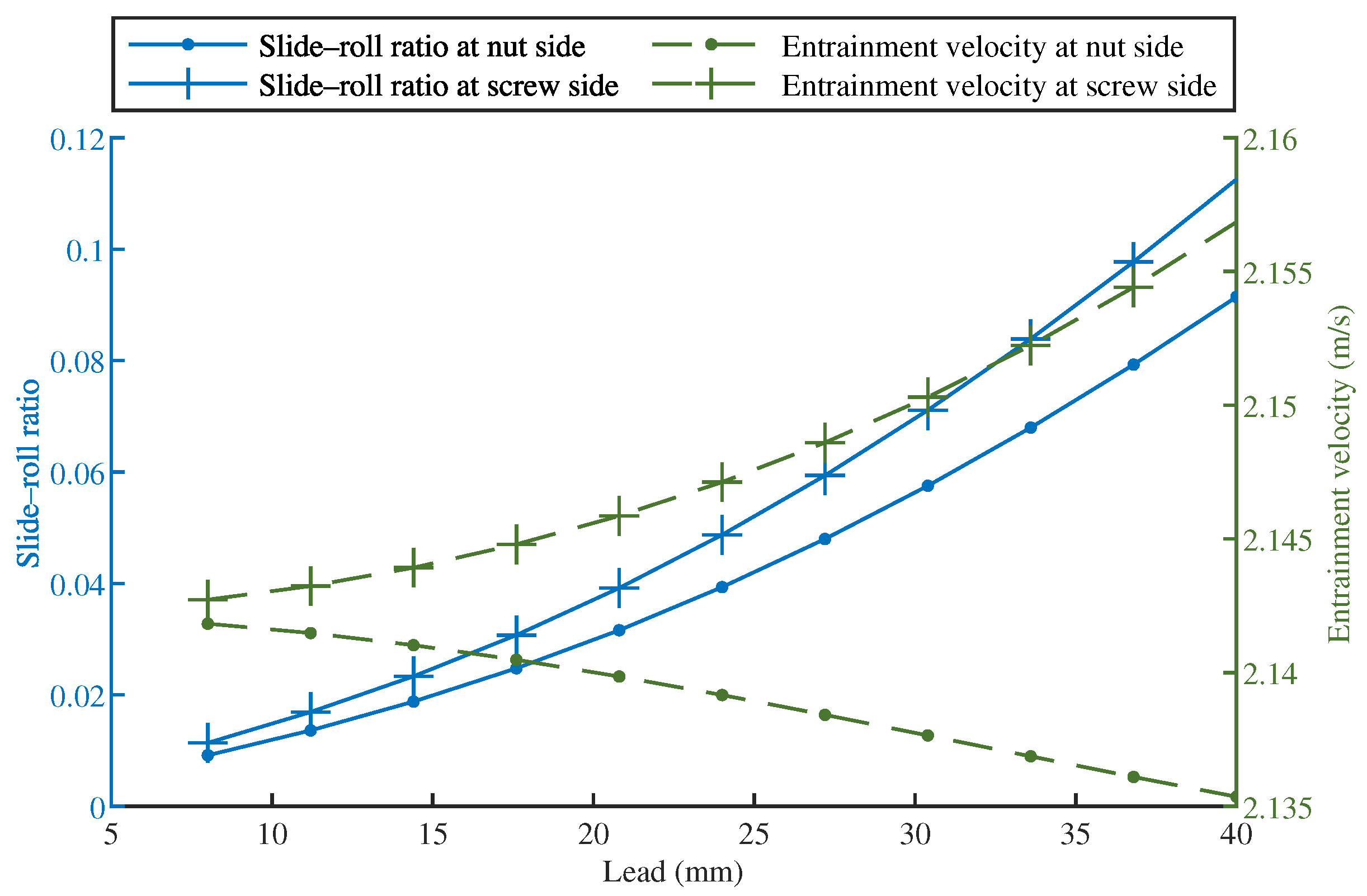
3.4. Slide–Roll Ratio and Entrainment Velocity

3.4.1. Effect of Screw Rotational Speed

The rotation speed of the screw has a significant impact on the entrainment velocity. As seen in Figure 5, the entrainment velocity is fairly similar on the screw and nut sides and increases linearly with increasing speed. This was mostly due to the rise in the contact point’s relative velocity. The slide–roll ratio is independent of the screw rational speed as defined in Equations (4), (18)–(20) and (23)–(30). Additionally, as seen in Figure 5, the slide–roll ratio on the nut side is slightly smaller than on the screw side, and none of them changes when the screw rational speed varies.

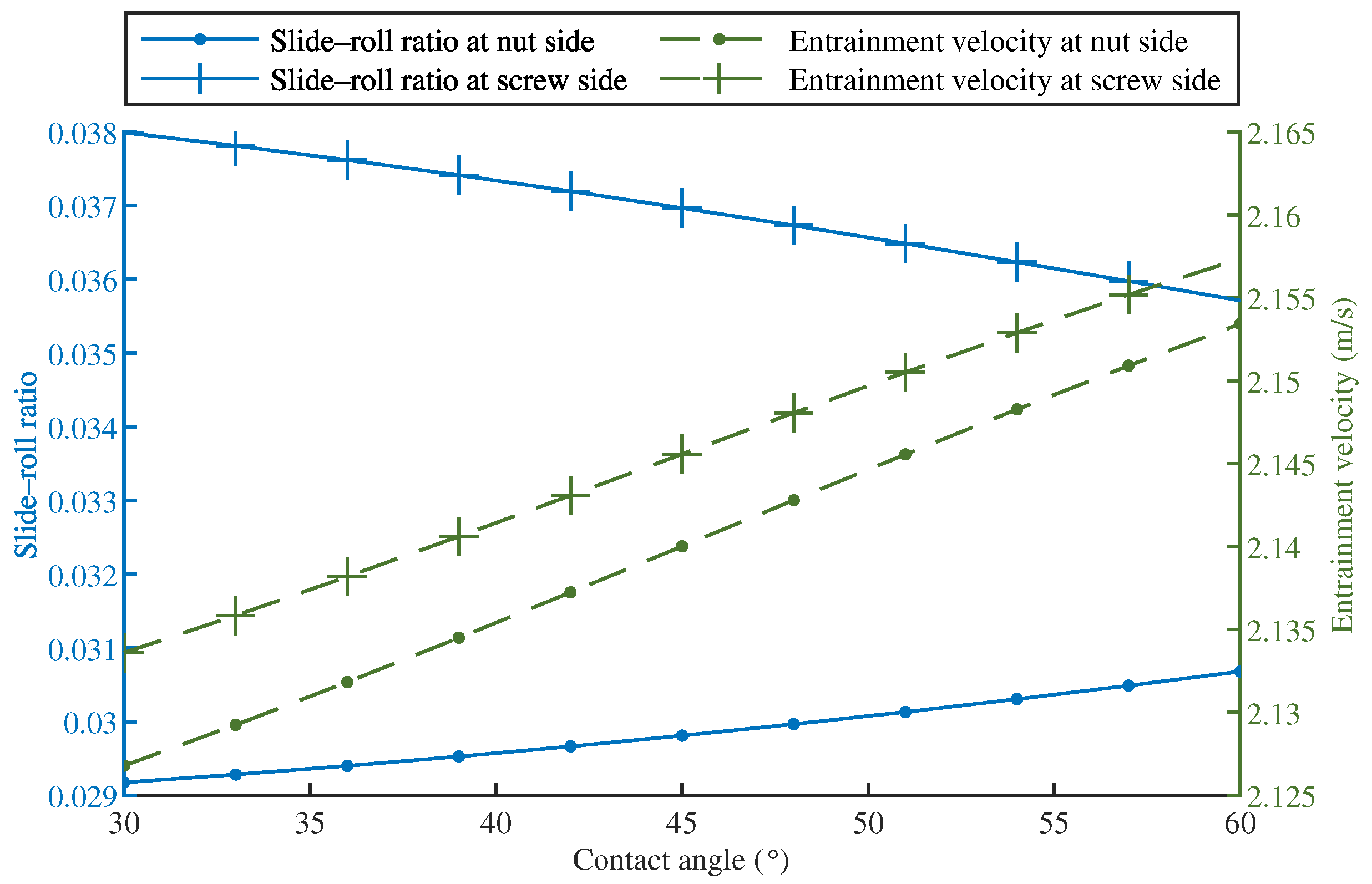
3.4.2. Effect of Contact Angle

The contact angle is a critical parameter in the investigation of the load distribution in BSMs. It varies due to elastic deformations, machining and assembly errors, and other factors. However, as seen in Figure 6, the contact angle has a negligible influence on the slide–roll ratio and entrainment velocity. The slide–roll ratio on the screw side reduces a little as the contact angle rises, while the slide–roll ratio on the nut side increases even less. Increases in contact angle result in a slight increase in entrainment velocity, with the variance being almost equal on both sides. As can be observed, the effect of contact angle variation on the kinematic parameters is essentially negligible.

3.4.3. Effect of Lead Length

The lead length is a critical element impacting the helix angle of the BSM and represents the major differential between ball screws and rolling bearings, resulting in sliding at the ball–raceway contact point. As seen in Figure 7, when the lead grows, the slide–roll ratio increases dramatically on both the screw and nut sides, implying that more sliding occurs at the contact point. The lead increase has a negligible influence on entrainment velocity, which increases slightly on the screw side and lowers somewhat on the nut side. Given the considerable rise in the slide–roll ratio and the absence of a significant change in the entrainment velocity, this implies a significant increase in the sliding velocity.

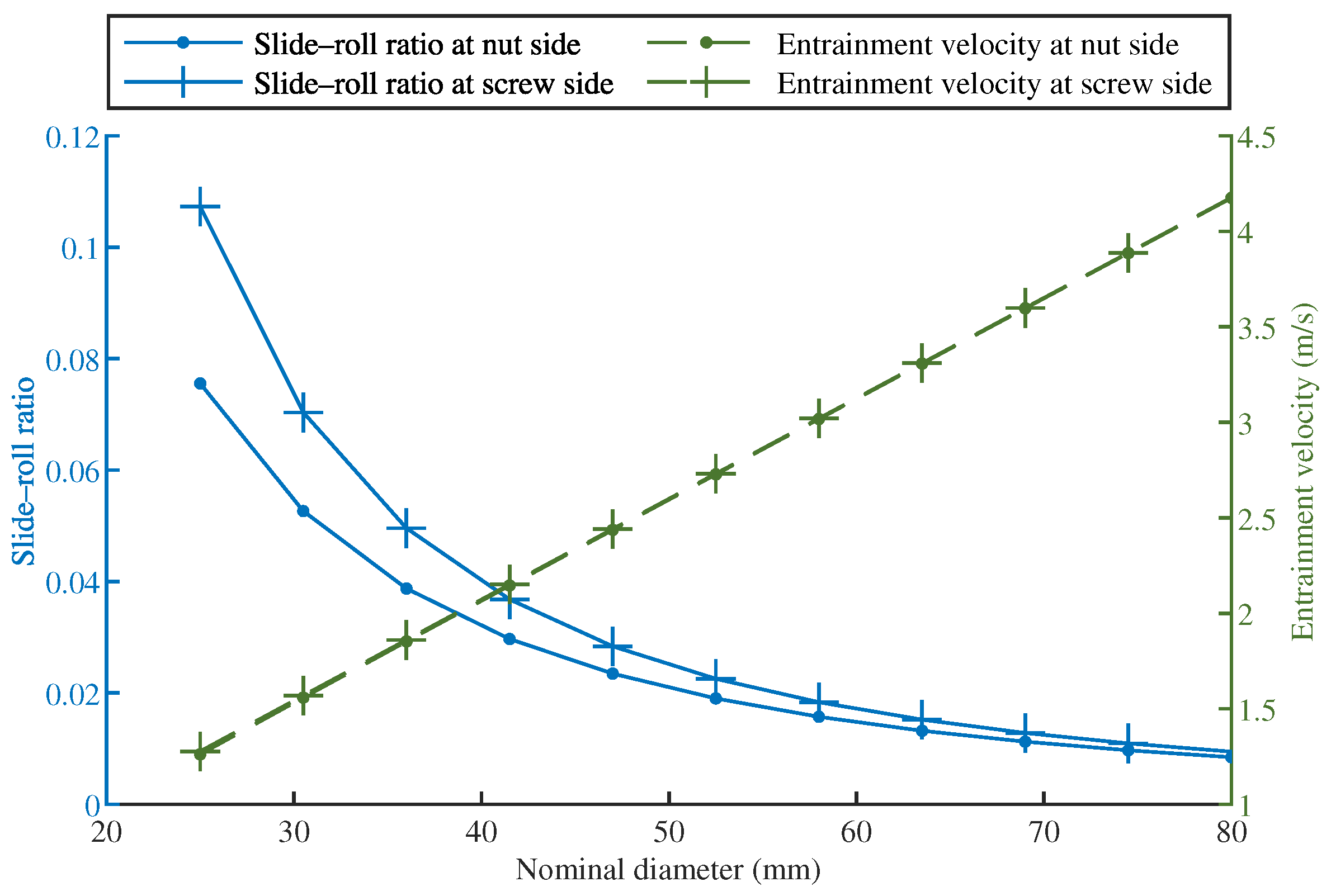
3.4.4. Effect of Nominal Diameter

When the rational speed and lead of the screw are determined, raising the nominal diameter greatly increases the velocity at the contact point and decreases the helix angle. As seen in Figure 8, as the nominal diameter grows, the slide–roll ratio reduces dramatically as the helix lift angle lowers, while the entrainment velocity increases significantly as the linear velocity at the contact point increases.

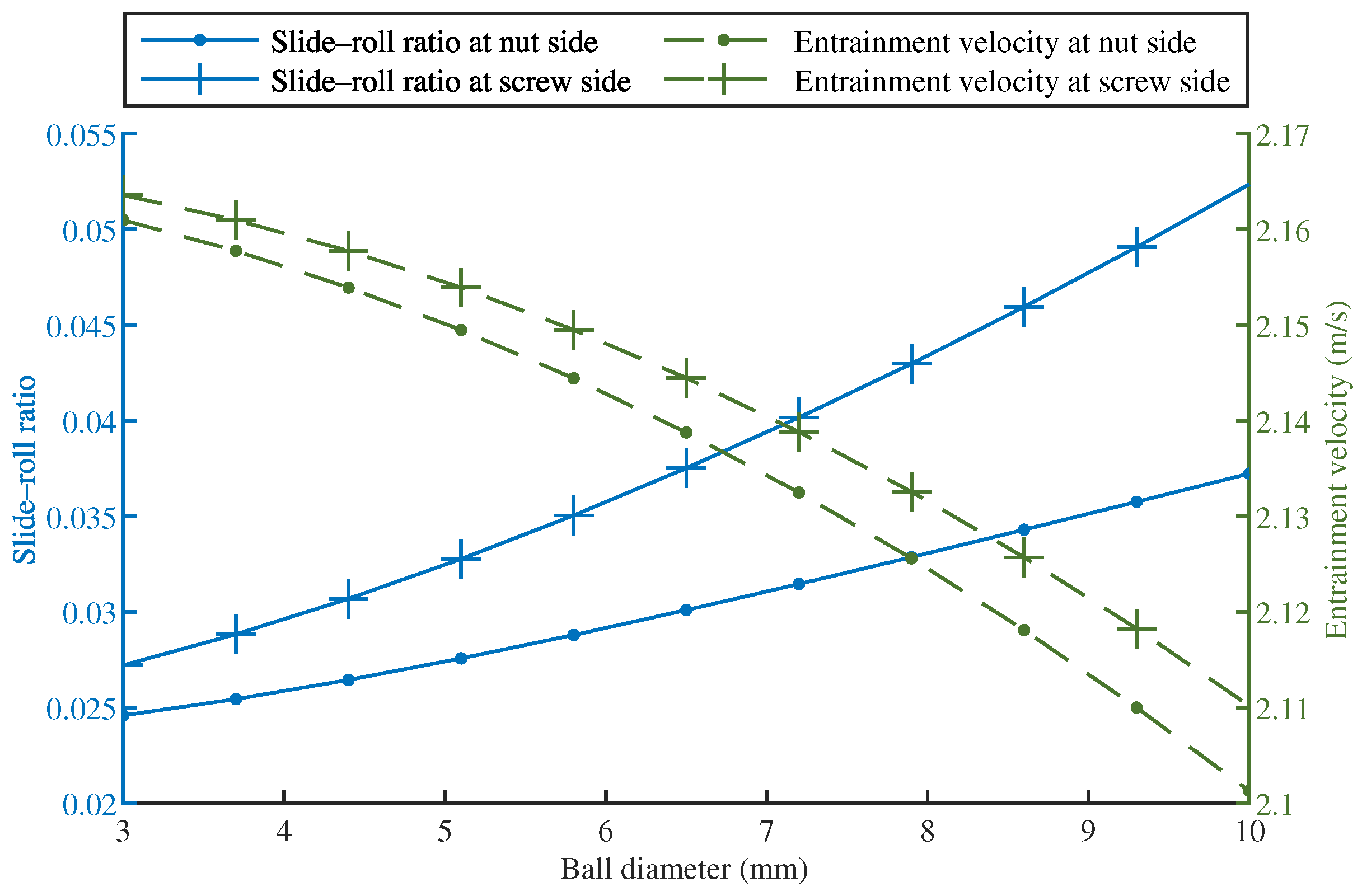
3.4.5. Effect of Ball Diameter

The diameter of the ball has a weak effect on both the slide–roll ratio and entrainment velocity. As seen in Figure 9, the entrainment velocity reduces slightly as the ball diameter increases, owing mostly to a minor decrease in the contact point’s relative velocity. Additionally, increasing the diameter of the ball raises the slide–roll ratio on both sides slightly, but given that decreasing the entrainment velocity also increases the slide–roll ratio, the change in sliding velocity is rather minor.

4. Conclusions

In this study, we proposed a new method for calculating the slide–roll ratio and entrainment velocity of the BSM in terms of relative velocities in the Frenet frame, and the linear velocities of the ball and raceway surfaces at the contact points were derived correspondingly. By applying the current method to ball bearing kinematic and lubrication investigations, this model was validated. We compared our new model’s sliding velocities and slide–roll ratios to those obtained from Wei’s model, demonstrating that the slide–roll ratio based on relative velocities may give a convenient comparison of the sliding behavior on the screw and nut sides. Utilizing this model, we investigated the effect of the BSM’s operating conditions and structural parameters on sliding and lubrication at the contact points and came to the following conclusions:
  • The ball’s centrifugal force was negligible in comparison with the contact load. Centrifugal force had a minor influence on medium-to high-speed operating or small BSMs;
  • The variation of the contact angle had a negligible influence on the centrifugal force and a minor effect on the slide–roll ratio and entrainment velocity. When determining the BSM’s kinematic characteristics, the contact angle at the inner and outer sides can be considered to be equal to the nominal contact angle;
  • The slide–roll ratio and entrainment velocity were close on the inner and outer sides. The slide–roll ratio was usually slightly higher on the screw side than on the nut side, as was the entrainment velocity;
  • The helix angle had the greatest impact on the sliding behavior at the contact points. When either the lead increases or the nominal diameter decreases, the helix angle will be increased, resulting in a significant increase in the slide–roll ratio;
  • The entrainment velocity rose linearly with the screw rotation speed and nominal diameter, while all other construction parameters had a negligible influence. Lubrication can be enhanced and sliding decreased in high-speed BSMs with a long lead by increasing the nominal diameter.

Author Contributions

Conceptualization, W.W. and C.L.; methodology, W.W.; validation, W.W. and L.L.; writing—original draft preparation, W.W.; writing—review and editing, S.C. and C.L.; supervision, S.C. and C.L. All authors have read and agreed to the published version of the manuscript.

Funding

This work was supported by the Shandong Provincial Natural Science Foundation (No. ZR2019MEE034 and No. ZR2019MEE064).

Institutional Review Board Statement

Not applicable.

Informed Consent Statement

Not applicable.

Data Availability Statement

Not applicable.

Acknowledgments

This work was supported by the Key Laboratory of High-efficiency and Clean Mechanical Manufacture at Shandong University, the Ministry of Education, and the National Demonstration Center for Experimental Mechanical Engineering Education at Shandong University.

Conflicts of Interest

The authors declare no conflict of interest.

Nomenclature

CS 0 global coordinate system fixed to the base
CS 1 Frenet coordinate system moved to the ball center
F n centrifugal force of the ball
Llead of the ball screw
mball’s mass
Nnumber of loaded balls
R O A a absolute coordinates of the nut contact point
R O B a absolute coordinates of the screw contact point
R O O a absolute position of the ball center
R O A r vector from the ball’s center to the nut contact point
R O B r vector from the ball’s center to the screw contact point
r b radius of the ball
r m nominal radius of the ball screw
S A slide–roll ratio at the nut contact point
S B slide–roll ratio at the screw contact point
T 1 coordinate transformation matrix from CS 0 to CS 1
T 1 coordinate transformation matrix from CS 0 to CS 1 when θ = 0
U A entrainment velocity at the nut contact point
U B entrainment velocity at the screw contact point
V A e convected velocity at the nut contact point
V B e convected velocity at the screw contact point
V A b a ball’s absolute linear velocities at the contact point with the nut
V A b r ball’s relative linear velocities at the contact point with the nut
V B b a ball’s absolute linear velocities at the contact point with the screw
V B b r ball’s relative linear velocities at the contact point with the screw
V A n a nut’s absolute linear velocities at the contact point
V A n r nut’s relative linear velocities at the contact point
V B s a nut’s absolute linear velocities at the contact point
V B s r screw’s relative linear velocities at the contact point
V S A sliding velocity at the nut contact point
V S B sliding velocity at the screw contact point
X base vector of the global coordinate system CS 0
Y base vector of the Frenet coordinate system CS 1
α nominal contact angle of the ball screw
α i contact angle of ball–screw contact
α o contact angle of ball–nut contact
β ball pitch angle relative to the Frenet frame
β ball yaw angle
γ ratio of r m to r b
ω rotating angular speed of the screw
ω m orbital angular speed of the ball
ω R rotation angular speed of the ball along its own axis
ω R vector of the ball’s rotation angular speed
ω t , ω n , ω b components of the ball’s angular speed along the t-, n-, and b-axis
ϕ rotation angle of the screw
ψ helix angle of the ball screw
θ azimuth angle of the ball
Superscripts  
aabsolute velocity or coordinates
econvected velocity
rrelative velocity or coordinates
Subscripts
Avalues of the contact point at the nut side
Bvalues of the contact point at the screw side
bvalues of the ball (except ω b for pointing along the b-axis)
nvalues of the nut (except F n and ω n for pointing along the n-axis)
svalues of the screw
ζ contact between the ball and the nut/screw raceway
Endings
X vectors expressed in the global coordinate system CS 0
Y vectors expressed in the Frenet coordinate system CS 1

Appendix A

Table A1. List of the BSM parameters.
Parameter (Symbol)ValueUnit
Helix angle ( ψ ) 8.74 deg
Lead (L)20mm
Nominal diameter ( d m ) 41.4 mm
Ball’s diameter ( d b ) 6.35 mm
Ball’s mass (m) 1.05 g
Number of loaded balls (N)52
Nominal contact angle ( α )45deg
Screw’s rotational speed2000rpm

References

  1. Wei, C.C.; Lin, J.F. Kinematic Analysis of the Ball Screw Mechanism Considering Variable Contact Angles and Elastic Deformations. J. Mech. Des. 2003, 125, 717–733. [Google Scholar] [CrossRef]
  2. Oyanguren, A.; Larrañaga, J.; Ulacia, I. Thermo-Mechanical Modelling of Ball Screw Preload Force Variation in Different Working Conditions. Int. J. Adv. Manuf. Technol. 2018, 97, 723–739. [Google Scholar] [CrossRef]
  3. Lin, M.C.; Ravani, B.; Velinsky, S.A. Kinematics of the Ball Screw Mechanism. J. Mech. Des. 1994, 116, 849–855. [Google Scholar] [CrossRef]
  4. Jiang, H.K. Research on Machining Method and Dynamic Performance of Steep-Lead Ball Screw Mechanism. Ph.D. Thesis, Shandong University, Jinan, China, 2007. [Google Scholar]
  5. Mu, S.G. Research on Dynamic Characteristics of High-speed Ball Screw with Nut Driven. Ph.D. Thesis, Shandong University, Jinan, China, 2013. [Google Scholar]
  6. Zhang, L.C.; Zhou, C.G. Experimental Study on the Coefficient of Friction of the Ball Screw. J. Tribol. 2022, 144, 031601. [Google Scholar] [CrossRef]
  7. Wei, C.C.; Lai, R.S. Kinematical Analyses and Transmission Efficiency of a Preloaded Ball Screw Operating at High Rotational Speeds. Mech. Mach. Theory 2011, 46, 880–898. [Google Scholar] [CrossRef]
  8. Hu, J.; Wang, M.; Zan, T. The Kinematics of Ball-Screw Mechanisms via the Slide–Roll Ratio. Mech. Mach. Theory 2014, 79, 158–172. [Google Scholar] [CrossRef]
  9. Mei, X.; Tsutsumi, M.; Tao, T.; Sun, N. Study on the Load Distribution of Ball Screws with Errors. Mech. Mach. Theory 2003, 38, 1257–1269. [Google Scholar] [CrossRef]
  10. Lin, B.; Okwudire, C.E.; Wou, J.S. Low Order Static Load Distribution Model for Ball Screw Mechanisms Including Effects of Lateral Deformation and Geometric Errors. J. Mech. Des. 2018, 140, 022301. [Google Scholar] [CrossRef]
  11. Zhen, N.; An, Q. Analysis of Stress and Fatigue Life of Ball Screw with Considering the Dimension Errors of Balls. Int. J. Mech. Sci. 2018, 137, 68–76. [Google Scholar] [CrossRef]
  12. Zhao, J.; Lin, M.; Song, X.; Guo, Q. Investigation of Load Distribution and Deformations for Ball Screws with the Effects of Turning Torque and Geometric Errors. Mech. Mach. Theory 2019, 141, 95–116. [Google Scholar] [CrossRef]
  13. Liu, C.; Zhao, C.; Meng, X.; Wen, B. Static Load Distribution Analysis of Ball Screws with Nut Position Variation. Mech. Mach. Theory 2020, 151, 103893. [Google Scholar] [CrossRef]
  14. Wei, C.C.; Lin, J.F.; Horng, J.H. Analysis of a Ball Screw with a Preload and Lubrication. Tribol. Int. 2009, 42, 1816–1831. [Google Scholar] [CrossRef]
  15. Zhang, Z.; Zhang, L.; Jiang, H.K. Study on the Lubrication of the Precision Ball Screw Mechanism. J. Mech. Transm. 2015, 39, 22–26. [Google Scholar]
  16. Chaudhary, R.; Pandey, R.; Mazumdar, S. Tribological Studies of Low and High Viscous Oils Lubricated Heavily Loaded Textured Point Contacts under the Reciprocating Motion. Proc. Inst. Mech. Eng. Part J. J. Eng. Tribol. 2020, 234, 229–246. [Google Scholar] [CrossRef]
  17. Maldonado-Cortés, D.; Peña-Parás, L.; Leyva, C.L.; Guerrero, A.; Garza, A.; Quintanilla-Correa, D.; Coronado-Quintanilla, J.; González Aguirre, P. Improvement of Tribological Properties through the Application of Laser Surface Texturing and Nanolubricants in CNC Equipment Elements. Tribol. Ind. 2020, 42, 159–164. [Google Scholar] [CrossRef]
  18. Harris, T.A. An Analytical Method to Predict Skidding in Thrust-Loaded, Angular-Contact Ball Bearings. J. Lubr. Technol. 1971, 93, 17–23. [Google Scholar] [CrossRef]
  19. Harris, T.A. Ball Motion in Thrust-Loaded, Angular Contact Bearings With Coulomb Friction. J. Lubr. Technol. 1971, 93, 32–38. [Google Scholar] [CrossRef]
  20. Harris, T.A.; Kotzalas, M.N. Rolling Bearing Analysis-2 Volume Set; CRC Press: Boca Raton, FL, USA, 2006. [Google Scholar] [CrossRef]
  21. Meng, F.; Zheng, Y.; Liu, Y.; Gong, J.; Wang, B. Multi-Ellipsoid Contact Elastohydrodynamic Lubrication Performance for Deep Groove Ball Bearing. Tribol. Int. 2020, 150, 106367. [Google Scholar] [CrossRef]
  22. Hamrock, B.J.; Dowson, D. Isothermal Elastohydrodynamic Lubrication of Point Contacts: Part III—Fully Flooded Results. J. Lubr. Technol. 1977, 99, 264–275. [Google Scholar] [CrossRef]
  23. Dowson, D.; Taylor, C.M.; Xu, H. Elastohydrodynamic Lubrication of Elliptical Contacts with Spin and Rolling. Proc. Inst. Mech. Eng. Part C Mech. Eng. Sci. 1991, 205, 165–174. [Google Scholar] [CrossRef]
  24. Zhu, D. Elastohydrodynamic Lubrication in Extended Parameter Ranges—Part I: Speed Effect. Tribol. Trans. 2002, 45, 540–548. [Google Scholar] [CrossRef]
Figure 1. Frenet coordinates.
Machines 10 00203 g001
Figure 2. Position of contact points.
Machines 10 00203 g002
Figure 3. Linear velocities of the ball and raceway.
Machines 10 00203 g003
Figure 4. Centrifugal force when rotational speed and contact angle varies.
Machines 10 00203 g004
Figure 5. Slide–roll ratio and entrainment velocity under various rotational speeds.
Machines 10 00203 g005
Figure 6. Slide–roll ratio and entrainment velocity under various contact angles.
Machines 10 00203 g006
Figure 7. Slide–roll ratio and entrainment velocity under various lead lengths.
Machines 10 00203 g007
Figure 8. Slide–roll ratio and entrainment velocity under various nominal diameters.
Machines 10 00203 g008
Figure 9. Slide–roll ratio and entrainment velocity under various ball diameters.
Machines 10 00203 g009
Table 1. Results using ball bearing parameters.
Item (Unit)Present ModelWei’s ModelHarris Method
U A (m/s)15.9947.97115.994
U B (m/s)15.99422.74015.994
S A 0.0002.0000.000
S B 0.0000.7010.000
Table 2. Results using ball screw parameters.
Item (Unit)Present ModelWei’s Model
V A n a (m/s) 0.101 0.000 0.659 Y 0.101 0.000 0.659 Y
V B s a (m/s) 3.820 0.071 0.587 Y 3.820 0.071 0.587 Y
V A b a (m/s) 0.056 0.032 0.691 Y 1.789 0.000 0.659 Y
V B b a (m/s) 3.764 0.032 0.627 Y 1.919 0.000 0.659 Y
V S A (m/s) 0.045 0.032 0.032 Y 1.890 0.000 0.000 Y
V S B (m/s) 0.056 0.040 0.040 Y 1.901 0.072 0.072 Y
U A (m/s)2.1401.071
U B (m/s)2.1462.937
S A 0.0301.766
S B 0.0370.648
Publisher’s Note: MDPI stays neutral with regard to jurisdictional claims in published maps and institutional affiliations.

