
A Review of Key Technologies for High-Speed Motorized Spindles of CNC Machine Tools


Abstract
:1. Introduction
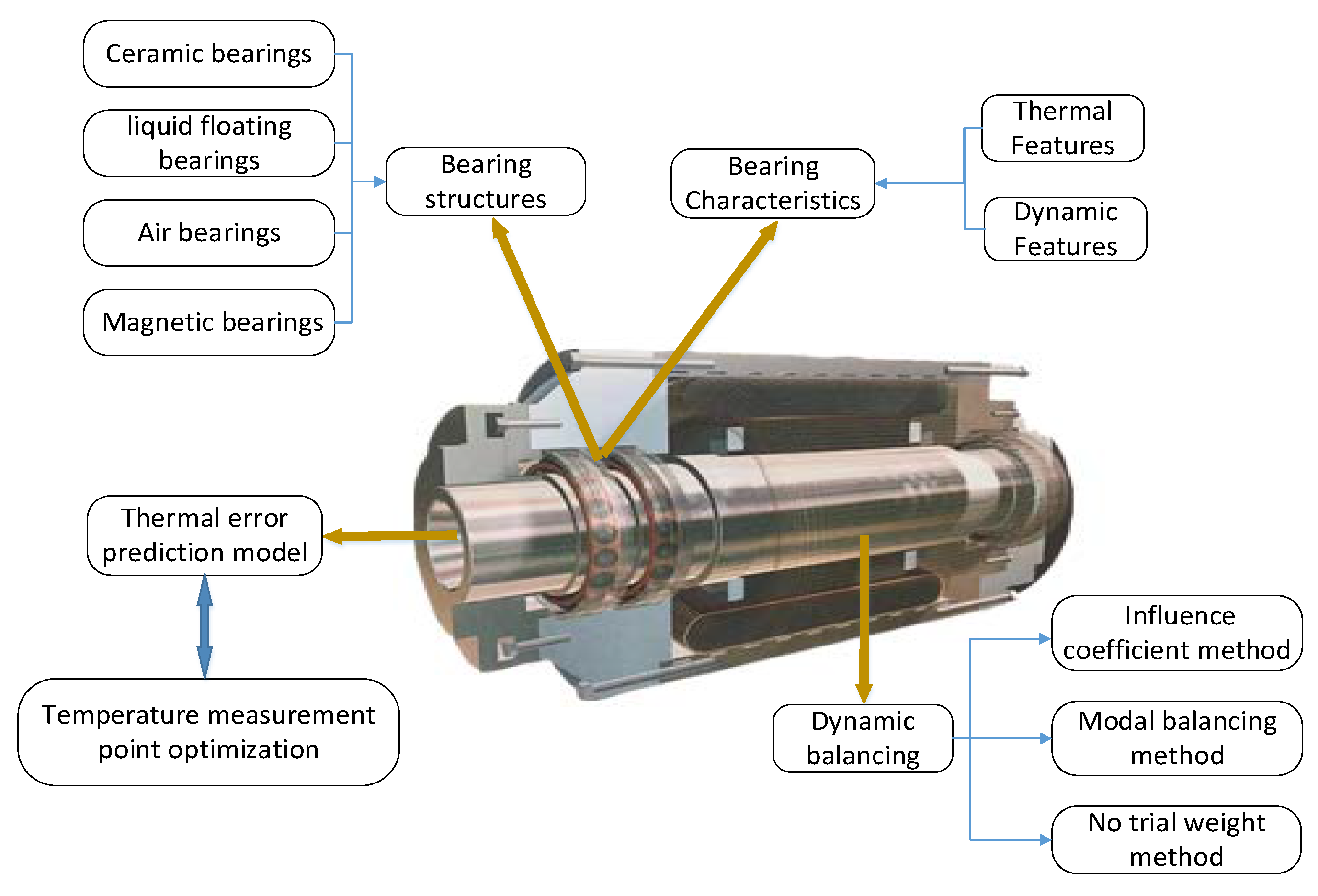
2. Recent Developments in Precision Bearing Technology
2.1. Existing Survey Studies on the Structural Design of Precision Bearings
2.2. Development of Bearing Thermal Performance Research
2.3. Research Progress on the Thermal-Dynamic Coupling Performance of Spindle and Bearing
3. Recent Research on Dynamic Balance Technology
3.1. Influence Coefficient Method
3.2. Modal Balancing Method
3.3. No Trial Weight Method
4. Research Progress of Thermal Error Measurement and Compensation Technology
4.1. Temperature Measurement Point Optimization Technology
4.2. Thermal Error Compensation Modeling Technology
5. Development Trend of High-Speed Motorized Spindle Technology
- (1)
- The development of high precision, high reliability and long life of CNC machine tools is the goal. At present, the precision and reliability of the use of CNC machine tools need to meet higher requirements. As one of the core functional components of CNC machine tools, the high-speed motorized spindle requires higher precision and reliability.
- (2)
- With the improvement of the bearing technology as the goal, the problems of high cost, large structures and difficult to control of magnetic bearings need to be solved. Research and development of high speed and high power shaftless high-speed motorized spindles with magnetic bearings as support must be undertaken.
- (3)
- To improve the running accuracy of the motorized spindle, the research on the generalization of dynamic balancing technology, using a dynamic balancing method that capable to balance the rigid spindle and flexible spindle at the same time, which would help to reduce the impact of vibration on the high-speed motorized spindle, must be accelerated.
- (4)
- To reduce the influence of heat generation and thermal error of the spindle, and improve the accuracy of the spindle, research on the application of computer simulation technology in the design of high-speed motorized spindles must be strengthened, and the development of highly reliable modeling methods to realize the compensation of errors must be achieved.
6. Conclusions
Author Contributions
Funding
Institutional Review Board Statement
Informed Consent Statement
Data Availability Statement
Acknowledgments
Conflicts of Interest
References
- Zhang, L.X.; Li, C.Q.; Li, J.P.; Zhang, K.; Wu, Y.H. The temperature prediction mode of high speed and high precision motorized spindle. J. Mech. Eng. 2017, 53, 129–136. [Google Scholar] [CrossRef]
- Jiang, S.Y.; Zhang, S.W. Progress in the key technologies of high speed motorized spindle supported by water-lubricated bearings. Mach. Des. Manuf. Eng. 2016, 45, 11–17. [Google Scholar]
- Xiong, W.L.; Sun, W.B.; Liu, K.; Xu, M.H.; Pei, T. Active magnetic bearing technology development in high-speed motorized spindles. J. Mech. Eng. 2021, 57, 1–17. [Google Scholar]
- Kang, C.M.; Zhao, C.Y.; Liu, K.; Li, T.J.; Yang, B. Comprehensive compensation method for thermal error of a vertical drilling center. Trans. Can. Soc. Mech. Eng. 2019, 43, 92–101. [Google Scholar] [CrossRef] [Green Version]
- Peng, X.L.; Li, Z. Review of spindle motor technology. Electron. Meas. Technol. 2020, 43, 1–7. [Google Scholar]
- Wu, Y.H.; Xia, Z.X.; Li, S.H.; Chen, S.Z.; Sun, J.; Wang, H.; Tain, J.X.; Wang, Y.H. A Kind of Grease Lubricated Ceramic Bearing with a Piezoelectric Ceramic Inner Ring. China Patent 2019. under review. [Google Scholar]
- Liu, X.L.; Xia, Z.X. A Kind of Dynamic Pressure Gas Radial Ceramic Bearing. China Patent 2018. in press. [Google Scholar]
- Jiang, S.Y.; Xu, W.Z. A Kind of Hydrostatic Water Bearing with Slotted Water Chamber Against Unequal Area Water Chamber. China Patent, 2019, under review.
- Zhang, F.Q. A Kind of Hydrostatic Liquid Floating Bearing. China Patent 2018. in press. [Google Scholar]
- KO, P.H.; Chan, C.M.; Chan, S.T.; Xu, W.Z. Hydrostatic Bearing Monitoring System and Method. U.S. Patent 2017. under review. [Google Scholar]
- Yu, P.L.; Kong, J.Y.; Yang, J.T. An Active Air Float Bearing With Variable Air Film Shape. China Patent 2020. under review. [Google Scholar]
- Yin, Z.Q.; Zhuang, Z.W. A Kind of Air Floating Bearing. China Patent 2021. in press. [Google Scholar]
- Ryu, K.H. Air Bearing and Rotor System. U.S. Patent 2020. in press. [Google Scholar]
- Chen, H.X.; Mao, K.; Han, S.C.; Wu, Z.X.; Zhou, D.S.; Lv, M.D.; Zhang, Z.H.; Gong, J.; Hu, D.Y.; Li, P.; et al. A Hybrid Magnetic Levitation Bearing System. China Patent 2020. in press. [Google Scholar]
- Zhang, F.H.; Hu, Y.S.; Zhang, X.B.; Xu, W.Z. Protective Structure for Magnetic Bearing and Magnetic Bearing Assembly. U.S. Patent 2020. in press. [Google Scholar]
- Chen, Y.; Deng, Y.C.; Tang, W.; Li, L.W.; Miu, X.Y.; Li, Q.; Wang, M. A Coil Type Axial Permanent Magnet Electric Magnetic Floating Bearing. China Patent 2017. in press. [Google Scholar]
- Palmgren, A. Ball and Roller Bearing Engineering, 1st ed.; SKF Industries Inc.: Philadelphia, PA, USA, 1959; pp. 1–264. [Google Scholar]
- Jones, A.B. Ball motion and sliding frictionin ball bearings. J. Fluids Eng. 1959, 81, 1–12. [Google Scholar]
- Harris, T.A.; Mindel, M.H.; Gillespie, J.W. Rolling element bearing dynamics. Wear 1973, 23, 311–337. [Google Scholar] [CrossRef]
- Stein, J.L.; Tu, J.F. A state-space model for monitoring thermally induced preload in anti-friction spindle bearings of high-speed machine tools. J. Dyn. Syst. Meas. Control 1994, 116, 372–386. [Google Scholar] [CrossRef]
- Tu, J.F.; Stein, J.L. Active thermal preload regulation for machine tool spindles with rolling element bearings. J. Manuf. Sci. Eng. 1996, 118, 499–505. [Google Scholar] [CrossRef]
- Bossmanns, B.; Tu, J.F. A thermal model for high speed motorized spindles. Int. J. Mach. Tool 1999, 19, 1345–1366. [Google Scholar] [CrossRef]
- Bossmanns, B.; Tu, J.F. A Power flow model for high speed motorized spindles-heat generation characterization. J. Manuf. Scinece Eng. 2001, 123, 494–505. [Google Scholar] [CrossRef]
- Huang, X.M.; Zhang, B.L.; Xiao, S.H. FEA of thermal properties for high speed motorized spindles. Aeronaut. Manuf. Technol. 2003, 242, 20–23. [Google Scholar]
- Chen, X.A.; Liu, J.F.; He, Y.; Zhang, P.; Shan, W.T. Thermal properties of high speed motorized spindle and their effect. J. Mech. Eng. 2013, 49, 135–142. [Google Scholar] [CrossRef]
- Chen, X.A.; Liu, J.F.; He, Y.; Liu, J.F. Power flow model of high-speed motorized spindles and its thermal characteristics. Trans. Chin. Soc. Agric. Mach. 2013, 44, 250–254. [Google Scholar]
- Zhou, Z.C.; Wang, Y.Q.; Wu, W.W.; Hong, J. Thermally induced preload and stiffness calculation for machine tool spindle bearing. J. Xi’an Jiaotong Univ. 2015, 49, 111–116. [Google Scholar]
- Lu, T.L.; Qiu, M.; Dong, Y.F.; Zhang, Y.T.; Du, H. Research on thermally induced preload of machine tool spindle bearings based on FBG sensor. China Mech. Eng. 2021, 32, 2025–2031. [Google Scholar]
- Meng, Q.Y.; Liu, Y.; Yan, X.X.; Ma, Y.X.; Li, Y.Z. Research on thermal distribution characteristics of motorized spindle system based on fractal theory. J. Mech. Eng. 2021, 57, 63–69. [Google Scholar]
- Kim, S.M.; Lee, S.K. Prediction of thermo-elastic behavior in a spindle-bearing system considering bearing surroundings. Int. J. Mach. Tools Manuf. 2001, 41, 809–839. [Google Scholar] [CrossRef]
- Jiang, X.Q. Study on Heat Characteristics of Spindle Bearing and Influences on Speed and Dynamics. Ph.D. Thesis, Zhejiang University, Hangzhou, China, 2001. [Google Scholar]
- Lin, C.W.; Tu, J.F.; Kamman, J. An integrated thermo-mechanical-dynamic model to characterize motorized machine tool spindles during very high speed rotation. Int. J. Mach. Tools Manuf. 2003, 43, 1035–1050. [Google Scholar] [CrossRef]
- Li, H.Q.; Shen, Y.C.; Kamman, J. Integrated Dynamic thermo-mechanical modeling of high speed spindles, part 2: Solution procedure and validations. J. Manuf. Sci. Eng. 2004, 126, 159–168. [Google Scholar] [CrossRef]
- Holkup, T.; Cao, H.; Kolar, P. Thermo-mechanical model of spindles. ICIRP Ann. 2010, 59, 365–368. [Google Scholar] [CrossRef]
- Song, N. Analysis on Temperature Field and Thermo-Stress Coupling of High Speed Angular Contact Ball Bearing with Spin Heat Generation. Master’s Thesis, Jilin University, Jilin, China, 2001. [Google Scholar]
- Yu, J.; Li, S.S.; Yuan, W.; Chen, X.Y. Dynamic property of spindle bearing considering the Effect of thermal Deformation. J. Aerosp. Power 2013, 30, 97–103. [Google Scholar]
- Liu, J.F.; Zhang, P. Thermo-mechanical behavior analysis of motorized spindle based on a coupled model. Adv. Mech. Eng. 2018, 10, 1687814017747144. [Google Scholar] [CrossRef]
- Zhang, S.H.; Zhang, Z.M. A method to select correcting faces of a double-face dynamic balancing rotor. Adv. Mech. Eng. 2016, 8, 1687814016682892. [Google Scholar] [CrossRef] [Green Version]
- Chen, X.; Liao, M.F.; Zhang, X.M.; Wang, S.J. Field balancing technology for low pressure rotors of high bypass ratio turbofan engines. J. Nanjing Univ. Aeronaut. Astronaut. 2017, 32, 808–819. [Google Scholar]
- Wang, Z.; Tu, W.; Li, J.; Liu, M.H.; Zhu, F.L. High Speed Spindle Online Dynamic Balancing Control Strategy and Experimental Research. Mach. Tool Hydraul. 2019, 47, 61–66. [Google Scholar]
- Zhang, K.; Zhang, C.Y.; Zhang, L.X.; Wu, Y.H. Performance Analysis and experiment of electromagnetic ring balancer during operation. J. Vib. Meas. Diagn. 2018, 38, 34–38. [Google Scholar]
- Zhao, W.Z.; Chen, J.; Zhou, R.M.; Gu, W.F.; Hua, M. Application of double-side dynamic balance method in a two-stage adjustable vane axial flow fan. Power Equip. 2018, 32, 434–436. [Google Scholar]
- Zhang, Z.C.; He, L.D.; Wan, F.T.; Li, Z.W.; Chen, Z. Law of weights transfer based on double-sided dynamic balance. J. Mech. Electr. Eng. 2019, 36, 712–716. [Google Scholar]
- Zhu, Y.T.; Yao, Y.G.; Huang, K.; Li, D.Y.; Zhang, H.T.; Zhai, D.Y. The study of influence coefficient method and its application in the dynamic balancing for high-speed spindle. Mech. Electr. Eng. Technol. 2021, 50, 228–235. [Google Scholar]
- Khulief, Y.A.; Oke, W.; Mohiuddin, M.A. Modally Tuned Influence Coefficients for Low-Speed Balancing of Flexible Rotors. J. Vib. Acoustics. 2014, 136, 024501: 1–024501: 5. [Google Scholar]
- Qu, L.S.; Zhang, X.N.; Wu, S.T.; Qiu, H.; Xu, B.G. Flexible rotor holographic field dynamic balancing technology and application. J. Manuf. Sci. Eng. 2005, 12, 75. [Google Scholar]
- Liu, S.; Qu, L.S. A study of methods for an on-site shafting dynamic balance based on a holographic spectrum technology. J. Eng. Therm. Energy Power 2009, 24, 24–30. [Google Scholar]
- Chen, X.; Liao, M.F.; Liu, Z.C.; Li, Y. Model balancing method for flexible rotors with elastic supports. J. Nanjing Univ. Aeronaut. Astronaut. 2016, 48, 402–409. [Google Scholar]
- Liu, C.; Liu, G. Field dynamic balancing for rigid rotor-AMB System in a magnetically suspended flywheel. IEEE/ASME Trans. Mechatron. 2016, 21, 1140–1150. [Google Scholar] [CrossRef]
- Luo, Z.; Wei, Y.H.; Hou, X.J.; Wang, F. Dynamical Balance and Verification of a Rotor System Based on Sensitivity Analysis. J. Vib. Test. Syst. Dyn. 2018, 3, 271–280. [Google Scholar] [CrossRef]
- Sun, H. Analysis of Imbalance Vibration Behavior of High Speed Spindle and Research of its Suppression Method. Master’s Thesis, Xidian University, Xi’an, China, 2015. [Google Scholar]
- Bin, G.F.; He, L.D.; Gao, J.J.; Li, L.B. High-speed dynamic balancing method for low pressure rotor of a large steam turbine based on modal shape analysis. J. Vib. Shock 2013, 32, 87–92. [Google Scholar]
- Jia, S.X.; Zheng, L.X.; Deng, W.Q.; Mei, Q. Development of modal balancing system without trail weights for high speed flexible rotors. J. Vib. Shock 2018, 38, 1108–1113. [Google Scholar]
- Zhang, Y.; Sun, H.; Hu, Z.B. Behavior analysis and suppression strategy for unbalanced vibration in high-speed spindle. J. Xi’an Jiaotong Univ. 2019, 53, 24–29. [Google Scholar]
- Xu, Y.; Yi, J.; Deng, H.; Zhou, F.; Han, Z.J.; Zeng, M.H. Dynamic balance method without trial weights for a folding shaft based on the reverse structural designing. J. Vib. Shock 2019, 38, 263–270. [Google Scholar]
- Zhang, R.X.; Wen, G.R.; Zhang, Z.F.; Xu, B. Multi-unbalances identification of rotor system integrated with GA-PSO method. J. Vib. Meas. Diagn. 2019, 39, 801–809. [Google Scholar] [CrossRef]
- Zhang, Y.; Li, M.; Yao, H.Z.; Gou, Y.J.; Wang, X.Y. A modal-based balancing method for a high-speed rotor without trial weights. Mech. Sci. 2021, 12, 85–96. [Google Scholar] [CrossRef]
- Li, G.L.; Tang, X.D.; Li, Z.Y.; Xu, K.; Li, C.Z. The temperature-sensitive point screening for spindle thermal error modeling based on IBGOA-feature selection. Precis. Eng. 2022, 73, 140–152. [Google Scholar] [CrossRef]
- Yan, Z.Y.; Yang, J.G.; Zhang, Z.F.; Xu, B. Application of synthetic grey correlation theory on thermal point optimization for machine tool thermal error compensation. Int. J. Adv. Manuf. Technol. 2009, 43, 1124–1132. [Google Scholar] [CrossRef]
- Shen, Z.H.; Yang, S.Q. Research on optimization method of temperature measuring point arrangement based on fuzzy clustering and correlative degree analysis. Mod. Manuf. Eng. 2018, 458, 112–118. [Google Scholar]
- Zhou, C.Y.; Zhuang, L.Y.; Yuan, J.; Gao, C.Y. Optimization and experiment of temperature measuring points for machine tool spindle based on K-means algorithm. Mach. Des. Manuf. 2018, 5, 41–43. [Google Scholar]
- Zhang, L.; Chen, G.H.; Zhao, D.Z.; Xiang, H.; Liu, M.D. Optimization method of machine tool spindle temperature measuring point based on fuzzy clustering and grey theory. Mach. Tool Hydraul. 2020, 48, 85–90. [Google Scholar]
- Xue, B.Y. Analysis for thermal error of the spindle by numerical modeling. Machinery 2009, 36, 31–33. [Google Scholar]
- Miao, Y.M.; Liu, Y.; Yang, S.X.; Chen, W.G. Applications of split unbiased estimation algorithm in thermal error modeling of CNC machining center. China Mech. Eng. 2016, 27, 2131–2136. [Google Scholar]
- Zhou, H.M.; Wang, Z. Cooling prediction of motorized spindle based on multivariate linear regression. J. Phys. Conf. Ser. 2021, 1820, 012196. [Google Scholar] [CrossRef]
- Jiang, H.; Yang, J.G. Application of an optimized grey system model on 5-Axis CNC machine tool thermal error modeling. In Proceedings of the IEEE.2010 International Conference on E-Product E-Service and E-Entertainment, Henan, China, 7–9 November 2010. [Google Scholar] [CrossRef]
- Zhang, Y.; Yang, J.; Jiang, H. Machine tool thermal error modeling and prediction by grey neural network. J. Compos. Mater. 2012, 59, 1065–1072. [Google Scholar] [CrossRef]
- Wang, J.C.; Lin, S.Q.; Shen, Y.X.; Xie, C.X.; Deng, X.L. Measurement point optimization and modeling techniques of spindle thermal error for CNC machine tool. Aeronaut. Manuf. Technol. 2019, 62, 41–46. [Google Scholar]
- Ma, C.; Zhao, L.; Mei, X.S. Thermal error modeling of machine tool spindle based on particle swarm optimization and neural network. J. Shanghai Jiaotong Univ. 2016, 50, 686–695. [Google Scholar]
- Xie, J.; Huang, S.D.; Fang, C.G. Thermal error analysis based on MEA optimized BP neural network for motorized spindle. Modul. Mach. Tool Autom. Manuf. Tech. 2017, 6, 1–4. [Google Scholar]
- Wu, Z.W.; Wang, Y.P.; Zhou, H.B. Research on thermal error compensation of machine tool spindle based on simulated annealing coupled particle swarm optimization and BP neural network. Mach. Tool Hydraul. 2019, 49, 92–95. [Google Scholar]
- Sun, A.; Liu, M.L.; Xie, X.L.; Yu, H.C. Thermal error modeling of lathe spindle based on wavelet neural network optimized by bat algorithm. Mach. Tool Hydraul. 2021, 49, 118–123. [Google Scholar]
- LV, C.; Liu, Z.Y.; Liu, Z.J.; Yu, Z.M. Application of generalized radial basis function neural network to thermal error modeling. Opt. Precis. Eng. 2015, 23, 1705–1713. [Google Scholar]
- Zhang, J.; Li, Y.; Wang, S.T.; Gou, W.D. High-speed motorized spindle thermal error modeling based on genetic RBF neural network. J. Huazhong Univ. Sci. Technol. (Nat. Sci. Ed.) 2018, 46, 73–77. [Google Scholar]


| Reference | Brief Summary | Type of Bearing | Objective |
|---|---|---|---|
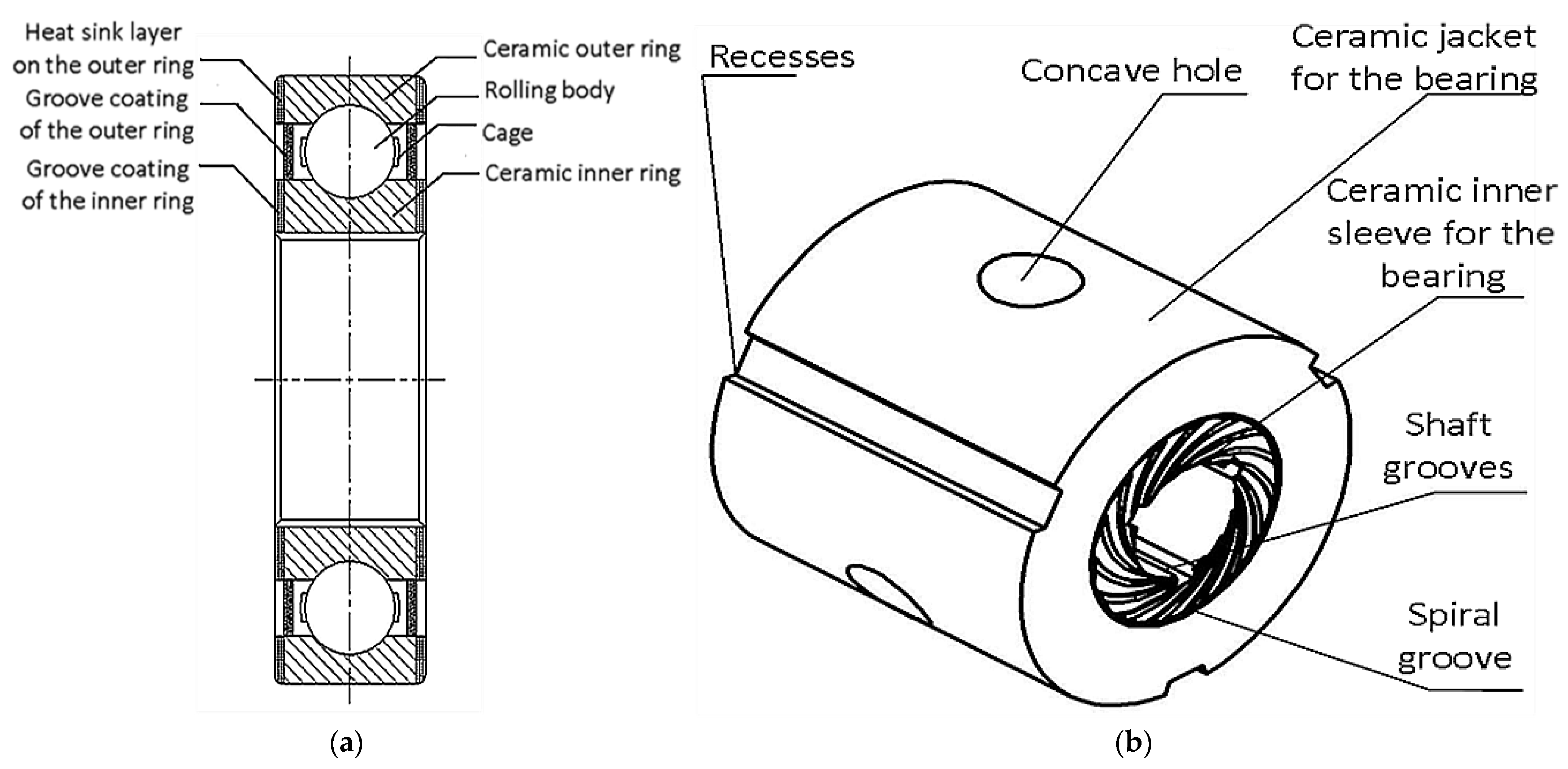
| Wu et al. [6] | Grease lubricated ceramic bearing with piezoelectric ceramic inner ring | Ceramic bearing | Avoid the noise caused by fracture or slipping of the inner ring of the bearing |
| Liu et al. [7] | New Dynamic Pressure Gas Radial Ceramic Bearing | Ceramic bearing | High stability of high-speed rotating spindle |
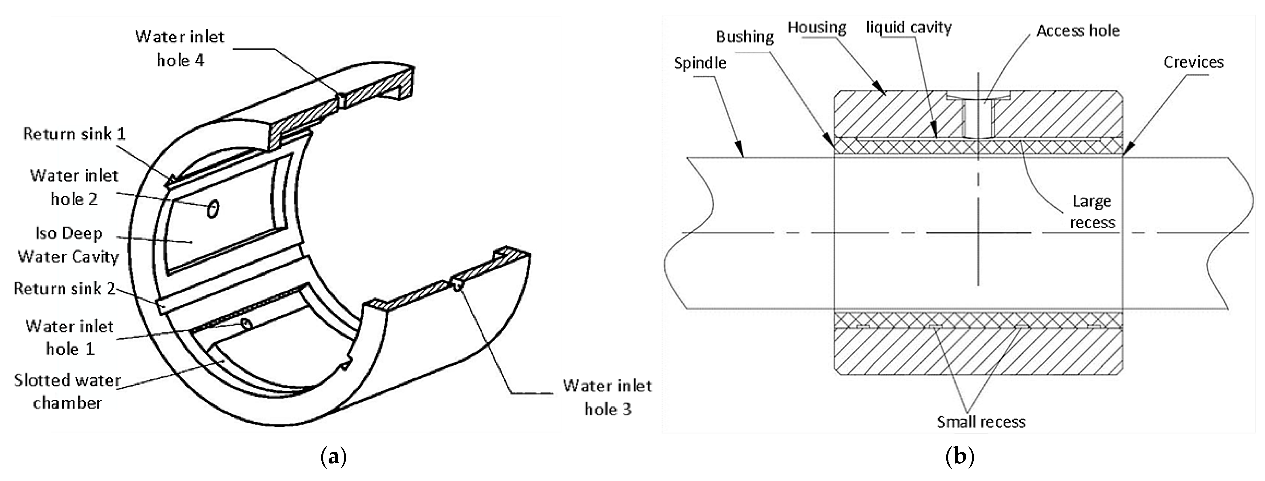
| Jiang et al. [8] | Liquid hydrostatic bearing of the slotted water cavity type with varying opposing areas | Liquid floating bearing | Provide large hydrostatic load capacity and overcome the defect of low rotation accuracy of spindle at high speed |
| Zhang et al. [9] | Hydrostatic floating bearing of through-hole type | Liquid floating bearing | Simple structure, easy to achieve the purpose of spindle suspension |
| Ko et al. [10] | Hydrostatic bearing monitoring system and monitoring method | Liquid floating bearing | Real-time monitoring of hydrostatic bearing performance and fault warning |
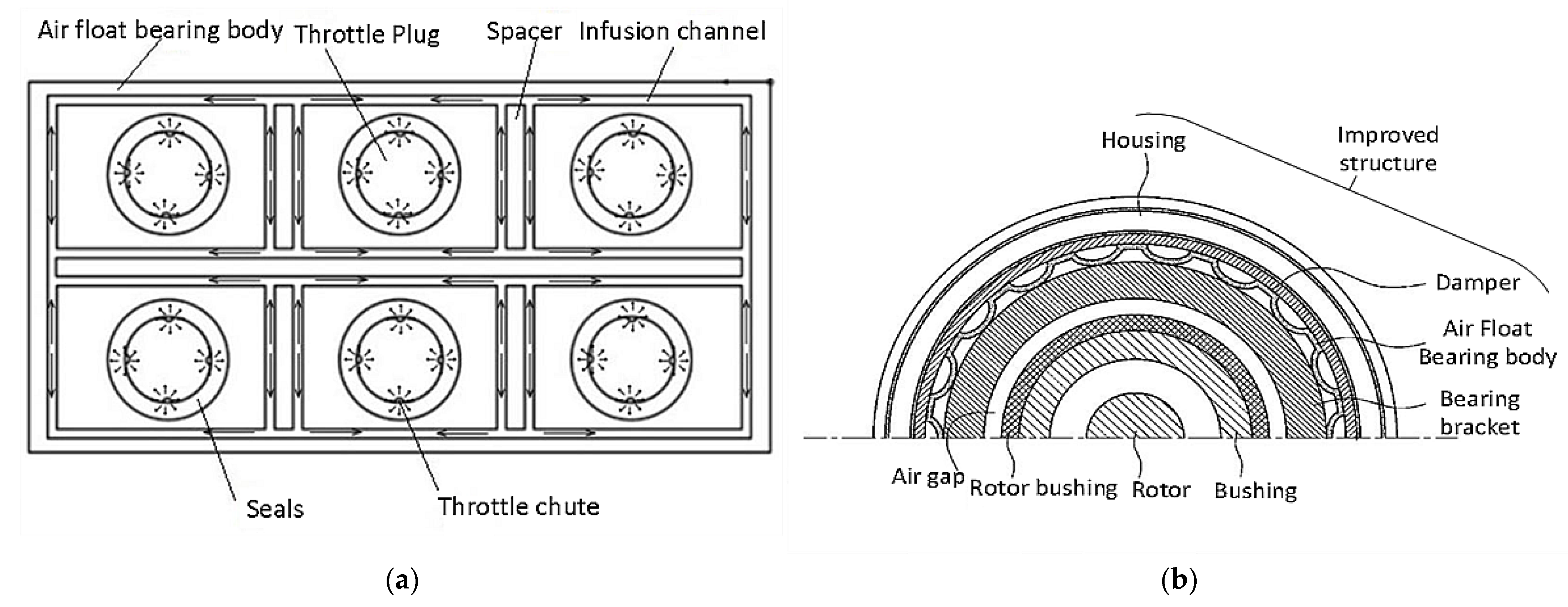
| Yu et al. [11] | Ultra-precise air bearing with active compound throttling type | Air bearing | Suppress micro-amplitude vibration of air-bearing, improve dynamic stiffness |
| Yin et al. [12] | Air bearing with replaceable throttle plug | Air bearing | Effectively avoid the phenomenon of “air hammer” in bearing |
| Keun et al. [13] | Improved structure of the new air bearing | Air bearing | Avoid thermal deformation of bearing or spindle caused by dynamic instability of the rotor and high speeds |
| Chen et al. [14] | Hybrid magnetic bearing structure | Magnetic bearing | Effective simplification of magnetic floating bearing structure, saving cost |
| Zhang et al. [15] | Protective structures for magnetic bearings and magnetic assemblies | Magnetic bearing | Solve the problem of spindle and bearing wear due to easy failure of the magnetic bearing protection structure |
| Chen et al. [16] | Coil type axial permanent magnet electric magnetic bearing | Magnetic bearing | Realize axial bidirectional self- stabilization, less resistance and lower energy consumption |
| Reference | Brief Summary | Year | Objective |
|---|---|---|---|
| Palmgren et al. [17] | The bearing heat source model is proposed for the first time | 1959 | The subsequent research on thermal characteristics of spindle has laid a foundation |
| Jones et al. [18] | The calculation method of friction force and friction moment in the contact area of the raceway is proposed | 1959 | Mainly used to solve for bearing spin-sliding friction heat generation |
| Harris et al. [19] | A temperature network distribution method for bearing system is proposed | 1973 | Laying the groundwork for a heat transfer model of the bearing |
| Stein et al. [20] | Internal heat transfer network of the bearing is established | 1994 | The effect of transient preload force changes caused by uneven thermal expansion of the bearing is investigated |
| Tu et al. [21] | Thermally induced preload force model for motorized spindles is proposed | 1996 | Analysis of the changes in bearing preload force caused by thermal expansion |
| Bossmanns et al. [22] | Analysis model of motorized spindle heat source based on finite element difference method is proposed | 1999 | Effective analysis and calculation of the heat source and heat transfer mechanism of the spindle system |
| Bossmanns et al. [23] | A qualitative power flow model is proposed | 2001 | To provide a theoretical basis for the subsequent study of the power balance of heat generation and heat dissipation in a motorized spindle |
| Huang et al. [24] | A finite element model of the temperature field of high-speed motorized spindle was established | 2003 | The loss heat generation of motor and friction heat generation of bearing is studied |
| Chen et al. [25] | A thermal-mechanical coupling model of a single-row angular contact ball bearing is established | 2013 | The factors influencing the thermal response and preload mode of the system are investigated |
| Chen et al. [26] | The motorized spindle power flow model was established based on the law of energy conservation | 2013 | Refined analysis of the motor loss model for more accurate heat generation calculations in the thermal state model |
| Zhou et al. [27] | The thermal-mechanical coupling analysis model of high-speed motorized spindle is established | 2015 | The effects of spindle speed, initial preload and ambient temperature on bearing preload are studied |
| Lu et al. [28] | A thermally induced preload testing system for bearings is established | 2021 | A new measurement technique for online monitoring of bearing preload is proposed |
| Meng et al. [29] | The thermal resistance network model based on fractal theory is proposed | 2021 | Reliability of fractal theory applied to thermal resistance network models for predicting temperature rise is demonstrated |
| Reference | Brief Summary | Year | Objective |
|---|---|---|---|
| Kim et al. [30] | An integrated thermal-mechanical prediction model was developed | 2001 | Study on the frictional torque and heat generation of bearings to change the spindle system stiffness angle |
| Jiang et al. [31] | The calculation model of thermal deformation and inherent frequency of the spindle is proposed | 2001 | The problem of nonlinear characteristics of bearing load and bearing deformation and the effect of frictional heat is solved |
| Lin et al. [32] | The dynamic-thermal functional model of the integrated high-speed motorized spindle is established | 2003 | The effect of thermally induced preload on bearing stiffness and overall spindle dynamics is quantitatively discussed |
| Li et al. [33] | The dynamics model of the spindle- bearing “thermal-mechanical coupling” system is established. | 2004 | Motorized spindles with complex physical characteristics or geometries are solved |
| Holkup et al. [34] | The thermal-mechanical coupling model of the spindle-bearing system is established based on the finite element method | 1996 | The spindle-bearing system model can accurately predict the temperature distribution and thermal displacement of the system is verified |
| Song et al. [35] | The spin-generated heat model of the bearing is established | 1999 | Analysis of the causes of bearing failure provides guidance for predicting dangerous bearing failures |
| Yu et al. [36] | A coupled model of dynamic-thermal characteristics of the bearing is established based on the thermal network method | 2001 | Study on the effect of thermal deformation on bearing contact parameters under different operating conditions |
| Liu et al. [37] | The thermal-mechanical coupling dynamics model of a high-speed motorized spindle is established | 2003 | To provide a theoretical basis for subsequent research on thermal compensation of high-speed motorized spindles |
| Reference | Brief Summary | Method | Objective |
|---|---|---|---|
| Zhang et al. [38] | Influence coefficient method for maximum total phase difference | Influence coefficient method | Provide the theoretical basis for the two-sided impact factor method |
| Chen et al. [39] | Online dynamic balancing method for low pressure rotors with least squares influence factor | The vibration amplitude of the rotor is reduced | |
| Wang et al. [40] | Single plane influence coefficient method | The problems of misalignment and long equilibrium time during mass movement are solved | |
| Zhang et al. [41] | Single plane influence coefficient method | The choice of counterweight position is proposed | |
| Zhao et al. [42] | Dual-plane influence coefficient method | Verified that the dual-plane influence coefficient method is more effective in optimizing vibration measurement points | |
| Zhang et al. [43] | Dual-plane influence coefficient method | The effect law of counterweight size with counterweight plane shift was found | |
| Zhu et al. [44] | Single and dual-plane influence coefficient method | The multifaceted influence coefficient method applied to flexible rotors is derived | |
| Khulief et al. [45] | Combined influence coefficient method and modal equilibrium method | Low-speed balancing problem of high-speed rotors is solved | |
| Qu et al. [46] | Holographic spectrum theory | Modal equilibrium method | A new technique of holographic spectrum is introduced on the basis of the modal balance method |
| Liu et al. [47] | On-site holographic dynamic balancing method | Multiple sensor information is fused with flexible rotor balancing technology to improve rotor balancing accuracy | |
| Chen et al. [48] | Modal dynamic balance method for flexible rotors | The reliability of the flexible rotor modal dynamic balancing method was verified | |
| Liu et al. [49] | Dual-plane spindle balancing method based on the modalities of the spindle | The validity of dual-plane dynamic balancing method is proved | |
| Zhong et al. [50] | Modal equilibrium theory | Avoid the blindness of choosing the frontal and balance speed | |
| Sun et al. [51] | The dynamic balancing method without trial weight based on multi-factor coupled finite element dynamics model | No trial weight method | The unbalanced vibration of each stage of the spindle is suppressed |
| Bin et al. [52] | The least squares method solves the system of equilibrium vector equations to obtain the equilibrium counterweight | Complete dynamic balancing of the flexible spindle without trial weight is achieved | |
| Jia et al. [53] | The dynamic balancing method without trial weight for high-speed flexible rotors | The problem of low balancing efficiency due to multiple test weights required for traditional dynamic balancing is solved | |
| Zhang et al. [54] | Based on a multivariant finite element analysis model, the dynamic balancing method without trial weight is performed | The model can accurately describe the dynamic characteristics of the spindle | |
| Xu et al. [55] | Dynamic balancing method without trial weight | The method is proven to reduce the unbalance of rotating shafts | |
| Zhang et al. [56] | Genetic algorithm and particle swarm optimization are combined to identify multi-point unbalance of rotor | The reliability of neural network algorithms for online prediction of rotor’s unevenness is proposed | |
| Zhang et al. [57] | the dynamic balancing method without trial for modalities | Suppression of vibration caused by rotor unbalance |
| Reference | Method | Type |
|---|---|---|
| Sun et al. [58] | Improved Binary Locust Optimization Algorithm and Stepwise Regression Method | Stepwise Regression Method |
| Yan et al. [59] | Gray System Theory | Gray System Theory Method |
| Shen et al. [60] | Fuzzy C-means clustering and correlation analysis method | Fuzzy clustering method |
| Zhou et al. [61] | K-means clustering algorithm | Fuzzy clustering method |
| Zhang et al. [62] | Fuzzy clustering combined with gray theory | Fuzzy clustering method |
| Reference | Brief Summary | Method | Effect of Prediction Accuracy |
|---|---|---|---|
| Xue et al. [63] | Partial least squares regression method | Multiple linear regression method | Average |
| Miao et al. [64] | Unbiased estimation splitting method | Multiple linear regression method | Good |
| Zhou et al. [65] | Classical multiple linear regression method | Multiple linear regression method | Fair |
| Jiang et al. [66] | Standard grey system model | Multiple linear regression method | Average |
| Zhang et al. [67] | Serial Grey neural network and parallel grey neural network | Grey theory | Good |
| Wang et al. [68] | Comparison of grey prediction model and BP neural network prediction model | - | - |
| Ma et al. [69] | Particle swarm optimization optimized BP model | Neural network | Good |
| Xie et al. [70] | Thinking evolutionary algorithm optimized BP model | Neural network | Good |
| Wu et al. [71] | Simulated annealing algorithm coupled with particle swarm algorithm to optimize BP model | Neural network | Good |
| Sun et al. [72] | Bat algorithm optimized BP model | Neural network | Excellent |
| Lv et al. [73] | Generalized radial basis function neural network prediction model | Neural network | Good |
| Zhang et al. [74] | Optimization of radial basis function neural network model by genetic algorithm | Neural network | Excellent |
Publisher’s Note: MDPI stays neutral with regard to jurisdictional claims in published maps and institutional affiliations. |
© 2022 by the authors. Licensee MDPI, Basel, Switzerland. This article is an open access article distributed under the terms and conditions of the Creative Commons Attribution (CC BY) license (https://creativecommons.org/licenses/by/4.0/).
Share and Cite
Dai, Y.; Tao, X.; Li, Z.; Zhan, S.; Li, Y.; Gao, Y. A Review of Key Technologies for High-Speed Motorized Spindles of CNC Machine Tools. Machines 2022, 10, 145. https://doi.org/10.3390/machines10020145
Dai Y, Tao X, Li Z, Zhan S, Li Y, Gao Y. A Review of Key Technologies for High-Speed Motorized Spindles of CNC Machine Tools. Machines. 2022; 10(2):145. https://doi.org/10.3390/machines10020145
Chicago/Turabian StyleDai, Ye, Xueshi Tao, Zhaolong Li, Shiqiang Zhan, Yang Li, and Yanhua Gao. 2022. "A Review of Key Technologies for High-Speed Motorized Spindles of CNC Machine Tools" Machines 10, no. 2: 145. https://doi.org/10.3390/machines10020145
APA StyleDai, Y., Tao, X., Li, Z., Zhan, S., Li, Y., & Gao, Y. (2022). A Review of Key Technologies for High-Speed Motorized Spindles of CNC Machine Tools. Machines, 10(2), 145. https://doi.org/10.3390/machines10020145