Abstract
In order to achieve the normal walking of hemiplegic patients, this paper proposes a single-legged exoskeleton robot according to the bionics principle, and presents an adaptive adjustment strategy for walking characteristics. The least square regression analysis is used to fit the angle data of healthy leg joints by cubic polynomials, and then the parametric design of the fitted curve is carried out to obtain the influence of the user’s stride frequency and stride length on the joint angle, so that the gait of the exoskeleton can be adjusted in real time according to the stride length and stride frequency of the healthy leg to realize normal walking. In order to verify the effectiveness of the adaptive adjustment strategy proposed in this paper, the angle of leg joints under normal gait is collected in advance. In addition, an adult male is chosen as the subject to walk on the horizontal ground wearing the single-legged exoskeleton as the experiment. The experimental results show that the designed exoskeleton is reasonable, and the adaptive adjustment strategy proposed in this paper can make the exoskeleton adapt well and follow the gait of healthy legs to achieve a more natural walking state.
1. Introduction
The development of medical rehabilitation exoskeleton robot makes it possible for amputees or hemiplegics to walk normally [1,2]. In order to help patients with lower limb dyskinesia walk normally, various exoskeleton robots and their control algorithms have been developed by researchers. In order to realize better cooperation between humans and robots, the reliable exoskeleton robot platform and effective control algorithm are particularly important [3]. As mentioned in [4,5,6,7], exoskeleton robots can provide people with movement support, some of which can also enhance the strength, speed, and endurance of operators. In addition, the emergence of lower limbs exoskeleton robots increases the possibility of hemiplegia patients’ recovery [8,9]. In actual, research on lower limb exoskeletons have been carried out for decades. The exoskeleton can also be called a power assist equipment. Kawamoto et al. [10] have pointed out that the power assist is performed according to the operators’ intention by using the electromyogram signal as the primary command signal. It stores walking patterns generated by the first time when the person tries on the suit. There is a famous powered exoskeleton suit called HAL (Hybrid Assistive Limb), which is developed by Japan’s Tsukuba University and the robotics company Cyberdyne. The exoskeletal frame of the HAL3 system consists of a four-link, three joint mechanism with the links corresponding to the hip, the thigh, the shank, the foot, and the joints corresponding to the hip, the knee, and the ankle joints of the human body [11,12,13]. In [14], a bipedal driven balance assist system is proposed, which enables the operator to improve the balance force by manipulating the robot, thus reducing the problem of autonomous walking. In [15], an exoskeleton embedded sensing system is designed to obtain the motion data of the user by mapping the motion information of the exoskeleton to the human body. Many existing studies on dynamic exoskeleton related to spinal cord injury are reviewed in [16], which points out that the exoskeleton technology currently used on the ground is relatively novel, and the long-term use of exoskeleton for gait training is very effective. There are various driving methods of the exoskeleton. Yang et al. have proposed a novel lower limb exoskeleton which is driven by linear single-rod electrohydraulic actuators. It combines the mechanical structure of the exoskeleton with an embedded electronic system to perform periodic output tracking [17]. Tang et al. have designed a new gait rehabilitation robot using a cable-driven parallel mechanism in pairwise cable arrangement, which enables alleviating discomfort of patients and relieving potential dangers from rigid robots compared to conventional rehabilitation rigid-link robots [18]. In addition, this exoskeleton can also detect falling and make the necessary movements. The balance of hip joints plays a vital role in exoskeleton assisted walking. Therefore, a new balanced auxiliary control strategy for hip joint exoskeleton robot is proposed. The walking balance is implemented through a hierarchical balance assistive controller based on the virtual stiffness model of an extrapolated center of mass to improve the stability margin [19,20].
In recent years, exoskeletons have been increasingly used in the medical field. Many existing bionics companies have designed the medical exoskeleton and proposed that the medical exoskeleton can provide paraplegic patients with the ability to walk again, but it can hardly achieve a balance between speed and stability at the same time [21]. Esquenazi et al. indicate that, according to the user’s walking ability, clinicians can change the energy provided to each leg through intelligent assistant software [22], so that it can obtain the most suitable auxiliary force. Wheelchairs have long been the preferred tool for paraplegics, but they are not as flexible as walking with two legs. In light of this, suitX of California designs a two-legged medical exoskeleton that weighed just 27 pounds to free paraplegics from the shackles of traditional wheelchairs in 2016. It is relatively flexible and can adjust according to the size of body. For the realization of exoskeleton assisted patient walking, the most critical is the estimation of human walking intention. An online learning and prediction algorithm of joint trajectory and joint torque is proposed, which can predict smooth human joint trajectory and joint torque curve in real time, and can compensate the phase delay caused by sensor signal filtering [23].
The above exoskeleton products are mostly designed with two legs. However, if a hemiplegic patient has a healthy leg and a hemiplegic leg, a single-leg exoskeleton can be used to make full use of the information about the patient’s healthy leg and increase the patient’s active participation in walking. It is pointed out in literature [24] that, in this case, the use of a single-leg exoskeleton can reduce the weight burden of hemiplegia patients, and it is effective and convenient for the movement recovery of hemiplegia patients. In consideration of these imperfections, Hassanet et al. [25] introduced a wearable sense system for the single-legged exoskeleton to generate a stable gait, in which an instrument walking stick was added to reflect the condition of the upper limb. Based on the previous standard version of HAL, a single-legged exoskeleton helper robot is improved by Hiroaki Kawamoto. In addition, the effectiveness of the system is verified in patients with knee injuries [24]. Moon et al. designed a single leg knee exoskeleton in literature [26], which used a wire-driven actuator to reduce the weight of the driving section and a sensor that detected the distance between the knee rotation center and the ankle to detect the motion intention, achieving a recognition accuracy of 82.1%. In the same year, in literature [27], they fused this sensor with the EMG sensor and improved the success rate of intention recognition to 92%.
Stride length, stride frequency, joint angle, and joint moment are very important parameters to reflect walking difference in the process of walking. Even for the same person, the characteristic parameters are different in different walking periods. Traditional control methods cannot adjust characteristic parameters in real time during walking [28]. In some cases, the adjustment of gait parameters is divided into three grades: large, medium, and small, which cannot achieve continuous adjustment. In literature [29], EMG signal and walking speed parameters were used to adjust the ankle joint torque. Based on the characteristics of human walking symmetry, an adaptive adjustment strategy is proposed, that is, the stride length and stride frequency of the exoskeleton are adjusted in real time according to the change of the joint angle of the healthy leg, which makes full use of the information of the healthy leg and improves the enthusiasm of the hemiplegic patients.
The main contribution of this paper is to design a single-legged exoskeleton robot with only 6 kg and propose an adaptive adjustment strategy for single-legged exoskeleton. This exoskeleton robot is suitable for those patients with one leg being damaged and the other leg being completely healthy. It is more conducive to the recovery of walking ability of the disabled leg and will not burden the healthy leg. While walking with the exoskeleton, users can collect walking data of the healthy leg by wearing motion capture sensor on the healthy leg, and the collected data are transmitted to the upper computer wirelessly. After that, the upper computer calculates and learns the walking data received, and then sends processed data to the lower machine mounted on the single-legged exoskeleton robot, which can not only make the injured leg have a similar gait to the healthy leg but also improve the stability of the walking process. Furthermore, the healthy foot wears the pressure sensor to divide the gait cycle, so that the exoskeleton can judge the user’s walking intention according to the data collected by the pressure sensor and adjust the walking speed independently.
The remainder of this paper is organized as follows: In Section 2, we design the structure of the single-leg exoskeleton, introduce the information acquisition system for the exoskeleton, and develop a control strategy based on communication principle. In Section 3, an adaptive adjustment strategy for walking characteristic is proposed. By curve fitting and parametric design, the effect of stride frequency and stride length on the joint angle is obtained. At the same time, the variation of the joint curve after parametric design is recorded. In Section 4, we choose five men as the objects to do experiments, and the experimental results are analyzed. In Section 5, we conclude the paper.
2. Experimental Platform
2.1. Mechanical Structure
The mechanical structure of the single-legged exoskeleton robot designed in this paper is shown in Figure 1. It includes the waistband, hip joint, belt, thigh link, knee joint, shank link, and ankle joint from top to bottom. The waistband is used to bind the exoskeleton to the waist. The exoskeleton has four degrees of freedom. Two motors are set respectively at the hip joint and knee joint as the active joints, which control the swinging back and forth of the exoskeleton. Two motors on the ankle joint are set as passive ones by turning off the power of motors, which can not only provide active torque but also ensure walking comfort. When we design schemes to solve redundancy, the acceleration limit of nodes is considered by referring to the method proposed in [30]. The joint adopts M3508 brushless DC servo motor and 1:100 harmonic reducer, and the motor combination that can meet the torque requirements of driving human lower limb movement is proved by the theory and practice. Compared with the two-leg exoskeleton, the single-leg exoskeleton has a certain instability in structure. However, human–machine coordination and stability are achieved through the coordination of the exoskeleton and the healthy leg on the other side.
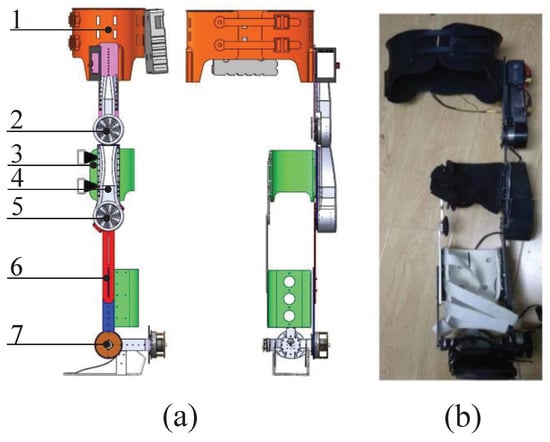
Figure 1.
The mechanical structure of the single-legged exoskeleton. (a) 3D model. 1. Waistband. 2. Hip joint. 3. Belt. 4. Thigh link. 5. Knee joint. 6. Shank link. 7. Ankle joint; (b) real model.
2.2. Acquisition and Communication System
The information acquisition system is composed by the motion capture sensor referred to as WSSS provided by Creasen High-Tech Co., Ltd. Shenyang, China and the self-made foot pressure sensor. The physical picture is shown in Figure 2. WSSS is a three-dimensional motion attitude measurement system based on MEMS technology that integrates a high-precision triaxial gyroscope, triaxial accelerometer and triaxial magnetic sensor. A low-power processor is used inside WSSS to return quaternion and Euler angles in real time, with angular resolution of 0.01 degree. The self-made foot pressure sensor is made of a thin film pressure sensor. According to the shape of a human foot and the pressure characteristics while walking [31,32], there are four pressure points that are set. The first, second, and third pressure points are near the first and second metatarsal bones, and the fourth pressure point is on the heel. In this paper, we divide the human walking cycle into four stages, namely landing transition period, support period, off-ground transition period and swing period. The walking state of the patient can be judged through the analysis of the stress on the four pressure points, as shown in Figure 3. Plantar pressure is an important indicator to evaluate patient movement status and predict patient movement intention [33]. Therefore, it is particularly important to establish the corresponding relationship between foot pressure and human walking gait characteristics.
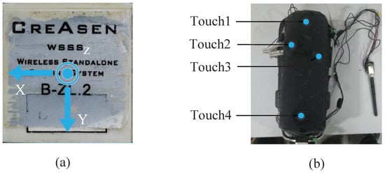
Figure 2.
The physical pictures of sensors.(a) WSSS sensor. (b) self-made foot pressure sensor.
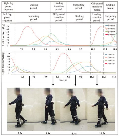
Figure 3.
The pressure changes at the four pressure points of the left and right feet during a gait cycle.
The flow chart of data communication system is shown in Figure 4.
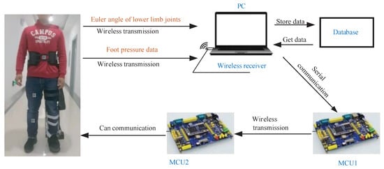
Figure 4.
The flow chart of the data communication system.
The MCU1 is the controller connected to the upper computer, and MCU2 is the controller connected to the single-legged exoskeleton. The patients wear the exoskeleton and sensors, which transmits the data of healthy leg joints and foot pressure collected by the sensor to the upper computer via a USB wireless receiver. The upper computer calculates the angle of the adjacent WSSS sensor coordinate system, and uses inverse kinematics to obtain and store the joint angles of the hip and knee. Then, these data are sent to MCU1 through serial port. The data transmission between MCU1 and MCU2 is completed by wireless transmission. The data received by MCU2 are internally settled according to the defined protocol, and a CAN bus is used to communicate with the actuator to realize motor control. The PID algorithm was used to complete motor control. According to the data feedback of the exoskeleton joint motor encoder, the closed-loop PID control is carried out to control the exoskeleton motion accurately. The PID control diagram is shown in Figure 5. In the figure, is the target angle of the joint motor, is the feedback angle of the joint motor, and is the current to the actuator calculated by the PID algorithm. It is worth mentioning that the upper computer still continuously receives the Euler angle and foot pressure of the healthy leg transmitted by the sensor, then works out the joint angle of the healthy leg in real time in the practical application stage of the exoskeleton robot. Then, the motion intention of the patient can be predicted based on the foot pressure, and the stride length and stride frequency of the gait data are adjusted by the walking characteristics recognized from the data of sensors fixed on the healthy leg. Finally, the adjusted joint angle is sent to the lower computer.
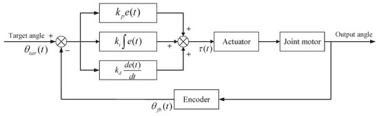
Figure 5.
The PID control diagram of the control of the exoskeleton motor.
3. Adaptive Adjustment Strategy
The adaptive adjustment strategy proposed in this paper is a kind of control method for which the exoskeleton robot can be adjusted in real time according to the user’s walking gait and the user’s walking habits. This paper describes the user walking gait by means of stride length and stride frequency. First, the curve fitting of the joint angle data of normal gait in a walking cycle is carried out, and then we need to find out the relationship between the curve equation and stride length and stride frequency. Through this correspondence, the stride length and stride frequency of the exoskeleton are adjusted to achieve the purpose of self-adaptation. The adaptive adjustment strategy is implemented by the Python program on the upper computer.
3.1. Joint Angle Fitting
The joint angle data of normal walking is collected through the WSSS sensor, and the data of one cycle is extracted, which can be seen in Figure 6. Then, the data of this cycle are fitted. In the experiment, we try to fit the curve of a polynomial (quadratic function, cubic function, quartic function, etc.), but the result is not ideal. For example, only one cubic function will result in a lower fitting degree of the function image, while only one fifth or sixth function will have a great fitting at the beginning but serious deviation at the end. Therefore, this paper fits the data with several lower order polynomials.
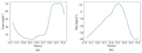
Figure 6.
The joint angle data of normal walking in one gait cycle. (a) knee joint. (b) hip joint.
Based on the above idea, the joint angle curve is divided into two sections according to time. The first section is represented as , and the second section is represented as . Then, the least square regression analysis method is used to fit the two sections of the curve respectively by a cubic polynomial. However, the two sections of the fitted curve cannot be smoothly connected; a cubic polynomial is selected to interpolate the two sections of the curve, which make the two sections of the curve be smoothly connected. Firstly, select 5–10 points on and , respectively, and take the n-th point on as the initial point of interpolation, and the m-th point on as the end point of interpolation. The selection of initial point and end point needs to satisfy the condition as follows:
where represents the initial point of the interpolation curve, and represents the end point of the interpolation curve. Then, the cubic equation of the intermediate connection curve can be solved through Formula (1).
By taking the joint angle data of the period selected previously into the above fitting method, the fitting function of knee joint and hip joint can be obtained as follows. The curve of the function is shown in Figure 7. The fitting function obtained is the benchmark for the subsequent stride length and stride frequency analysis.
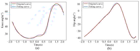
Figure 7.
The curve of the fitting function. (a) knee joint. (b) hip joint.
The curve fitting function of the hip joint is:
The curve fitting function of the knee joint is as follows:
where t represents time and represents joint angle. It can be seen from Figure 7 that the variation of joint angle after fitting is basically consistent with the original data and the connection is smooth.
3.2. Adaptive Adjustment Strategy
3.2.1. Parameterization of Fitting Equations
After the joint angle curve fitting is completed, three cubic polynomials are obtained to describe the angle data of a gait cycle. However, there will be different stride length and frequency in the whole walking process. In order to adapt to the gait characteristics of different people, it is necessary to find out the relationship between stride length and stride frequency and Formulas (2) and (3). The adaptive adjustment strategy proposed in this paper is realized through the above relations. Firstly, the fitting equation obtained in Section 3.1 is abstracted into a general cubic polynomial:
where t represents time, represents joint angle at time t, and A, B, C, and D represent known parameters, all of which are constants.
The idea of this algorithm is to stretch and shift the fitting curve. Among them, the stretch transformation up and down of the curve corresponds to the change of the motion amplitude of the exoskeleton robot, that is, the stride length. The stretching transformation left and right of the curve corresponds to the change of the motion frequency of the exoskeleton robot, that is, the stride frequency. Shifting the data curve up and down can change the initial angle of the exoskeleton robot motion. Shifting the data curve to the right or to the left can change the time characteristics of the data curve. Based on this idea, the formula of is obtained by parameterizing as follows:
where a, b, c, and d represent the four parameters added to the original curve equation. Formula (5) can be simplified to . By changing these four parameters, we can shift and stretch . Take the knee joint curve equation as an example to perform the stretching and shifting curve to verify the above assumption. We set the initial values of a, b, c, and d are 1, 0, 1, 0 respectively, which satisfies = . We follow the control variable principle for the more obvious contrast effect. Parameters a = 1.2, b = 1, c = 1.2 and d = 10 are respectively changed to obtain the curve comparison graphs before and after transformation, as shown in Figure 8.
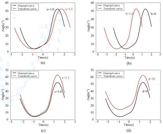
Figure 8.
The curve comparison graphs before and after transformation by setting parameters. (a) setting parameter a. (b) setting parameter b. (c) setting parameter c. (d) setting parameter d.
It can be seen from the figure, when parameter a = 1.2, that the transformed curve is stretched 1.2 times along the direction of the time axis in Figure 8a. When parameter b = 1, the transformed curve moves one unit to the left along the time axis in Figure 8b. When parameter c = 1.2, the transformed curve is stretched 1.2 times along the vertical axis in Figure 8c. When parameter d = 10, the transformed curve moves 10 units along the vertical axis in Figure 8d. Through the comparison of these curves, it is found that the curve influenced by parameter a is the stretching transformation along the time axis, which corresponds to the stride frequency. Parameter c affects the stretch transformation of the curve along the vertical axis, which corresponds to the stride length. Parameters b and d shift the curve along the time axis and the vertical axis, respectively. According to the above analysis, this assumption is verified to be effective. Therefore, the stride frequency and length can be changed by setting parameters a and c so that the walking gait is changed.
Because all the data are discrete in the actual control system, the next step is to discretize the continuous curve equation and explore how to combine the parameters of the equation with the sensor data in the control system so that the exoskeleton robot can automatically detect the changes of the stride length and stride frequency of the human body. The equations of about four parameters are established:
where m is the variable, is the function of the corresponding parameters a, b, c and d, and i = 1, 2, 3, 4.
We need to find the relationship between m and the parameters a, b, c, d, and change the value of indirectly by changing the value of m. The data need to be discretized in the actual control process, that is, time t is discontinuous, so
where n is the number of points selected in a gait cycle, and is the minimum interval between the points. Substitute Formula (7) into simplified Formula (5),
where is the angle value of the n-th point. Since the difference in walking gait is mainly caused by stride length and frequency, the parameters to be adjusted are a and c in real time. Formula (8) can be simplified as:
where parameters and are constants, while parameters a and c are variable.
The functions of parameters and are introduced mainly to adjust and correct the initial deviation value of sensor wearing because, when the sensor is strapped to the body, the sensor is not completely on a plane, and the y-axis of the sensor is not completely vertical downward. In the initial electrification phase, the initial angles of the human hip joint and knee joint are both zero. According to this characteristic, the fitting data can be directly translated up and down. The movement of the function image on the x-axis is to correct the time deviation, and all the extracted features of the gait cycle can be shifted around the zero of the x-axis. The advantage of this method is that the coefficient of joint angle fitting will be smaller, so that the rule of human movement can be better found.
After obtaining the parameter a for adjusting stride frequency and parameter c for adjusting stride length in the fitting equation, we need to find the relationship between parameters a, c and in Formula (10), so as to achieve the purpose of correcting stride length and stride frequency in real time:
3.2.2. Modification of Stride Frequency Parameter a
Parameter a is the parameter to adjust the motion frequency of the exoskeleton robot. For users, only information about foot pressure of the healthy leg is useful. Therefore, it is necessary to adjust the stride frequency of exoskeleton robot by the stride frequency of the healthy leg. Through the above research about the human walking rule, it can be seen that two legs are always in two opposite stages of the four stages during the walking process. The transition time of the healthy leg from the off-ground transition period to the end of the swing period is equal to the transition time of the exoskeleton robot from the landing transition period to the end of the support period. According to this characteristic, the motion frequency of exoskeleton robot is adjusted:
where represents the transition time of the healthy leg from the off-ground transition period to the swing period, K is the number of points selected from , and represents the stride frequency adjustment coefficient of the m-th gait. The stride length and frequency of the single-legged exoskeleton robot need to be adjusted according to the periodic symmetry of human motion [34]. In this paper, the stride length of the exoskeleton robot is adjusted according to the stride length of the healthy leg in a gait cycle. The stride length of human is collected in real time by an attitude sensor and a foot pressure information acquisition system.
3.2.3. Modification of Stride Length Parameter c
In this paper, the motion amplitude of hip joint and knee joint was calculated by collecting the angle of hip joint and knee joint from the landing transition stage to the next walking cycle. The motion amplitude coefficient is obtained by comparing with the standard data. Taking the adjustment of motion amplitude of a knee joint as an example, the adjustment method of motion amplitude of exoskeleton robot was studied:
where is the change coefficient of human motion amplitude in the m-th gait cycle, is the motion amplitude of humans during the first gait cycle, and represents the amplitude of the human motion during the m-th gait cycle.
The exoskeleton amplitude of the current cycle can be predicted by the healthy leg amplitude of the previous cycle. Therefore, the exoskeleton stride length can be adjusted by attaching different weights to the stride length coefficient. The motion amplitude coefficient is larger, and the weight is smaller:
where represents the weight of stride length coefficient .
In this experiment, we extracted the gait of the previous two cycles on the healthy leg to predict the exoskeleton gait of the current cycle. Therefore, n = 2 is substituted into Formula (13) to obtain the stride length coefficient equation of the experiment as follows:
where c is the stride length coefficient of the current period, and respectively represent the maximum and minimum stride length coefficients of the previous two cycles, and and are the weight coefficients. The optimal weight coefficient = 0.3 and = 0.7 are obtained through experiments with different weight coefficients. The selection of stride length coefficient weight not only ensures that the exoskeleton can accurately follow the gait of the healthy leg when the stride length is changed subjectively, but also reduces the influence of unexpectedly large or small steps in the whole walking process. Based on the above analysis, the exoskeleton robot can predict the walking gait of the current cycle in real time based on the gait data of the previous two cycles on the healthy leg. However, during the first two cycles of the exoskeleton, there were no walking data of the healthy leg. Therefore, in this experiment, the gait data of healthy people obtained in advance are used as sample data in the first two cycles, so that the exoskeleton adopts a fixed gait to realize walking in the first two cycles.
The above part is the adaptive adjustment strategy for walking characteristics proposed in this paper. The parameter a and the parameter c realize the adjustment of stride length and stride frequency. This article is aimed at patients with hemiplegia, that is, one leg is healthy and one leg is diseased. Compared with the traditional walking mode of exoskeleton, the gait adjustment strategy proposed in this paper can make full use of the characteristics of hemiplegic patients. The exoskeleton can learn the gait of healthy legs in real time, so that patients can walk naturally. The advantages of this method are verified by walking experiments.
4. Experiment
This chapter mainly introduces the experiment of using a single-legged exoskeleton robot. In this section, the experimental conditions and process are explained in detail. Finally, the experimental data are analyzed according to the obtained experimental results.
4.1. Experimental Process
In order to verify the effectiveness of the adaptive adjustment strategy of gait characteristics, five men were selected as experimental subjects to complete the walking experiment of wearing an exoskeleton. The relevant information of the experimental subjects is shown in Table 1. As shown in Figure 4, the lower limb exoskeleton is worn on the left leg, and WSSS sensor and planta pressure sensor are worn on the right leg. The assisted walking experiment of wearing an exoskeleton was completed on the horizontal ground. With the exoskeleton power on and the upper computer program running, the subject will be able to walk with the assistance of the exoskeleton. Moreover, the program of the upper computer and the structure design of exoskeleton can limit motor torque and the range of joint angle, so as to ensure the safety of the subject. Figure 9 shows the actual walking gait picture of the subject taken from multiple angles during the experiment. The time below the picture is the time point taken during the actual walking.

Table 1.
The parameters of five subjects.
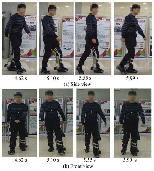
Figure 9.
A multi-angle screenshot of the subject actual walking gait during the experiment.
The exoskeleton wearing experiment was completed in three stages. In the first stage, stride frequency parameter a = 1 was set, and stride length parameter c was corrected in real time based on healthy leg stride length to verify the adjustment ability of stride length parameter c. In the second stage, the stride length parameter c = 1 was set, and the stride frequency parameter a was corrected in real time based on the healthy leg stride frequency to verify the adjustment ability of stride frequency parameter a. In the third stage, stride frequency parameters a and stride length parameters c were modified in real time based on healthy leg gait to verify the effectiveness of the adaptive adjustment strategy for walking characteristics proposed in this paper. All five subjects participated in the three parts of the experiment, and then the specific implementation method of the experiment was introduced. Firstly, WSSS sensors and foot pressure sensors are used to collect and store the healthy leg joint angle and foot pressure of the subject in the experiment. On the one hand, the data are used to determine the beginning and end of the walking cycle; on the other hand, it is used as a standard for later analysis and evaluation. The exoskeleton walks in the first two cycles according to the collected standard gait data of the healthy person. Starting from the third cycle, the sensor is used to collect and store the walking data of the healthy leg in real time. The data are transmitted wirelessly to the upper computer to predict the gait of the exoskeleton, and then the predicted data are sent to the MCU2 for the control of the exoskeleton motor. Finally, comparing the healthy leg joint angle, the exoskeleton target joint angle and actual joint angle to observe whether the changes in the peak value and frequency of the exoskeleton joint angle can follow the changes of healthy leg joint angle during the subject walking.
4.2. Analysis of Experimental Data
4.2.1. Adjustment Experiment of Stride Length Parameter c
Firstly, the experimental results of setting stride frequency parameter a = 1 and correcting stride length parameter c in real time are discussed. Since the experimental results of the five subjects had the same conclusion, the experimental results of one of them were selected for analysis. Figure 10 is the stride length adjustment curve of one of the subjects. In the figure, “leg hip” and “leg knee” are respectively the angle change curves of the hip joint and knee joint of the healthy leg of the subject. “tar hip” and “tar knee” are respectively the target curves of the hip joint and knee joint of the exoskeleton calculated based on the stride length of the healthy leg. As can be seen from the figure, the period of the target curve is fixed, and the amplitude changes with the change of the healthy leg. The amplitude of the healthy leg’s hip and knee angle gradually increased, as did the amplitude of the exoskeleton’s joint angle before 15 s. In addition, the amplitude of the hip and knee angle of the healthy leg gradually decreased, as did the amplitude of the joint angle of the exoskeleton after 15 s.
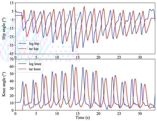
Figure 10.
Stride length adjustment curve.
In order to better reflect the amplitude following effect, the relative error value is defined to quantitatively analyze the amplitude tracking performance. The error calculation is shown in Formula (15):
where is the joint amplitude of the exoskeleton in one cycle, and is the joint amplitude of the healthy leg in the same cycle. Figure 11 shows the line chart of relative error of stride length tracking of five subjects. As can be seen from the figure, the stride length tracking error of all five subjects was within ±5%, indicating that the real-time modification of stride length parameter c while walking enabled the exoskeleton to track the stride length changes of the healthy leg well.
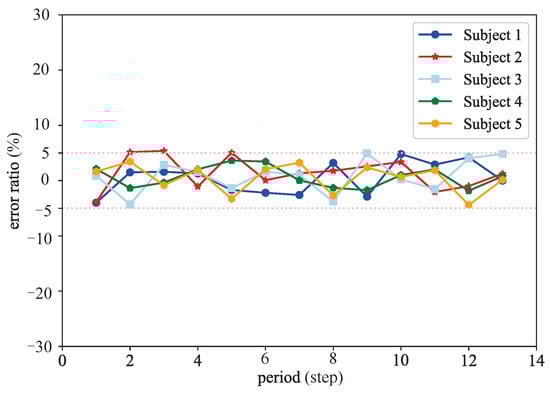
Figure 11.
Stride length tracking error.
4.2.2. Adjustment Experiment of Stride Frequency Parameter a
This section discusses the experimental results of setting stride length parameter c = 1 and modifying stride frequency parameter a in real time. Figure 12 is the stride frequency adjustment curve of one of the subjects. The experimental results of this part are to verify the adaptive adjustment ability of stride frequency. The red curve in the figure is the adaptive adjustment of the joint angle curve. The amplitude of this curve remains fixed, and the period of the curve is adjusted accordingly with the period change of the healthy leg joint angle curve (blue curve). Observing the curve in the figure, from 7 s to 17 s, the walking period is about 5 s, and the stride frequency is the lowest. From 17 s to 31 s, the stride frequency increased relatively. After 31 s, the stride frequency gradually increases, and the last period is about 2 s, and the period frequency is the highest.
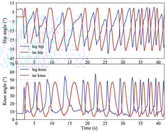
Figure 12.
Stride frequency adjustment curve.
In order to better reflect the following effect of stride frequency, the relative error value is defined to quantitatively analyze the tracking performance of stride frequency. The error calculation is shown in Formula (16):
where is the period of one step of exoskeleton walking, and is the period of one step of healthy leg walking. Figure 13 shows the line chart of relative error of stride frequency tracking of five subjects. The walking period following error of the five subjects was within ±7%; that is to say, the walking speed of the exoskeleton was consistent with that of the healthy leg, which verified the effect of parameter a on adjusting the stride frequency.
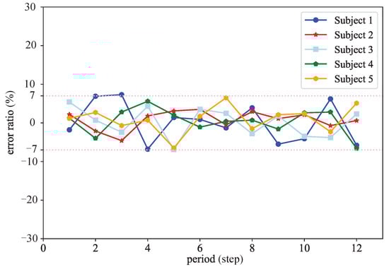
Figure 13.
Stride frequency tracking error.
4.2.3. Adaptive Adjustment Experiment of Stride Frequency and Length
The above two experiments discussed the effect of adjusting parameter a and c, respectively. This section discussed the ability to adjust stride length and stride frequency simultaneously for walking characteristics. The angle curves of the knee joint and hip joint were obtained by comparing the joint angle data of the healthy leg and the exoskeleton. The joint angle curve of one of the subject is shown in Figure 14. In the figure, “exo hip” and “exo knee” are respectively the actual angle change curves of the exoskeleton hip joint and knee joint, respectively. According to the curve obtained from the experiment, it can be seen that the target joint angle (red line) is basically consistent with the actual exoskeleton joint angle (dotted line), indicating that the motor control method selected in the paper can achieve accurate position control. In addition, it can also be seen from the curve that the first two cycles of the exoskeleton walk with a fixed gait; the joint angle changes consistently and is not affected by the gait of the healthy leg. Starting from the third cycle, because a healthy leg gait of the subjects was deliberately altered, the healthy leg joint curve has a certain degree of change in each cycle, the adaptive adjustment curve (blue line) changes are similar to the healthy leg, which shows that the proposed adaptive adjustment strategy can make the exoskeleton adapt and follow the gait of the healthy leg well.
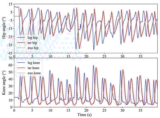
Figure 14.
The curves of the adaptive adjustment experiment.
At present, most research on exoskeletons use a fixed gait to assist walking with both legs. This kind of exoskeleton is more suitable for patients with a two-leg disease. Since neither of the patient’s legs can be controlled voluntarily, there is no large interaction force with the exoskeleton. However, double-leg exoskeletons are not suitable for hemiplegic patients because patients have one leg that can move by themselves. Wearing a double-leg exoskeleton will generate a large interactive force with the healthy leg. The healthy legs are affected by the exoskeleton while moving voluntarily, thus interfering with the normal walking of the patient. The auxiliary effect of the double-leg exoskeleton on the hemiplegic patients is poor. In addition, the fixed gait method often used in exoskeleton research is not friendly to the walking habits of patients. In this paper, a set of experiments to assist walking with a fixed gait method are carried out, and the experimental results are shown in Figure 15. In the figure, the stride length and stride frequency of the healthy leg (blue line) in the figure change, while the exoskeleton (red line) always maintains a fixed stride length and stride frequency. This method cannot make good use of the patient’s healthy leg, and the patient does not feel engaged during the whole walking process. More importantly, it will lead to asymmetrical walking on both legs, which increases the instability of walking and makes it easier for the patient to fall. Compared to Figure 14, the exoskeleton maintains a gait consistent with the patient’s healthy leg, thereby ensuring walking symmetry and stability. Compared with Figure 14, the exoskeleton maintains the same gait as the patient’s healthy legs, thereby ensuring the symmetry and stability of walking; at the same time, it increases the patient’s sense of participation, enabling the patient to independently adjust the stride length and stride frequency during walking.
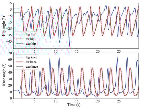
Figure 15.
The curves of the fixed gait experiment.
The above experiments verify the effectiveness and practicability of the adaptive adjustment strategy for walking characteristics. This method makes full use of the characteristics of hemiplegia patients, so that patients can walk more naturally. The paper provides a new idea and theoretical basis for the subsequent design of the single-legged exoskeleton control strategy, namely, to copy the gait characteristics of the healthy leg to the exoskeleton, so that the exoskeleton can maintain the same gait as the healthy leg.
5. Conclusions
In this paper, an adaptive adjustment strategy for walking characteristics for the single-legged exoskeleton robot is proposed. The algorithm uses the user’s own walking data to predict the joint angle data of the exoskeleton in order to achieve adaptive adjustment. The joint angles of the healthy legs under the natural gait are collected, and then the angular fitting equation about time is obtained by the least square regression method to fit. Search for the effect of stride frequency and stride length on the fitting equation to control the variation of exoskeleton joint angle and then transmit processed data to the exoskeleton in real time to move. The rationality of the design of the exoskeleton robot and the effectiveness of the adaptive adjustment strategy have been verified with the experiment. Due to the limitation of conditions, the experimental object selected this time is a healthy person. In the future, we will use this exoskeleton robot for the experiment of hemiplegia patients, and more complex experimental scenarios such as going up and down stairs and going up and down hills will be attempted to better improve the single-legged exoskeleton.
Author Contributions
Z.L. and C.L. conceived the proposed idea, D.C. collected and sorted out the data. H.D. developed the mechanical structure. D.Y. and Q.C. designed the control system. D.Y. and Q.C. did the experiment and got the results. Z.L. and D.Y. discussed the results and wrote the paper. All authors have read and agreed to the published version of the manuscript.
Funding
This research is supported by the National Natural Science Foundation of China (51505069), and the Fundamental Research Funds for the Central Universities (N182410007-05).
Institutional Review Board Statement
The study was conducted in accordance with the Declaration of Helsinki, and approved by the Biological and Medical Ethics Committee of Northeastern University(NEU-EC-2022B001S).
Informed Consent Statement
Informed consent was obtained from all subjects involved in the study.
Data Availability Statement
The data presented in this study are available on request from the corresponding author on reasonable request.
Conflicts of Interest
The authors declare that there is no conflict of interest regarding the publication of this paper.
References
- Lenzi, T.; Cempini, M.; Hargrove, L.; Kuiken, T. Design, development, and testing of a lightweight hybrid robotic knee prosthesis. Int. J. Robot. Res. 2018, 37, 953–976. [Google Scholar] [CrossRef]
- Zhou, L.B.; Chen, W.H.; Chen, W.J.; Bai, S.P.; Zhang, J.B.; Wang, J.H. Design of a passive lower limb exoskeleton for walking assistance with gravity compensation. Mech. Mach. Theory 2020, 150, 103840. [Google Scholar] [CrossRef]
- Du, G.; Chen, M.; Liu, C.; Zhang, B.; Zhang, P. Online robot teaching with natural human-robot interaction. IEEE Trans. Ind. Electron. 2018, 65, 9571–9581. [Google Scholar] [CrossRef]
- Li, Z.J.; Su, C.Y.; Wang, L.Y.; Chen, Z.T.; Chai, T.Y. Nonlinear disturbance observer- based control design for a robotic exoskeleton incorporating fuzzy approximation. IEEE Trans. Ind. Electron. 2015, 62, 5763–5775. [Google Scholar] [CrossRef]
- Lu, R.Q.; Li, Z.J.; Su, C.Y.; Xue, A. Development and learning control of a human limb with a rehabilitation exoskeleton. IEEE Trans. Ind. Electron. 2014, 61, 3776–3785. [Google Scholar] [CrossRef]
- Li, Z.J.; Kang, Y.; Xiao, Z.Y.; Song, W.G. Human-robot coordination control of robotic exoskeletons by skill transfers. IEEE Trans. Ind. Electron. 2017, 64, 5171–5181. [Google Scholar] [CrossRef]
- Capitani, S.L.; Bianchi, M.; Secciani, N. Model-based mechanical design of a passive lower-limb exoskeleton for assisting workers in shotcrete projection. Meccanica 2021, 56, 195–210. [Google Scholar] [CrossRef]
- Veneman, J.F.; Kruidhof, R.; Hekman, E.E.G.; Ekkelenkamp, R.; Asseldonk, E.H.F.V.; van der Kooij, H. Design and Evaluation of the LOPES Exoskeleton Robot for Interactive Gait Rehabilitation. IEEE Trans. Neural Syst. Rehabil. Eng. 2007, 15, 379–386. [Google Scholar] [CrossRef] [Green Version]
- Sankai, Y. HAL: Hybrid Assistive Limb Based on Cybernics. In Proceedings of the 13th International Symposium on Robotics Research (ISSR), Berlin/Heidelberg, Germany, 26–29 November 2010; pp. 25–34. [Google Scholar] [CrossRef]
- Kawamoto, H.; Sankai, Y. Comfortable power assist control method for walking aid by HAL-3. In Proceedings of the IEEE International Conference on Systems, Man and Cybernetics, Yasmine Hammamet, Tunisia, 6–9 October 2002; Volume 4, p. 6. [Google Scholar] [CrossRef]
- Lee, S.; Sankai, Y. Power assist control for leg with HAL-3 based on virtual torque and impedance adjustment. In Proceedings of the IEEE International Conference on Systems, Man and Cybernetics, Yasmine Hammamet, Tunisia, 6–9 October 2002; Volume 4, p. 6. [Google Scholar] [CrossRef]
- Kawamoto, H.; Lee, S.; Kanbe, S.; Sankai, Y. Power assist method for HAL-3 using EMG-based feedback controller. In Proceedings of the SMC’03 Conference, 2003 IEEE International Conference on Systems, Man and Cybernetics, Conference Theme–System Security and Assurance (Cat. No.03CH37483), Washington, DC, USA, 8 October 2003; pp. 1648–1653. [Google Scholar] [CrossRef]
- Talaty, M.; Esquenazi, A.; Briceño, J.E. Differentiating ability in users of the ReWalkTM powered exoskeleton: An analysis of walking kinematics. In Proceedings of the 2013 IEEE 13th International Conference on Rehabilitation Robotics (ICORR), Seattle, WA, USA, 24–26 June 2013; pp. 1–5. [Google Scholar] [CrossRef]
- Neuhaus, P.; Kazerooni, H. Design and control of human assisted walking robot. In Proceedings of the 2000 ICRA, Millennium Conference, IEEE International Conference on Robotics and Automation, Symposia Proceedings (Cat. No.00CH37065), San Francisco, CA, USA, 24–28 April 2000; pp. 563–569. [Google Scholar] [CrossRef]
- Li, M.T.; Deng, J.; Zha, F.S.; Qiu, S.Y.; Wang, X.; Chen, F. Towards Online Estimation of Human Joint Muscular Torque with a Lower Limb Exoskeleton Robot. Appl. Sci. 2018, 8, 1610. [Google Scholar] [CrossRef] [Green Version]
- Contreras-Vidal, J.L.; Bhagat, N.A.; Brantley, J.; Cruz-Garza, J.G.; He, Y.; Manley, Q.; Nakagome, S.; Nathan, K.; Tan, S.H.; Zhu, F.; et al. Powered exoskeletons for bipedal locomotion after spinal cord injury. Int. J. Neural Eng. 2016, 13, 031001. [Google Scholar] [CrossRef]
- Yang, Y.; Ma, L.; Huang, D. Development and Repetitive Learning Control of Lower Limb Exoskeleton Driven by Electrohydraulic Actuators. IEEE Trans. Ind. Electron. 2017, 64, 4169–4178. [Google Scholar] [CrossRef]
- Tang, L.; Shi, P. Design and analysis of a gait rehabilitation cable robot with pairwise cable arrangement. Int. J. Mech. Sci. Technol. 2021, 35, 3136–3170. [Google Scholar] [CrossRef]
- Guo, W.; Qiu, S.Y.; Zha, F.S.; Deng, J.; Wang, X.; Chen, F. A novel active balance assistive control strategy based on virtual stiffness model of XCoM. Assem. Autom. 2019, 40, 132–142. [Google Scholar] [CrossRef]
- Qiu, S.Y.; Guo, W.; Wang, P.F.; Chen, F.; Zha, F.S.; Wang, X.; Deng, J. A Unified Active Assistance Control Framework of Hip Exoskeleton for Walking and Balance Assistance. In Proceedings of the 2019 IEEE/RSJ International Conference on Intelligent Robots and Systems (IROS), Macau, China, 3–8 November 2019; pp. 8185–8192. [Google Scholar] [CrossRef]
- Gardner, A.D.; Potgieter, J.; Noble, F.K. A review of commercially available exoskeletons’ capabilities. In Proceedings of the 2017 24th International Conference on Mechatronics and Machine Vision in Practice (M2VIP), Auckland, New Zealand, 21–23 November 2017; pp. 1–5. [Google Scholar] [CrossRef]
- Esquenazi, A.; Talaty, M.; Jayaraman, A. Powered Exoskeletons for Walking Assistance in Persons with Central Nervous System Injuries: A Narrative Review. PM&R 2017, 9, 46–62. [Google Scholar] [CrossRef]
- Qiu, S.Y.; Guo, W.; Caldwell, D.; Chen, F. Exoskeleton Online Learning and Estimation of Human Walking Intention Based on Dynamical Movement Primitives. IEEE Trans. Cogn. Dev. Syst. 2020, 13, 67–79. [Google Scholar] [CrossRef]
- Kawamoto, H.; Hayashi, T.; Sakurai, T.; Eguchi, K.; Sankai, Y. Development of single leg version of HAL for hemiplegia. In Proceedings of the 2009 Annual International Conference of the IEEE Engineering in Medicine and Biology Society, Minneapolis, MN, USA, 3–6 September 2009; pp. 5038–5043. [Google Scholar] [CrossRef]
- Hassan, M.; Kadone, H.; Suzuki, K.; Sankai, Y. Wearable Gait Measurement System with an Instrumented Cane for Exoskeleton Control. Sensors 2014, 14, 1705–1722. [Google Scholar] [CrossRef] [Green Version]
- Moon, D.H.; Kim, D.; Hong, Y.D. Development of a Single Leg Knee Exoskeleton and Sensing Knee Center of Rotation Change for Intention Detection. Sensors 2019, 19, 3960. [Google Scholar] [CrossRef] [Green Version]
- Moon, D.H.; Kim, D.; Hong, Y.D. Intention Detection Using Physical Sensors and Electromyogram for a Single Leg Knee Exoskeleton. Sensors 2019, 19, 4447. [Google Scholar] [CrossRef] [Green Version]
- Shi, D.; Zhang, W.; Zhang, W.; Ding, X. A Review on Lower Limb Rehabilitation Exoskeleton Robots. Chin. J. Mech. Eng. 2019, 32, 1–11. [Google Scholar] [CrossRef] [Green Version]
- McCain, E.M.; Dick, T.J.; Giest, T.N.; Nuckols, R.W.; Lewek, M.D.; Saul, K.R.; Sawicki, G.S. Mechanics and energetics of post-stroke walking aided by a powered ankle exoskeleton with speed-adaptive myoelectric control. J. Neuroeng. Rehabil. 2019, 16, 57. [Google Scholar] [CrossRef]
- Zhang, Y.; Li, S.; Zhou, X. Recurrent-Neural-Network-Based Velocity-Level Redundancy Resolution for Manipulators Subject to a Joint Acceleration Limit. IEEE Trans. Ind. Electron. 2019, 66, 3573–3582. [Google Scholar] [CrossRef]
- Hassan, M.; Kadone, H.; Suzuki, K.; Sankai, Y. Exoskeleton robot control based on cane and body joint synergies. In Proceedings of the 2012 IEEE/RSJ International Conference on Intelligent Robots and Systems, Vilamoura, Portugal, 7–12 October 2012; pp. 1609–1614. [Google Scholar] [CrossRef]
- Petrović, S.; Devedžić, G.; Ristić, B.; Matić, A.; Stojanović, R. Foot pressure distribution and contact duration pattern during walking at self-selected speed in young adults. In Proceedings of the 2013 2nd Mediterranean Conference on Embedded Computing (MECO), Budva, Serbia, 15–20 June 2013; pp. 172–175. [Google Scholar] [CrossRef]
- Tran, A.V.; Zhang, X.; Zhu, B. The Development of a New Piezoresistive Pressure Sensor for Low Pressures. IEEE Trans. Ind. Electron. 2018, 65, 6487–6496. [Google Scholar] [CrossRef]
- Guizzo, E.; Goldstein, H. The rise of the body bots [robotic exoskeletons. IEEE Spectr. 2005, 42, 50–56. [Google Scholar] [CrossRef]
Publisher’s Note: MDPI stays neutral with regard to jurisdictional claims in published maps and institutional affiliations. |
© 2022 by the authors. Licensee MDPI, Basel, Switzerland. This article is an open access article distributed under the terms and conditions of the Creative Commons Attribution (CC BY) license (https://creativecommons.org/licenses/by/4.0/).