Article

Constraint Definition for Gripper Selection and Grasp Planning for Robotic Assembly Using Product Manufacturing Information from STEP AP242Ed2 Files

by
Shafi Khurieshi Mohammed
1,*,
Mathias Hauan Arbo
2 and
Lars Tingelstad
1
1
Department of Mechanical and Industrial Engineering, Norwegian University of Science and Technology (NTNU), 7034 Trondheim, Norway
2
Research Scientist, SINTEF Manufacturing AS, 7031 Trondheim, Norway
*
Author to whom correspondence should be addressed.
Machines 2022, 10(12), 1230; https://doi.org/10.3390/machines10121230
Submission received: 12 September 2022 / Revised: 27 November 2022 / Accepted: 13 December 2022 / Published: 16 December 2022
(This article belongs to the Topic Robotics and Automation in Smart Manufacturing Systems)

Abstract

:
This article uses the Product Manufacturing Information (PMI) from STEP AP242 neutral files for gripper selection and grasp planning in a robotic assembly operation. The PMI, along with the part geometry and dimensions, are used in identifying various handling features of the parts and selecting an appropriate gripper. The required PMI, like material, volume, surface finish, threading and coating information, are added to the STEP AP242 files. The PMI is semantically included in the STEP files following the Model Based Definition (MBD) methodology. Two methods are described to add the PMI to the STEP files, one using a custom string and another using the standard entities defined in ISO 10303 AP242: 2020 standard. The entire process is demonstrated in a use case.

1. Introduction

Industrial grippers are crucial in many types of equipment like NC and special purpose machines, fixed automation, workpiece turrets and industrial manipulators [1,2]. The problem of robotic grippers is not new [3], but with the increasing adoption of robotic applications under Industry 4.0 [4], their importance is increased as they are the essential tool in many industrial operations like material handling [2]. Grippers are an essential component for the success of robotic assembly operation [5] as they affect both the cost and time of automation [6]. Hence, selecting an appropriate gripper and proper grasp planning will increase the successful completion of assembly operations with less time and lower cost.
The gripper selection and grasp planning is critical in the case of small and medium enterprises (SMEs) as they handle significant product variations and lower production volumes compared to mass production. As the product design changes, the SME needs to make the gripper selection and grasp planning for each change, which results in increased time and cost required for robotic assembly. The gripper selection and grasp planning process can be improved using product information. Product information is made available for all the stakeholders and downstream operations by adopting the Digital Thread (DT) methodologies as per Industry 4.0.
Mohammed et al. [7] used a method to add welding information semantically to the STEP files. This paper extends that method to include relevant PMI to the STEP AP242 Ed2 files and reuse it to identify the constraints for grasp planning. We also identify the information required for gripper selection and grasp planning from the existing literature and how this information can be included in the STEP AP242 files as per the latest industry standards. A method to extract the relevant information from the STEP files and identify the constraints for gripper selection and grasp planning is proposed. This process is demonstrated using a motor assembly use case.
The paper is structured as follows. Section 2 describes the gripping process and information needed for gripper selection and grasp planning from the existing literature. Section 3 presents the methodology of Model Based Definition (MBD) and the STEP AP242 standard is described in Section 4. Section 5, Section 6 and Section 7 demonstrate how surface finish and other PMI can be added to the STEP AP242 files. Section 8 describes the process of extracting the constraint information from the STEP AP242 files and the process is demonstrated using a use case. The concluding remarks are presented in Section 9.

2. Robotic Gripping

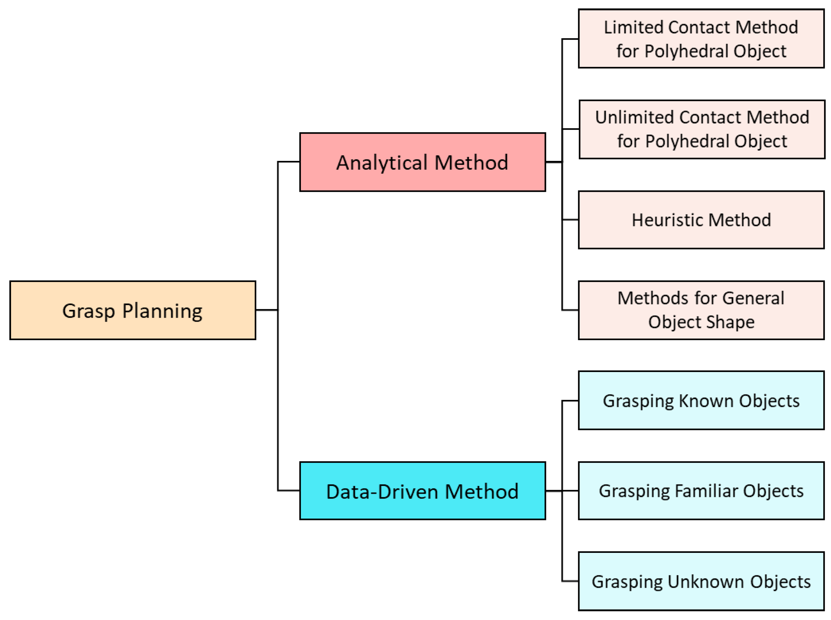
Successful adoption of automatic assembly systems depends on the capabilities of the grippers [1]. The gripping problem is one of the critical issues in the industrial assembly and part handling process. The grasp planning processes are classified into analytical and data-driven methods [8,9] as shown in Figure 1. Analytical methods are based on kinematic and dynamic models of grasp problem and the data-driven methods are based on machine learning techniques. Carvalho de Souza et al. [10] classified the data-driven methods by separating the deep learning methods from the rest of the machine learning methods. Kleeberger et al. [11] presented a comparison of various vision-based learning methods of grasp planning for handling rigid, articulated and deformable objects.

2.1. Gripper Performance and Selection

The grasp planning and gripper selection depend on several factors, but most are related to the objects being handled. As the gripper directly comes in contact with the parts during handling and assembly, their function and working envelope depend on the object’s properties. The parameters that influence the selection and functioning of grippers are well established in the literature [5,12,13,14].
As per Owen [12], the function of the gripper is limited by
  • Static force;
  • Dynamic force;
  • Part geometry.
Birglen et al. [15] presented a comparison of the two-finger parallel industrial grippers from various gripper manufacturers. They used characteristics like force, stroke, gripper weight and C-factor for comparing the different out-of-shelf grippers. C-factor is a measure that enables the comparison of grippers of different sizes and designs. It is calculated by multiplying the gripper’s stroke length by the ratio between the force and weight [2]. The object size, shape and material properties determine the selection of a gripper with appropriate force, stroke and C-factor.
Lotter [5] divided the object parameters that affect the handling tasks into characteristics and behavior. Object characteristics included geometry, size, mating/locking features, holes and physical properties such as material and temperature. Behavior parameters are further divided into stationary behavior that include positional stability and transfer behavior. These parameters are derived for both fixed and robotic automation. Some of these parameters are not relevant for robotic gripping, like stackability.
Fantoni et al. [14] identified the relevant parameters for gripper selection from the Design for Assembly principles. These parameters were grouped as object and operation parameters. The object parameters included both physical and geometric properties of the object and the operation parameters included the factors related to feeding, handling and placing.

2.2. Grasp Planning Using CAD

The closure of grasp in analytical methods is generally classified into two types depending on the method of constraints.
Force-closure Grasps The grasp is known as force-closure if the object is held in position by the gripper by applying force and moment at the contact points [16].
Form-closure Grasps Form-closure is achieved by selecting the contact points such that the object is constrained without applying any frictional forces or moments [17,18].
Other forms of grasps like partial form-closure are also available in the literature [18].
The analytical methods of grasp planning use the part shape, features, material and surface conditions in selecting the contact points and estimating the forces to achieve a successful grasp. The data-driven methods also depend on the earlier knowledge of the object’s shape or similarity with a known shape. When the object shape is entirely unknown, the data-driven methods use sensor data to understand the object shape [8]. Even the data-driven methods benefit from the previous knowledge of the object geometry and increase the grasp success [10].
Analytical methods are more appropriate for industrial applications than the data-driven methods [9]. The grasp planning can benefit from using the CAD models of the parts being handled and assembled. Kleeberger et al. [19] demonstrated that the success rate of data-driven methods is increased by using object geometry either from CAD models or point clouds. Many researchers used part geometry for grasp planning [20]. van Bruggen [21] described a method for identifying constraints of part features/surfaces unsuitable for gripping. Miller et al. [22] used primitive shapes like spheres, cylinders, cones and boxes for identifying initial grasp points and the grasp is simulated to arrive at the best option.
Schmalz et al. [23] presented a method for dimensioning grippers using part geometry from STEP files. Somani [24] combined CAD data with vision sensors for pose estimation and defining constraints for bin-picking tasks.
This paper considers only the physical and geometric object properties and how these parameters can be retrieved from the part design data for robotic applications. This paper also uses assembly constraints and threading information for defining constraints for grasp planning. The following key object parameters [1,14,25]:
  • Dimensional size
  • Material: strength, hardness, density
  • Weight
  • Surface texture
  • Special coatings
  • Thread information [21]
  • Assembly constraints and mating information
  • Center of gravity
  • Shape
  • Part features: holes, surfaces

3. Model-Based Definition (MBD)

The 3D CAD models are prepared by the designers during the design phase of the product life cycle. These 3D models are used to prepare the 2D manufacturing drawings. The manufacturing drawings have the complete product definition in terms of 2D geometry, dimensions and other PMI. Hence, the 2D manufacturing drawings are the single source of product definition and are used as input to all other downstream operations in the product life cycle. Manual effort is needed to read and recreate the operation-specific information from the manufacturing drawings at each downstream operation. The reinterpretation and recreation of data on the manufacturing shopfloor may result in human errors leading to part quality issues that, in turn, result in increased time-to-market and production costs. The manual intervention can be avoided by directly using the product data in the downstream operations. The direct reuse of product definition is facilitated by adopting a Model-Based Definition (MBD) methodology.
In the MBD methodology, the PMI is directly added to the features of the 3D CAD model during the design stage rather than preparing a separate 2D manufacturing drawing. Hence, the 3D model becomes the master source of product information carrying the product geometry, critical dimensions, GD&T, surface finish and all other information required by the downstream operations [26,27]. Figure 2 shows a 3D CAD model of a motor end plate with all the PMI attached to its features along with title-block information like part number, material and release date. MBD is the building block of product information that enables the establishment of DT in a connected Model Based Enterprise (MBE). Many downstream operations like NC machining and automated inspection [28] can reuse the product information directly from the MBD without manual intervention. Goher et al. [29] recorded many state-of-the-art applications of MBD.
The product information can be added to the 3D model as presentation PMI or semantic PMI. The presentation PMI serves the purpose of visualizing PMI on a 3D model. This type of PMI defeats the purpose of MBD as it requires human intervention to read and reinterpret the product data from the 3D model. Semantic PMI can be read and interpreted using computer programs. It serves the purpose of MBD by realizing the goal of reducing or eliminating human involvement in data recreation at the downstream manufacturing operations.
Another aspect related to the product definition is the problem of sharing it with downstream operations and other stakeholders like sub-contractors. The designers can share the MBD with the manufacturing teams in the native CAD format in which they were created. However, in this case, all the stakeholders require access and expertise to use the same commercial CAD software. Many SMEs cannot afford to purchase the licenses of the CAD software used by the original equipment manufacturers (OEMs) to whom they supply. Hence, the need for a neutral exchange format that can be used to share product definitions to all the stakeholders across the extended enterprise. STEP AP242 neutral file format matches the requirements for sharing the MBD as it can capture the PMI along with the product geometry. A brief description of STEP AP242 is provided in the following section.

4. STEP AP242

The Ssandard for the Exchange of Product Model Data (STEP) is the standard for product data representation and exchange extensively used in the industry. STEP AP242 is the latest member of the STEP-family of ISO (International Standards Organization) standards 10303: Automation systems and integration–Product data representation and exchange. The application protocol AP242: Managed model–based 3D engineering is defined to fulfill the needs of capturing and exchanging MBD [30]. The first edition of AP242, released in 2014, replaced the earlier application protocols AP203 (configuration controlled 3D designs of mechanical parts and assemblies) and AP214 (core data for automotive mechanical design processes) [31,32]. The latest (second) edition of this Application Protocol (AP) was in 2020 [33]. With the increasing digitalization as part of Industry 4.0 processes, the significance and use of STEP AP242 are increasing. STEP AP242 is used for various applications like automated tolerance analysis [34], CAD/CAE integration and smart manufacturing [35,36,37].
STEP AP242 facilitates the creation of MBD as per ASME Y14.41–2019: Digital Product Definition Data Practices [38] standard. Both presentation and semantic PMI can be added to the STEP AP242 files. Only semantic PMI is used in the current paper as presentation PMI is not suitable for robot programming and constraint definition. STEP AP242 files can carry the following product information.
Geometry STEP files capture the exact product geometry that can be extracted and used to identify various features of the part.
Assembly Information The information about the product structure and assembly constraints are part of STEP AP242 standards. This information is used to identify the relative positions of components in an assembly and is used by Mohammed et al. [39] to define the robot motion constraints for assembly.
Critical Dimensions and GD&T The critical-to-quality dimensions and the GD&T information can be directly added to the relevant part features in a STEP AP242 file. The information can be used to extract the sizes and locations of assembly features and estimate possible deviations from the nominal design values as described by Mohammed et al. [40].
Annotations STEP AP242 enables the addition of other necessary PMI such as surface finish, thread specifications and welding information as annotations. Mohammed et al. [7] added the welding annotations to the weld seams using Unicode strings to the STEP AP242 files.
Properties The product properties like material, weight, bounding box and other metadata can be included in the STEP AP242 files and reused in the automation of handling and packaging.
Notes Text annotations can be added to the STEP AP242 files to include tool or process-related information needed in the downstream manufacturing operations.
This paper deals with the addition and extraction of surface texture, thread, coating, bounding box and material and part properties to the STEP AP242 files.

5. Surface Finish Symbols

The addition of surface finish symbols in the product documentation should be as per ISO 21920-1:2021-Geometrical product specifications (GPS)—Surface texture: Profile—Part 1: Indication of surface texture [41]. ISO 21920-1: 2021 replaced the earlier standard ISO 1302:2002-Geometrical Product Specifications (GPS)—Indication of surface texture in technical product documentation [42]. These ISO standards deal with the symbols used in the profile methods. ISO 25178-1:2016-Geometrical product specifications (GPS)—Surface texture: Areal—Part 1: Indication of surface texture [43] specifies the rules for adding areal surface texture symbols. Table 1 shows the surface texture symbols from these standards.
ISO 21920-1:2021 standard defines two levels of parameter indication on the surface finish symbols. One is the minimal level of indication, where only mandatory parameters or mandatory parameters along with one of the semi-mandatory parameters are shown on the symbol and all other parameters are mapped to their default values. Another complete level of indication specifies values of all the parameters on the surface finish symbol. The complete indication of all the parameters is not common in practice and is used in rare cases [41]. This paper combines both these methods and uses it to form a single custom text string.
Figure 3 shows the surface finish symbol and positional labels of all the possible parameters that can be included in the symbol as per the ISO 21920-1:2021 standard [41]. The parameters shown in between angular brackets (‘<’ and ‘>’) are mandatory while those shown within square brackets (‘[’ and ‘]’) are optional when default values are used. The parameters shown between parentheses (‘(’ and ‘)’) are semi-mandatory. The profile L-filter nesting index determines the default values of all optional parameters in the case of the R-parameter symbol and the profile S-filter nesting index determines the default values of all optional parameters in the case of the W-parameter symbol. Only the relevant (profile L-filter/S-filter nesting index) of these semi-mandatory parameters are shown with the mandatory parameters. When only the two mandatory parameters are shown, then these two semi-mandatory parameters will be considered optional. The positional labels and the description of the parameters represented by these labels shown in Figure 3 are given below [41].
  • a: tolerance type
  • b: symbol for R-parameter/P-parameter/W-parameter
  • c: tolerance limit value of the profile surface texture parameter
  • d: tolerance acceptance rule
  • e: profile S-filter type
  • f: profile S-filter nesting index
  • g: profile L-filter type
  • h: profile L-filter nesting index
  • i: section length
  • k: number of sections
  • m: evaluation length, used when indicating evaluation length replaces the section parameters i and k
  • n: profile F-operator association method and element
  • p: profile F-operator nesting index
  • q: method for profile extraction
  • r: other requirements using OR(n) symbol
  • s: manufacturing process
  • t: surface lay and direction of lay
  • u: profile direction relative to the surface lay
The detailed description of these parameters and their possible values are well known in the industry and the discussion about them is considered out of the scope of this paper. The interested reader can refer the relevant standards in the ISO 21920 [44,45] and ISO 25178 [46,47] series. The symbolic representations of the values of some of these parameters are shown in Table 2.

6. Adding Surface Finish Symbols to the STEP AP242 Files

This section describes two methods of adding surface finish information to STEP AP242 files. The first method uses a custom-defined text string and the second uses the standard entities defined in the second edition of the STEP AP242 standard.

6.1. Using Custom Annotation String

Mohammed et al. [7,40] demonstrated the addition of welding annotations and GD&T to the STEP AP242 files. It was based on the CAx recommendation of PMI Unicode String Specification Examples and Mapping Strategies [48]. The current method is also based on this recommendation and extends the method presented in the earlier papers by Mohammed et al. [7,40]. The differences of the present method from the earlier ones are
  • The method described in the CAx recommendation [48] is based on ISO 1302: 2002. However, the present method is extended to match the latest ISO standard 21920-1: 2021, which replaced the earlier standard ISO 1302: 2002.
  • The current method deals with the profile method of surface texture annotations. It incorporates the features for adding surface texture annotations as per the areal method specified in ISO 25178-1: 2016.
  • While Unicode characters are used for welding and GD&T annotations, this method does not use any Unicode characters. The surface texture annotation has only a few symbols which can be directly mapped to the Unicode characters and most of the values used in surface finish symbols are text-based. Hence, custom codes are used for all the parameters in the surface texture annotation.
Using the current method, the surface texture annotation is fully semantic. For the grasp planning and gripper selection, the semantic interpretation of all the parameters of the annotation are not needed, but this can be useful in automatic quality planning and inspection processes.

Forming the Annotation String:

The custom annotation string is formed as per the following rules [7,40,48].
  • The annotation string starts with a six-letter combination ‘STSXXX’. The first three letters in this combination ‘STS’ stands for ‘Surface Texture Symbol’.
  • The following letter is used to indicate the methodology of surface texture symbols whether profile or areal. The next two letters are used to specify the symbol type and manufacturing/machining, respectively. The letter identifiers for these parameters are shown in Table 3.
  • The ‘All Around’ symbol is added after this six-letter combination using ‘SAAS’ using ‘\w’ as a separator between the two combinations.
  • ‘\w’ is used as a separator between various parameters and regions. ‘\u’ is used to separate different values/combinations under a single parameter, for example, separating section length and number of sections. Therefore, the string values representing the section length (i) and number of sections (k) will be of the form ‘\wi\uk’. When the evaluation length (m) is given instead of section length (i) and number of sections (k), then the string equivalent will be ‘\wm\u’.
  • A four-letter combination such as ‘SXXX’ is used to indicate various abbreviations, symbols and identifiers. Table 2 shows the various custom codes for some of the symbols used in surface texture annotation.
  • The profile direction value ‘at an angle’ can be included using ‘SA<XX>’. Here, the angle value is added in the place of ‘<XX>’, for example ‘SA45’.
  • The direction of lay and profile direction may carry a ‘Feature Control Frame’ to indicate the direction and the datum plane. This can be added using ‘\u’ after the direction of lay/profile direction symbol and the datum indicator is separated from the direction in the feature control frame using ‘\x’.
  • Any other values inside various parameters can be added using the separator ‘\v’. For example, the R-parameter values ‘Rdc(p, q)’ can be added as ‘\wRdc\vp\vq’.
Figure 4 shows the surface finish symbol with mandatory values of R-parameter and tolerance limit along with the equivalent annotation string. Here, all the other parameters are to be mapped to the default values as per ISO 21920-3:2021 [45]. This surface texture string can be customized to match the industry and organizational practices. The method described here is focused on the profile surface texture symbols as prescribed in ISO 21920-1: 2021 [41]. However, the areal surface texture symbol is also enabled in the starting six-letter combination and the rest of the string can be easily formed by adopting the rules for areal symbols.
The surface texture annotation string can be added to the STEP AP242 files using the entity ‘TEXT_LITERAL’. This annotation can be semantically attached to the relevant part feature using ‘SHAPE_REPRESENTATION’ entity.

6.2. Using the Standard Entities from STEP AP242Ed2

The latest edition of STEP AP242 standard has the capability to add the surface texture symbols as per ISO 1302:2002 and ASME Y14.36M-1996 standards. In the latest edition of the standard, the information requirements of Application Module Surface conditions (Part: 1110) are fully developed to match the needs of the surface texture symbols. The following type and entity definitions are given in the standard to include surface texture information in the STEP files.
  • Type Definitions:
    surface_lay_and_orientation
    surface_texture_characteristic_type
    surface_texture_material_removal_condition_enumeration
    surface_texture_requirement_type
  • Entity Definitions:
    Standard_surface_texture_parameter
    Surface_texture
    Surface_texture_parameter
    User_defined_surface_texture_parameter
Though these entities are defined in line with the now-withdrawn ISO 1302:2002 standard, they can be used to represent most of the parameters under the latest surface texture standard ISO 21920-1:2021. Table 4 indicates the matching between the parameters of the surface texture symbol of Figure 3 to the standard entities and attributes.
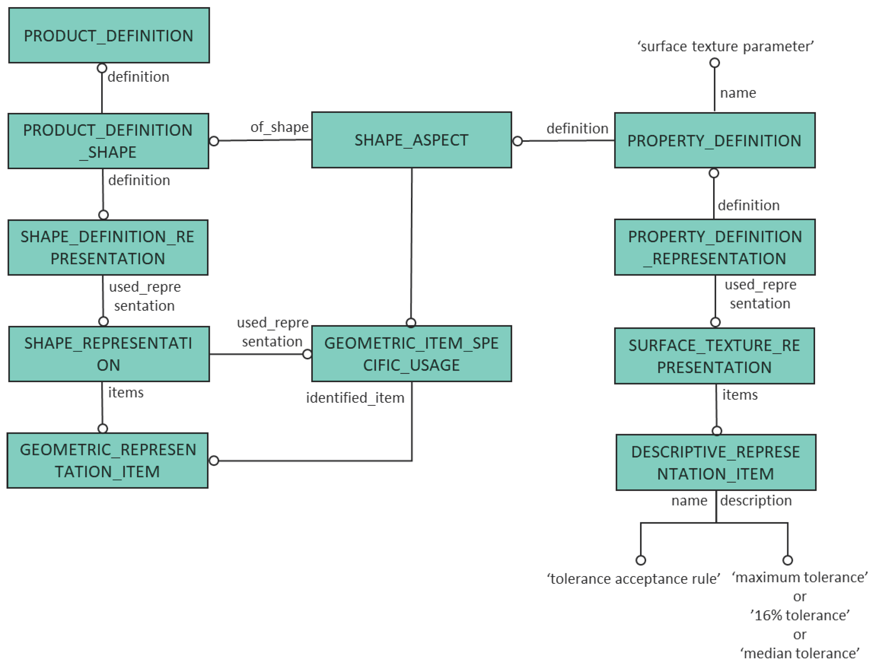
These entities and attributes are mapped to the entities of Integrated Generic Resources: Fundamentals of product description and support (Part: 41) and Material and other engineering properties (Part: 45). The entity ‘STANDARD_SURFACE_TEXTURE_PARAMETER’ maps to ‘PROPERTY_DEFINITION’ entity of Product property definition schema of Part: 41. The entities ‘DESCRIPTIVE_REPRESENTATION_ITEM’ and ‘MEASURE_REPRESENTATION_ITEM’ from Qualified measure schema of Part: 45 can be used to add the values to the descriptive and physical measurable attributes, respectively. Figure 5 shows the method of adding the parameter ‘tolerance acceptance rule’, which cannot be matched directly to any entity or attribute in the standard.

Addition of Custom Annotation String Using Standard Entities

It was suggested in Section. Section 6.1 that the custom string of surface texture annotation can be added using the entity ‘TEXT_LITERAL.’ The custom annotation string can also be added using the method depicted in Figure 5. The custom string should be added to the ‘description’ attribute of the ‘DESCRIPTIVE_REPRESENTATION_ITEM’ entity and ‘user defined string representation’ should be used for the ‘name.’

7. Adding Other Relevant PMI to STEP Files

7.1. Thread Information

Thread specification is one of the key information items about the joining process during the assembly. Generally, designers do not model the exact geometry of the thread features. The thread is specified using ‘cosmetic thread’, a feature provided by CAD tools. In the manufacturing drawing the threaded region is annotated with a thread note. The same thread annotation can be added to the corresponding geometric element in the STEP file using the method described in Section. Section 6.1. The thread annotation will start with the letter combination ‘THD’ and other four-letter codes will start with ‘TD’. The custom string can be formed to match the needs of metric or unified thread specifications.

7.2. Special Coatings and Paints

The information about the special coatings and paints on part surfaces can be added as specified in the Application Module Surface conditions (Part: 1110). The entity ‘COATING_LAYER’ defines the properties of coatings. This entity is mapped to the entity ‘SHAPE_ASPECT’ from the Integrated Generic Resource: Fundamentals of product description and support (Part: 41).
The coating material can be specified using the entity ‘MATERIAL_IDENTIFICATION’ of the Application Module Generic Material Aspects (Part: 1681) which maps to the entity ‘MATERIAL_DESIGNATION’ of the Integrated Generic Resource: Material and other engineering properties (Part: 45).

7.3. Material

The Application Module Generic Material Aspects (Part: 1681) specifies the information requirements for adding material and material properties like density and maps these requirements to the Integrated Generic Resource: Material and other engineering properties (Part: 45). Using the entity ‘MATERIAL_DESIGNATION’ from Material property definition schema, material can be added to the STEP files at part level as shown in Figure 6.
The material specification here is added at the part level by directly referencing the ‘PRODUCT_DEFINITION’ entity, while the material for coatings (Section 7.2) is defined for the particular surface of the part using ‘SHAPE_ELEMENT’ entity.

Material Properties

Any material property like density, hardness and strength can be added to the STEP files using the other entities defined in the same Integrated Generic Resource: Material and other engineering properties (Part: 45). Figure 7 shows the method of adding the density at the part level.

7.4. Volume and Mass

The measure, product property definition and product property representation schemas from the Integrated Generic Resource: Fundamentals of product description and support (Part: 41) can be used for adding various physical properties to the STEP files. The mass value can be directly added to the part using the standard entities. The entities for adding volume are already defined in the standard. The method described in the CAx Recommended Practices for User Defined Attributes [49] is used to define the units for volume.

7.5. Bounding Box

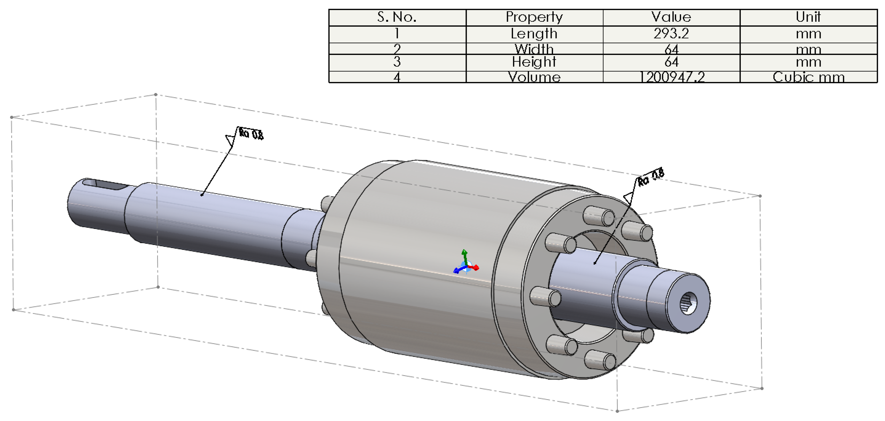
There are no entities defined in STEP AP242 standard to add bounding box dimensions directly to the part. A method is proposed in the CAx Recommended Practices for Geometric and Assembly Validation Properties [50] for adding a bounding box to the STEP file. The use of two ‘CARTESIAN_POINT’ entities was recommended to represent the two corner points of the diagonal of the bounding box. We used the same method to add the bounding box of the rotor as shown in Figure 8.

8. Constraint Identification

As mentioned in Section 2.2, the object properties are one of the key parameters in grasp planning and gripper selection. In the case of industrial applications, the geometry of the objects is precisely defined during the design phase of the product life cycle. This section proposes a method of reusing the part geometry along with the PMI to identify the object parameters that can be used to specify the constraints for grasp planning and gripper selection.

8.1. Identification of Handling Features from STEP Files

Van Holland et al. [51,52] classified the features as ‘handling features’ and ‘connecting features’ and used these features of grasp planning in an assembly process. They further classified the handling features as feeding, fixturing and grasping features. The feeding and fixturing features are used while feeding and initial presentation of components to the feeding area and these features are not available for grasping. This type of classification is not beneficial when the initial feeding and fixturing positions are not defined in the case of bin-picking or where visual sensing is used.
This paper proposes the classification of handling features into the following three categories.
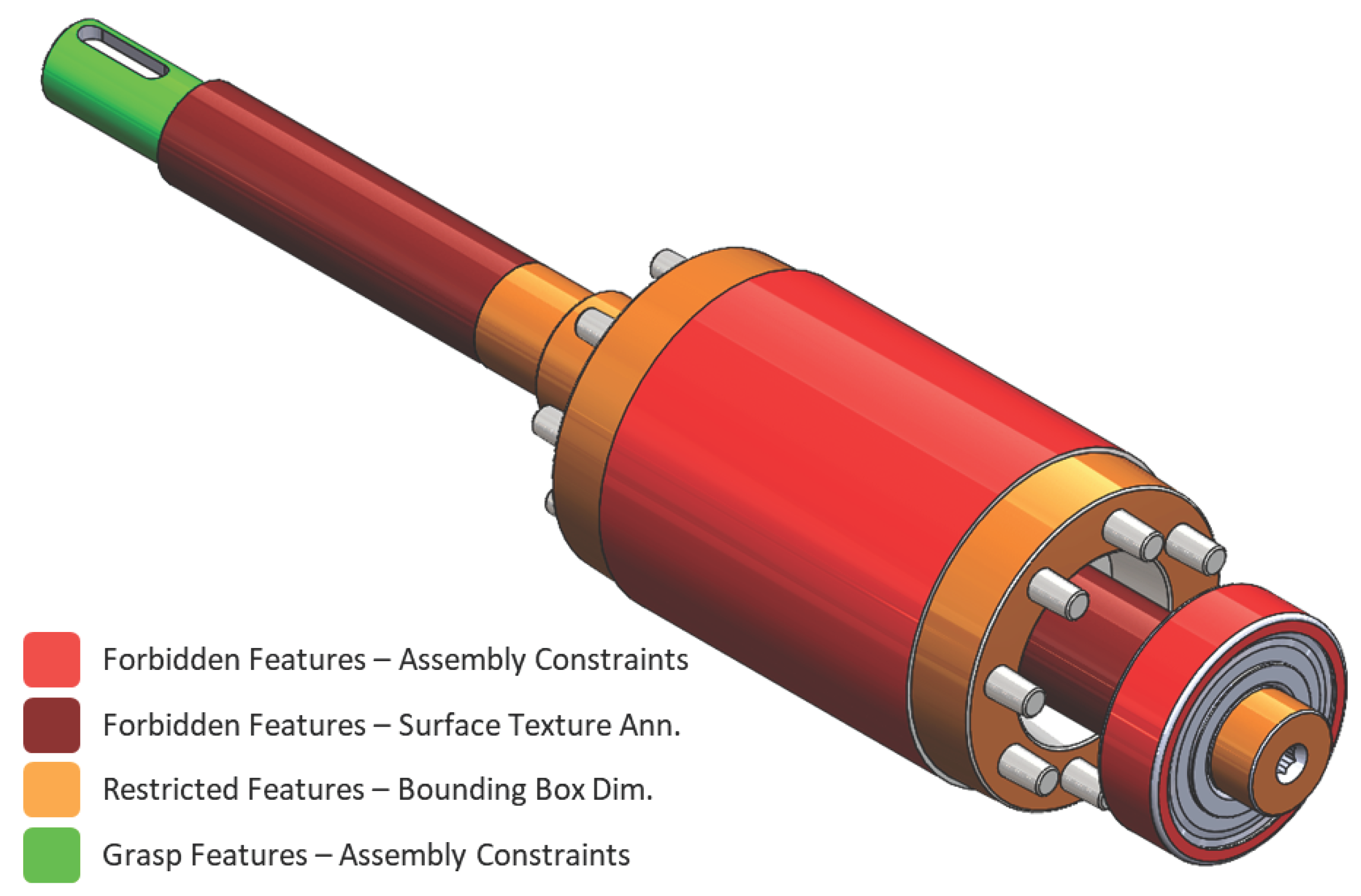
  • Forbidden Features: The features that are strictly not available for grasping are referred to as forbidden features. These include the assembly/mating features and the functional features that might be damaged by the grippers, like threaded regions [21], surfaces with special coatings and surface finish requirements. Only special surface finish specifications on particular features are used to identify forbidden features, not the default surface finish requirement that applies to the entire part.
  • Restricted Features: The features that can be used during the initial stages of handling tasks like re-orienting and moving from the initial position to the start of assembly engagement are considered as restricted features. For example, in the case of a shaft and housing assemblies both the ends of the shaft are available for grasping in the initial stages of handling. As the shaft starts engaging with the housing during the assembly, one end becomes unavailable for grasping depending on the direction of assembly. Here, such an end of the shaft is a restricted feature and can be used during the initial stages of handling and assembly process. Bounding box dimensions are used to derive the restricted features.
  • Grasp Features: The remaining features on the part are open for grasping during all the stages of handling and assembly. These features are called grasp features.
One major criterion in applying the constraints of various part features and gripper selection is that the part should not be damaged during the handling process [12]. The following steps are followed in identifying various handling features from the STEP files.
  • Identify the global coordinate system of the assembly
  • Identify the forbidden features: Features with
    • Assembly constraints
    • Surface texture annotations
    • Thread annotations
    • Coating information
  • Identify the bounding box dimensions of part and mating sub-assembly
  • Convert the bounding box of the part to the global coordinate system
  • Using the mating features, find the final position of the part and its bounding box
  • Find the restricted features, by calculating the interference of the part bounding box with the bounding box of the mating part/sub-assembly
  • The remaining features are identified as grasp features
  • Extract the shape and dimensions of the grasp features
  • Extract/calculate the part properties like density, strength, volume and weight
  • Use these properties for gripper selection, grasp planning and motion planning with collision avoidance
Table 5 shows various types of information from STEP files and which constraint they define.

8.2. Gripper Selection

The object parameters extracted from the STEP AP242 files become input to the selection process of an appropriate gripper for assembling the part. The dimensions of grasp features, part weight and material properties are used to find a gripper. This paper considers only force closure grasp with impactive grippers. A two-level criterion is used in selecting the grippers. The first level narrows down the list of appropriate grippers based on their grasp width and payload. The second level identifies the suitable grippers depending on the maximum gripping force and frictional forces between the gripper and the part. The criterion for selecting the right gripper is as follows.
  • Level 1:
    • The size of the grasp features (width/diameter) should be between the minimum and maximum grasp width of the gripper.
    • When the minimum grasp width of the gripper is not available, the stroke should be greater than the grasp features’ size.
    • The gripper’s payload should be greater than the part weight. This paper suggests a maximum limit to the gripper’s payload to twice the weight of the part.
  • Level 2:
    • The gripping force should be able to lift the part only through friction, i.e., the frictional force ( F f ) should be greater than the gravitational force [1], as shown in Figure 9.
      F g > ( m · g ) / ( μ · n )
      where F g : Gripping force;
      F g = μ · n · F f
      m: mass of the object;
      g: acceleration due to gravity;
      μ : coefficient of friction between the gripper fingers and the object;
      n: number of gripper finger.
Here, the part is considered rigid under the gripping forces. While identifying the grasp regions of the object, the damage to surface finish, threads and coating is already considered and such regions are classified as forbidden regions. Another aspect that can be considered in the selection of the gripper is its weight. If the weight of the gripper is large, it will take a significant portion of the robot’s payload. As we have limited the payload of the gripper to a maximum of twice the object weight, this eliminates the possibility of selecting a big/heavy gripper that can impact the robot’s payload.

8.3. Grasp Planning/Execution

Once the proper gripper is in place and all the object constraints are identified, the next task will be to plan or execute the grasp. For simple geometries where the gripper is close to the desired grasp location, constraint-based robot programming can be used to create a controller with which the gripper position converges to the grasp position. eTaSL/eTC is a constraint-based task specification system based on Lua for robot programming [53]. The gripping constraints can be easily included in the constraint set defined by Mohammed et al. [39] for completing the assembly operation. For simple geometries where the initial conditions place the robot manipulator further from the grasping location, Somani presents a sampling-based motion planner that samples in the nullspace of geometric constraints [24]. For more complicated geometries where the approach trajectory to the grasp location may require multiple reorientations of the gripper to avoid collision with the environment or forbidden surfaces, a more general motion planning solution such as the solvers from OMPL [54] is required. Evaluation of which solution to use is system architecture and workspace layout dependent and not part of the current work.

8.4. Motor Use Case

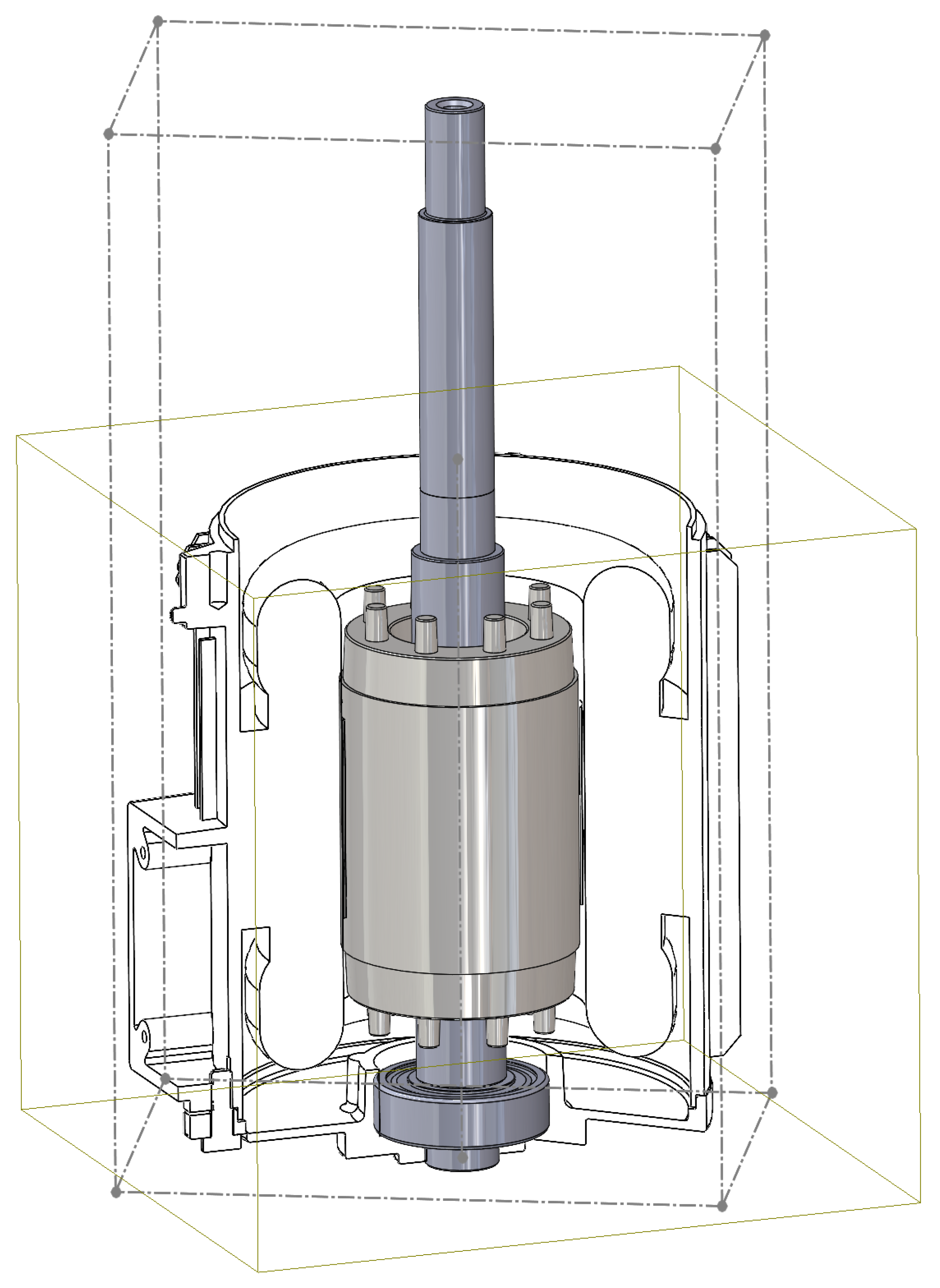
This process is applied to a motor assembly. Figure 8 shows the rotor with the bounding box, volume and surface texture annotations along the part coordinate system and center of mass (coinciding with the origin of the part coordinate system). The PMI in this paper does not correspond to the actual design of the part, but hypothetical PMI was added to demonstrate the method. The PMI is added to the housing and rotor parts using JSDAI API [55]. Figure 10 shows the rotor assembled with the motor housing.
The relevant information is identified and extracted from the STEP files and used in identifying the various types of features on the rotor part.
Figure 11 shows the various types of handling features of the rotor sub-assembly. Only the grasp feature (shown in green) is grasped from starting of handling until the completion of the assembly task. The restricted features can be used for extra support during movement and collision avoidance of the part from the initial position. The forbidden features are identified from the assembly constraints and surface texture annotations. All other PMI such as material is also extracted and used to select the appropriate gripper for the assembly operation.
The diameter of the grasp feature is 15.97 mm and the weight of the rotor sub-assembly is 2.88 kg. With these values, the criterion described in Section 8.2 is followed to select a suitable gripper for this assembly operation. A total of 24 two-fingered impactive grippers from four different manufacturers are considered. The summary of these grippers is given in Table 6.
Taking a coefficient of friction of 0.25 for steel–steel contact between the gripper fingers and the part, the minimum gripping force needed is 56.51 N. With these values of weight, diameter and gripping forces, five grippers that match the criterion were selected. This demonstrates that suitable grippers can be selected by using the object parameters and constraints extracted from the STEP AP242 files.

9. Conclusions

This paper demonstrated how the relevant product geometric and manufacturing information from STEP AP242 files could be reused in grasp planning and gripper selection. Two ways of adding the surface texture annotation to the STEP files are described. Using these methods, the surface finish annotations are semantically added to the STEP files as per the latest ISO standards on surface texture annotations. Though the STEP AP242 standard is defined to include surface texture information as per ISO 1302:2002, the methods presented in this paper enable the addition of surface texture annotations as per the latest ISO 21920-1:2021 standard. These methods can also be easily adapted to add areal surface texture symbols as per the ISO 25178-1:2016 standard. Other relevant information is added to the STEP files as per the latest STEP AP242 standard that match the recommendations of the CAx implementer forum.
This paper proposes a novel classification of handling features and a method to identify them using the product information from the STEP files. This classification is appropriate for handling and assembly operations and can also be combined with other data-driven or sensor-dependent grasp planning strategies. The rules are used to identify various types of handling features on a rotor of a motor assembly, as demonstrated in the use case. A criterion for selecting the grippers using the object parameters extracted from the STEP AP242 files is presented. This is also demonstrated by selecting appropriate grippers for handling the rotor sub-assembly.
The surface texture annotations are only used in identifying the constrained regions of forbidden features in this paper. However, these annotations are fully semantic and can be used for other manufacturing and downstream processes of surface roughness inspection and quality assurance. The restricted features can be used in supporting and handling large objects using multi-robotic systems during the initial phases or until when those features actually start engaging with the other parts.

Author Contributions

Conceptualization, S.K.M., M.H.A. and L.T.; methodology, S.K.M.; writing—original draft preparation, S.K.M.; writing—review and editing, S.K.M., L.T. and M.H.A.; supervision, L.T.; All authors have read and agreed to the published version of the manuscript.

Funding

The work reported in this paper is supported by the Norwegian Research Council infrastructure project MANULAB: Norwegian Manufacturing Research Laboratory under grant 269898. And partially based on activities within the center for research-based innovation SFI Manufacturing and partially funded by the Research Council of Norway under contract number 237900.

Data Availability Statement

Not applicable.

Acknowledgments

The authors would like to thank Mjøs Metallvare for providing the CAD model for the use-case example.

Conflicts of Interest

The authors declare no conflict of interest.

Abbreviations

The following abbreviations are used in this manuscript:
ASMEAmerican Society of Mechanical Engineers
CADComputer Aided Design
CAEComputer Aided Engineering
DTDigital Thread
GD&TGeometric Dimensioning and Tolerancing
ISOInternational Standards Organisation
MBDModel Based Definition
MBEModel Based Enterprise
NCNumerical Controlled
OEMOriginal Equipment Manufacturer
PMIProduct Manufacturing Information
SMESmall and Medium Enterprise
STEPSTandard for the Exchange of Product Model Data

References

  1. Monkman, G.J.; Hesse, S.; Steinmann, R.; Schunk, H. Robot Grippers; WILEY-VCH Verlag GmbH & Co. KGaA: Weinheim, Germany, 2007. [Google Scholar]
  2. Wolf, A.; Steinmann, R.; Schunk, H. Grippers in Motion: The Fascination of Automated Handling Tasks; Springer: Berlin/Heidelberg, Germany, 2005. [Google Scholar]
  3. Lundstrom, G. Industrial Robot Grippers. Ind. Robot. 1973, 1, 72–82. [Google Scholar] [CrossRef]
  4. Dzedzickis, A.; Subaciute-Zemaitiene, J.; Sutinys, E.; Samukaite-Bubniene, U.; Bucinskas, V. Advanced Applications of Industrial Robotics: New Trends and Possibilities. Appl. Sci. 2022, 12, 135. [Google Scholar] [CrossRef]
  5. Lotter, B. Manufacturing Assembly Handbook; VDI-Verlag GmbH: Düsseldorf, Germany, 1986. [Google Scholar]
  6. Boothroyd, G.; Dewhurst, P.; Knight, W.A. Product Design for Manufacture and Assembly; CRC Press: Boca Raton, FL, USA, 2011. [Google Scholar]
  7. Mohammed, S.K.; Arbo, M.H.; Tingelstad, L. Constraint Identification from STEP AP242 files for Automated Robotic Welding. In Proceedings of the 2021 IEEE 12th International Conference on Mechanical and Intelligent Manufacturing Technologies (ICMIMT), Cape Town, South Africa, 13–15 May 2021; pp. 277–282. [Google Scholar]
  8. Bohg, J.; Morales, A.; Asfour, T.; Kragic, D. Data-Driven Grasp Synthesis—A Survey. IEEE Trans. Robot. 2014, 30, 289–309. [Google Scholar] [CrossRef] [Green Version]
  9. Honarpardaz, M.; Tarkian, M.; Olvander, J.; Feng, X. Finger design automation for industrial robot grippers: A review. Robot. Auton. Syst. 2017, 87, 104–119. [Google Scholar] [CrossRef] [Green Version]
  10. De Souza, J.P.C.; Rocha, L.F.; Oliveira, P.M.; Moreira, A.P.; Boaventura-Cunha, J. Robotic Grasping: From Wrench Space Heuristics to Deep Learning Policies. Robot. Comput.-Integr. Manuf. 2021, 71, 102176. [Google Scholar] [CrossRef]
  11. Kleeberger, K.; Bormann, R.; Kraus, W.; Huber, M.F. A Survey on Learning-Based Robotic Grasping. Curr. Robot. Rep. 2020, 1, 239–249. [Google Scholar] [CrossRef]
  12. Owen, A.E. Flexible Assembly Systems; Springer Science + Business Media: New York, NY, USA, 1984. [Google Scholar]
  13. Cuadrado, J.; Naya, M.A.; Ceccarelli, M.; Carbone, G. An optimum design procedure for two-finger grippers: A case of study. IFToMM Electron. J. Comput. Kinemat. 2002, 15403, 2002. [Google Scholar]
  14. Fantoni, G.; Capiferri, S.; Tilli, J. Method for supporting the selection of robot grippers. Procedia CIRP 2014, 21, 330–335. [Google Scholar] [CrossRef]
  15. Birglen, L.; Schlicht, T. A statistical review of industrial robotic grippers. Robot. Comput.-Integr. Manuf. 2018, 49, 88–97. [Google Scholar] [CrossRef]
  16. Nguyen, V.D. Constructing Force-Closure Grasps. In Proceedings of the 1986 IEEE International Conference on Robotics and Automation, San Francisco, CA, USA, 7–10 April 1986; pp. 1368–1373. [Google Scholar]
  17. Reuleaux, F. Kinematics of Machinery; (First Published in Germany, 1875); Macmillan and Co.: London, UK, 1876. [Google Scholar]
  18. Bicchi, A. On the Closure Properties of Robotic Grasping. Int. J. Robot. Res. 1995, 14, 319–334. [Google Scholar] [CrossRef]
  19. Kleeberger, K.; Schnitzler, J.; Khalid, M.U.; Bormann, R.; Kraus, W.; Huber, M.F. Precise Object Placement with Pose Distance Estimations for Different Objects and Grippers. In Proceedings of the 2021 IEEE/RSJ International Conference on Intelligent Robots and Systems (IROS), Prague, Czech Republic, 27 September 2021–1 October 2021; pp. 4639–4646. [Google Scholar]
  20. Shimoga, K.B. Robot Grasp Synthesis Algorithms: A Survey. Int. J. Robot. Res. 1996, 15, 230–266. [Google Scholar] [CrossRef]
  21. Van Bruggen, M.; Baartman, J.P.; Bronsvoort, W.F. Grips on Parts. In Proceedings of the Proceedings IEEE International Conference on Robotics and Automation, Atlanta, GA, USA, 2–6 May 1993; Volume 2, pp. 828–833. [Google Scholar]
  22. Miller, A.T.; Knoop, S.; Christensen, H.I.; Allen, P.K. Automatic Grasp Planning Using Shape Primitives. In Proceedings of the 2003 IEEE International Conference on Robotics and Automation, Taipei, Taiwan, 14–19 September 2003; Volume 2, pp. 1824–1829. [Google Scholar]
  23. Schmalz, J.; Giering, L.; Holzle, M.; Huber, N.; Reinhart, G. Method for the Automated Dimensioning of Gripper Systems. Procedia CIRP 2016, 44, 239–244. [Google Scholar] [CrossRef] [Green Version]
  24. Somani, N. Constraint-Based Approaches for Robotic Systems: From Computer Vision to Real-Time Robot Control. Ph.D. Thesis, Technical University, Munich, Germany, 2018. [Google Scholar]
  25. Lanni, C.; Ceccarelli, M. An Optimization Problem Algorithm for Kinematic Design of Mechanisms for Two-Finger Grippers. Open Mech. Eng. J. 2009, 3, 49–62. [Google Scholar] [CrossRef]
  26. Department of Defense, United States of America (USA). MIL-STD-31000A: Technical Data Packages; Federal Standardization Manual, Department of Defense: Picatinny Arsenal, NJ, USA, 2009. [Google Scholar]
  27. Herron, J.B. Re–Use Your CAD: The Model–Based CAD Handbook; Action Engineering LLC: Golden, CO, USA, 2013. [Google Scholar]
  28. Urbas, U.; Vrabic, R.; Vukasinovic, N. Displaying Product Manufacturing Information in Augmented Reality for Inspection. Procedia CIRP 2019, 81, 832–837. [Google Scholar] [CrossRef]
  29. Goher, K.; Shehab, E.; Al-Ashaab, A. Model-Based Definition and Enterprise: State-of-the-art and future trends. Proc. Inst. Mech. Eng. Part B J. Eng. Manuf. 2020, 235, 2288–2299. [Google Scholar] [CrossRef]
  30. ISO 10303–242:2014; Industrial Automation Systems and Integration—Product Data Representation and Exchange—Part 242: Application Protocol: Managed Model-Based 3D Engineering. International Organization for Standardization: Geneva, Switzerland, 2014.
  31. Kramer, T.; Xu, X. STEP in a Nutshell. In Advanced Design and Manufacturing Based on STEP; Xu, X., Lee, A.Y.C., Eds.; Springer Series in Advanced Manufacturing: Advanced Design and Manufacturing Based on STEP; Springer: London, UK, 2009; Chapter 1; pp. 1–22. [Google Scholar]
  32. STEP AP242 Project Committee. Development of STEP AP 242 ed2: “Managed Model Based 3D Engineering. Whitepaper. STEP AP242 Project Committee: 2014. Available online: http://www.ap242.org/edition-2 (accessed on 27 November 2022).
  33. ISO 10303–242:2020; Industrial Automation Systems and Integration—Product Data Representation and Exchange—Part 242: Application Protocol: Managed Model-Based 3D Engineering. International Organization for Standardization: Geneva, Switzerland, 2020.
  34. Praveen, O.V.S.; Dileep, B.; Gayatri, S.; Lawrence, D.; Manu, R. Automated Tolerance Analysis of Mechanical Assembly Using STEP AP242 Managed Model-Based 3D Engineering. In Industry 4.0 and Advanced Manufacturing; Lecture Notes in Mechanical Engineering; Springer: Gateway East, Singapore, 2021; pp. 149–157. [Google Scholar]
  35. Feeney, A.B.; Frechette, S.P.; Srinivasan, V. A Portrait of an ISO STEP Tolerancing Standard as an Enabler of Smart Manufacturing Systems. ASME J. Comput. Inf. Sci. Eng. 2015, 15, 021001. [Google Scholar] [CrossRef]
  36. Zhong, R.Y.; Xu, X.; Klotz, E.; Newman, S.T. Intelligent Manufacturing in the Context of Industry 4.0: A Review. Engineering 2017, 3, 616–630. [Google Scholar] [CrossRef]
  37. Thomas, R.G.; Lawrence, D.; Manu, R. STEP AP242 Managed Model–based 3D Engineering: An Application Towards the Automation of Fixture Planning. Int. J. Autom. Comput. 2021, 18, 731–746. [Google Scholar] [CrossRef]
  38. ASME Y14.41:2019; Digital Product Definition Data Practices. The American Society of Mechanical Engineers: New York, NY, USA, 2019.
  39. Mohammed, S.K.; Arbo, M.H.; Tingelstad, L. Leveraging Model Based Definition and STEP AP242 in Task Specification for Robotic Assembly. Procedia CIRP 2021, 97, 92–97. [Google Scholar] [CrossRef]
  40. Mohammed, S.K.; Arbo, M.H.; Tingelstad, L. Using Semantic Geometric Dimensioning and Tolerancing (GD&T) Information from STEP AP242 Neutral Exchange Files for Robotic Applications. Int. J. Interact. Des. Manuf. (IJIDeM) 2022. Submitted for publication. [Google Scholar]
  41. ISO 21920-1:2021; Geometrical Product Specifications (GPS)—Surface Texture: Profile—Part 1: Indication of Surface Texture. International Organization for Standardization: Geneva, Switzerland, 2021.
  42. ISO 1302:2002; Geometrical Product Specifications (GPS)—Indication of Surface Texture in Technical Product Documentation. International Organization for Standardization: Geneva, Switzerland, 2002.
  43. ISO 25178-1:2016; Geometrical Product Specifications (GPS)—Surface Texture: Areal—Part 1: Indication of Surface Texture. International Organization for Standardization: Geneva, Switzerland, 2016.
  44. ISO 21920-2:2021; Geometrical Product Specifications (GPS)—Surface Texture: Profile—Part 2: Terms, Definitions and Surface Texture Parameters. International Organization for Standardization: Geneva, Switzerland, 2021.
  45. ISO 21920-3:2021; Geometrical Product Specifications (GPS)—Surface Texture: Profile—Part 3: Specification Operators. International Organization for Standardization: Geneva, Switzerland, 2021.
  46. ISO 25178-2:2021; Geometrical Product Specifications (GPS)—Surface Texture: Areal —Part 2: Terms, Definitions and Surface Texture Parameters. International Organization for Standardization: Geneva, Switzerland, 2021.
  47. ISO 25178-3:2012; Geometrical Product Specifications (GPS)—Surface Texture: Areal—Part 3: Specification Operators. International Organization for Standardization: Geneva, Switzerland, 2012.
  48. CAx Implementor Forum. PMI Unicode String Specification Examples and Mapping Strategies—for Dimensioning and Tolerancing, GD&T, Surface Texture Symbol and Welding Symbol PMI Annotation Entities. Revision J. 2011. Available online: https://www.mbx-if.org/documents/rec_prac_unicode_strings_rev_j_2011-05-25.pdf (accessed on 27 November 2022).
  49. CAx Implementor Forum. Recommended Practices for User Defined Attributes. Release 1.3. 2014. Available online: https://www.mbx-if.org/documents/rec_prac_user_def_attributes_v13.pdf (accessed on 27 November 2022).
  50. CAx Implementor Forum. Recommended Practices for Geometric and Assembly Validation Properties. Release 4.4. 2016. Available online: https://www.mbx-if.org/documents/rec_prac_gvp_v44.pdf (accessed on 27 November 2022).
  51. Van Holland, W.; Bronsvoort, W.F. Assembly Features in Modeling and Planning. Robot. Comput. Integr. Manuf. 2000, 16, 277–294. [Google Scholar] [CrossRef] [Green Version]
  52. Van Holland, W. Assembly Features in Modeling and Planning. Ph.D. Thesis, Delft University of Technology, Delft, The Netherlands, 1997. [Google Scholar]
  53. Schutter, J.D.; Laet, T.D.; Rutgeerts, J.; Decre, W.; Smits, R.; Aertbelien, E.; Claes, K.; Bruyninckx, H. Constraint-based task specification and estimation for sensor-based robot systems in the presence of geometric uncertainty. Int. J. Robot. Res. 2007, 26, 433–455. [Google Scholar] [CrossRef]
  54. Şucan, I.A.; Moll, M.; Kavraki, L.E. The Open Motion Planning Library. IEEE Robot. Autom. Mag. 2012, 19, 72–82. [Google Scholar] [CrossRef]
  55. LKSoftWare GmbH, Germany. JSDAI. Available online: https://www.jsdai.net/ (accessed on 27 November 2022).
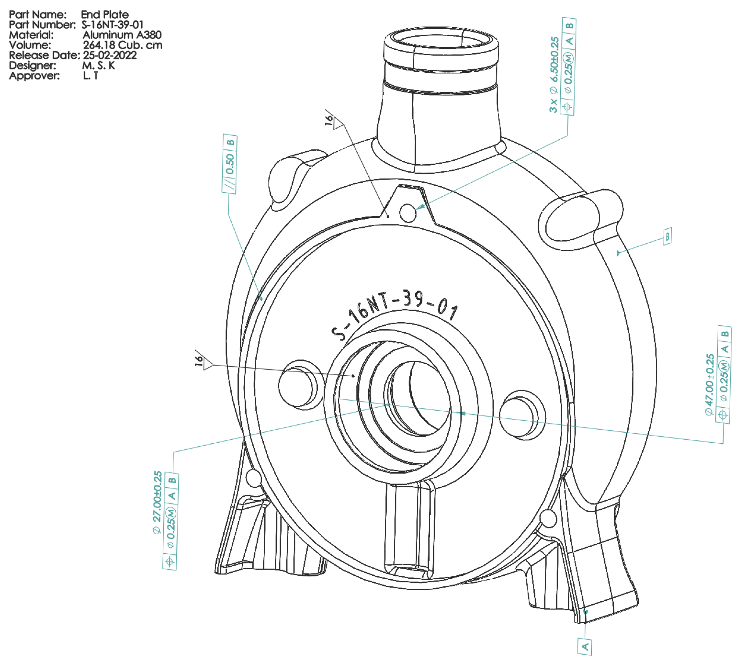
Figure 1. Classification of grasp planning [8,9].
Machines 10 01230 g001
Figure 2. Part with Material, Volume, Surface Texture and GD&T Annotations.
Machines 10 01230 g002
Figure 3. Format of the surface texture symbol with all the possible parameters as per the ISO 21920-1:2021 standard [41].
Machines 10 01230 g003
Figure 4. Surface texture symbol with R-parameter and tolerance limit value and the corresponding annotation string.
Machines 10 01230 g004
Figure 5. Addition of surface texture parameter—tolerance acceptance rule to STEP AP242 file.
Machines 10 01230 g005
Figure 6. Assignment of a material to a part.
Machines 10 01230 g006
Figure 7. Specification of material density directly as a property of the part.
Machines 10 01230 g007
Figure 8. Rotor sub-assembly with the bounding box, volume, surface texture, part coordinate system and center of mass.
Machines 10 01230 g008
Figure 9. Forces acting on the part during gripping.
Machines 10 01230 g009
Figure 10. Rotor sub-assembly assembled with Housing showing bounding boxes.
Machines 10 01230 g010
Figure 11. Handling features of rotor sub-assembly.
Machines 10 01230 g011
Table 1. Various profile and areal surface texture symbols and the corresponding standards [41,42,43].
SymbolTypeNameDescriptionISO Standard
Machines 10 01230 i001ProfileBasic symbolAny manufacturing process permitted1302:2002 (Obsolete)
Machines 10 01230 i002ProfileExpanded symbolMaterial removal required1302:2002 (Obsolete)
Machines 10 01230 i003ProfileExpanded symbolMaterial removal not permitted1302:2002 (Obsolete)
Machines 10 01230 i004ProfileComplete symbolAny manufacturing process permitted1302:2002 (Obsolete)
Machines 10 01230 i005ProfileComplete symbolMaterial removal required1302:2002 (Obsolete)
Machines 10 01230 i006ProfileComplete symbolMaterial removal not permitted1302:2002 (Obsolete)
Machines 10 01230 i007ProfileGraphical symbolAny manufacturing process permitted21920-1:2021
Machines 10 01230 i008ProfileGraphical symbolMaterial removal21920-1:2021
Machines 10 01230 i009ProfileGraphical symbolMaterial removal not permitted21920-1:2021
Machines 10 01230 i010ArealBasic symbolAny manufacturing process permitted25178-1:2016
Machines 10 01230 i011ArealExpanded symbolMaterial removal required25178-1:2016
Machines 10 01230 i012ArealExpanded symbolMaterial removal not permitted25178-1:2016
Machines 10 01230 i013ArealComplete symbolAny manufacturing process permitted25178-1:2016
Machines 10 01230 i014ArealComplete symbolMaterial removal required25178-1:2016
Machines 10 01230 i015ArealComplete symbolMaterial removal not permitted25178-1:2016
Machines 10 01230 i016ArealComplete symbolShowing ‘All Around’ symbol25178-1:2016
Table 2. Surface texture parameters, the positional labels, symbolic representation and their description [41].
SymbolLabelParameterDescriptionCustom Code
TmaxdTolerance acceptance ruleMaximum toleranceSTMX
T16%dTolerance acceptance rule16% toleranceST16
TmeddTolerance acceptance ruleMedian toleranceSTMD
MtSurface layMulti-directionalSMLD
CtSurface layCircularSCRC
RtSurface layRadialSRDL
PtSurface layParticulateSPRT
Machines 10 01230 i017tSurface lay and direction of layParallelSPRL
Machines 10 01230 i018tSurface lay and direction of layPerpendicularSPPD
Machines 10 01230 i019tSurface lay and direction of layCrossedSCRS
Machines 10 01230 i020uProfile directionPerpendicular to the predominant directionSPPD
Machines 10 01230 i021uProfile directionParallel to the predominant directionSPRL
Machines 10 01230 i022uProfile directionCircularSCRC
Machines 10 01230 i023uProfile directionAt an angle to the predominant directionSA<XX>
Table 3. Symbol descriptions and their alphabet identifiers.
DescriptionIdentifier
ProfileP
ArealA
Basic symbolB
Expanded symbolE
Complete symbolC
Graphical symbolG
Any manufacturing process permittedA
Material removal requiredM
Material removal not permittedN
Table 4. Mapping of surface texture symbol parameters to STEP entities and attributes.
Entity.AttributeIndicatorParameter
Standard_surface_texture_parameter.tolerance_typeatolerance type
Standard_surface_texture_parameter.characteristic_typebsymbol for R-parameter/P-parameter/W-parameter
Standard_surface_texture_parameter.characteristic_valuectolerance limit value of the profile surface texture parameter
dtolerance acceptance rule
Standard_surface_texture_parameter.transmission_band_filter_short_waveeprofile S-filter type
fprofile S-filter nesting index
Standard_surface_texture_parameter.transmission_band_filter_long_wavegprofile L-filter type
hprofile L-filter nesting index
Standard_surface_texture_parameter.evaluation_lengthisection length
Standard_surface_texture_parameter.number_of_sampling_lengthsknumber of sections
Standard_surface_texture_parameter.evaluation_lengthmevaluation length
nprofile F-operator association method and element
pprofile F-operator nesting index
qmethod for profile extraction
Standard_surface_texture_parameter.additional_informationrother requirements using OR(n) symbol
Surface_texture.manufacturing_methodsmanufacturing process
Surface_texture.directiontsurface lay and direction of lay
uprofile direction relative to the surface lay
Table 5. Product information from STEP files and its relevance in grasp planning.
Product InformationGrasp Planning Constraints
Assembly constraintsForbidden features
Special surface texture annotationsForbidden features
Thread annotationForbidden features
Special coatingsForbidden features
Bounding box dimensionsRestricted features
Material and material propertiesGripper selection
VolumeGripper selection
MassGripper selection
Feature dimensionsGripper selection
Feature shapeGrasp points and gripper selection
Center of GravitySelection of grasp points
Table 6. Summary of Grippers Considered for the Use Case.
ManufacturerNumber of GrippersPayload Range (Kg)Maximum Grasp WidthStroke
(mm)
Max. Gripping Force (N)
OnRobot52–2043038–160450
Shunk110.55–426205–908460
Robotiq32.5–514050–140235
Festo50.2–4.244020–403716
Publisher’s Note: MDPI stays neutral with regard to jurisdictional claims in published maps and institutional affiliations.