Article

Experimental and Numerical Study of Collision Attitude Auxiliary Protection Strategy for Subway Vehicles

1
Key Laboratory for Track Traffic Safety of Ministry of Education, Central South University, Changsha 410075, China
2
Joint International Research Laboratory of Key Technology for Rail Traffic Safety, Central South University, Changsha 410075, China
3
National & Local Joint Engineering Research Center of Safety Technology for Rail Vehicle, Central South University, Changsha 410075, China
4
CRRC Qingdao Sifang Co., Ltd., Qingdao 266111, China
*
Author to whom correspondence should be addressed.
Machines 2022, 10(12), 1231; https://doi.org/10.3390/machines10121231
Submission received: 31 October 2022 / Revised: 13 December 2022 / Accepted: 13 December 2022 / Published: 16 December 2022
(This article belongs to the Section Vehicle Engineering)

Abstract

:
An auxiliary protection device (rail holding mechanism) was proposed to control the collision attitude of subway vehicles. The dynamics model of head-on collision of subway vehicles was established and verified by the full-scale collision test of the real car; then the force element structure of the rail holding mechanism was equated; finally, the vertical lift and the pitch angle of the three characteristic sections of car body and the wheelsets were used as the evaluation indicators to study the effects of the three design parameters: the gap distance ( x 1 ), the linear stage distance ( Δ   x 2 ) and the stiffness of linear stage ( k 1 ). The results show that the linear stage distance has little influence on the collision attitude of the car body, while the x 1 and k 1 had a greater influence on the collision attitude of the car body. The reasonable reduction of the gap distance x 1 and increase the k 1 can effectively reduce the vertical lift of the wheelsets and alleviate the nodding phenomenon of the train, and reduce the derailment and jumping phenomenon during the train collision.

1. Introduction

Rail vehicle transportation is a green, environmentally friendly, safe, fast, high-capacity form of transportation. Although the rail vehicle’s inherent active safety measures greatly reduce the frequency of accidents and collisions, once a train collision accident occurs, it will bring immeasurable personal injury, property loss, and painful lessons [1,2]. Thus, countries around the world began to conduct extensive research on structural crashworthiness of train design [3,4]. On 4 June 2022, the D2809 passenger train from Guiyang North to Guangzhou South was traveling at the mouth of the Yuezhai Tunnel at Rongjiang Station on the Guiyang–Guangdong Line when it hit a mudslide that had suddenly collapsed into the line, causing the No. 7 and No. 8 cars to derail, killing one driver, and injuring one conductor and seven passengers [5]. Therefore, improving the crashworthiness design of trains, controlling the crash attitude of trains, and reducing the heavy casualties and property damage caused by train collisions have become a popular topic.
Currently, research on crashworthiness has focused on crash energy management [6,7,8], energy-absorbing structures [9,10,11,12], and occupant damage assessment [13,14,15,16,17]. Zhang et al. [18], based on the principle of equal initial collision kinetic energy, proposed the idea of using wheelset translation instead of rotation, from the perspective of the dynamic transmission relationship between the car body, bogie, and wheelset, and investigated the mechanism of the wheelset vertical lift. Zhang et al. [19] build a comprehensive dynamic model to simulate derailment behaviors of the tram under this collision scenario, and presented an investigation into the derailment performance of the tram when an automobile impacts laterally onto the tram flank, and the contribution of several affecting factors to the derailment response were reported. Xu et al. [20] presented an investigation of a newly designed gradual energy-absorbing structure subjected to impact loads using a test trolley for experimental and numerical simulations; this structure is composed of a front-end beam, rear-end plate, outer-side beams, inner-side beams, cross beams, and longitudinal beams. Guan et al. [21] presented an investigation of a cutting aluminum tube absorber for railway vehicles, and the finite element models presented in this study are based on experimental tests. It was shown that the cutting aluminum tube absorber presents a stable deformation mode. Peng et al. [22] proposed a composite energy-absorbing structure for use in subway vehicles, and investigates its collision performance through experiments and numerical simulations. The composite energy-absorbing structure is described in detail, and primarily consists of a front-end plate, square, thin-walled diaphragm, aluminum honeycomb structure, rear-end plate, and guide rail. Xu et al. [23] addressed the energy absorption response and crashworthiness optimization of a gradual energy-absorbing structure, which is composed of nested thin-walled square tubes under axial quasi-static loading. The experimental and numerical results indicated that the deformation model of the structure is regular and stable, and the collapse process is clearly divided into two stages. Although many scholars at home and abroad have conducted extensive research on the crashworthiness of trains, less research has been conducted on increasing the crashworthiness of trains by controlling the train attitude.
At present, the experimental method [23,24,25], finite element method [12,18,26,27,28,29,30], multi-body dynamics method [19,31,32,33,34,35], and equivalent scaling method [6,36,37,38] are mainly used to study the crashworthiness of the energy absorbing structure and the car body derailment gesture of train. Wu et al. [39] designed two kinds of post-derailment devices, and validated, using derailment experiments performed in the laboratory, a half-car derailment test without any post-derailment device. The study was conducted in order to understand dynamic behavior after a derailment. Yang et al. [40] investigated the dynamic mechanical behavior and its effect on energy absorption characteristics of an energy-absorbing device. Three material models were performed on the energy-absorbing device of railway vehicles. Zhang et al. [30] took a the front-end multi-cell energy-absorbing structure of a model high-speed locomotive as the object of study; a numerical simulation of the energy-absorbing structure was carried out to study its crashworthiness, and then the numerical simulation results were verified by an impact test. Based on the basis of the verified numerical simulation, combining the Kriging approximate model and a multi-target particle swarm optimization algorithm, the front energy absorption structure of the high-speed train was optimized, and the reasonable section size parameters were determined. Lu et al. [37] proposed a new method of force/stiffness equivalence-scaled modelling for high-speed trains, which can also be used for the scaled modelling of a prototype composed of thin-walled structures. An initial scaled model of a head car was established by scaling the energy-absorbing part and the undeforming part in a full-scale prototype; numerical simulations indicated that the relationships among deformation, acceleration, and energy absorption are similar in the initial scaled model and prototype. Lai et al. [41] explored the dynamic derailment behaviour caused by rail joint failures before the railway switch panel, to understand the effects of crucial parameters on operating safety. Xu et al.’s study [42] was established based on a coupled finite element method and multi-body dynamics, and was applied to study the derailment behavior of a railway wheelset in both the facing and trailing directions in a railway turnout; the influence of the wheel–rail attack angle and the friction coefficient on the dynamic derailment behavior was investigated through the proposed model. Ren [43] designed an improvement solution for poor train crash stability by adding an anti-climbing and anti-deflection energy-absorbing device to the upper part of the car end, which has the effect of suppressing the nodding motion and lateral response of the train, reducing the risk of train derailment and climbing. Yang et al. [44] established a nonlinear wheel-rail contact model coupled with a vehicle model and a moving track model; they obtained the influence law of vehicle parameters on train collision climbing behavior by simulating a low-speed frontal collision of two identical trains, and analyzed the sensitivity and relative sensitivity of wheel lift to collision speed, body center-of-mass height and second-system vertical stiffness using wheel lift as vehicle collision climbing index; the results showed that train collision climbing is most sensitive to collision speed, more sensitive to body center-of-mass height, and negatively sensitive to second-system vertical stiffness. Lv et al. [45] established a fine finite element model of a fully automatic hook mitigation device and a semi-permanent hook mitigation device, which studied the effects of collision speed, vertical height difference and lateral offset on the action process and motion attitude of the hook mitigation device under different working conditions.
In this paper, the multi-body dynamics model of the head-on collision of a subway vehicle was developed and verified by full scale size experiments. Then, based on the validated dynamics model, an auxiliary protection device (rail holding mechanism) installed on the bottom of the car body was proposed, the force element structure was used for equivalence to compare and analyze the change of the collision attitude of the train before and after the installation of the rail holding mechanism. Finally, the three design parameters, the gap distance ( x 1 ), the linear stage distance ( Δ   x 2 ), and the stiffness of linear stage ( k 1 ) of the rail holding mechanism were parametrically analyzed using the control variable method to study its factor analysis on the train collision attitude.
To illustrate the investigation method, this paper was organized as follows into four aspects. Section 2 introduces an auxiliary protection device (rail holding mechanism). Section 3 establishes a multi-body dynamic model of the head-on collision of a subway vehicle which is verified by full scale experiments, and uses the force element structure equivalence to compare and analyze the control effects. Section 4 parametrically studies the design parameter analysis on the train collision attitude. Section 5 shows the conclusion of this paper.

2. Rail Holding Mechanism

2.1. Equivalent Mechanical Characteristic Curve of a Rail Holding Mechanism

In this paper, a rail holding mechanism is proposed, which is installed between the car body and the rail, as per the schematic diagram is shown in Figure 1. During the train collision, the device takes the vertical relative displacement between the train and the rail as the input, and when the train has a huge vertical lifting amount relative to the rail, through its corresponding equivalent force, the car body and wheelset are restrained from a large vertical lifting amount. The operation process of the rail holding mechanism can be divided into three stages: the static stage, the linear action stage and the stop stage. In the static stage, the rail holding mechanism is opened by setting a threshold value. When the relative vertical displacement of the car body and rail is lower than the opening threshold value of the rail holding mechanism, the rail holding mechanism will not work, and the train will run normally. During this process, four lateral constraint points can be guaranteed, and the whole car body maintains a stable number of lateral constraints and always moves along the track. In the linear action stage, when the relative vertical displacement between the car body and the rail exceeds the opening threshold of the force element structure, the rail holding mechanism begins to output the corresponding force according to the given force displacement curve, so as to suppress the vertical motion of the car body and the anti-climbing behavior of the train. In the stop stage, when the relative vertical displacement between the train body and the rail exceeds a certain range, the force element structure will show a larger stop behavior effect. By outputting a larger interaction force, the vertical displacement between the car body and the rail is limited within a relatively reasonable range, thus ensuring the safe operation of the train on the line.
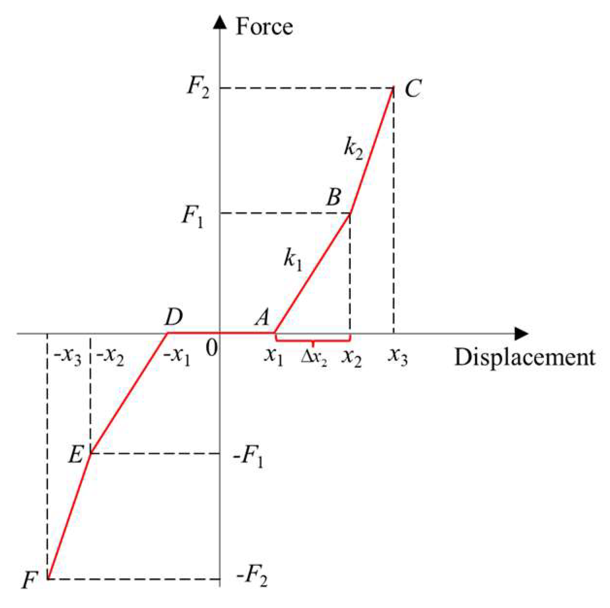
To further analyze the mechanical characteristics of the rail holding mechanism, a force element structure of the dynamic model is used to replace the rail holding mechanism equivalently. The force element structure is realized by a nonlinear mechanical characteristic curve. The mechanical characteristic curve of the force element structure is shown in Figure 2. The parameters of the mechanical characteristic curve of the force element structure mainly include displacement x 1 , x 2 , x 3 and force displacement slope sum of k 1 and k 2 .The calculation method of the output force of the force element structure is shown in Equation (1). When the force element structure is at a static stage, the relative vertical displacement between the car body and the rail is lower, and the rail holding device does not work. At this time, the train maintains a normal running attitude. When the force element structure is in the linear actuation stage, the relative vertical displacement between the car body and the rail is between x 1 and x 2 , and the force element structure is output according to the linear curve from 0 to F1. When the force element structure is in the third stage, the relative vertical displacement between the car body and the rail is between x 2 and x 3 , and the force element structure is output according to the linear curve from F1 to F2. The slope k 1 of the mechanical property curve from 0 to F1 will be smaller than that from F1 to F2. This is because during the stop stage of the force element structure, the rail holding mechanism mainly acts as a stop. At this time, the mechanical curve will show a larger stiffness, resulting in a larger inclination of the curve, thus effectively suppressing the vertical relative displacement of the car body.
F z = k 1 × ( Δ x 2 ) + k 2 × ( x x 2 ) ,   x 2 x x 3 k 1 × ( x x 1 ) ,   x 1 x x 2 0 , x 1 x x 1 k 1 × ( x x 1 ) , x 2 x x 1 k 1 × ( Δ x 2 ) k 2 × ( x x 2 ) , x 3 x x 2
where x 1 is the clearance distance (the opening threshold of the force element structure); x 2 is the linear stage displacement (the opening threshold of the stop behavior of the force element structure); Δ x 2 denotes the distance of the linear stage; x 3 is the corresponding end point of the stop behavior; k 1 and k 2 are the stiffness of linear stage and stop stage, respectively.

2.2. Vertical Evaluation Index

The main function of the force element structure is to inhibit the relative vertical displacement of the train, thus prevent the train from climbing. Therefore, the adoption of a reasonable method to evaluate the vertical collision index of the train during the collision also plays a crucial role in the evaluation of the performance of the force element structure. To evaluate the control effect of the force element structure on the collision attitude of the car body, the main consideration is the vertical displacement of the car body. However, the bogie is directly connected with the car body, and there is mutual coupling between the bogie and the car body. When the bogie has a tremendous vertical displacement, there will be not only the risk of derailment, but also the attitude changes of the car body, causing the phenomenon of train climbing and derailment. Therefore, the vertical displacement of the bogie, especially the wheelset, should also be used as the evaluation index of car body attitude control effect. The evaluation of train attitude control in the existing standard EN15227:2020 [4] is carried out by assessing the maximum lifting of wheelsets.
During the collision, each wheelset of the bogie will jump to varying degrees. Therefore, the displacement distribution vector of the bogie d can be described by the vertical displacement of four wheelsets, as shown in Figure 3. The d can be described by the following equation:
d = [ d 1 , d 2 , d 3 , d 4 ]
where d denotes the displacement distribution vector of the bogie; d 1 , d 2 , d 3 , d 4 denotes the vertical displacement of the four wheelsets.
Relevant research points out that the bogie is at risk of derailment when the vertical lift of a single wheelset of the bogie is too large. Therefore, the evaluation index that comprehensively considers the vertical displacement of four wheels cannot correctly warn the derailment risk of the bogie. Therefore, this paper selects the maximum vertical displacement of four wheelsets as the evaluation index of bogie attitude, and its mathematical expression is shown in the Equation (3).
d m = max { d 1 , d 2 , d 3 , d 4 }
where d m is the maximum vertical displacement of the four wheelsets; d 1 , d 2 , d 3 , d 4 are the vertical displacements of the first wheelset, second wheelset, third wheelset and fourth wheelset, respectively.
For the car body, its structure is large in size and high in freedom of motion. Therefore, this paper describes the collision posture change of the whole body by selecting key nodes on the characteristic sections at different longitudinal positions of the car body, and defining the car body displacement distribution vector with the help of the displacement response of each node. As shown in the Figure 4, the three characteristic sections are as follows: (1) characteristic section S1 at the end of the car body which is 10,880 mm away from the mass center of the car body; (2) characteristic section S2 at the center of mass of the car body; (3) S3 at the end of the car body which is 11,000 mm away from the center of mass of the car body.
In each characteristic section, three key nodes of different vertical heights are selected along the walls on both sides of the car body, based on the lower surface of the body, for a total of six nodes. The displacement changes of the above six nodes are averaged as the displacement changes of the characteristic section. Thus, the characteristic displacement vector Z of the car body is defined, and its mathematical expression is shown in the follow equations:
Z = [ z 1 , z 2 , z 3 ]
z i = 1 6 j = 1 6 t i , j       i = 1 , 2 , 3 ;
where z i represents the average vertical displacement of the i-th characteristic section, ti,j denotes the vertical displacement of the j-th key node on the i-th characteristic section.
Considering that in the process of collision, in addition to vertical translation, there will also be rotational movements such as “head up” and “head nod” phenomenon. For the requirements of car body collision attitude control, it is necessary to comprehensively consider the average vertical displacement of the whole body and the attitude difference at different positions of the car body, so it is necessary to define the displacement field distribution vector of the car body. Its mathematical expression is shown in formula as follows:
θ = 1 2 [ arctan ( z 1 z 2 9800 ) + arctan ( z 2 z 3 11000 ) ]
where θ represents the pitching angle of the car body at the centroid position; z i represents the average vertical displacement of the i-th characteristic section and represents the vertical translational displacement of the car body centroid.
It can be seen from the formula that the car body pitch angle is obtained by numerical average after calculating the average displacement of characteristic sections S1 and S2 and characteristic sections S2 and S3, respectively. When the front displacement of the car body is greater than the rear displacement, that is, when the car body is “head up“, the pitch angle θ is greater than 0; Similarly, when the car body moves “head nod”, the pitch angle θ is less than 0.
To sum up, the sum of the vertical displacement distribution vectors of the car body and the bogie can be used as the evaluation index of the car body attitude. When the vector elements d m , z i and θ are taken as small values, it indicates that the car body attitude control effect is better.

3. Dynamic Simulation and Experiment Result

3.1. Equations of Motion of Subway Vehicles

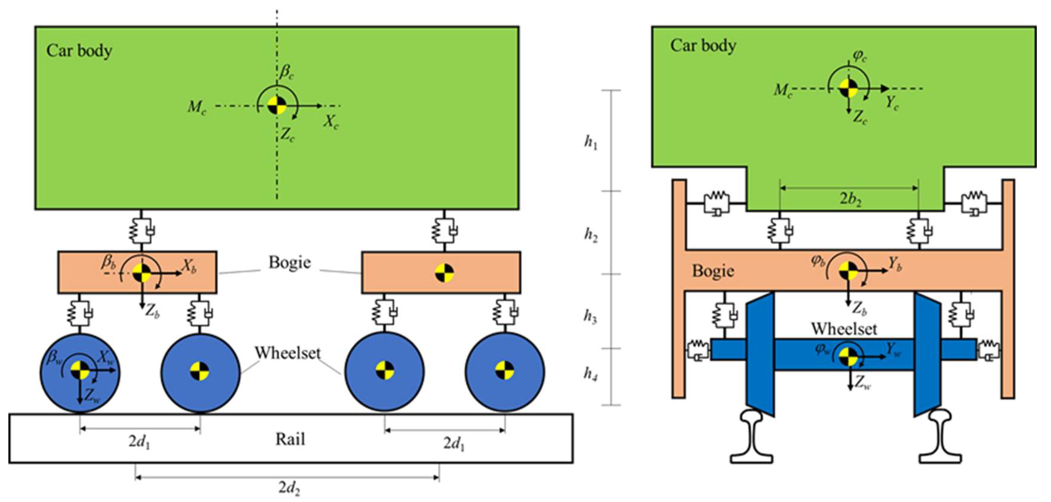
In the process of train collision, there are not only longitudinal impact loads, but also lateral and vertical loads and torques in three directions between the trains, which cause the train to derail, overturn and override phenomenon due to pitching, rolling and yawing. Therefore, when calculating and simulating train collision conditions, it is necessary to consider the longitudinal, vertical and lateral motion movement to build a three-dimensional train dynamic analysis model. According to the vehicle dynamics theory [46], the computational model of the subway vehicle is shown in Figure 5.
In the coupled dynamics model, each vehicle is modeled as a 42-degree-of-freedom (DOF) nonlinear multibody system, which includes seven rigid components: a body, two bogies, and four wheelsets. Each component of the vehicle has six degrees of freedom: longitudinal x, lateral y, vertical z, rolling ϕ , pitching β and yawing ψ . In Figure 1, the x-axis is the direction of travel of the train, the z-axis is the vertical direction, and the y-axis is the lateral direction of the track. From the rail side up, the wheelsets and the bogies rely on a series of springs and dampers, with one linear spring and viscous damping with axial, lateral, and vertical directions on both sides of each wheelset. The axle box springs between each bogie and wheelset have axial, transverse and vertical coefficients of k x 1 , k y 1 and k z 1 ; the axle box suspension damping has axial, transverse and vertical damping coefficients of C x 1 , C y 1 and C z 1 , respectively. The car body and the bogie are connected by the second system of springs and dampers, the bogie left and right sides are axial x, transverse y, vertical z direction of the linear spring and viscous dampers. For each bogie, the second system of axial, transverse, vertical suspension spring coefficients are recorded as k x 2 , k y 2 and k z 2 ; the second system of axial, transverse, vertical suspension damping coefficients are C x 1 , C y 1 and C z 1 . In the Figure 1, b 1 and b 2 are respectively one-half of a system of the suspension span level, two-system suspension span distance; they are respectively one-half of the vehicle wheelbase, fixed distance; train center of mass and two-system suspension height difference, the height difference between the bogie center of mass and the wheelset center of mass and the wheelset center of mass and the height difference between the track surface are recorded as h 1 , h 2 , h 3 and h 4 .
The collision energy absorption characteristics and car body gesture of the whole train are difficult to explore and reproduce through field collision accident experiments. The vehicle-track coupled numerical simulation model is an effective and economical method to analyze the energy absorption management of trains. Using the coordinate system running along the track at the train speed, the equation of motion of the vehicle can be derived according to the Dalembert principle, and a second-order differential equation can be derived. The dynamic equilibrium equation of the n-th vehicle in steady-state motion can be expressed as follows [7]:
M n X ¨ n ( t ) + C n ( x ˙ n ) X ˙ n ( t ) + K n ( x ˙ n ) X n ( t ) = F w r n ( x ˙ n , x n , x ˙ t , x t , v , t ) + F i n k ( x ˙ n , x n , x t )
where M n is the mass matrix of the n-th vehicle, C n and K n are the damping and stiffness matrices, which rely on the real-time condition of the train system to determine the suspension nonlinear properties; X n , X ˙ n and X ¨ n are the displacement, velocity, and acceleration vectors, respectively; x ˙ k , x k , x ˙ t and x t are the displacement and velocity vectors related to the suspension forces and wheel-rail contact forces, respectively; v denotes the train velocity; F w r n represents the vector of the nonlinear wheel-rail contact forces, which is determined by the displacements and velocities of the n-th vehicle and the track. F i n k is the vector of the nonlinear inter-vehicle contact forces due to the couplers and anti-climbers.
The equations of the car body in the longitudinal, lateral, vertical, rolling, pitching, and yawing directions are described as follow [47]:
M c X ¨ c = F x s 1 F x s 2 F x c f F x c b M c Y ¨ c = F y s 1 + F y s 2 F y c f F y c b + M c g ϕ sec + F y c c M c Z ¨ c = F z s 1 F z s 2 F z c f F z cb + M c g + F z cc I c x ϕ ¨ c = M x s 1 M x s 2 + M x c f + M x c b I c y β ¨ c = M y s 1 M y s 2 + M y c f + M y c b + M y c c I c z ψ ¨ c = M z s 1 M z s 2 + M z c f + M z c b + M z c c
where M c is the mass of the car body; X ¨ c , Y ¨ c , Z ¨ c , ϕ ¨ c , β ¨ c and ψ ¨ c are the accelerations of the car body center in the longitudinal direction, lateral direction, vertical direction, rolling directions, pitching directions and yawing directions, respectively. F x s ( i ) , F y s ( i ) , F z s ( i ) , M x s ( i ) , M y s ( i ) and M z s ( i ) denote the mutual forces and the mutual moments between the car body and bogie frame (i = 1,2 represent front bogie frame and rear bogie frame, respectively) in the longitudinal directions, lateral direction, vertical direction, rolling directions, pitching directions and yawing directions, respectively; F x c ( j ) , F y c ( j ) , F z c ( j ) , M x c ( j ) , M y c ( j ) and M z c ( j ) are the inter-vehicle forces and the mutual moments caused by the inter-vehicle connections between the adjacent car bodies (j = f, r represent front car bodies and rear car bodies, respectively) in the longitudinal directions, lateral direction, vertical direction, rolling directions, pitching directions and yawing directions, respectively. F y c c , F z c c , M y c c and M z c c denote the external forces and the mutual moments on the car bodies resulting from the centripetal acceleration when a train is negotiating a curved track; ϕ sec is the angular deflection of the car body rolling caused by the cant of the high rail; g is the gravitational acceleration.
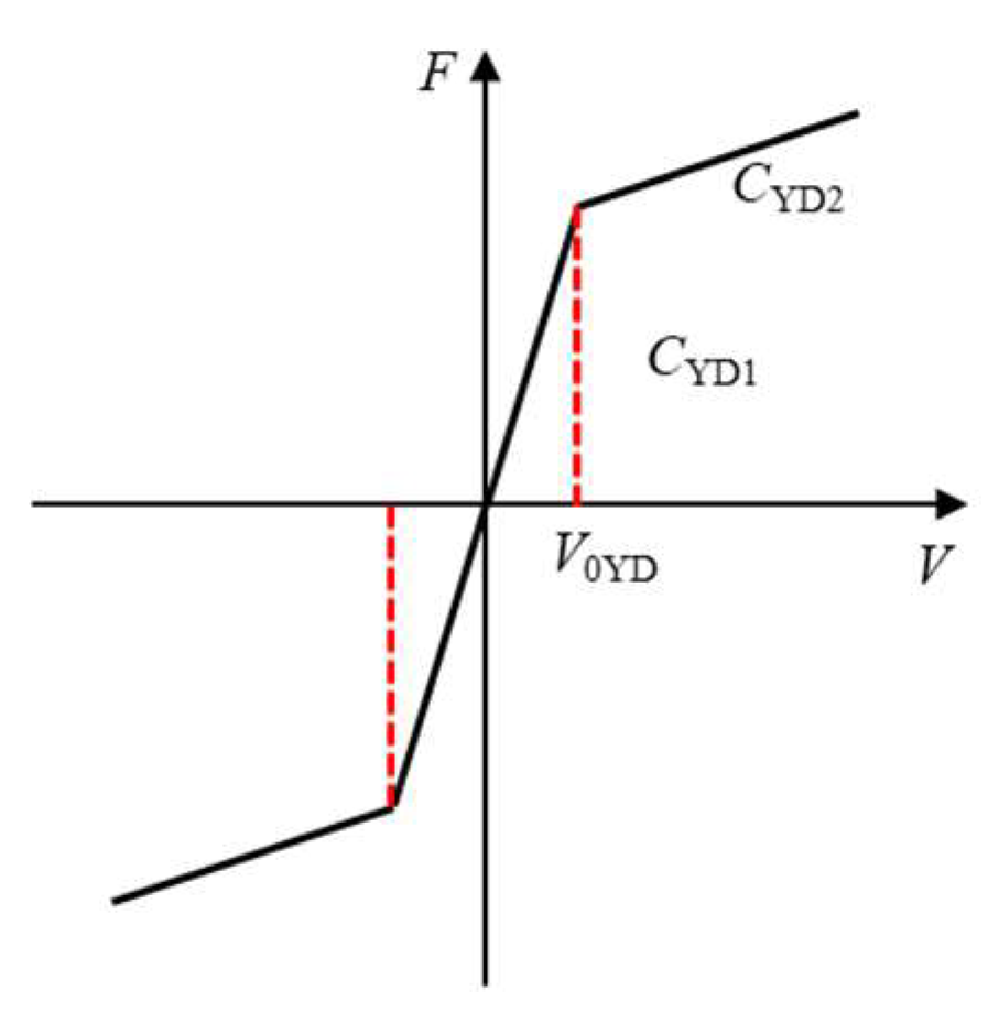
Figure 6 shows the nonlinear behavior of the secondary yaw damper system in the numerical model. Based on the bilinear assumption, the damping contact force related to the velocity for a yaw damper can be express as follow [46]:
F x Y D = C Y D 1 Δ x ˙ Y D , Δ x ˙ Y D < V 0 Y D s i g n ( Δ x ˙ Y D ) C Y D 1 V 0 Y D + C Y D 2 ( Δ x ˙ Y D V 0 Y D ) ] , Δ x ˙ Y D > V 0 Y D
where V 0 Y D is the unload velocity of the yaw damper, C Y D i denotes the equivalent coefficients of the yaw dampers; Δ x ˙ Y D represents the relative velocity along the longitudinal direction between the car body and the tow end points of the yaw damper laterally jointing the bogie frame.
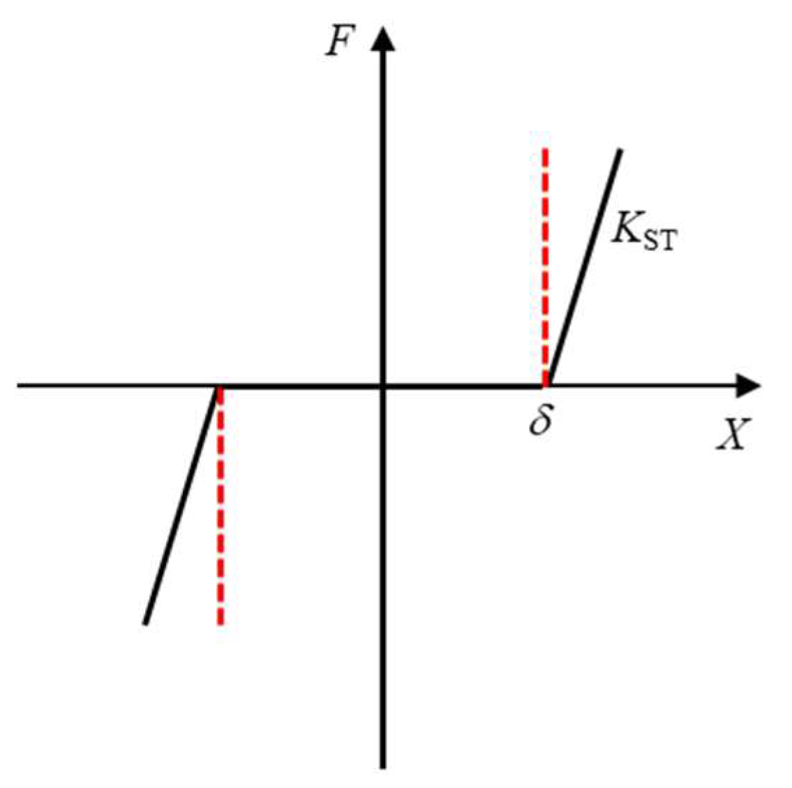
Figure 7 depicts the nonlinear behavior of the bump-stop in the numerical model. The constrain force can be expressed utilizing the relative displacement of the car body and the bump-stop [48].
F S T = 0 , Δ S T < δ s i g n ( K S T ) ,   Δ S T δ
where K S T is the contact stiffness when the car body touch the bump-stop; δ denotes the lateral gap from the car body to the bump-stop; Δ S T represents the relative displacement between the base of the car body and the bump-stop.
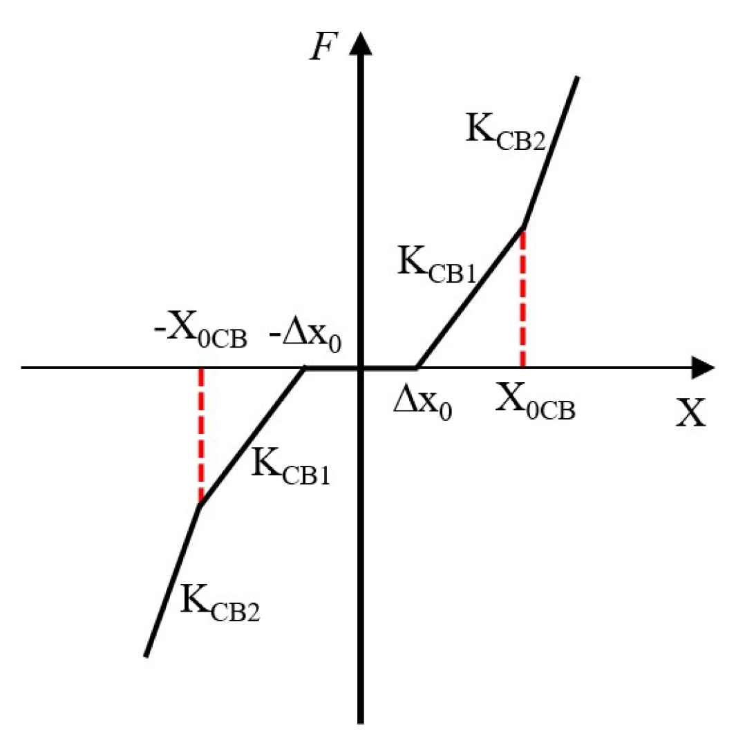
Figure 8 illustrates the nonlinear characteristic of the coupler, which is expressed by the multi-linear spring element in the numerical model. The relationship between the coupler force and the relative displacement between the two end points of the coupler can be described as follow [46]:
F c g = 0 , Δ x < Δ x 0 K C B 1 ( Δ x Δ x 0 ) ,   Δ x 0 < Δ x < X 0 C B K C B 1 ( X 0 C B Δ x 0 ) + K C B 2 ( Δ x 0 X 0 C B ) ,   Δ x > X 0 C B
where Δ x defines the relative shift between the two end points of the couplers connecting the adjacent vehicles in the axial direction; X 0 C B is the initial coupler length; Δ x 0 denotes the coupler slack; K C B i represents the equivalent stiffness coefficient.

3.2. Dynamic Model of Subway Vehicles

Dynamics model of subway vehicles is shown in Figure 9. The dynamics model is modeled by MotionView (Version number: 2021. 1; manufacturer: Altair Engineering, Inc., Michigan, IN, USA) and python secondary development software (Version number: 3.9; manufacturer: Guido van Rossum; Amsterdam, The Netherlands), the model mainly consists of a car body, bogie, wheelset, track, coupler and anti-climbers. The secondary suspension device between the car body and the bogie, the anti-rolling torsion bar between the wheel set and the bogie and the primary suspension are modeled by the bushing unit of MotionView software. The coupler device adopts the nonlinear spring damping model for modeling, and the second development of MotionView is carried out through python, using python sys functions data interface which are provided in MotionView to realize the input of coupler and draft the characteristic curve of coupler device.
In this paper, the coupler and the anti-climbers are used to describe the mechanical characteristics of train collisions, as shown in Figure 10. Figure 10a shows the energy absorption characteristic curves of the coupler and the car body, and Figure 10b shows the energy absorption curve of the anti-climbers. Since the car body is described by a mass point, the deformation energy of the car body is given to the coupler for description. The energy absorption curve of the coupler firstly absorbs energy through the buffer and the collapse tube; when the shear bolt breaks, the coupler is not involved in energy absorption, and the anti-climbers start to absorb energy. Since the anti-climbers of this subway vehicle model extend out of the car body at a short distance, soon after the anti-climbers start to absorb energy, the car body comes into collision contact and starts to absorb energy. The energy absorbed by the car body is reflected by being on the coupler energy absorption curve.
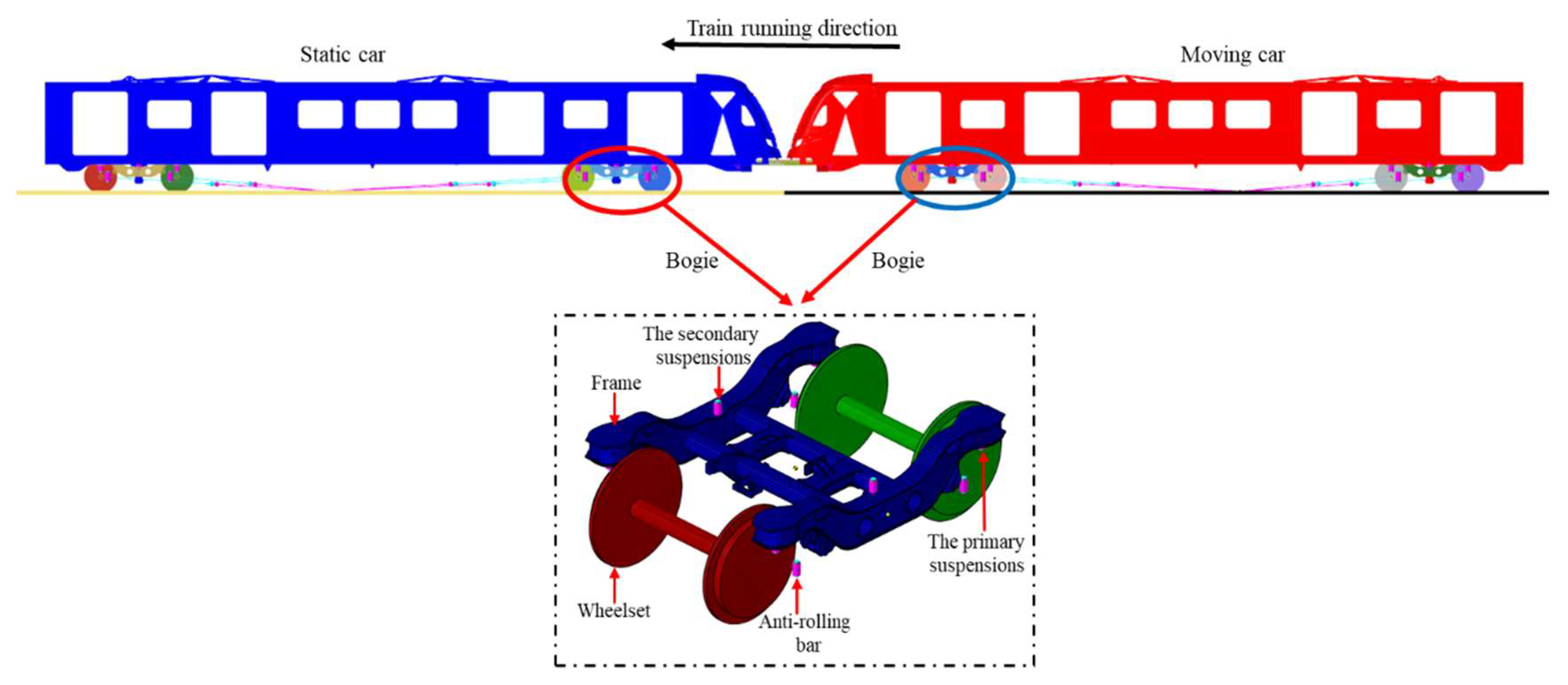
The parameters of subway vehicles refer to a certain subway model, the wheelsets and the bogies are connected by the primary suspensions, while the car body is supported by the bogies through the secondary suspensions. Nonlinear 3D spring–damper elements were used to build the suspension model. The dynamic model of the subway vehicle is shown in Figure 9. The basic parameters of the subway vehicle are shown in the Table 1.

3.3. Crashing Test and Validation

In the research of subway train collisions, carrying out the actual vehicle crash test is the most realistic and effective method to verify the crashworthiness of the train. To verify the feasibility of the established dynamic model, the collision impact test of the head car of the subway vehicle was carried out. The real vehicle test based on the real subway vehicle can truly and completely reflect the energy absorption characteristics of the energy absorption device during the train collision process. The crash test can also obtain the instantaneous attitude of the vehicle, the difference in the attitude of the vehicle before and after the collision, and the changes in physical quantities related to the train attitude during the collision. Figure 11 shows the schematic diagram of the train collision. The crash scenario I of the EN15227:2020 [4] standard was used to perform a collision test on subway vehicles. The test was performed by using a subway vehicle with an overall mass (moving car) to forward collide with another vehicle of the same configuration (stationary car) parked at the front of a rigid wall at a speed of 36 km/h.
The collision of subway lines involves the coupling of several systems. The crash test system of this real car test mainly includes the power system, control system, measurement system, lighting system and high-speed camera system. The line crash test system is shown in the Figure 12.
As shown in the Figure 12, the power system drives the subway to run at the speed of the test settings, The control system mainly includes the control room, which coordinates and controls the operation of other systems to ensure that, during the test, other systems run according to the predetermined test settings. The operation of the measurement system, lighting system and high-speed camera system can complete the testing and acquisition of physical quantities such as force, displacement, speed and acceleration during the dynamic process.
During the test, in order to record the dynamic response related to the train collisions, the key mechanical responses involved in this test were measured, and the specific physical quantities measured, as well as the names, parameters and calibration status of the response measurement equipment used in the test, are shown in Table 2. For the data collection of the measurement equipment of the vehicle during the line collision test, five data acquisition systems of Ki-DAU integrated nxt32 series from Kistler were used. Among them, four units were arranged for the active vehicle and one unit for the passive vehicle. The data acquisition system is fixed in the vehicle’s passenger compartment area in the middle and rear of the stiffness area to prevent the problem of equipment data acquisition failure brought by vehicle impact. Among them, the sampling frequency of the on-board data acquisition instrument is 20 kHz, and the sampling time interval is −0.5 s to 5.0 s; the frame rate of the high-speed camera is 2000 fps/s, and the shooting time interval is −0.5 s to 5.0 s.
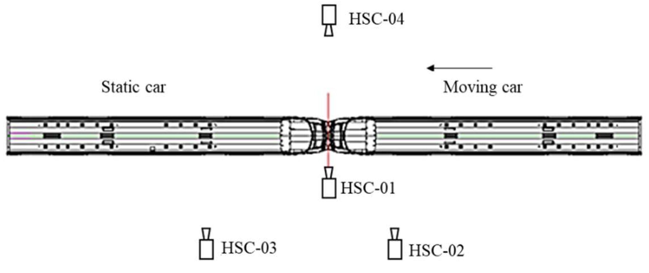
In addition, four high-speed cameras are set to record the deformation sequence during the collision, and the displacement of the train marker point can be obtained through the motion image analysis software. The arrangement of high-speed cameras is shown in Figure 13. Two high-speed cameras, HSC-01 and HSC-04, are placed on both sides of the impact interface to photograph the collision interface; HSC-02 is placed on the side of the moving car to photograph the collision process of the moving car; HSC-03 is placed on the side of the stationary car to photograph the collision process of the stationary car.
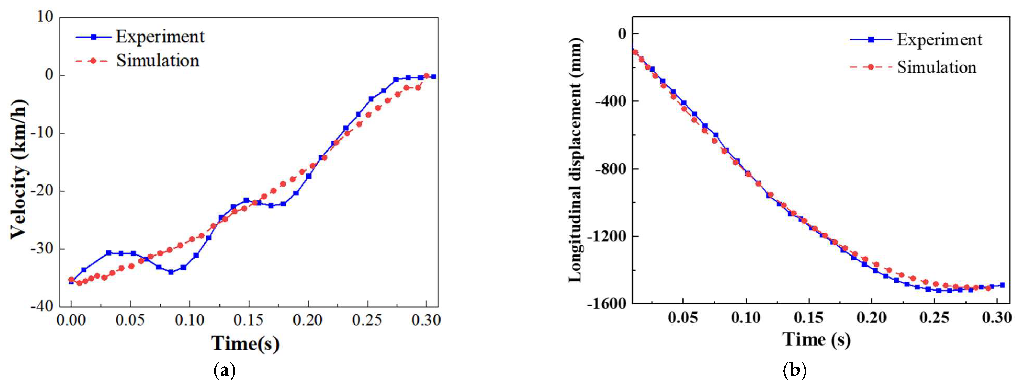
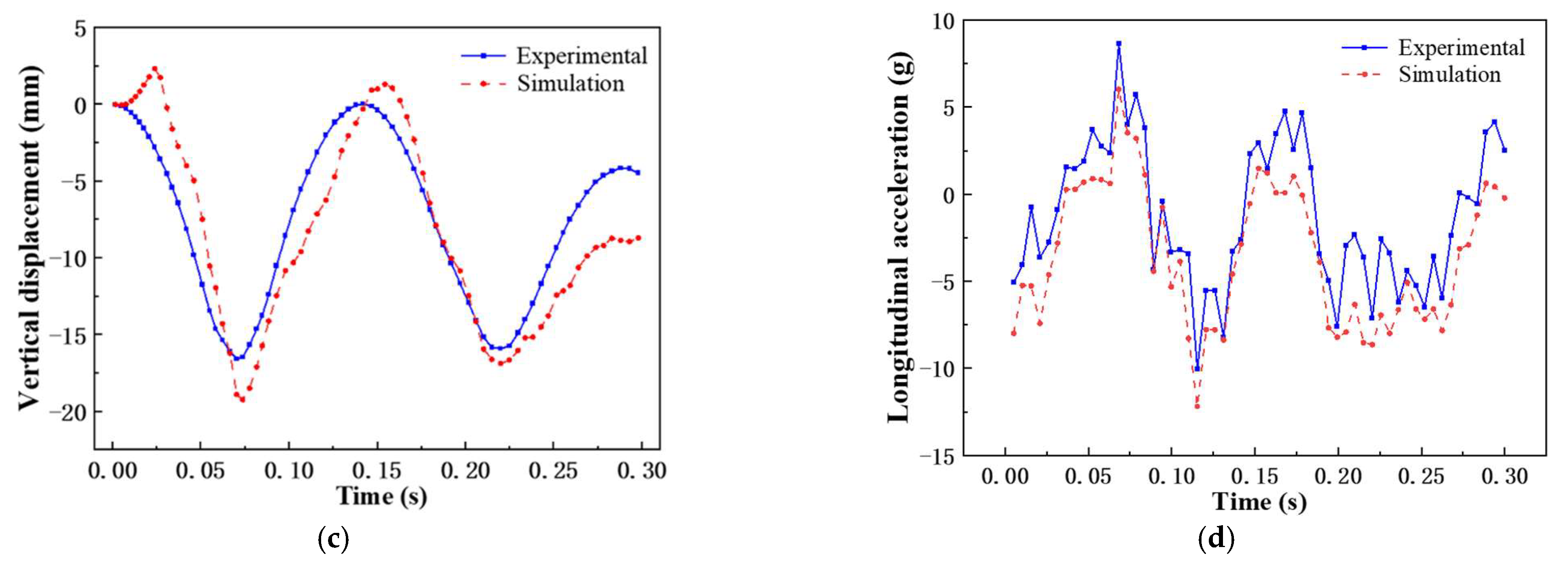
To further verify the accuracy of the dynamics model, the velocity, acceleration and vertical displacement of the car body in the experiment and dynamics simulation are selected as the parameters of the alignment. High-speed photography is used to obtain the velocity, acceleration and vertical displacement of the car body in the experiment. Parameters are selected for output alignment in the dynamic simulation at the corresponding position on the vehicle body, and the comparison of the experiment and dynamics simulation is shown in Figure 14.
Figure 14a shown the comparison between the test results of the longitudinal velocity of the car body and the dynamic simulation results. The results show that the simulation results are in good agreement with the experiment results. When t = 275 ms, the velocity drops to 0, and a certain rebound occurs. The rebound speed of the experiment and simulation are 2.482 km/h and 2.380 km/h, respectively; the error between the simulation and the test is 4.1%. Figure 14b is the comparison between the test results of the longitudinal displacement of the car body and the dynamic simulation results; when t = 0.275 s, the longitudinal displacement of the car body reaches the maximum value of 1502.01 mm and 1496.63 mm, respectively, the error between the two in the maximum displacement time point and displacement size is only 0.35%, and the error does not exceed 5% during the entire collision process; Figure 14c shows the vertical displacement of the vehicle body during the experiment and simulation, the variation trend of the vertical displacement in the experiment and simulation is consistent, and the difference between the peaks and troughs is not large; Figure 14d shows the longitudinal acceleration of the car body during the experiment and simulation, there is a small deviation between the acceleration and the experiment.
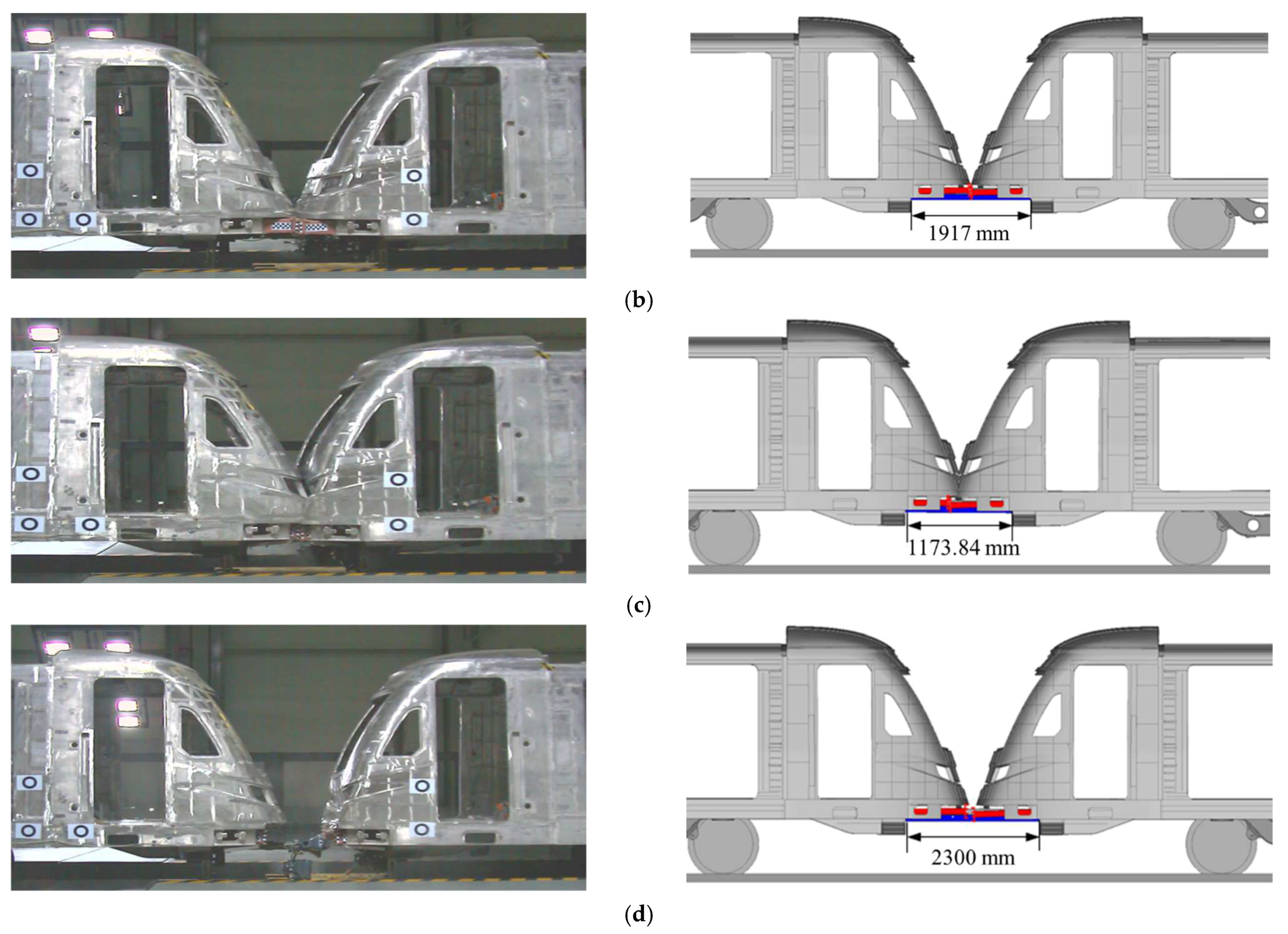
Figure 15 shows the comparison between the collision test and simulation results of the main stages in the collision process. The collision of the head car can be roughly divided into the following stages: anti-climbing energy absorption contact stage, driver’s cab contact stage, energy absorption structure compressed to the maximum, and, finally, the collision ended. By comparing the results of collision test and simulation, the deformation sequence of simulation and experiment is roughly the same, and the time domain of each stage is similar.
In conclusion, the velocity–time curve, longitudinal displacement–time curve, vertical displacement–time curve and longitudinal acceleration–time curve of the car body in the numerical simulation are in good agreement with the impact experiment. It can demonstrate that the simulation model has a good accuracy and can be used for analysis the train collision posture after installation of rail holding mechanism.

3.4. Comparison of Train Collision Posture

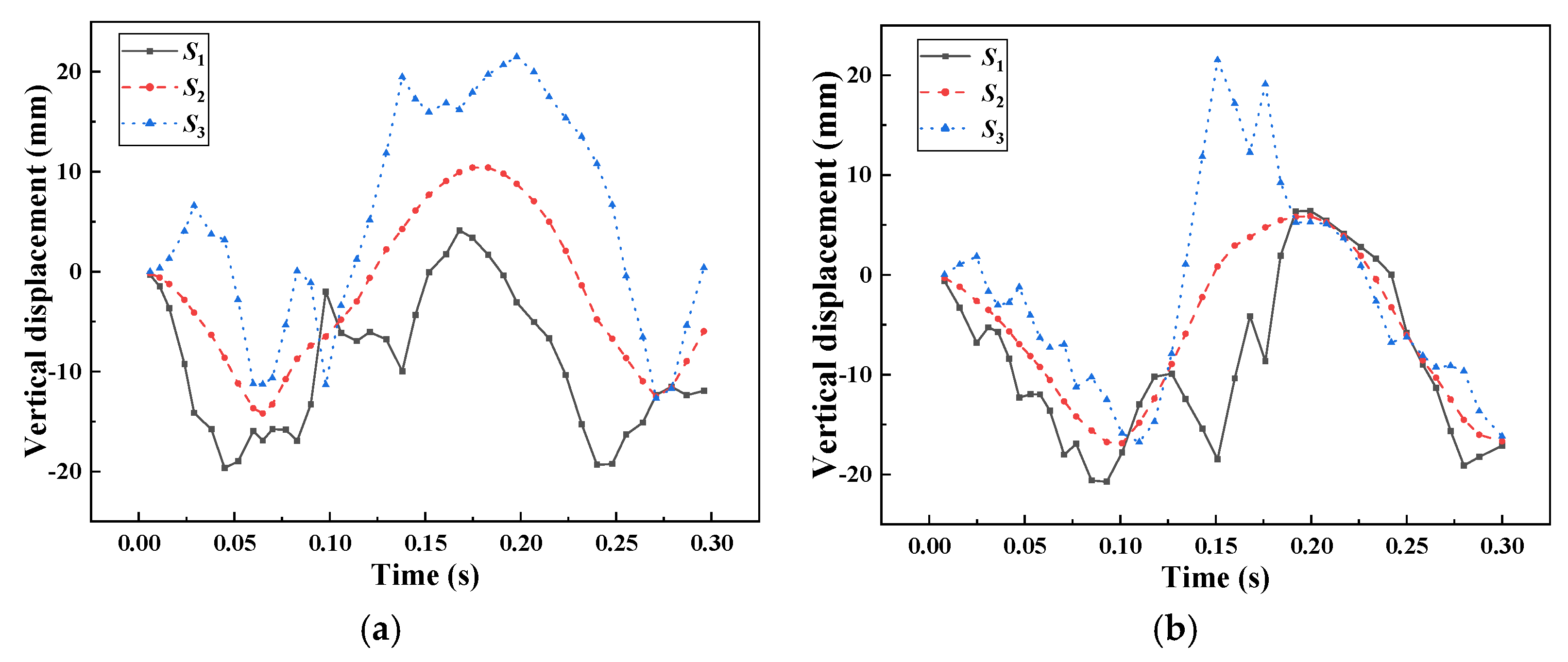
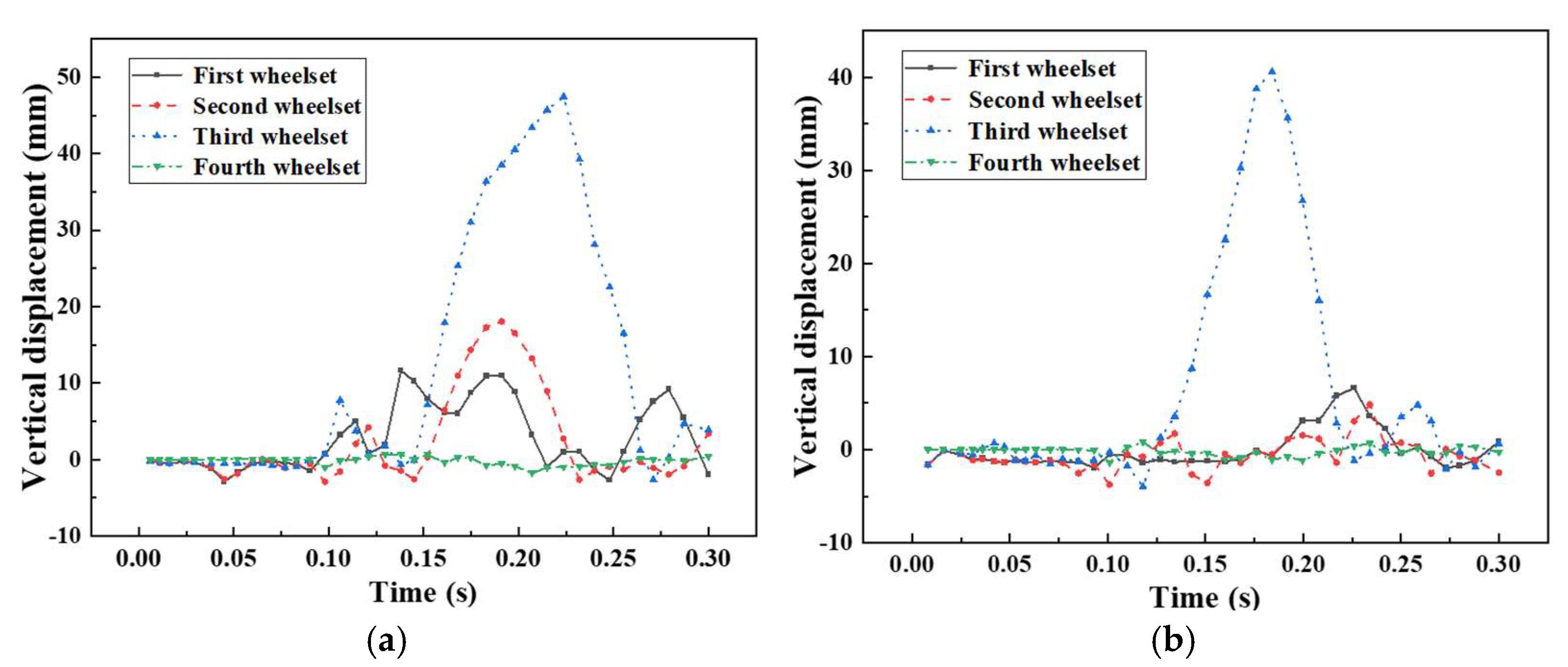
We analyzed the influence of the rail holding mechanism on the collision attitude of the train. Based on the verified train dynamics model, the collision dynamics simulation analysis of the trains without and with the rail holding mechanism were carried out. In the simulation analysis, the moving car crashes into the stationary car stopped on the track at an initial speed of 36 km/h. The characteristic cross section of the car body, the lift of the four wheelset and the pitch angle of the car body are used as evaluation indexes. The comparison results of the characteristic section of the car body in the vertical direction, the vertical lift of the wheelsets and the pitch angle of the car body are displayed in Figure 16, Figure 17 and Figure 18, respectively.
Figure 16a shows the vertical lift of the characteristic section of the train without the rail holding mechanism installed during the collision. Figure 16b exhibits the vertical lift of the characteristic section of the train with the rail holding mechanism installed during the collision. It can be seen from Figure 14 that when the train is installed with the rail holding mechanism, the maximum vertical lift of the characteristic section S2 decreases to less than 5 mm, the maximum vertical lift of the characteristic section S1 is improved, the maximum vertical lift of the characteristic section S3 does not change much, but the speed of decreasing from the maximum vertical lift becomes faster. The overall attitude of the train presents a stable state, and the degree of up and down oscillation of the front section and the rear end of the train, the gesture of the train is smooth, and the up-and-down sway of the front and rear ends of the train is reduced.
Figure 17a demonstrated that the vertical lift of the wheelsets during the collision of the train without the rail holding mechanism; Figure 17b shows the vertical lift of the wheelsets during the collision of the train with the rail holding mechanism. As shown in Figure 17, it can be seen that the maximum vertical lift of the four wheelsets decreases significantly when the train is equipped with rail holding mechanism, among which the maximum lift of the fourth wheelset decreases most obviously, followed by the second wheelset, the third wheelset and the first wheelset. Meanwhile, it can be found that the speed of decreasing from the maximum vertical lift of the four wheelset gets obvious hints, and the vertical lift of the wheelsets is greater than 20 mm. At the same time, it can be found that the speed of decreasing from the maximum vertical lift of the four wheelsets is obviously indicated, and the vertical lift of the wheelsets is more than 20 mm.
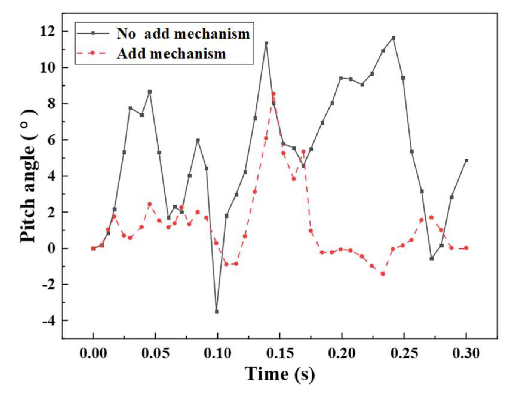
Figure 18 illustrates the comparison of the pitch angle of the train during the collision. As shown in Figure 18, after the installation of the rail holding mechanism, the maximum pitch angle of the train has been reduced and the difference between the maximum pitch angle and the minimum pitch angle has been reduced, which indicates that the nodding phenomenon of the train has been improved and the degree of up-and-down oscillation of the train during the collision has been alleviated.

4. Sensitivity Analysis of the Metro Rail Holding Mechanism

To deeply analyze the influence of the rail holding mechanism of the subway train on the car body posture and wheelset vertical lifting, the standard collision scenario of EN15227:2020 [4] is selected. The moving car collides with the stationary car stopped on the track at an initial speed of 36 km/h, there is a 40 mm height difference between the collision point of the moving car and the stationary car (the stationary car is lower than the moving car). Taking the vertical lifting amount of the three characteristic sections of the car body and the pitching angle of the center of mass of the car body as the evaluation index of the car body posture in the process of train collision, and the vertical lifting amount of the four wheelsets as the evaluation index of the wheelsets, we carried out parametric analysis on the three design parameters x 1 , Δ   x 2 and k 1 of the rail holding mechanism.

4.1. Effect of Rail Holding Mechanism Distance x 1

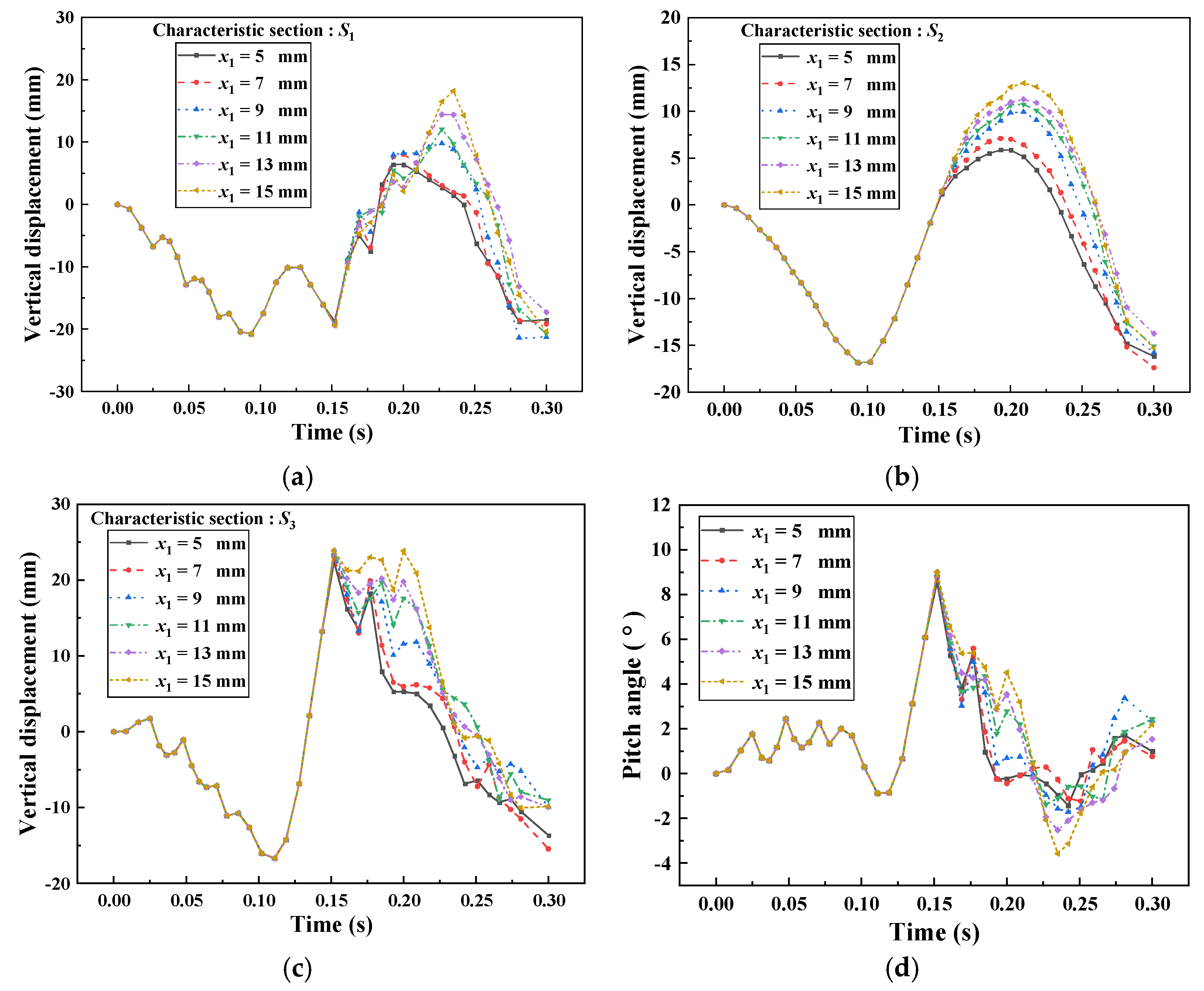
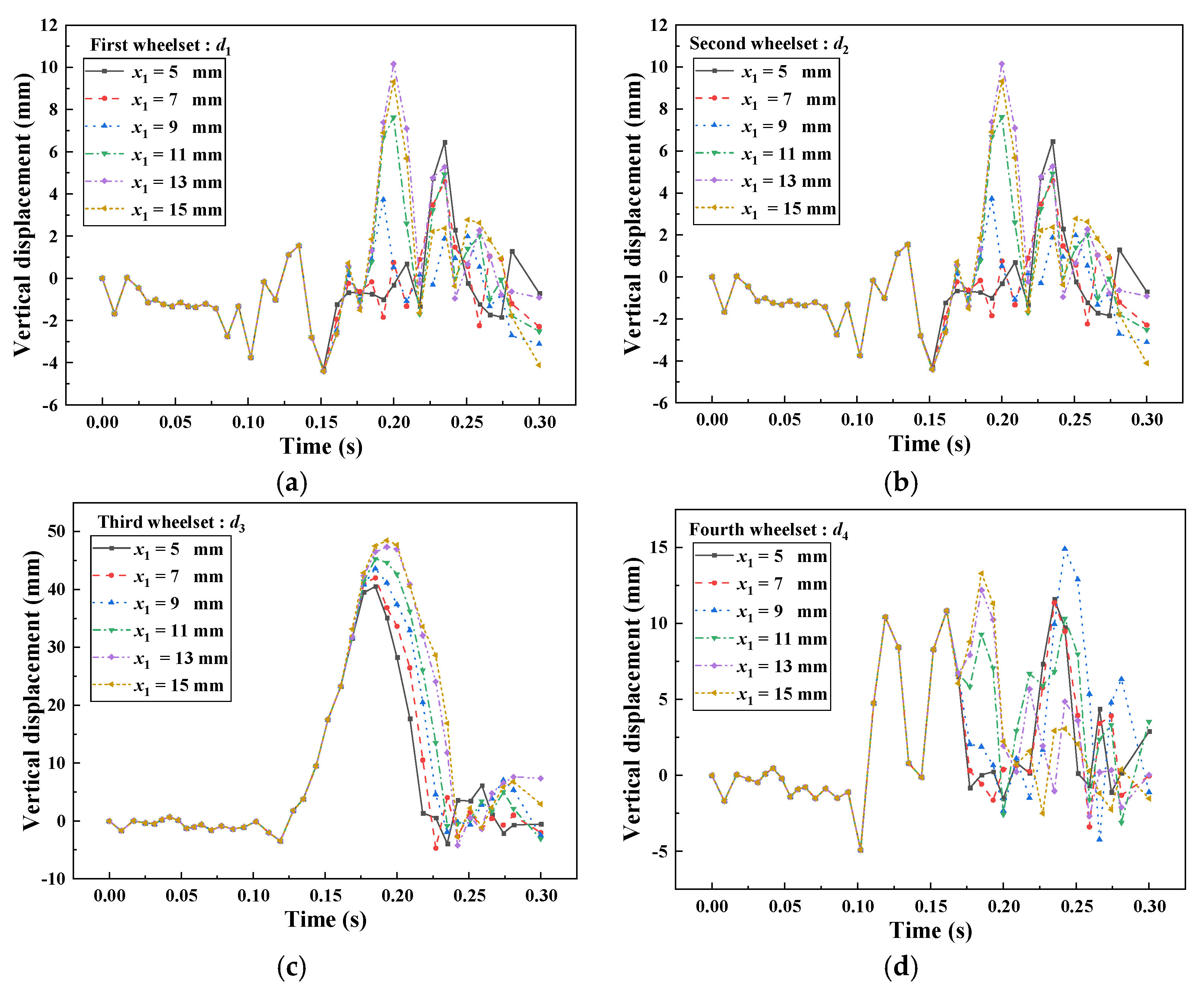
To discuss the effect of x 1 on the car body attitude and wheelset vertical lift, the interval of x 1 was set to 5–15 mm, equally divided into six groups (5 mm, 7 mm, 9 mm, 11 mm, 13 mm, 15 mm); Δ x 2 , k 1 and k 2 were set to 10 mm, 20,000 N/mm and 100,000 N/mm. The vertical lift of the wheelsets and the change of the vehicle attitude are shown in Figure 19 and Figure 20.
Figure 19a shows that there will not be a large transformation in the vertical lift of feature section S1 until 0–0.15 s, but when the time is greater than 0.15 s, the vertical lift of feature section S1 will keep increasing with the increase in x 1 , showing a positive correlation; Figure 19b illustrates that the maximum vertical lift of feature section S2 will keep increasing with the increase in x 1 ; Figure 19c shows that the maximum vertical lift of the characteristic section S3 will increase with the increase in x 1 after 0.15 s; Figure 19d shows that the maximum pitch angle of the vehicle will not show a large change with the increase in x 1 , but the average value of the pitch angle will be decreased, indicating that the nodding phenomenon of the train will become more and more obvious with the increase in x 1 .
Figure 20a shows that until 0–0.15 s, there will not be a large shift in the vertical lift of the first wheelset, but when the time is greater than 0.15 s, the vertical lift of the first wheelset will keep increasing with the increase in x 1 , showing a positive correlation; Figure 20b illustrates that the maximum vertical lift of the second wheelset will keep increasing with the increase in x 1 , and the maximum vertical lift appears Figure 20c shows that as x 1 increases, the maximum vertical lift of the third wheelset increases; Figure 20d shows that as x 1 increases, the maximum vertical lift of the fourth wheelset increases and then decreases. The maximum vertical lift of the fourth wheelset reaches a maximum of about 15 mm when the clearance distance is x 1 = 9 mm.
Overall, with the increasing of x 1 , the vertical lift of S1 of the three characteristic sections of the car body is slightly increased, and the vertical lift of the characteristic sections of S2 and S3 and the pitch angle of the train body are decreased, which indicates that the nodding phenomenon of the car body during the collision is alleviated and the collision attitude of the train is more stable. With the increase in x 1 , the maximum vertical lift of the fourth wheelset will appear to decrease first and then increase. Therefore, a reasonable reduction of the clearance distance x 1 can effectively reduce the vertical lift of the wheelset and alleviate the nodding phenomenon of the train, and reduce the derailment and jumping phenomenon of the train.

4.2. Effect of Linear Stage Distance of Rail Holding Device Δ x 2

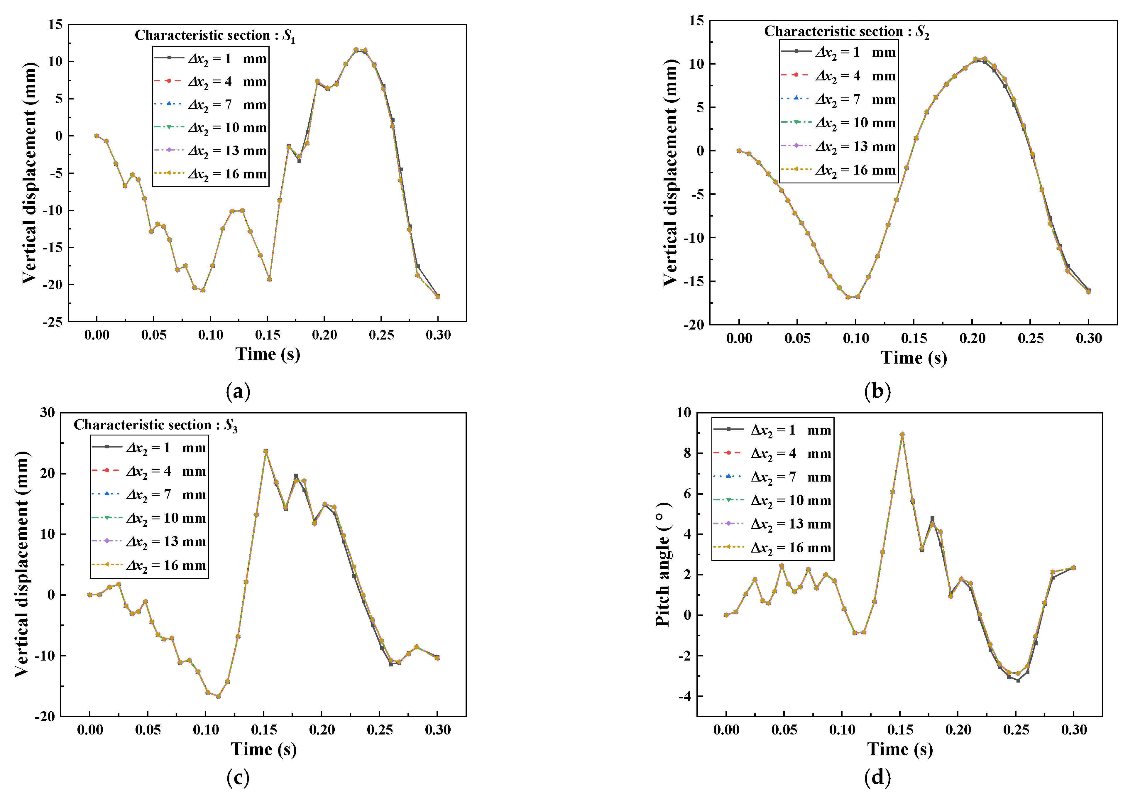
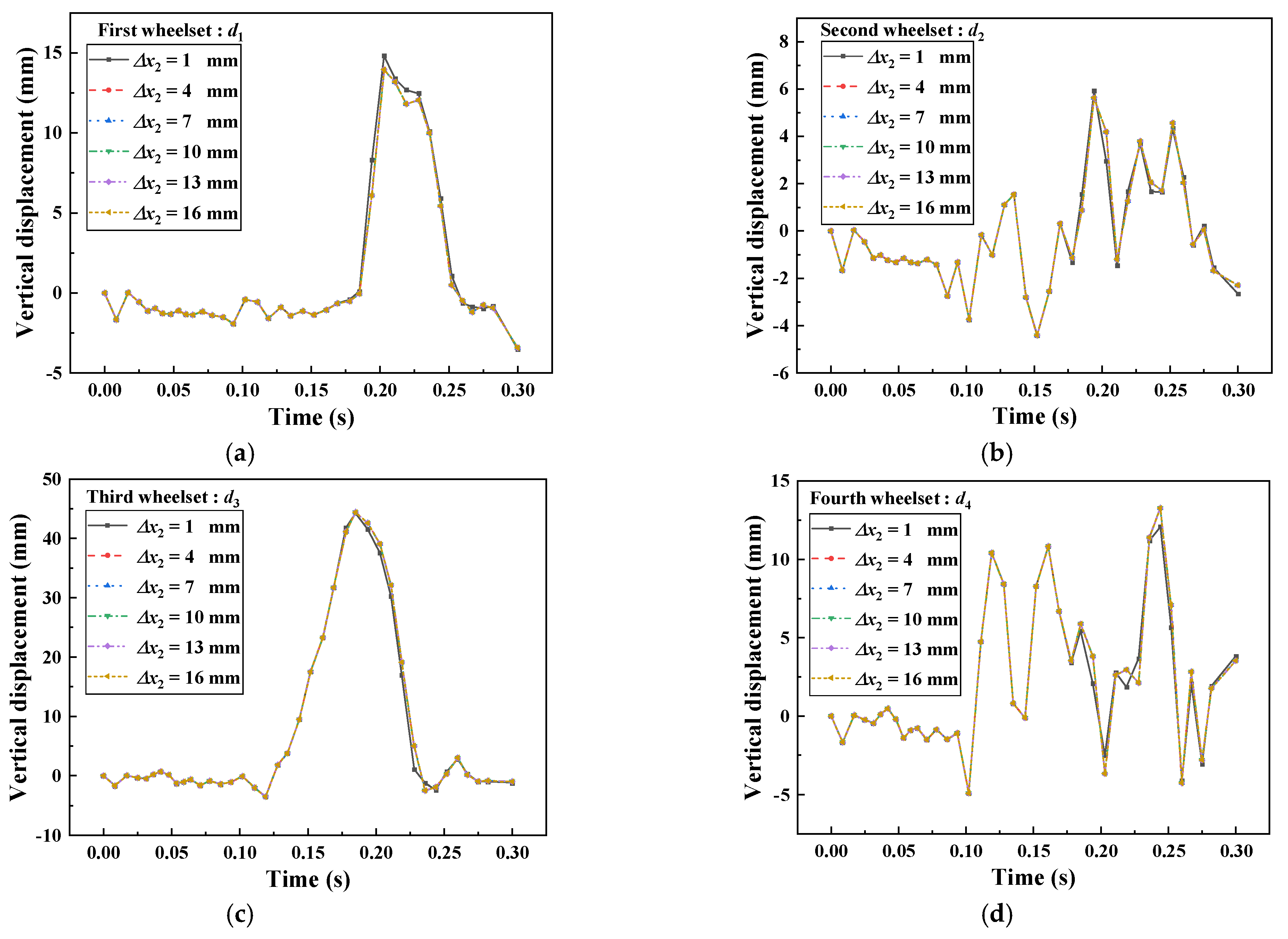
To discuss the effect of Δ x 2 on the car body attitude and wheelset lift, the Δ x 2 is equally divided into six groups (1 mm, 4 mm, 7 mm, 10 mm, 13 mm, 16 mm); x 1 , k 1 and k 2 are set to 10 mm, 20,000 N/mm and 100,000 N/mm, respectively. The vertical lift of the wheelset and the change of the body attitude are shown in Figure 21 and Figure 22.
Figure 21a shows that with the increase in linear stage distance Δ x 2 , the vertical lift of feature section S1 remains basically the same; Figure 21b illustrates that the maximum vertical lift of feature section S2 increases slightly with the increase in Δ x 2 and when Δ x 2 is greater than 4 mm, the vertical lift basically does not show a large change; Figure 21c shows that with the increase in Δ x 2 , the vertical lift of feature section S3 remains basically the same; Figure 21d illustrates that with the increase in Δ x 2 , the maximum pitch angle of the vehicle does not show a large change, which indicates that the influence of the sexual stage distance on the attitude of the vehicle is not significant.
Figure 22a shows that the maximum vertical lift of the first wheelset decreases slightly with the increase in the linear stage distance Δ x 2 , the maximum vertical lift of the first wheelset does not change after the linear stage distance Δ x 2 is greater than 4 mm. Figure 22b shows that the vertical lift of the third pair remains essentially unchanged as the linear stage distance increases; Figure 22c shows that the vertical lift of the third wheelset remains the same with the increase in linear stage distance Δ x 2 ; Figure 22d shows that the maximum vertical lift of the fourth wheelset increases slightly with the increase in linear stage distance Δ x 2 , the maximum vertical lift of the fourth wheelset does not change after the linear stage distance Δ x 2 is greater than 4 mm.
In general, with the increase in the linear stage distance Δ x 2 , the maximum vertical lift and the pitch angle of the three characteristic sections of the car body basically do not change much, and the crash attitude of the train does not improve; when the linear stage distance Δ x 2 reaches 4 mm, the maximum lift of the four wheelsets of the train does not change much with the change of the linear stage distance. Therefore, it can be found that the linear stage distance has little effect on the train’s crash attitude and wheelsets vertical lift.

4.3. Effect of the Stiffness of Linear Stage of k1

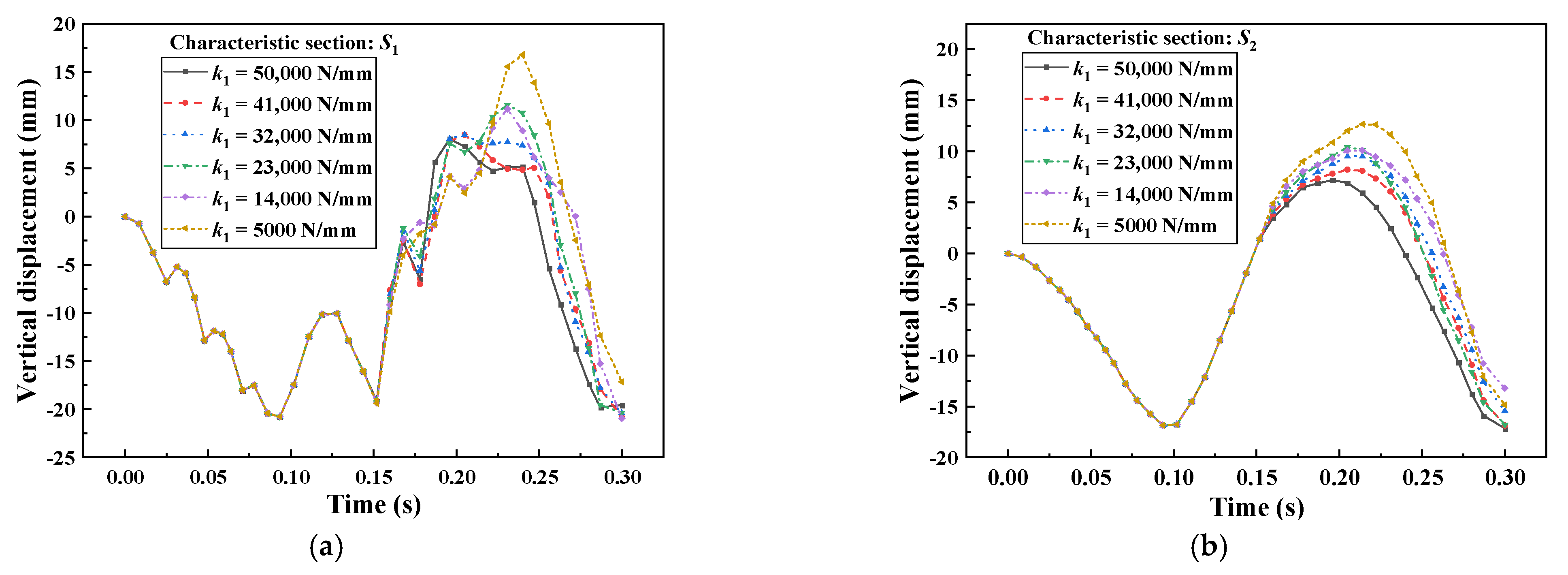
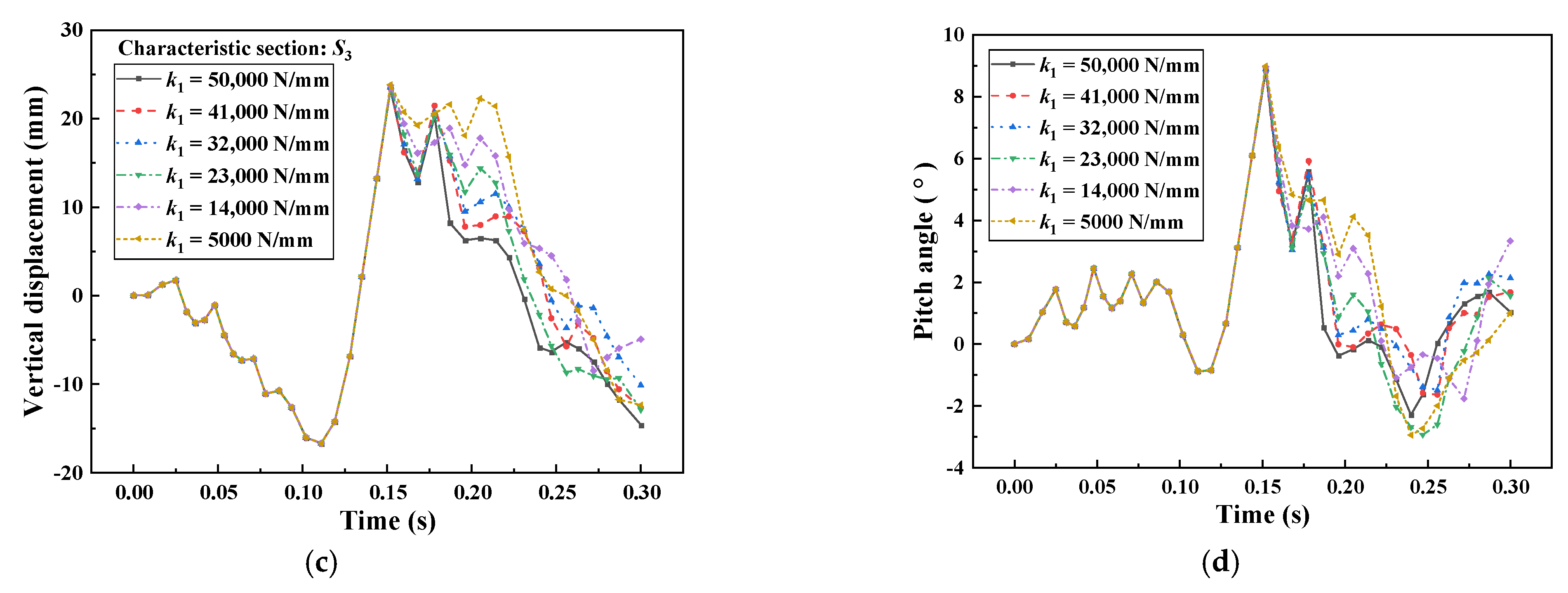
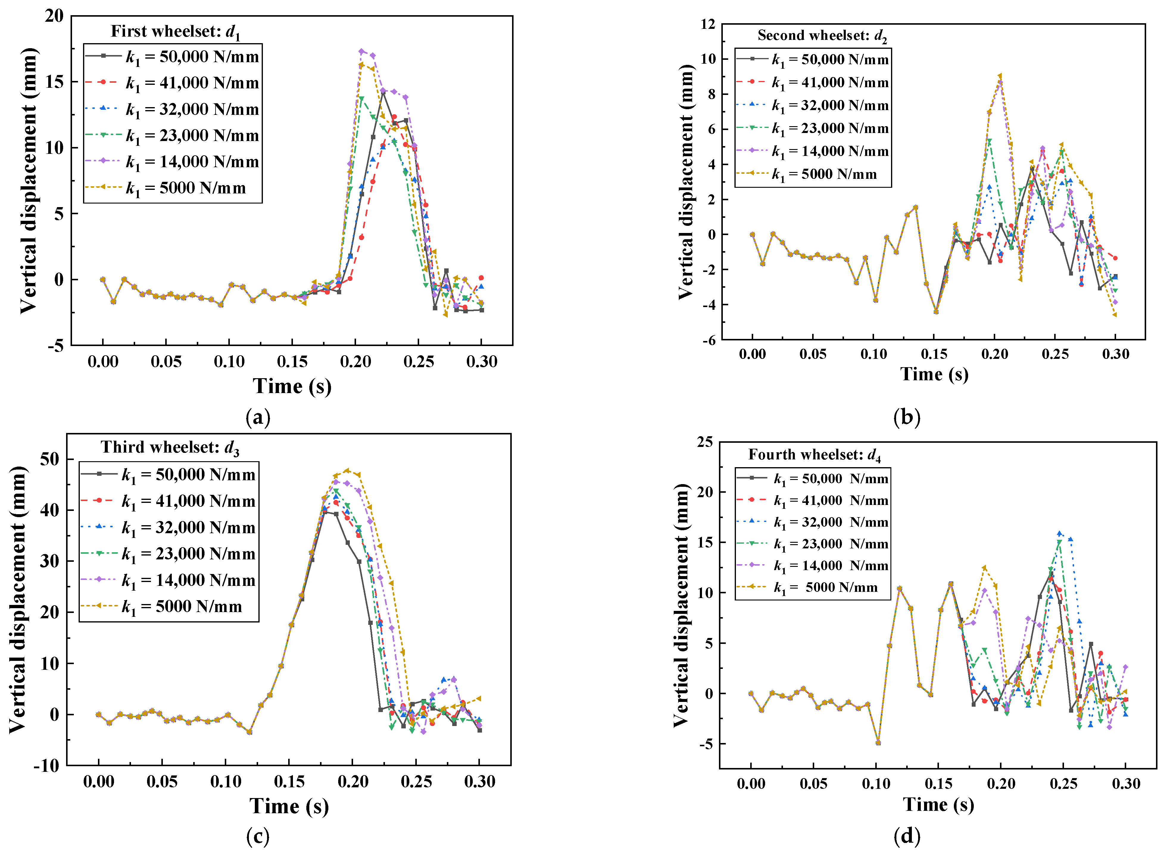
To discuss the effects on the car body attitude and wheelset lift, the k 1 is equally divided into six groups (5000 N/mm, 14,000 N/mm, 23,000 N/mm, 32,000 N/mm, 41,000 N/mm, 50,000 N/mm); x 1 , Δ x 2 and k 2 are set to 10 mm, 10 mm and 100,000 N/mm, respectively. The vertical lift of the wheelset and the change of the body attitude are demonstrated in Figure 23 and Figure 24.
Figure 23a shows that the maximum vertical lift of feature section S1 decreases continuously with the increase in k 1 , and it is found that the peak of the vertical lift of feature section S1 appears earlier with the increase in k 1 ; Figure 23b illustrates that the maximum vertical lift of feature section S2 decreases continuously with the increase in k 1 ; Figure 23c shows that the maximum vertical lift of feature section S3 will not show a large change as k 1 increases, but the vertical lift of feature section S3 gets a significant decrease as k 1 increases within 0.15–0.3 s; Figure 23d illustrates that the maximum pitch angle of the car body will not show a large change as k 1 increases, but the pitch angle shows a significant decrease after 0.15 s, indicating that the nodding phenomenon of the car body with k 1 increases becomes less and less obvious.
Figure 24a shows that the vertical lift of the first wheelset decreases and then increases as k1 increases. Figure 24b illustrates that the maximum vertical lift of the second wheelset shows a gradual decrease with the increase in k 1 ; Figure 24c shows that the maximum vertical lift of the third wheelset gradually decreases from 50 mm to 40 mm with the increasing of k 1 , showing a negative correlation; Figure 24d illustrates that the maximum vertical lift of the fourth wheelset tends to increase and then decrease as it increases with increasing of k 1 .
In general, with the increasing of k 1 , the vertical lift of the three characteristic sections of the train and the pitch angle of the car body are decreased, which indicates that the nodding phenomenon of the train body in the collision process is alleviated, and the maximum vertical lift of the first three wheelset of the train will decrease with the increasing of k 1 , and the maximum vertical lift of the fourth wheelset will increase and then decrease. Therefore, a reasonable increase in k 1 can effectively reduce the vertical lift of the wheelsets and alleviate the nodding phenomenon of the train, and reduce the derailment and jumping of the train.

5. Conclusions

In this study, the dynamic model of the head car collision of the subway vehicle was established, and the accuracy of the dynamic model was verified through real vehicle experiments. The idea of a hook rail holding mechanism installed on the car body was proposed to control the collision attitude of the car body. To carry out parametric analysis of the rail holding mechanism, the mechanism was equivalent through the force element structure of the dynamic model, according definite the vertical evaluation index of the train, the influence of the design parameters x 1 , Δ x 2 and k 1 of the rail holding mechanism on the car body posture and wheelset lifting during the collision is emphatically analyzed, the following conclusions can be obtained:
  • The maximum vertical lift of the first three wheelsets of the train will increase with the increase in x 1 , and the maximum vertical lift of the fourth wheelsets will first decrease and then increase.
  • The vertical lift of the three characteristic sections of the car body, the pitch angle of the car body and the vertical lift of the wheelset do not change too much with the change of the linear phase distance Δ x 2 , and the linear phase distance Δ x 2 of the rail holding device has little effect on the train crash attitude and wheelset lift.
  • With the increasing of k 1 , the vertical lift of the three characteristic sections of the train and the pitch angle of the car body are decreased, and the maximum vertical lift of the first three wheelsets of the train will keep decreasing with the increasing of k 1 , and the maximum vertical lift of the fourth wheelset will appear to increase first and then decrease.
  • With the reasonable reduction of the clearance distance x 1 and increase in k 1 can effectively reduce the vertical lift of the wheelsets and alleviate the nodding phenomenon of the train, and reduce the derailment and jumping phenomenon during the train collision.

Author Contributions

Conceptualization, P.X. and L.Y.; methodology, L.Y.; software, L.Y.; validation, L.Y. and W.G.; formal analysis, P.X.; investigation, P.X.; resources, Q.C.; data curation, W.G. and T.X.; writing—original draft preparation, L.Y.; writing—review and editing, L.Y.; visualization, C.Y.; supervision, P.X.; project administration, P.X.; funding acquisition, P.X. All authors have read and agreed to the published version of the manuscript.

Funding

This work was supported by Changsha Municipal Natural Science Foundation [No. kq2202102], the Hunan Provincial Natural Science Foundation of China [No. 2022JJ40619], the National Key Research and Development Program of China [No. 2021YFB3703801], the Scientific Research Foundation for Young Scholars of Central South University [No. 202044019], and Leading talents of science and technology of Hunan Province [No. 2019RS3018].

Institutional Review Board Statement

Not applicable.

Informed Consent Statement

Not applicable.

Data Availability Statement

The data used to support the findings of this study are available from the corresponding author upon request.

Conflicts of Interest

The authors declare no conflict of interest.

References

  1. Baykasoğlu, C.; Sünbüloğlu, E.; Bozdağ, S.E.; Aruk, F.; Toprak, T.; Mugan, A. Railroad passenger car collision analysis and modifications for improved crashworthiness. Int. J. Crashworthiness 2011, 16, 319–329. [Google Scholar] [CrossRef]
  2. Sutton, A. The development of rail vehicle crashworthiness. Proc. Inst. Mech. Eng. F-J. Rail Rapid Transit 2002, 216, 97–108. [Google Scholar] [CrossRef]
  3. ASME RT-2–2014. Safety Standard for Structural Requirements for Heavy Rail Transit Vehicles. The American Society of Mechanical Engineers: New York, NY, USA, 2014.
  4. EN 15227: 2020; Railway Applications Crashworthiness Requirements for Railway Vehicle Bodies. British Standard Published; European Committee for Standardization: London, UK, 2020.
  5. Li, Y. China Youth Daily. 2022. Available online: http://news.cyol.com/gb/articles/2022-06/04/content_zXzgwCYZo.html (accessed on 4 June 2022).
  6. Lu, S.; Wang, P.; Ni, W.; Yan, K.; Zhao, S.; Yang, C.; Xu, P. Energy absorption design for crash energy management passenger trains based on scaled model. Struct. Multidiscipl. Optim. 2021, 65, 1–17. [Google Scholar] [CrossRef]
  7. Zhang, H.; Peng, Y.; Hou, L.; Wang, D.; Tian, G.; Li, Z. Multistage Impact Energy Distribution for Whole Vehicles in High-Speed Train Collisions: Modeling and Solution Methodology. IEEE Trans. Ind. Inform. 2020, 16, 2486–2499. [Google Scholar] [CrossRef]
  8. Gao, G.; Dong, H.; Tian, H. Collision performance of square tubes with diaphragms. Thin-Walled Struct. 2014, 80, 167–177. [Google Scholar] [CrossRef]
  9. Peng, Y.; Wang, S.; Yao, S.; Xu, P. Crashworthiness analysis and optimization of a cutting-style energy absorbing structure for subway vehicles. Thin-Walled Struct. 2017, 120, 225–235. [Google Scholar] [CrossRef]
  10. Peng, Y.; Wang, X.; Xiong, X.; Xu, P. Crashing analysis and multi-objective optimisation of duplex energy-absorbing structure for subway vehicle. Int. J. Crashworthiness 2016, 21, 338–352. [Google Scholar] [CrossRef]
  11. Xie, S.; Liang, X.; Zhou, H. Design and analysis of a composite energy-absorbing structure for use on railway vehicles. Proc. Inst. Mech. Eng. F-J. Rail Rapid Transit 2015, 230, 825–839. [Google Scholar] [CrossRef]
  12. Xu, P.; Xing, J.; Yao, S.; Yang, C.; Chen, K.; Li, B. Energy distribution analysis and multi-objective optimization of a gradual energy-absorbing structure for subway vehicles. Thin-Walled Struct. 2017, 115, 255–263. [Google Scholar] [CrossRef]
  13. Deng, G.; Wang, F.; Yu, C.; Peng, Y.; Xu, H.; Li, Z.; Wang, Z. Assessment of standing passenger traumatic brain injury caused by ground impact in subway collisions. Accid. Anal. Prev. 2022, 166, 106547. [Google Scholar] [CrossRef]
  14. Hou, L.; Peng, Y.; Sun, D. Neck injury mechanisms in train collisions: Dynamic analysis and data mining of the driver impact injury. Accid. Anal. Prev. 2020, 146, 105725. [Google Scholar] [CrossRef] [PubMed]
  15. Wei, L.; Zhang, L. Evaluation and improvement of crashworthiness for high-speed train seats. Int. J. Crashworthiness 2017, 23, 561–568. [Google Scholar] [CrossRef]
  16. Yang, W.; Xie, S.; Li, H.; Chen, Z. Design and injury analysis of the seated occupant protection posture in train collision. Saf. Sci. 2019, 117, 263–275. [Google Scholar] [CrossRef]
  17. Yao, S.; Li, X.; Xiao, X.; Xu, P.; Che, Q. Injuries to standing passengers using different handrails in subway train collision accidents. Int. J. Crashworthiness 2019, 26, 53–64. [Google Scholar] [CrossRef]
  18. Zhang, J.; Zhu, T.; Yang, B.; Wang, X.; Xiao, S.; Yang, G.; Li, Y.; Li, B. Influence of wheelset rotational motion on train collision response and wheelset lift mechanism. Int. J. Rail Transp. 2022, 1–25. [Google Scholar] [CrossRef]
  19. Zhang, T.; Guo, X.; Jin, T.; Yang, Y.; Ling, L.; Wang, K.; Zhai, W. Dynamic derailment behavior of urban tram subjected to lateral collison. Int. J. Rail Transp. 2022, 10, 581–605. [Google Scholar] [CrossRef]
  20. Xu, P.; Yang, C.; Peng, Y.; Yao, S.; Zhang, D.; Li, B. Crash performance and multi-objective optimization of a gradual energy-absorbing structure for subway vehicles. Int. J. Mech. Sci. 2016, 107, 1–12. [Google Scholar] [CrossRef]
  21. Guan, W.; Gao, G.; Li, J.; Yu, Y. Crushing analysis and multi-objective optimization of a cutting aluminium tube absorber for railway vehicles under quasi-static loading. Thin-Walled Struct. 2018, 123, 395–408. [Google Scholar] [CrossRef]
  22. Peng, Y.; Deng, W.; Xu, P.; Yao, S. Study on the collision performance of a composite energy-absorbing structure for subway vehicles. Thin-Walled Struct. 2015, 94, 663–672. [Google Scholar] [CrossRef]
  23. Kirkpatrick, S.W.; MacNeill, R.A. Development of a computer model for prediction of collision response of a railroad passenger car. In Proceedings of the ASME/IEEE Joint Rail Conference, Washington, DC, USA, 23–25 April 2002. [Google Scholar]
  24. Tyrell, D.; Jacobsen, K.; Martinez, E.; Perlman, A.B. Train-to-Train Impact Test of Crash Energy Management Passenger Rail Equipment: Structural Results. In Proceedings of the ASME 2006 International Mechanical Engineering Congress and Exposition, Chicago, IL, USA, 5–10 November 2006; The American Society of Mechanical Engineers: New York, NY, USA, 2006. [Google Scholar]
  25. Liu, Y.; Yang, B.; Li, B.; Xiao, S.; Zhu, T.; Yang, G.; Xiu, R. Experimental and numerical investigation of the design strategy of new anticollision posts for a typical railway vehicle. Int. J. Rail Transp. 2021, 10, 772–799. [Google Scholar] [CrossRef]
  26. Li, B.; Lu, Z.; Yan, K.; Lu, S.; Kong, L.; Xu, P. Experimental study of a honeycomb energy-absorbing device for high-speed trains. Proc. Inst. Mech. Eng. F-J. Rail Rapid Transit 2019, 234, 1170–1183. [Google Scholar] [CrossRef]
  27. Li, S.; Zheng, Z. Energy-absorbing structure design and crashworthiness analysis of high-speed trains. Explos. Shock Waves 2015, 35, 164–170. [Google Scholar]
  28. Yang, C.; Xu, P.; Yao, S.; Xie, S.; Li, Q.; Peng, Y. Optimization of honeycomb strength assignment for a composite energy-absorbing structure. Thin-Walled Struct. 2018, 127, 741–755. [Google Scholar] [CrossRef]
  29. Zhang, Z.; Yao, S.; Xu, P.; Peng, Y.; Zhang, Y. High-speed train car body front-end energy-absorbing structure of crash simulation and experiment. Locomot. Roll. Stock Technol. 2015, 3, 33–34, 43. [Google Scholar]
  30. Zhang, Y.; Xu, P.; Peng, Y.; Deng, L.; Che, Q. Crashworthiness optimization of high-speed train front multi-cell energy-absorbing structure. J. Vib. Shock 2017, 36, 31–36. [Google Scholar]
  31. Baharudin, M.E.; Rouvinen, A.; Korkealaakso, P.; Mikkola, A. Real-time multibody application for tree harvester truck simulator. Proc. Inst. Mech. Eng. Part K J. Multi-Body Dyn. 2014, 228, 182–198. [Google Scholar] [CrossRef]
  32. Wu, X.; Chi, M.; Gao, H. The study of post-derailment dynamic behavior of railway vehicle based on running tests. Eng. Fail. Anal. 2014, 44, 382–399. [Google Scholar] [CrossRef]
  33. Ling, L.; Xiao, X.; Jin, X.-S. Development of a simulation model for dynamic derailment analysis of high-speed trains. Acta Mech. Sin. 2015, 30, 860–875. [Google Scholar] [CrossRef]
  34. Ling, L.; Dhanasekar, M.; Wang, K.; Zhai, W.; Weston, B. Collision derailments on bridges containing ballastless slab tracks. Eng. Fail. Anal. 2019, 105, 869–882. [Google Scholar] [CrossRef]
  35. Liu, Y.; Yang, B.; Xiao, S.; Zhu, T.; Yang, G.; Xiu, R. Parameter study and multi-objective optimization for crashworthiness of a B-type metro train. Proc. Inst. Mech. Eng. F-J. Rail Rapid Transit 2021, 236, 91–108. [Google Scholar] [CrossRef]
  36. Li, R.; Xu, P.; Peng, Y.; Xie, Y. Scaled tests and numerical simulations of rail vehicle collisions for various train sets. Proc. Inst. Mech. Eng. F-J. Rail Rapid Transit 2015, 230, 1590–1600. [Google Scholar] [CrossRef]
  37. Lu, S.; Xu, P.; Yan, K.; Yao, S.; Li, B. A force/stiffness equivalence method for the scaled modelling of a high-speed train head car. Thin-Walled Struct. 2019, 137, 129–142. [Google Scholar] [CrossRef]
  38. Yao, S.; Yan, K.; Lu, S.; Xu, P. Energy-absorption optimisation of locomotives and scaled equivalent model validation. Int. J. Crashworthiness 2017, 22, 441–452. [Google Scholar] [CrossRef]
  39. Wu, X.; Chi, M.; Gao, H.; Zhang, D.; Zeng, J.; Wu, P.; Zhu, M. The study of post-derailment measures to limit the extent of a derailment. Proc. Inst. Mech. Eng. F-J. Rail Rapid Transit 2014, 230, 64–76. [Google Scholar] [CrossRef]
  40. Yang, C.; Li, D.; Zhu, T.; Xiao, S. Special dynamic behavior of an aluminum alloy and effects on energy absorption in train collisions. Adv. Mech. Eng. 2016, 8. [Google Scholar] [CrossRef] [Green Version]
  41. Lai, J.; Xu, J.; Liao, T.; Zheng, Z.; Chen, R.; Wang, P. Investigation on train dynamic derailment in railway turnouts caused by track failure. Eng. Fail. Anal. 2022, 134, 106050. [Google Scholar] [CrossRef]
  42. Xu, J.; Wang, J.; Wang, P.; Chen, J.; Gao, Y.; Chen, R.; Xie, K. Study on the derailment behaviour of a railway wheelset with solid axles in a railway turnout. Veh. Syst. Dyn. 2019, 58, 123–143. [Google Scholar] [CrossRef]
  43. Ren, Y. The Influence of the Initial States of the Train on the Collision Responses. Master’s Thesis, Southwest Jiaotong University, Chengdu, China, 2019. [Google Scholar] [CrossRef]
  44. Yang, C.; Li, Q.; Wang, X.; Wang, M. Overriding Behavior in Train Collisions Based on Moving Vehicle-Track Coupled Model. J. Southwest Jiaotong Univ. 2019, 54, 1298–1304. [Google Scholar]
  45. Lv, R. Impact Characteristics of Metro Trains Coupler and Draft Gears and Its Effect on Derailment Behavior. Master’s Thesis, Southwest Jiaotong University, Chengdu, China, 2021. [Google Scholar] [CrossRef]
  46. Zhai, W.; Wang, K.; Cai, C. Fundamentals of vehicle–track coupled dynamics. Veh. Syst. Dyn. 2009, 47, 1349–1376. [Google Scholar] [CrossRef]
  47. Ling, L.; Xiao, X.; Xiong, J.; Zhou, L.; Wen, Z.; Jin, X. A 3D model for coupling dynamics analysis of high-speed train/track system. J. Zhejiang Univ.-Sci. A 2015, 16, 170. [Google Scholar] [CrossRef] [Green Version]
  48. Marquis, B.; Pascal, J.P. Report on a railway Benchmark simulating a single wheelset without friction impacting a rigid track. Veh. Syst. Dyn. 2008, 46, 93–116. [Google Scholar] [CrossRef]
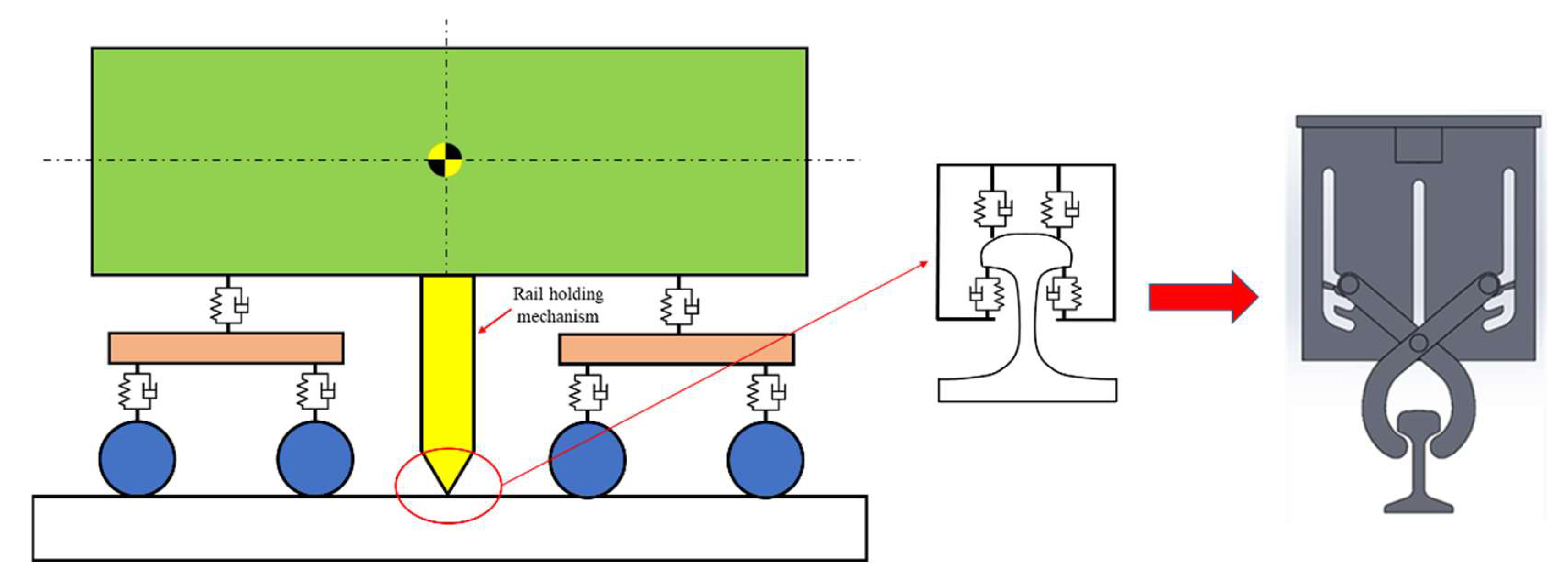
Figure 1. Dynamic topological model of the rail holding mechanism.
Machines 10 01231 g001
Figure 2. Force element characteristic curve of the rail holding mechanism.
Machines 10 01231 g002
Figure 3. Schematic diagram of the bogie displacement distribution definition.
Machines 10 01231 g003
Figure 4. Schematic diagram of each characteristic section and key node position of car body.
Machines 10 01231 g004
Figure 5. Subway vehicle system dynamics model based on multi–rigid body theory.
Machines 10 01231 g005
Figure 6. Nonlinear property of the secondary yaw damper.
Machines 10 01231 g006
Figure 7. Nonlinear performance of the bump-stop.
Machines 10 01231 g007
Figure 8. Nonlinear characteristics of the coupler.
Machines 10 01231 g008
Figure 9. Vehicle dynamics model constructed with reference to subway vehicles.
Machines 10 01231 g009
Figure 10. Impact force characteristic curve: (a) coupler and car body energy absorption characteristics curve; (b) anti–climbers energy absorption characteristic curve.
Machines 10 01231 g010
Figure 11. Schematic diagram of subway vehicle collision.
Machines 10 01231 g011
Figure 12. Collision circuit system: (a) crash test system scene diagram; (b) lighting system; (c) photograph.
Machines 10 01231 g012
Figure 13. High-speed camera position layout.
Machines 10 01231 g013
Figure 14. Comparison between experiment and simulation: (a) Velocity–Time curve; (b) Longitudinal displacement–Time curve; (c) Vertical displacement–Time curve; (d) Longitudinal acceleration–Time curve.
Machines 10 01231 g014aMachines 10 01231 g014b
Figure 15. Comparison of experiment and simulation deformation sequences: (a) anti–climbing energy absorption contact stage (t = 0 s); (b) driver’s cab contact stage (t = 0.025 s); (c) energy absorption structure compressed to the maximum (t = 0.175 s); (d) end of collision stage (t = 0.3 s).
Machines 10 01231 g015aMachines 10 01231 g015b
Figure 16. Comparison of the characteristic cross–sectional lift of the train before and after the installation of rail holding mechanism: (a) without rail holding mechanism; (b) with rail holding mechanism.
Machines 10 01231 g016
Figure 17. Comparison of wheelset lift before and after installation of rail holding mechanism: (a) without rail holding mechanism; (b) with rail holding mechanism.
Machines 10 01231 g017
Figure 18. Comparison of the pitch angle of the car body.
Machines 10 01231 g018
Figure 19. Lift and pitch angle of the characteristic section of the car body at different clearance distances x1: (a) vertical lift of the characteristic section S1; (b) vertical lift of the characteristic section S2; (c) vertical lift of the characteristic section S3; (d) pitch angle of the center of mass of the car body.
Machines 10 01231 g019
Figure 20. Vertical lift of wheelsets at different x1: (a) vertical lift of the first wheelsets (d1); (b) vertical lift of the second wheelsets (d2); (c) vertical lift of the third wheelset (d3); (d) vertical lift of the fourth wheelsets (d4).
Machines 10 01231 g020
Figure 21. Lift and pitch angle of the characteristic section of the car body at different linear phase distances: (a) vertical lift of the characteristic section S1; (b) vertical lift of the characteristic section S2; (c) vertical lift of the characteristic section S3; (d) pitch angle of the center of mass of the car body.
Machines 10 01231 g021
Figure 22. Vertical lift of wheelsets at different linear phase distances Δ x 2 : (a) vertical lift of the first wheelsets (d1); (b) vertical lift of the second wheelsets (d2); (c) vertical lift of the third wheelset (d3); (d) vertical lift of the fourth wheelsets (d4).
Machines 10 01231 g022
Figure 23. Lift and pitch angle of the characteristic section of the car body at different k 1 : (a) vertical lift of the characteristic section S1; (b) vertical lift of the characteristic section S2; (c) vertical lift of the characteristic section S3; (d) pitch angle of the center of mass of the car body.
Machines 10 01231 g023aMachines 10 01231 g023b
Figure 24. Vertical lift of wheelsets at different k1: (a) vertical lift of the first wheelsets (d1); (b) vertical lift of the second wheelsets (d2); (c) vertical lift of the third wheelset (d3); (d) vertical lift of the fourth wheelsets (d4).
Machines 10 01231 g024
Table 1. Basic parameters of the subway vehicle.
TypeParametersUnitValue
Position parametersVehicle distancemm13,368
Bogie axis distancemm5032
Rail distancemm1435
Wheel rolling circle diametermm860
Wheelset distancemm2516
vehicle parameterCarbody masst34
Carbody moment of inertia-Xkg·m26.67 × 107
Carbody moment of inertia-Ykg·m21.06 × 109
Carbody moment of inertia-Zkg·m21,349,239
Bogie masst2.66
Bogie moment of inertia-Xkg·m21.29 × 106
Bogie moment of inertia-Ykg·m21.038 × 106
Bogie moment of inertia-Zkg·m22.18 × 106
Wheelset masst1.2
Wheelset moment of inertia-Xkg·m28.59 × 105
Wheelset moment of inertia-Ykg·m21.57 × 105
Carbody moment of inertia-Zkg·m28.72 × 106
Suspension parametersAxlebox spring longitudinal stiffnessN/mm13,150
Axlebox spring lateral stiffnessN/mm13,150
Axlebox spring vertical stiffnessN/mm3800
Primary suspension vertical damperN·s/mm20
Airspring longitudinal stiffnessN/mm2500
Airspring lateral stiffnessN/mm2500
Airspring vertical stiffnessN/mm3800
Secondary suspension longitudinal damperN·s/mm810
Secondary suspension lateral damperN·s/mm15
Secondary suspension vertical damperN·s/mm10
Table 2. Information of test and test instruments.
NumberInstrumentModelBrand
1Dynamic data collectorKi-DAUKistler (Winterthur, Switzerland)
2Motion sensorMT2ACelesco (Chatsworth, CA, USA)
3Acceleration sensor7264H-360ENDEVCO (San Juan Capistrano, CA, USA)
4Tape measureA0481TaJima (Tokyo, Japan)
5PhotographHX-6ENAC (Salem, MA, USA)
Publisher’s Note: MDPI stays neutral with regard to jurisdictional claims in published maps and institutional affiliations.