Article

Rigid-Body Guidance Synthesis of Noncircular Gear-Five-Bar Mechanisms and Its Application in a Knee Joint Rehabilitation Device

1
School of Mechanical Engineering, Zhejiang Sci-Tech University, Hangzhou 310018, China
2
Faculty of Mechanical Engineering, Zhejiang Industry Polytechnic College, Shaoxing 312000, China
3
Key Laboratory of Transplanting Equipment and Technology of Zhejiang Province, Hangzhou 310018, China
*
Author to whom correspondence should be addressed.
Machines 2022, 10(12), 1110; https://doi.org/10.3390/machines10121110
Submission received: 21 October 2022 / Revised: 14 November 2022 / Accepted: 19 November 2022 / Published: 22 November 2022
(This article belongs to the Section Machine Design and Theory)

Abstract

:
At present, the research objects of rigid-body guidance synthesis are mostly limited to pure linkages, and there is little research on the combined mechanisms of gears or cams and linkages. In order to expand the research objects of rigid-body guidance and improve the kinematic mapping theory, this paper proposes a rigid-body guidance method of noncircular gear-five-bar combined mechanisms. A noncircular gear-five-bar mechanism can be regarded as a combination of a 2R (two revolute joints) open chain, a 3R (three revolute joints) open chain and a pair of noncircular gears. Firstly, the circle point curves and circle center point curves of the 2R and 3R open chains are obtained by using kinematic mapping, and they are formed into a double crank five-bar linkage. Secondly, the B-spline curve is used to fit the rotation angle relationship of the gear pair to obtain the pitch curves of noncircular gears. Finally, aiming at correcting patients’ abnormal gait, a noncircular gear-five-bar exoskeleton knee joint rehabilitation device is designed based on four task poses. The prototype is developed and the wear test is carried out. The test results verify the correctness of the rigid-body guidance synthesis method and the effectiveness of rehabilitation training.

1. Introduction

Path synthesis, function synthesis and rigid-body guidance synthesis constitute three major contents of dimension synthesis of linkage mechanisms, which are the research hotspots of mechanism science. Among them, rigid-body guidance synthesis is to guide a certain component of a machine or mechanism to pass through a number of given poses in sequence, and scholars have carried out much research on this. Burmester [1] first studied the motion relationships of four or five finite separated positions of a planar rigid-body and established the important Burmester curve in four-bar linkages. Han et al. [2] established the standard form of the Burmester curve and realized the single-valued ordered representation of the Burmester curve. Deshpande et al. [3] and Ge et al. [4,5] established geometric constraints to solve the Burmester problem and realized the rigid-body guidance synthesis of planar four-bar linkages. Qian et al. [6] proposed a rigid-body guidance synthesis method of a four-bar linkage with finite separation of four positions, and represented the infinite number of mechanism solutions in a limited range. Han et al. and Cui et al. [7,8] proposed the synthesis methods of six-bar and eight-bar linkages with four exact pose constraints and applied them to simulate the grasping motion of human fingers. The above research objects of rigid-body guidance synthesis are limited to planar four-bar, six-bar, eight-bar and other pure linkage mechanisms, and there is little research on the combined mechanisms of gears or cams and linkages.
Compared with the planar pure linkage mechanisms, the combined mechanisms of gears or cams and linkages can realize more diverse motions and meet more special kinematic and dynamic requirements. Shao et al. [9] realized the path synthesis of the 1-DOF (degree of freedom) cam-seven-bar mechanism and applied it to a lower limb gait rehabilitation device to simulate the normal human gait trajectory. Sun et al. [10] designed the prosthetic knee joint based on the gear-five-bar mechanism. This prosthetic knee joint can fine-tune the relative instantaneous rotation center and the ankle joint trajectory, and its bionic performance is better than that of the prosthetic knee joint using a four-bar linkage. Modeler et al. [11] considered all types of gear-five-bar mechanisms and proposed a general synthesis method for designing the desired transmission function, which is often highly nonlinear. Mundo et al. [12] proposed an exact path synthesis method of noncircular gear-five-bar mechanisms and gave an example of exactly realizing the path synthesis of a noncircular gear-five-bar mechanism along two parallel lines. After much literature review, it can be seen that most of the existing research on the motion synthesis of noncircular gear-five-bar mechanisms focus on path synthesis and function synthesis, and there is little research on rigid-body guidance synthesis. This paper mainly studies the rigid-body guidance synthesis of noncircular gear-five-bar mechanisms with four exact pose constraints and broadens the research field of motion synthesis of noncircular gear-five-bar mechanisms.
The synthesis methods of rigid-body guidance of mechanisms mainly include the graphical method [13,14], atlas method [15,16] and analytical method [17,18,19]. The graphical method for rigid-body guidance has a clear concept, but the process is cumbersome, the error is large, and all solutions cannot be obtained. It is only suitable for simple occasions with low precision requirements. In order to obtain satisfactory design results with the atlas method, a huge atlas library needs to be established in advance. At the same time, the methods of fitting and optimization are often used to calculate the actual size and installation parameters, so the approximate solutions are obtained, and the given poses cannot be accurately passed. The analytical method uses a mathematical model to analyze the inherent characteristics of the mechanism motion. The linkage solution region synthesis method [20] and the kinematic mapping method [21] are the two most important analytical methods and are also the mainstream methods for solving the rigid-body guidance synthesis problem. The solution region synthesis method is mainly aimed at the accurate design of four or five poses of the closed chain mechanisms, and its application scope is limited. The kinematic mapping synthesis method can not only solve the closed chain mechanisms, but also solve the multi-pose synthesis problem of the open chain mechanisms, which is more widely used. The kinematic mapping synthesis method transforms the plane motion from the two-dimensional plane expression to the four-dimensional motion space expression, studies the constrained manifold of the plane two-bar groups in the four-dimensional motion space, and then solves the problem through the constrained manifold. Li et al. [22] used planar quaternions to map planar displacements from Cartesian space to image space, and developed a unified algorithm for synthesizing various four-bar linkages. Purwar et al. [23] proposed a unified framework for synthesizing the types and dimensions of planar four-bar linkages based on kinematic mapping, which can be used for various pose and pivot constraints. Zhao et al. [24] realized the five pose motion synthesis problems of four-bar and six-bar linkages based on kinematic mapping. Zhao et al. [25] applied kinematic mapping to planar discrete motion synthesis of an arbitrary number of approximated poses as well as up to four exact poses, and proposed a simultaneous type and dimensional synthesis method for mixed exact and approximate motion synthesis of three planar two-bar groups (RR, RP and PR). The kinematic mapping theory can also be well applied in the gear-linkage combination mechanisms. Yu et al. [26] improved the kinematic mapping algorithm and synthesized a 3R open chain noncircular gear-linkage mechanism for lower limb rehabilitation. Based on the kinematic mapping theory, this paper proposes a rigid-body guidance synthesis method of the noncircular gear-five-bar mechanism with four exact pose constraints, and designs and develops a lower limb exoskeleton knee joint rehabilitation device. The device has a great improvement in bionics, structure and motion performance, and meets the requirements of rehabilitation training. It can be seen that the kinematic mapping method has been well applied in the rigid-body guidance synthesis. Its advantage is that it has a wide range of applications. It can not only solve the problems of four or five exact poses, but also solve the problems of multiple approximate poses and mixed poses (including both exact and approximate pose constraints). Moreover, this method is not limited by the type of linkages, but is applicable to both closed chain and open chain mechanisms, and has great design flexibility. For path synthesis and function synthesis problems, the algorithm needs to be further improved.
The remainder of this paper is organized as follows. The rigid-body guidance synthesis method of noncircular gear-five-bar mechanisms based on kinematic mapping is introduced in the upcoming section. Next, the correctness of the proposed synthesis method is verified through an example of a knee joint rehabilitation device. Finally, some conclusions are presented briefly.

2. Materials and Methods

2.1. Introduction to Kinematic Mapping

Kinematic mapping is a special mathematical mapping method which transforms the motion poses containing two dimensions of plane coordinates and angles into dimensionless points in mapping space, and transforms the geometric constraints into surface manifolds in the mapping space. The core of this method is to map the poses represented by three parameters d 1 , d 2 , φ in the plane to the points represented by four parameters X 1 , X 2 , X 3 , X 4 in the space, as shown in Figure 1.
As shown in Figure 2, the motion of a rigid-body in a plane can be regarded as the translation of a point on the rigid-body to point M ( d 1 , d 2 ) and rotation of angle φ . A fixed coordinate system O X Y and a moving coordinate system M x y are established, respectively, on the origin point O of the plane and point M of the rigid-body. A point ( x , y ) in the moving coordinate system can be represented as a point ( X , Y ) in the fixed coordinate system through coordinate transformation. The relationship is as follows:
X Y 1 = cos φ sin φ d 1 sin φ cos φ d 2 0 0 1 x y 1
The planar pose ( d 1 , d 2 , φ ) is expressed on the four-dimensional space by quaternion ( Z 1 , Z 2 , Z 3 , Z 4 ) , and the mapping is shown in Equation (2):
Z 1 = 0.5 ( d 1 sin ( 0.5 φ ) d 2 cos ( 0.5 φ ) ) Z 2 = 0.5 ( d 1 cos ( 0.5 φ ) + d 2 sin ( 0.5 φ ) ) Z 3 = sin ( 0.5 φ ) Z 4 = cos ( 0.5 φ )
According to Equation (2), Equation (1) can be expressed as Equation (3):
X Y 1 = Z 4 2 Z 3 2 2 Z 4 Z 3 2 ( Z 1 Z 3 + Z 2 Z 4 ) 2 Z 4 Z 3 Z 4 2 Z 3 2 2 ( Z 2 Z 3 Z 1 Z 4 ) 0 0 Z 3 2 + Z 4 2 x y 1

2.2. Rigid-Body Guidance of Noncircular Gear-Five-Bar Mechanism with Four Exact Pose Constraints

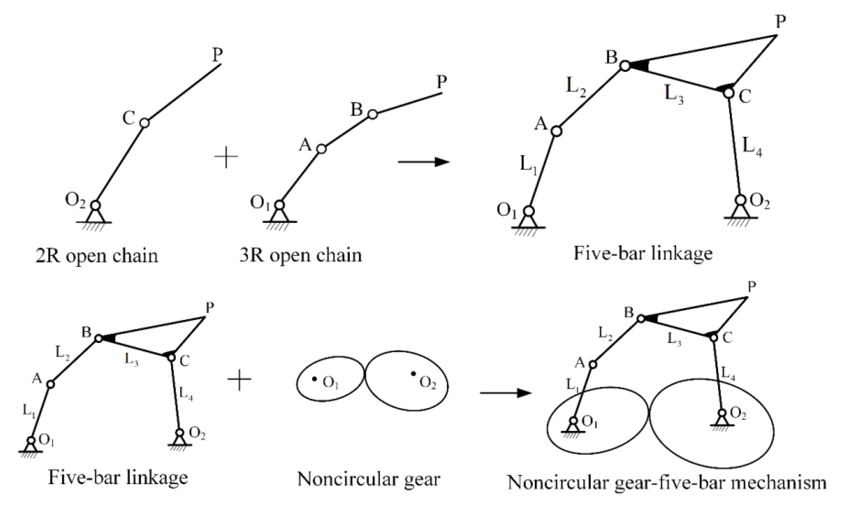
As shown in Figure 3, a five-bar linkage is regarded as composed of a 2R open chain and a 3R open chain, and the noncircular gears are used to match the angular motion relationship of the input components of the five-bar linkage. Firstly, a number of 2R and 3R bar group solutions are obtained by kinematic mapping, and a group of 2R and 3R solutions are selected to form a five-bar linkage. At the same time, the two side links of the five-bar linkage must be cranks. Then, the pitch curves of noncircular gears are generated by combining the relationship between two crank angles and the generation theory of gear pitch curves. Finally, the noncircular gear-five-bar mechanism can be combined.
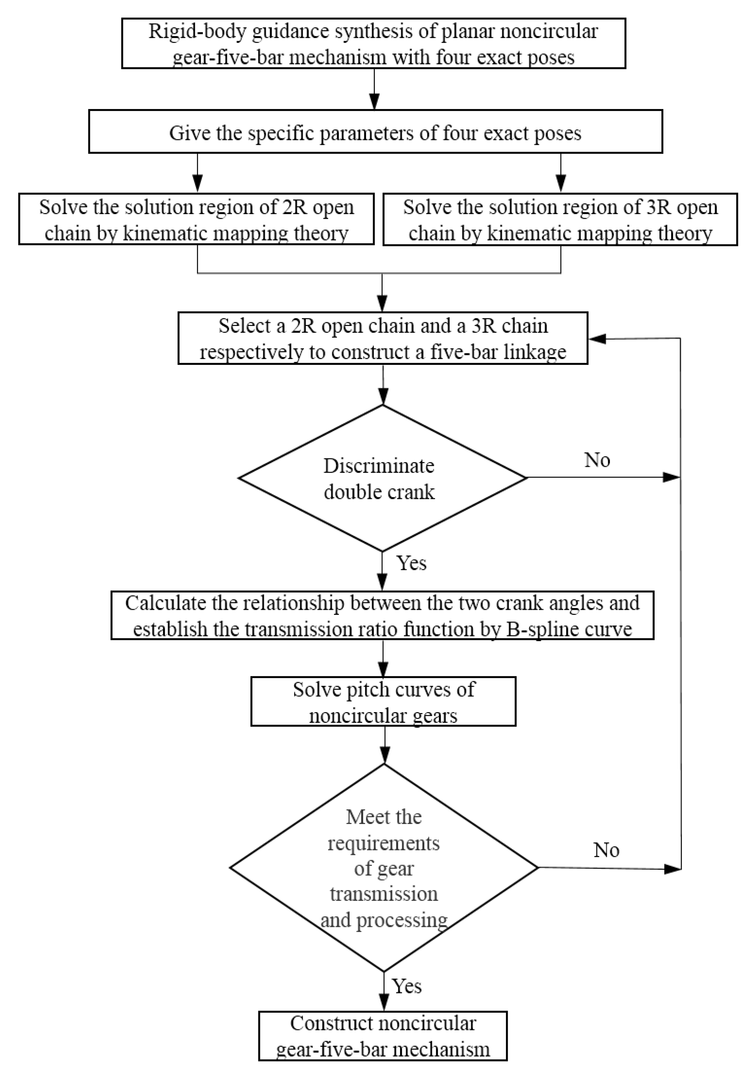
The rigid-body guidance synthesis with more than four poses can obtain few or even no solutions, which is difficult to form a general solution region and limits the optimization of mechanism parameters. The rigid-body guidance synthesis with four exact poses has infinite solutions, and the designer has plenty of choices after adding various constraints. Therefore, the rigid-body guidance synthesis of the noncircular gear-five-bar mechanism with four exact pose constraints solved in this paper has more practical engineering significance, and its synthesis process is shown in Figure 4.

2.2.1. Synthesis of Five-Bar Linkages

For a 2R open chain, the kinematic constraint it represents is that a specific point in the moving coordinate system always falls on a circle in the fixed coordinate system. Assuming that the coordinates of the moving point are ( x , y ) , and the corresponding coordinates in the fixed coordinate system are ( X , Y ) , then the equation of the circle can be expressed as:
a 0 ( X 2 + Y 2 ) + 2 a 1 X + 2 a 2 Y + a 3 = 0
where a 0 , a 1 , a 2 , a 3 are the parameters of the circle, and the radius of the circle is r = a 1 2 + a 2 2 a 0 a 3 / a 0 , a 0 0 . Substituting Equation (3) into Equation (4):
2 a 0 ( Z 1 2 + Z 2 2 ) 2 a 0 x ( Z 1 Z 3 Z 2 Z 4 ) 2 a 0 y ( Z 2 Z 3 + Z 1 Z 4 ) + 2 a 1 ( Z 1 Z 3 + Z 2 Z 4 ) + 2 a 2 ( Z 2 Z 3 Z 1 Z 4 ) + 2 ( a 2 x a 1 y ) Z 3 Z 4 ( a 1 x + a 2 y ) ( Z 3 2 Z 4 2 ) + 0.5 ( a 3 + a 0 x 2 + a 0 y 2 ) ( Z 4 2 + Z 3 2 ) = 0
In Equation (5), p 1 = 2 a 0 , p 2 = 2 a 0 x , p 3 = 2 a 0 y , p 4 = 2 a 1 , p 5 = 2 a 2 , p 6 = 2 ( a 2 x a 1 y ) , p 7 = ( a 1 x + a 2 y ) and p 8 = 0.5 ( a 3 + a 0 x 2 + a 0 y 2 ) . Parameters p i , i = 1 , 2 8 must meet the following two additional constraints:
p 1 p 6 + p 2 p 5 p 3 p 4 = 0 2 p 1 p 7 p 2 p 4 p 3 p 5 = 0
Substituting the four task poses into Equation (2) to obtain the quaternion ( Z 1 i , Z 2 i , Z 3 i , Z 4 i ) , i = 1 , 2 , 3 , 4 . Then substituting ( Z 1 i , Z 2 i , Z 3 i , Z 4 i ) into Equation (5), the linear equations can be obtained:
Ap = A 11 A 18 A 41 A 48 p 1 p 8 = 0
where A i 1 = Z i 1 2 + Z i 2 2 , A i 2 = Z i 1 Z i 3 Z i 2 Z i 4 , A i 3 = Z i 2 Z i 3 + Z i 1 Z i 4 , A i 4 = Z i 1 Z i 3 + Z i 2 Z i 4 , A i 5 = Z i 2 Z i 3 Z i 1 Z i 4 , A i 6 = Z i 3 Z i 4 , A i 7 = Z i 3 2 Z i 4 2 and A i 8 = Z i 3 2 + Z i 4 2   ( i = 1 , 2 , 3 , 4 ) .
The singular value decomposition (SVD) algorithm is used to solve the optimal fitting problem of the least square method in Equation (7). Equation (7) can be regarded as p A T A p = 0 , and solving Ap = 0 can be transformed into solving the eigenvector v of the matrix A T A . Let v 1 , v 2 , v 3 v 8 be the eight eigenvectors of the matrix A T A , and α , β , γ δ be the coefficients corresponding to the eight eigenvectors; then the general solution space p composed of v 1 , v 2 , v 3 v 8 can be expressed as:
p = α v 1 + β v 2 + γ v 3 + δ v 8
The eigenvalues corresponding to the eight eigenvectors are arranged in order from small to large, the eigenvectors corresponding to the smallest eigenvalues are taken to form the optimal general solution space p , and then the specific optimal solution satisfying Equation (6) is found in the optimal general solution space p .
According to the SVD algorithm, when taking four exact poses, the matrix A T A has four eigenvalues of zero, and the eigenvectors v 1 , v 2 , v 3 , v 4 corresponding to these four eigenvalues form a general solution space, namely:
p = α v 1 + β v 2 + γ v 3 + κ v 4
where α , β , γ , κ are four real coefficients. Substituting Equation (9) into Equation (6), two homogeneous equations of α , β , γ , κ can be obtained:
K 10 α 2 + K 11 β 2 + K 12 γ 2 + K 13 κ 2 + K 14 α β + K 15 α γ + K 16 α κ + K 17 β γ + K 18 β κ + K 19 γ κ = 0 K 20 α 2 + K 21 β 2 + K 22 γ 2 + K 23 κ 2 + K 24 α β + K 25 α γ + K 26 α κ + K 27 β γ + K 28 β κ + K 29 γ κ = 0
where K i j is determined by the elements of the four eigenvectors obtained by the SVD algorithm. In Equation (10), parameters α , β , γ , κ have infinite solutions. At this time, it is necessary to artificially add a constraint condition. Let κ be a dynamic parameter:
κ = cot ( λ ) λ ( 0 , π )
The coefficients a 0 , a 1 , a 2 , a 3 of the equation of the circle can be determined according to the obtained coefficient vector p :
a 0 : a 1 : a 2 : a 3 = p 1 : p 4 : p 5 : 4 p 8 p 1 ( p 6 2 + 4 p 7 2 ) p 4 2 + p 5 2
The equation of the circle and the two-bar group are also determined, and the specific point (circle point) in the moving coordinate system can also be obtained by p :
x = ( p 6 p 5 2 p 7 p 4 ) ( p 5 2 + p 4 2 ) y = ( p 6 p 4 + 2 p 7 p 5 ) ( p 5 2 + p 4 2 )
Through the above calculation, the solution curves of the circle center point O 2 and circle point C of the 2R open chain in Figure 3 can be obtained. A group of 2R open chains can be obtained by taking any point on the two curves, and then connecting point O 2 , point C and the first task pose.
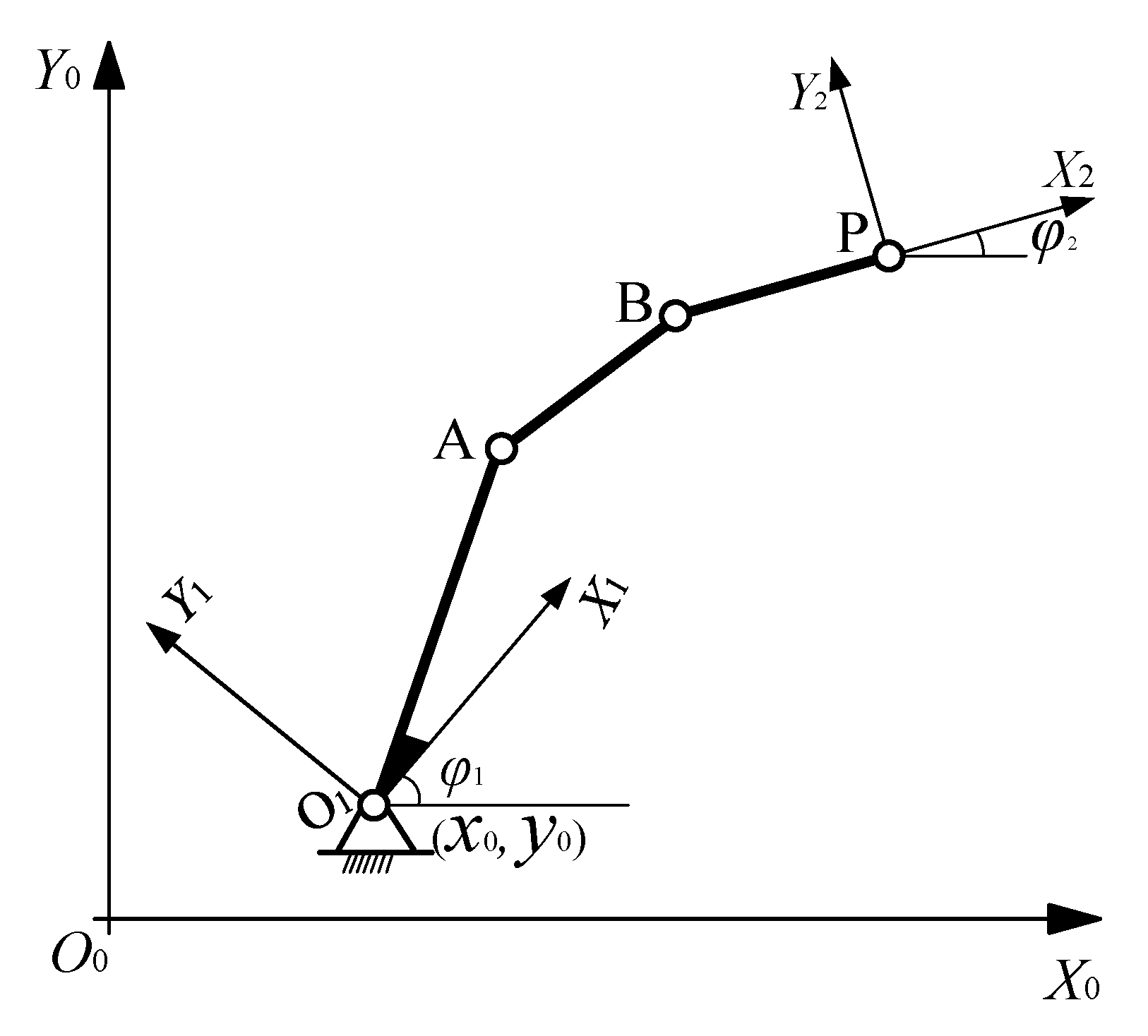
For the rigid-body guidance of the 3R open chain, in addition to the four task poses, the coordinates of the rotation center O 1 of the first bar and the four azimuth angles of the first bar corresponding to the four task poses should also be given. Three coordinate systems are established on the 3R open chain, as shown in Figure 5.
Firstly, the coordinate transformation formula is used to transform the coordinates of four task poses in the fixed coordinate system X 0 O 0 Y 0 to the moving coordinate system X 1 O 1 Y 1 . Secondly, the coordinates of the circle center point (point A) and circle point (point B) of the 2R open chain in the moving coordinate system X 1 O 1 Y 1 are solved according to the above steps of solving the 2R open chain rigid-body guidance with four exact pose constraints. Thirdly, the coordinates of the circle center point (point A) and circle point (point B) of the 2R open chain in the fixed coordinate system X 0 O 0 Y 0 are obtained through coordinate transformation. Finally, the 3R open chain ( O 1 - A - B - P ) can be obtained by connecting the rotation center O 1 with the 2R open chain ( A - B - P ).
A five-bar linkage can be constructed by selecting a group of solutions from the solution regions of the 2R open chain and the 3R open chain, respectively. A pair of gears needs to be fixed on two side links of the five-bar linkage, and the side links need to be fully rotated, that is, the side links are cranks. The solved five-bar linkages should satisfy the bar length conditions of the double crank five-bar linkages [27]: (1) The sum of the lengths of two side links should be less than or equal to the lengths of the other three bars; (2) The sum of the lengths of the two side links and the longest bar should be less than or equal to the sum of the lengths of the other two bars.

2.2.2. Modeling of Noncircular Gears

The relative rotation angles of the two cranks of the five-bar linkages obtained based on kinematic mapping is a finite number of discrete values, and it is necessary to use a cubic non-uniform B-spline curve to fit to obtain the periodic relative rotation angle relationship between the two cranks.
When using cubic non-uniform B-spline curve to fit discrete values, a group of data points x i i = 0 , 1 , 2 , , n must be given first, and then parameterized by a chord length parameterization method [28,29].
The general expression of the B-spline curve equation is:
p u = i = 0 n d i N i , k u
where d i i = 0 , 1 , , n are n + 1 control vertices, and N i , k u is a k t h uniform B-spline base function, which is obtained by substituting the k t h piecewise polynomial determined by the node vector sequence U : u 0 u 1 u 2 u m + k u m + k + 1 into the recurrence formula d e B o o r - C o x , and the recurrence formula N i , k u can be defined as:
N i , 0 u = 1 , u i u u i + 1 0 , other N i , k u = u u i u i + k u   i N i , k 1 u + u i + k + 1 u u i + k + 1 u i + 1 0 0 = 0 N i + 1 , k 1 u
where k is the power of the B-spline. In the formula of the cubic B-spline curve, k = 3 .
When m + 1 data points q i i = 0 , 1 , , m are given, the first and last data points are the first and last points of the B-spline curve, and the generated B-spline curve has n + 1 control vertices d i i = 0 , 1 , , n , where n = m + 2 .
According to the mechanism parameters of the double crank five-bar linkage, the rotation angles of crank O 1 A and crank O 2 C can be calculated when the mechanism passes through four task poses. The absolute rotation angle of crank O 1 A and the relative rotation angle of crank O 2 C are taken as the abscissa and ordinate of the fitting numerical points, and the rotation angle curve in a cycle is determined by five data points q i i = 0 , 1 , , 4 . The abscissa values of q 0 and q 4 differ by 2 π , and the ordinate values are equal. By fitting these five data points, a continuous and smooth curve of two crank angles in a single cycle can be obtained.
Figure 6 is a schematic diagram of the noncircular gear external meshing transmission. The center distance of the noncircular gear pair is a. The rotation center of driving gear is O 1 , the rotation angle is φ 1 and the angular velocity is ω 1 . The rotation center of the driven gear is O 2 , the rotation angle is φ 2 and the angular velocity is ω 2 .
The rotation angle function of the gear pair is:
φ 2 = F ( φ 1 )
The ratio function i 12 of the noncircular gear pair can be expressed as:
i 12 = ω 1 ω 2 = d φ 1 / d t d φ 2 / d t = f ( φ 1 ) f ( φ 1 ) = 1 F ( φ 1 )
In gear transmission, the instantaneous center of velocity is located on the connecting line between the two rotation centers, and ω 1 O 1 G ¯ = ω 2 O 2 G ¯ . Therefore, the instantaneous ratio can be expressed as:
i 12 = ω 1 ω 2 = r 2 r 1 = a r 1 r 1
Therefore, when the center distance and the ratio function are given, the pitch curve equations of the driving gear and the driven gear can be expressed as [30,31]:
r 1 ( φ 1 ) = a 1 + i 12 = a 1 + f ( φ 1 ) r 2 = a r 1 φ 2 = 0 φ 1 1 i 12 d φ 1 = 0 φ 1 r 1 a r 1 d φ 1

3. Results and Discussion

The knee joint is the primary functional component of lower limbs, which plays a role of standing, support during walking and providing power for movement [32]. Therefore, it is of great medical value to study rehabilitation devices related to the knee joint.
Based on the bionic principle and ergonomics, the exoskeleton rehabilitation devices are designed anthropomorphically, so that patients can wear them comfortably. In the existing configuration design of human lower limb exoskeleton rehabilitation devices, the knee joint kinematic model is simply regarded as a rotating pair with the rotation axis perpendicular to the sagittal plane. Although the existing rehabilitation devices have the structural characteristics of a human knee joint, most of them usually only consider the trajectory of the knee joint or the realization of the flexion and extension posture angle, and rarely consider the trajectory and posture at the same time, which is somewhat inadequate in the lower limb rehabilitation devices for correcting patients’ abnormal gaits [33]. In addition, most of these devices have a large number of joints, long kinematic chains and complex structures, which require coordinated control to generate corresponding trajectory curves. In fact, each part of the human body has a fixed movement mode and movement characteristics. Theoretically, the corresponding trajectory and motion law can be realized without too many variables.
This section proposes a knee joint rehabilitation device based on rigid-body guidance of the noncircular gear-five-bar mechanism, which makes the gait trajectory and gait pattern of patients close to that of normal people.

3.1. Acquisition of Knee Joint Motion Data

The distribution of human body size conforms to the normal distribution law; that is, most of them are intermediate values, and only a small part are values that are too large or too small. It is impossible to meet the requirements of all people in the design, but most people must be satisfied. Considering the universality, it is necessary to select the size data that can satisfy the most people from the middle section. According to ergonomics, the percentile is often used as a boundary value for anthropometric data. When collecting knee joint motion data, the subject with the 50th percentile body size is selected for the collection experiment. The 50th percentile represents a medium body size, which means that 50% of the population has a body size above this size, and 50% have a body size below this size. The selected subject is 165 cm in height, 44 cm in thigh length and 39 cm in calf length.
When the subject stands normally, paste the first marker point (upper marker point) on the side of the knee joint of the right leg, and paste the second marker point (lower marker point) at a distance of 20 cm from the first marker point along the calf. The photographer keeps the camera still and approximately perpendicular to the lower limb. During the test, the subject stands upright with her upper body, stands in place with her right leg to simulate a normal gait and cycles multiple gait cycles. Video recording takes place of the whole movement process. Five periods of smooth motion of the subject are selected from the video for post-processing, and the processing flow is shown in Figure 7.
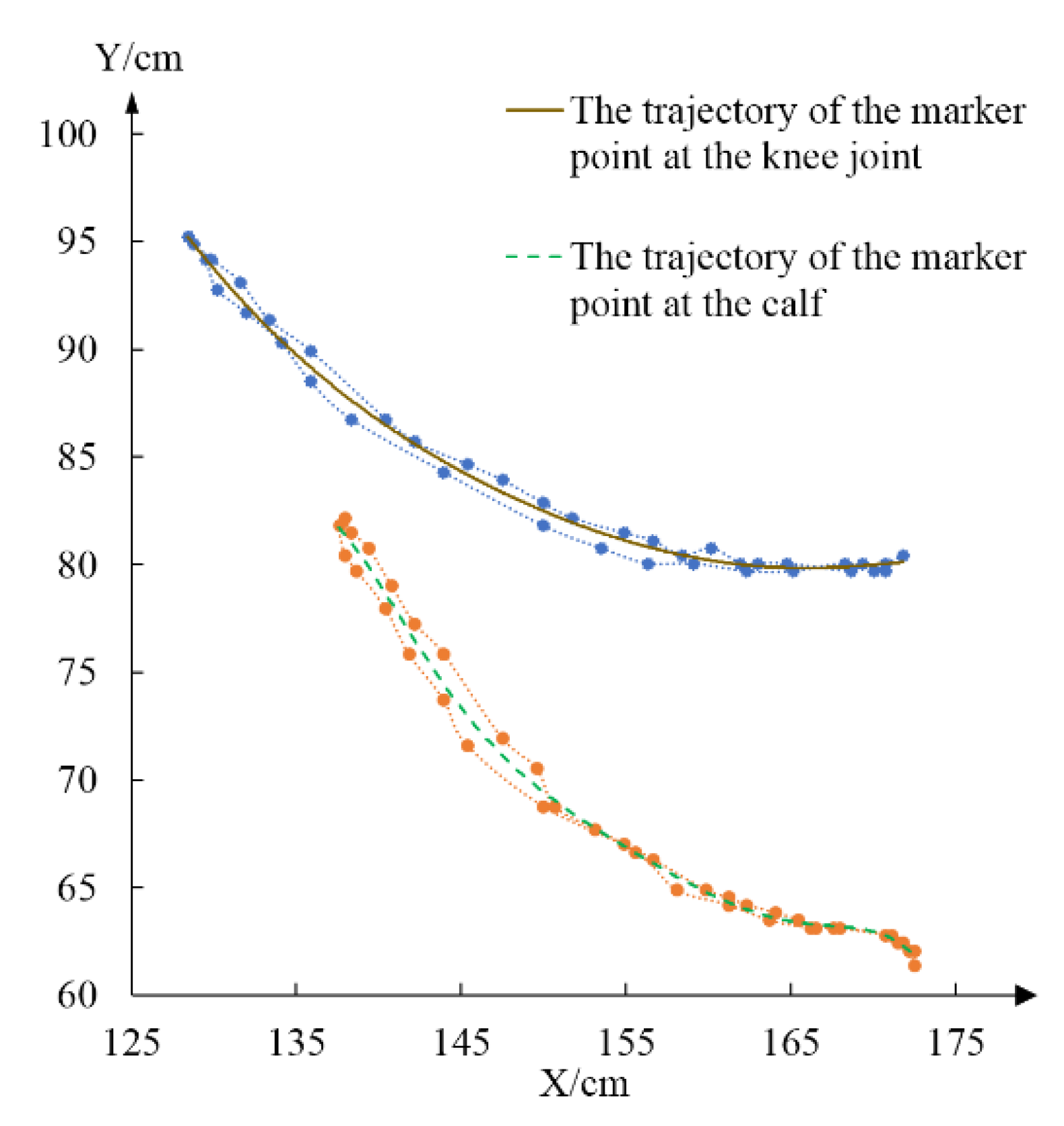
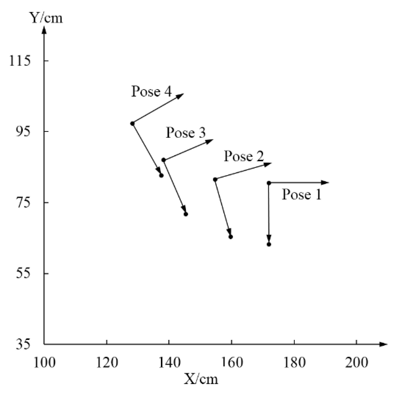
Take the average value of the test data of five cycles and fitting the trajectory curves of the two marker points on the knee joint and the calf, as shown in Figure 8. Then, select the corresponding four groups of key position points from the two curves in Figure 8 to form the four task poses for synthesizing the noncircular gear-five-bar mechanism, as shown in Figure 9. In order to unify with the dimension in the computer-aided software, adjust the relative positions between the coordinate systems and carry out coordinate transformation on the four poses in Figure 9 to obtain the specific values of the four task poses shown in Table 1.

3.2. Synthesis of Noncircular Gear-Five-Bar Mechanism

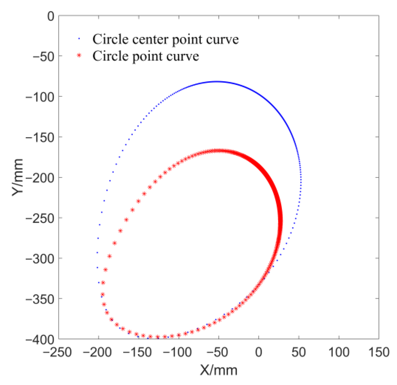
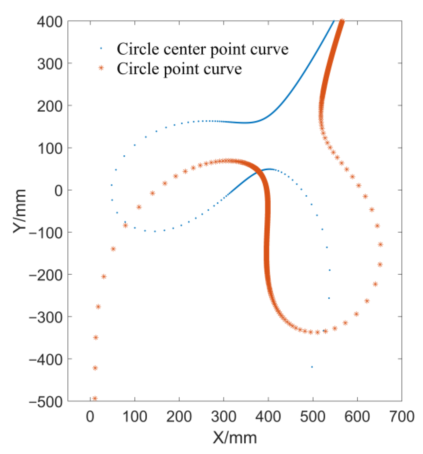
Combined with the movement space of human lower limbs, the bar length range of the double crank five-bar linkage is set to [30, 400] mm, the coordinates of the fixed hinge joint (point O 1 ) of the 3R open chain are (68, 16) mm, and the four azimuth angles of the first bar O 1 A corresponding to the four task poses are (200°, 220°, 250°, 300°). Based on the task poses in Table 1, according to the above-mentioned rigid-body guidance synthesis method of the noncircular gear-five-bar mechanism with four pose constraints, the circle point curve and circle center point curve of the 2R open chain as shown in Figure 10 and the circle point curve and circle center point curve of the 3R open chain as shown in Figure 11 can be obtained, respectively.
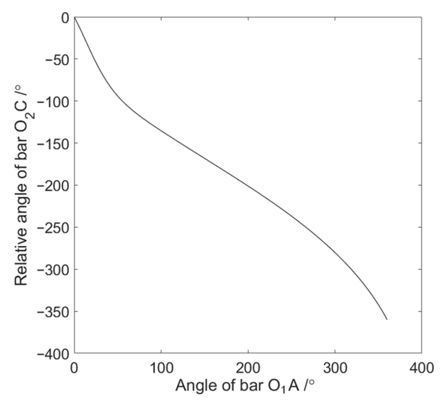
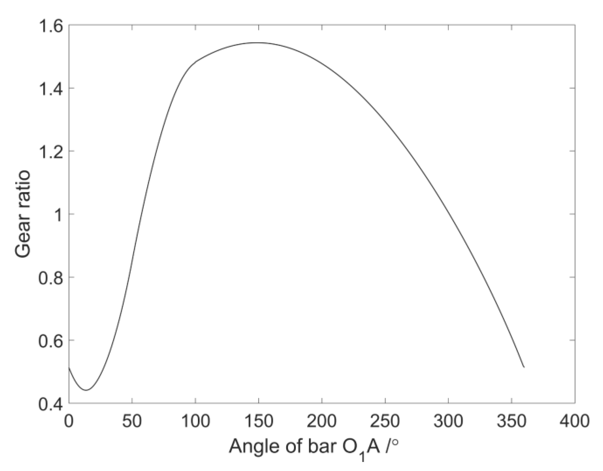
A group of solutions is selected from Figure 10 and Figure 11, respectively, to form a five-bar linkage. The coordinates of the fixed hinge joint (point O 2 ) of five-bar linkage are (−137.16, −120.75). The coordinates of point A are (49.31, −23.96), the coordinates of point B are (18.13, −276.35) and the coordinates of point C are (−69.37, −169.34). The length of each bar of the five-bar linkage can be further obtained: L 1 = 44.11 mm (bar O 1 A ), L 2 = 254.31 mm (bar AB ), L 3 = 138.23 mm (bar BC ), L 4 = 83.41 mm (bar O 2 C ), and L 0 = 246.56 mm (bar O 1 O 2 ). According to the above parameters of the five-bar linkage, the rotation angles of crank O 1 A and crank O 2 C can be calculated when the five-bar linkage passes through four poses. Taking the absolute rotation angle of crank O 1 A and the relative rotation angle of crank O 2 C as the abscissa and ordinate of the fitting numerical points, the relation curve of two crank rotation angles in a single cycle is obtained as shown in Figure 12. According to the calculation model of noncircular gears, the ratio curve of noncircular gears as shown in Figure 13 can be further obtained. Finally, the pitch curves of noncircular gears are calculated according to Equation (19), as shown in Figure 14.
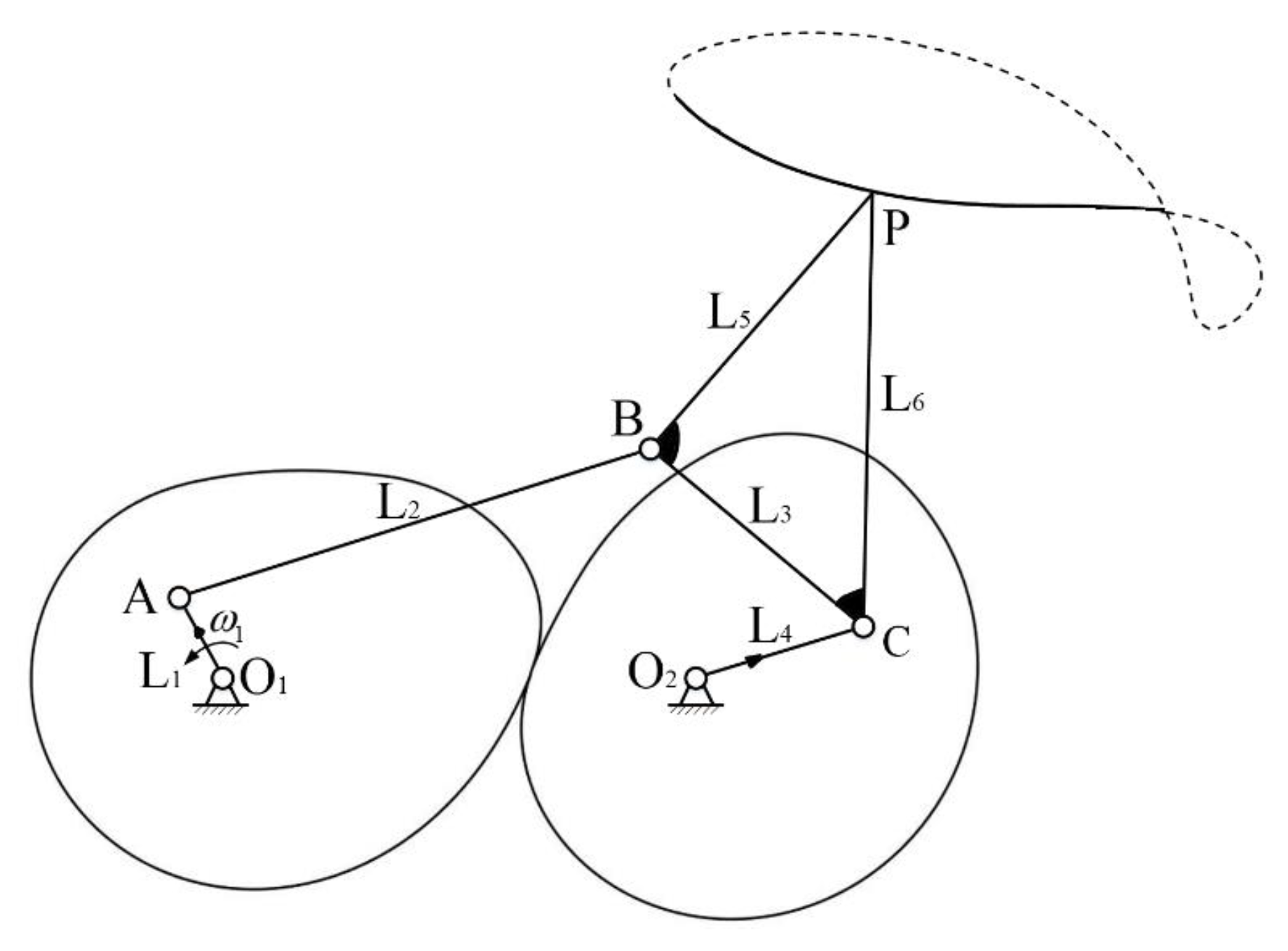
The above five-bar linkage and noncircular gears are combined into a 1-DOF noncircular gear-five-bar mechanism, and its schematic diagram is shown in Figure 15. The motion simulation of the noncircular gear-five-bar mechanism is carried out. It can be seen from Figure 16 that the motion trajectory of point P can accurately pass through the given four task poses, which verifies the correctness of the mechanism synthesis.

3.3. Structural Design and Test of Rehabilitation Device

Figure 17 is a three-dimensional model of the rehabilitation device. In order to further verify the feasibility of the device, a prototype is developed and tested in this paper. The left and right parts of the test bench have the same structure and are symmetrically arranged. The test is carried out with the right leg, as shown in Figure 18. The steps of the test are as follows:
(1)
Place a high-speed camera in a suitable position and adjust the height of the camera to ensure that the camera is perpendicular to the knee joint of the human body.
(2)
The subject stands normally, with the right leg attached to the exoskeleton with a black flexible strap, and the right foot on the pedal. Set an obvious marker point on the knee joint and calf of the subject, and ensure that the end of the noncircular gear-five-bar mechanism (point P) coincides with the marker point of the knee joint.
(3)
Fix the waist of the human body to the back with a black flexible strap.
(4)
The motor controller is used to control the forward and reverse rotation of the motor, and the rotation angle is 78°, so that the right lower limb swings back and forth with the test bench.
(5)
Turn on the high-speed camera to record the movement of the lower limb with the test bench.
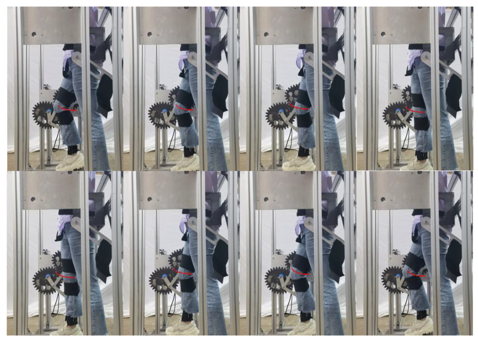
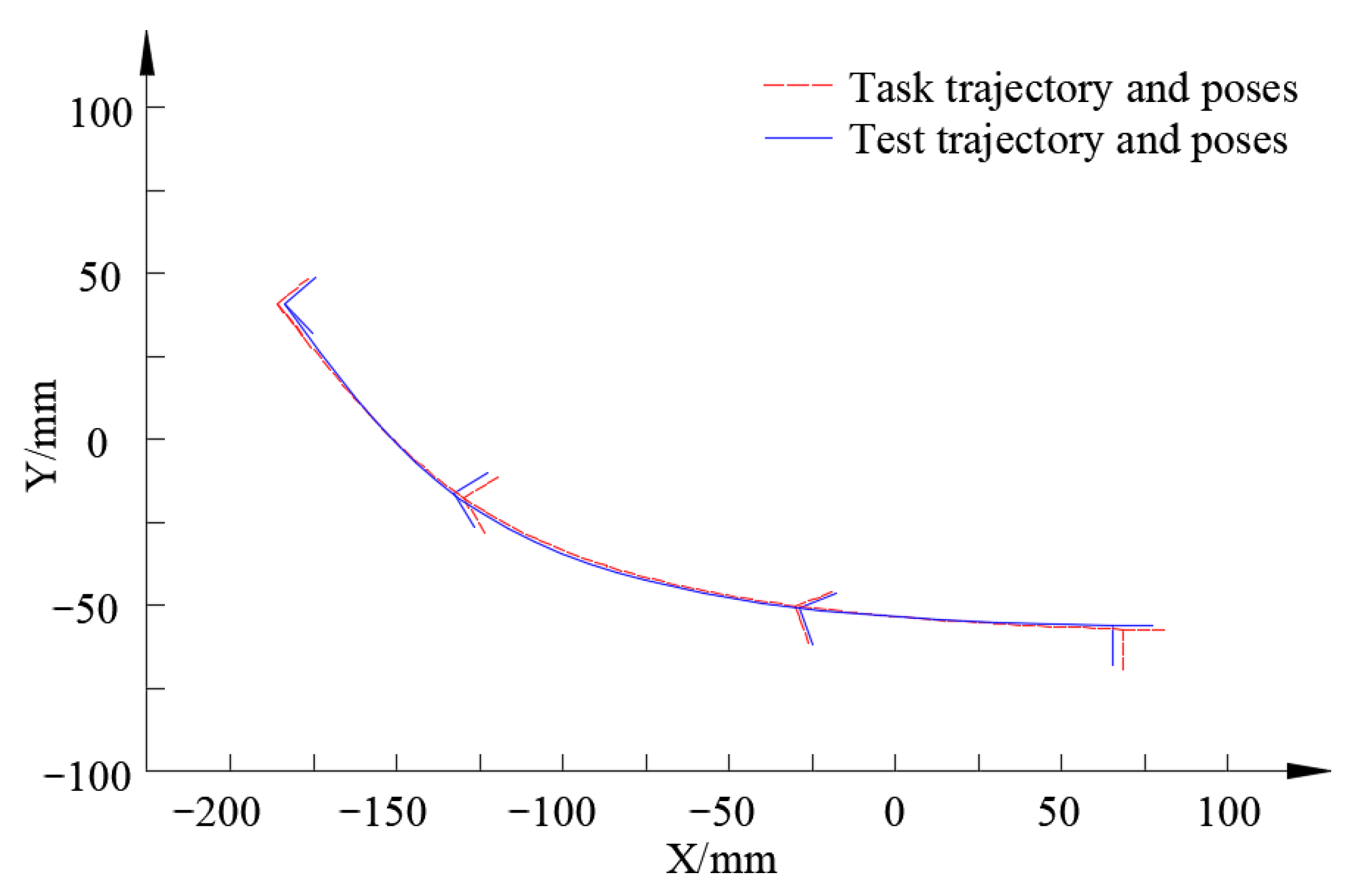
Figure 19 shows the movement state diagram of the lower limb when the knee joint passes through four task poses during the test. Five cycles are selected from the video for processing, and the average value of the data of these five cycles is taken as the test data. The actual motion trajectory and poses can be obtained by processing the data, and comparing with the task trajectory and poses, as shown in Figure 20.
Figure 20 shows that the actual test trajectory of the prototype is almost consistent with the task trajectory, and the knee joint can pass through the given four task poses in sequence, but there is still a small error. Table 2 shows the comparison between the theoretical and actual values of the positions and postures at the marker point of the knee joint during the test. It can be seen from Table 2 that the maximum error between the actual position and task position at the marker point of the knee joint is 3.32 mm, and the maximum error between the actual posture angle and task posture angle is 2.13°. In the range of allowable error, the design and development of the knee joint rehabilitation device based on rigid-body guidance of the noncircular gear-five-bar mechanism is correct and reliable.

3.4. Discussion

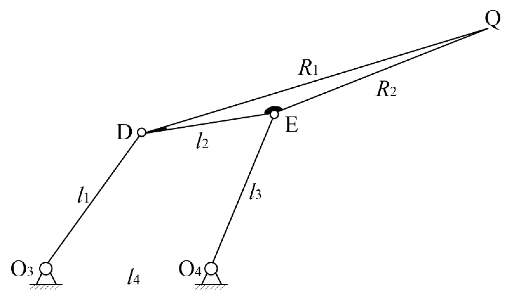
For the four task poses in Table 1, a four-bar linkage with a simple structure is considered first. Based on the kinematic mapping theory, the rigid-body guidance synthesis software of four-bar linkage with four pose constraints is compiled, and the same initial conditions and constraints as the noncircular gear-five-bar mechanism are substituted. By eliminating the mechanisms with branch defects, sequence defects and loop defects, multiple groups of four-bar linkage solutions can be obtained. Figure 21 shows a group of solutions with better configuration among all four-bar linkages. The specific bar lengths are as follows: l 1 = 118.079   mm , l 2 = 97.5941   mm , l 3 = 120.838   mm , l 4 = 118.866   mm , R 1 = 260.337   mm and R 2 = 164.58   mm . It can be seen from Figure 21 that the size of the actuator DEQ is too large, the configuration is unreasonable and the stability is poor.
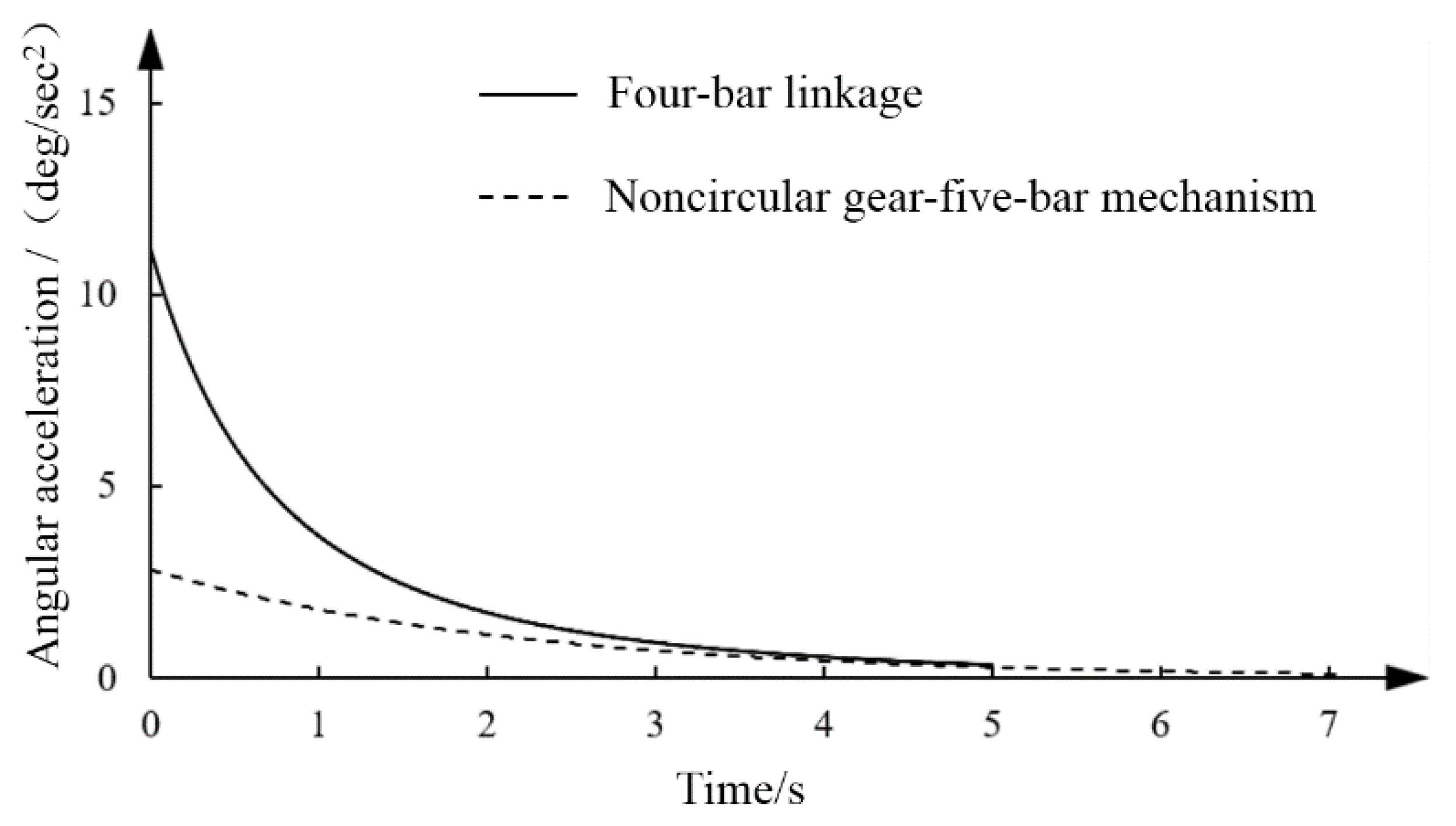
The walking speed of patients with limb disorders is slow, and the movement stability is necessary for the lower limb exoskeleton rehabilitation device, which can avoid secondary injury to the human body [34]. The motion simulation analysis of planar four-bar linkage and the noncircular gear-five-bar mechanism is carried out, and the same drive is added to obtain the angular acceleration diagram of the actuators of two mechanisms, as shown in Figure 22. It can be seen from Figure 22 that the angular acceleration curve of the actuator of the noncircular gear-five-bar mechanism is smoother and the movement is more stable.
In conclusion, given the same initial conditions and constraints of rigid-body guidance, the noncircular gear-five-bar mechanism has more reasonable configuration and better kinematic characteristics than the four-bar linkage.

4. Conclusions

(1)
In this paper, the research object of rigid-body guidance synthesis is extended to the noncircular gear-five-bar combined mechanism. The noncircular gear-five-bar mechanism is regarded as the combination of a 2R open chain, a 3R open chain and a pair of noncircular gears, and a rigid-body guidance synthesis method of the noncircular gear-five-bar mechanism based on kinematic mapping is proposed.
(2)
Based on the four exact task poses required for knee joint rehabilitation, a noncircular gear-five-bar mechanism is synthesized and applied to exoskeleton knee joint rehabilitation. The structure design, prototype development and tests of the rehabilitation device are carried out. The test results show that the device can drive the lower limb for rehabilitation training, and the knee joint can pass through the given four task poses, which verifies the correctness of the proposed rigid-body guidance synthesis method.

Author Contributions

Conceptualization, C.Y. and J.C.; Methodology, C.Y.; Software, Y.Z.; Validation, K.Y., Y.Z. and J.Y.; Formal Analysis, Y.Z.; Investigation, J.Y.; Resources, J.C.; Data Curation, K.Y.; Writing—Original Draft Preparation, Y.Z.; Writing—Review & Editing, C.Y., K.Y., J.Y. and J.C.; Visualization, K.Y.; Supervision, C.Y.; Project Administration, J.C.; Funding Acquisition, J.Y. and J.C. All authors have read and agreed to the published version of the manuscript.

Funding

This research was funded by the National Natural Science Foundation of China [grant number 51975536] and the Zhejiang Provincial Natural Science Foundation of China [grant number LQ20E050003].

Data Availability Statement

The data presented in this study are available on request from the corresponding author.

Conflicts of Interest

The authors declare no conflict of interest.

References

  1. Burmester, L. Lehrbuch der Kinematik; Verlag Von Arthur Felix: Leipzig, Germany, 1888. [Google Scholar]
  2. Han, J.Y.; Qian, W.X. On the solution of region-based planar four-bar motion generation. Mech. Mach. Theory. 2009, 44, 457–465. [Google Scholar] [CrossRef]
  3. Deshpande, S.; Purwar, A. A task-driven approach to optimal synthesis of planar four-bar linkages for extended Burmester problem. J. Mech. Robot. 2017, 9, 061005. [Google Scholar] [CrossRef] [Green Version]
  4. Ge, Q.J.; Zhao, P.; Purwar, A.; Li, X.Y. A novel approach to algebraic fitting of a pencil of quadrics for planar 4R motion synthesis. J. Comput. Inf. Sci. Eng. 2012, 12, 041003. [Google Scholar] [CrossRef]
  5. Ge, Q.J.; Purwar, A.; Zhao, P.; Deshpande, S. A task-driven approach to unified synthesis of planar four-bar linkages using algebraic fitting of a pencil of G-manifolds. J. Comput. Inf. Sci. Eng. 2017, 17, 031011. [Google Scholar] [CrossRef] [Green Version]
  6. Qian, W.X.; Han, J.Y. Solution region analysis and synthesis method of 4-position rigid-body guidance. Chin. J. Eng. 2008, 30, 1163–1168. [Google Scholar]
  7. Han, J.Y.; Cai, Y.J. Solution-region synthesis method of single-degree-of-freedom planar six-bar mechanisms for robotic fingers. Trans. Chin. Soc. Agric. Mach. 2018, 49, 367–373. [Google Scholar]
  8. Cui, G.Z.; Han, J.Y.; Yang, T. The synthesis method of eight-bar linkage based on solution region synthesis theory. J. Northeastern. Univ. (Nat. Sci.) 2015, 36, 1010–1014. [Google Scholar]
  9. Shao, Y.X.; Xiang, Z.X.; Liu, H.T.; Li, L.L. Conceptual design and dimensional synthesis of cam-linkage mechanisms for gait rehabilitation. Mech. Mach. Theory 2016, 104, 31–42. [Google Scholar] [CrossRef]
  10. Sun, Y.X.; Ge, W.J.; Zheng, J.; Dong, D.B. Design and evaluation of a prosthetic knee joint using the geared five-bar mechanism. IEEE Trans. Neural. Syst. Rehabil. Eng. 2015, 23, 1031–1038. [Google Scholar] [CrossRef]
  11. Modler, K.H.; Lovasz, E.C.; Bär, G.F.F.; Neumann, R. General method for the synthesis of geared linkages with non-circular gears. Mech. Mach. Theory 2009, 44, 726–738. [Google Scholar] [CrossRef]
  12. Mundo, D.; Gatti, G.; Dooner, D.B. Optimized five-bar linkages with non-circular gears for exact path generation. Mech. Mach. Theory 2009, 44, 751–760. [Google Scholar] [CrossRef]
  13. Shih, A.J.; Yan, H.S. Synthesis of a single-loop overconstrained six revolute joint spatial mechanism for two-position cylindrical rigid body guidance. Mech. Mach. Theory 2002, 37, 61–73. [Google Scholar] [CrossRef]
  14. Shirazi, K.H. Synthesis of an 8S5R mechanism in four-point rigid body guidance problem using Maple. Mech. Mach. Theory 2008, 43, 285–296. [Google Scholar] [CrossRef]
  15. Sun, J.W.; Wang, P.; Liu, W.R.; Chu, J.K. Wavelet characteristic parameter method of a planar four-bar mechanism motion generation synthesis. Chin. Mech. Eng. 2018, 29, 688–695. [Google Scholar]
  16. Sun, J.W.; Liu, Q.; Chu, J.K. Motion generation of RCCC mechanism using numerical atlas. Mech. Based Des. Struc. Mach. 2017, 45, 62–75. [Google Scholar] [CrossRef]
  17. Chung, W.Y. Synthesis and analysis of spatial CS-3SS mechanism for body guidance. Proc. Inst. Mech. Eng. Part C-J. Mech. Eng. Sci. 2015, 229, 2455–2466. [Google Scholar] [CrossRef]
  18. Zhao, P.; Li, X.Y.; Zhu, L.H.; Zi, B. A novel motion synthesis approach with expandable solution space for planar linkages based on kinematic-mapping. Mech. Mach. Theory 2016, 105, 164–175. [Google Scholar] [CrossRef]
  19. Zhao, P.; Wang, Y.; Zhu, L.H.; Li, X.Y. A frame-independent comparison metric for discrete motion sequences. Proc. Inst. Mech. Eng. Part C-J. Mech. Eng. Sci. 2020, 234, 1764–1774. [Google Scholar] [CrossRef]
  20. Cui, G.Z.; Han, J.Y. The solution region-based synthesis methodology for a 1-DOF eight-bar linkage. Mech. Mach. Theory 2016, 98, 231–241. [Google Scholar] [CrossRef]
  21. Ravani, B.; Roth, B. Motion synthesis using kinematic mappings. ASME J. Mech. Transm. Autom. Des. 1983, 105, 460–467. [Google Scholar] [CrossRef]
  22. Li, X.Y.; Ge, X.; Purwar, A.; Ge, Q.J. A unified algorithm for analysis and simulation of planar four-bar motions defined with R- and P-joints. J. Mech. Robot. 2015, 7, 011014. [Google Scholar] [CrossRef]
  23. Purwar, A.; Deshpande, S.; Ge, Q.J. MotionGen: Interactive design and editing of planar four-bar motions for generating pose and geometric constraints. J. Mech. Robot. 2017, 9, 024504. [Google Scholar] [CrossRef]
  24. Zhao, P.; Li, X.Y.; Purwar, A.; Ge, Q.J. A task-driven unified synthesis of planar four-bar and six-bar linkages with R- and P-joints for five-position realization. J. Mech. Robot. 2016, 8, 061003. [Google Scholar] [CrossRef]
  25. Zhao, P.; Ge, X.; Zi, B.; Ge, Q.J. Planar linkage synthesis for mixed exact and approximated motion realization via kinematic mapping. J. Mech. Robot. 2016, 8, 051004. [Google Scholar] [CrossRef]
  26. Yu, C.N.; Ye, J.; Jia, J.M.; Zhao, X.; Chen, J.N. Design, synthesis, and experiment of foot-driven lower limb rehabilitation mechanisms. J. Mech. Robot. 2022, 14, 021001. [Google Scholar] [CrossRef]
  27. Liao, H.Y.; Kong, J.Y.; Li, J.; Tang, B. The types of 5-bar linkage with two-degree of freedom and their differentiation. J. Hubei Univ. Technol. 2006, 21, 4–6. [Google Scholar]
  28. Mao, Z.Y.; Liu, Z.J. A trajectory planning method for cubic uniform B-spline curve. Chin. Mech. Eng. 2010, 21, 2569–2572. [Google Scholar]
  29. Wang, F. Quasi-cubic B-spline curve and its application. Adv. Appl. Math. 2020, 9, 1255–1262. [Google Scholar] [CrossRef]
  30. Huang, Z.C.; Lan, Z.H. Design of transmission ratio function of non-circular gears with closed pitch curve. J. Mech. Trans. 2011, 35, 30–33. [Google Scholar]
  31. Sun, L.; Wang, Z.F.; Wu, C.Y.; Zhang, G.F. Novel approach for planetary gear train dimensional synthesis through kinematic mapping. Proc. Inst. Mech. Eng. Part C-J. Mech. Eng. Sci. 2019, 234, 273–288. [Google Scholar] [CrossRef]
  32. Irawan, A.P.; Halim, A.; Kurniawan, H. Hybrid robot climbing system design. IOP Conf. Ser Mater. Sci. Eng. 2017, 237, 012006. [Google Scholar] [CrossRef]
  33. Li, J.F.; Huang, X.Q.; Tao, C.J.; Wang, S.; Ji, R. Configuration synthesis and structure design of knee rehabilitation exoskeleton. J. Harbin Eng. Univ. 2017, 38, 625–632. [Google Scholar]
  34. Li, S. Design and Research of a Wearable Lower Limb Rehabilitation Robot. Master’s Thesis, Yanshan University, Qinhuangdao, China, 2021. [Google Scholar]
Figure 1. Diagram of kinematic mapping.
Machines 10 01110 g001
Figure 2. Coordinate system of rigid-body motion.
Machines 10 01110 g002
Figure 3. Schematic diagram for generating noncircular gear-five-bar mechanism.
Machines 10 01110 g003
Figure 4. Design flow chart of noncircular gear-five-bar mechanism with four pose constraints.
Machines 10 01110 g004
Figure 5. Establishment of coordinate systems of 3R open chain.
Machines 10 01110 g005
Figure 6. Schematic diagram of noncircular gear external meshing transmission.
Machines 10 01110 g006
Figure 7. Video processing flow.
Machines 10 01110 g007
Figure 8. The trajectories of two marker points.
Machines 10 01110 g008
Figure 9. Four task poses.
Machines 10 01110 g009
Figure 10. Circle center point curve and circle point curve of the 2R open chain.
Machines 10 01110 g010
Figure 11. Circle center point curve and circle point curve of the 3R open chain.
Machines 10 01110 g011
Figure 12. The relation curve of two crank rotation angles in one cycle.
Machines 10 01110 g012
Figure 13. The ratio curve of noncircular gears.
Machines 10 01110 g013
Figure 14. The pitch curves of noncircular gears.
Machines 10 01110 g014
Figure 15. Diagram of noncircular gear-five-bar mechanism.
Machines 10 01110 g015
Figure 16. Verification of simulation results.
Machines 10 01110 g016
Figure 17. 3D model of the exoskeleton knee joint rehabilitation device.
Machines 10 01110 g017
Figure 18. Layout of test bench.
Machines 10 01110 g018
Figure 19. The movement state diagram of the lower limb when the knee joint passes through four task poses.
Machines 10 01110 g019
Figure 20. Comparison between test trajectory and poses and task trajectory and poses.
Machines 10 01110 g020
Figure 21. Diagram of four-bar linkage.
Machines 10 01110 g021
Figure 22. Comparison of angular acceleration between four-bar linkage and noncircular gear-five-bar mechanism.
Machines 10 01110 g022
Table 1. The specific values of four task poses.
NumberX-Coordinate
(mm)
Y-Coordinate
(mm)
Posture
(°)
168.70−57.220
2−30.15−50.1020
3−129.82−17.7131
4−185.8340.8440
Table 2. Comparison between the theoretical and actual values of the positions and postures at the marker point of the knee joint.
NumberTheoretical Coordinates
(mm)
Actual Coordinates
(mm)
Position Error
(mm)
Theoretical Posture Angle
(°)
Actual Posture Angle
(°)
Angle Error
(°)
1(68.70, −57.22)(66.41, −55.87)2.6600.070.07
2(−30.15, −50.10)(−29.00, −50.81)1.352021.161.16
3(−129.82, −17.71)(−132.88, −16.43)3.323131.980.98
4(−185.83, 40.84)(−183.45, 40.75)2.384042.132.13
Publisher’s Note: MDPI stays neutral with regard to jurisdictional claims in published maps and institutional affiliations.