Article

Multi-Disciplinary Analysis of Working Fluids on Thermal Performance of the High-Power Diesel Engine System

Department of Automotive Engineering, Tongmyong University, Busan 48520, Korea
Machines 2022, 10(11), 1023; https://doi.org/10.3390/machines10111023
Submission received: 20 August 2022 / Revised: 25 October 2022 / Accepted: 1 November 2022 / Published: 3 November 2022
(This article belongs to the Special Issue Heat Transfer and Energy Harvesting in Fluid System)

Abstract

:
Multi-disciplinary analysis was performed to analyze and investigate the thermal performance during transient operation of a 2 L diesel engine system with two different cooling systems. The multi-disciplinary model consisted of the engine thermal management system (ETMS) comprising a zero-dimensional engine model that can simulate the engine performance, and a one-dimensional flow model for cooling and lubrication systems with a controller. By deploying this approach, we were able to model different physical domains, including mechanical for the engine and the dynamometer and thermodynamic for the heat exchangers. Therefore, the thermal performance of the ETMS could be numerically predicted and analyzed. To develop the ETMS model, the physical properties, the heat transfer model, and the pressure drop were modeled. The base fluid, a 50/50 mixture of water and ethylene glycol (EG), and an Al2O3 nanofluid with a 1.5% volume ratio were modeled based on the thermodynamic properties such as density, dynamic viscosity, thermal conductivity, and specific heat. Nanofluid, with its higher thermal conductivity and higher heat transfer coefficient, absorbed more heat from the combustion chamber through the water-jacket in the engine block. Therefore, the oil temperature for the nanofluid was effectively 2.5 °C less than for the base fluid following the step-load condition. Simulation results showed the better effect of nanofluid on thermal performance. The total flow rate of nanofluid decreased by 2.2 L/min, although the flow rate through the radiator with nanofluid increased by 0.81 L/min to obtain greater heat dissipation. Eventually, the piston and the liner temperatures with the nanofluid were drastically reduced by 7.55 and 8 °C, respectively, compared to those of the base fluid. Finally, when nanofluids was applied in automotive cooling systems, the temperature of the piston decreased by 7.3 °C due to the reduced overall thermal resistance from combustion chambers to outside air. The effect of working fluid on the diesel engine system could be predicted through the multi-disciplinary model.

1. Introduction

To comply with global environmental regulations, diesel engines are becoming more efficient. To obtain higher fuel efficiency for a diesel engine, it is necessary to optimize the engine and improve the overall engine thermal system. In recent years, the technology to reduce heat generation from the combustion chambers by increasing combustion efficiency of diesel engines or to use the wasted heat to warm vehicles has been widely developed [1,2]. Many studies are underway to develop ways to control and manage the overall thermal system of diesel engines actively and accurately. Most of these technologies have focused on high-efficiency heat exchangers and system control technology [3,4]. During the last few decades, the specific power of diesel engines rapidly increased to meet customer’s demands and global regulations. Generally, the engine uses a base fluid as a 50/50 mixture of water and ethylene glycol (EG), which lowers the freezing point or elevates the boiling point of a liquid. The thermal–fluid properties of the base fluids have limits in reducing the size of the cooling system with various heat exchangers. Therefore, the need for new cooling fluid with better thermal properties than conventional coolant is required with the development of highly efficient and compact heat exchangers. Nanofluids are made by dispersing nanoparticles in base fluids, which creates better heat transfer performance, characterized by conductivity and convective heat transfer coefficients, compared to the ordinary coolant, as shown in Figure 1 [5]. Nanoparticles are the main determinant of thermal conductivity performance of nanofluids. In general, a variety of 100 nm-sized nanoparticles, such as metal nanoparticles and ceramic-based nanoparticles, are used to improve the manufacture and heat transfer performance of nanofluids. Currently, various nanoparticles have been used in nanofluid applications. The cooling performance of the engine can be improved by the nanofluids with better heat transfer performance compared to the EG-based fluid in the engine. As the overall size of the cooling system can be reduced, this can be expected to eventually improve fuel economy [5,6,7]. It also increases the reliability of the diesel engine system due to the lower peak temperature in the engine system.
Since the first introduction of nanofluids by Choi [8] during the 1990s, many researchers have mainly focused on the measurement of nanofluid thermal properties such as specific heat, heat conductivity, and dynamic viscosity. In the early 2000s, nanofluids began to be applied in the industry to electronic cooling systems, nuclear reactors, and building heating and cooling systems [9]. Choi et al. [10] measured the heat transfer coefficient of EG-based metallic and oxide nanofluids using a hot-transient–hot-wire method. As a result, heat dissipation was improved for the radiator of a vehicle. An application study on an engine cooling system was initiated by Tzeng et al. [11]. They investigated improvement in heat transfer performance by applying CuO and Al2O3 nanofluids as automatic transmission fluid (ATF). The improvement of cooling performance by two nanofluids was compared under conditions of 400, 800, 1200, and 1600 rpm for a four-wheel drive (4WD) power train. Among of them, CuO nanofluid showed better cooling performance at all rotational speeds. Zhang et al. [12] conducted experiments to determine the effect of nanographite nanofluids on the cooling performance of a heavy-duty diesel engine. The cooling performance of nanofluid with 3 vol% nanographite increased by 15% compared to the base fluid. Saripell et al. [13] studied the cooling performance of a truck engine. Using 2% and 4% CuO nanofluids, they analyzed the engine temperature according to the pump speed and engine power. Nanofluids could reduce the pump speed to 50% to release the same amount of heat in the radiator. Eventually, it reduced the fuel consumption of the truck. Yli et al. [14] studied the effect of Al2O3 nanofluid on the cooling performance of a radiator. The optimal heat transfer performance was obtained for 1% volume fraction of nanofluids. Further volume fraction increases were shown to degrade the cooling performance of the cooling system’s radiator. Esfe et al. [15] proposed new ANN modeling of thermal properties of EG-based hybrid nanofluid containing ZnO-DWCNT nanoparticles for internal combustion engine applications. Thermal conductivity of EG-based hybrid nanofluid was investigated experimentally at ZnO particle concentrations ranging from 0.045 to 1.9% and temperatures of 30–50 °C. Balitskii et al. [16] performed theoretical and experimental studies of nanofluids and devices made of nanoparticles of various weights in a cylinder-head cooling system. Erkan et al. [17] investigated the effects of Al2O3, SiO2, and TiO2 in nanofluid on the engine thermal performance of a four-stroke internal combustion engine radiator. The lowest exhaust temperature was measured when an Al2O3/ethylene glycol mixture was used, which resulted in a 59 K difference.
Recently, many researchers have investigated numerically the effect of nanofluid on the cooling performance for vehicle engine cooling systems. Vajjha et al. [18] conducted a numerical analysis of fluid dynamics and heat transfer performance for Al2O3 and CuO nanofluids in the flat tubes of a radiator. At a Reynolds number of 2000, the average heat transfer coefficient for a 10% Al2O3 nanofluid increased by 94%, and for a 6% CuO nanofluid, 89%. The average skin friction coefficient for a 6% CuO nanofluid in the fully developed region is about 2.75 times compared to that for the base fluid. Huminic and Huminic [19] performed a three-dimensional analysis for the cooling performance of copper–ethylene glycol nanofluid through the flat tubes of an automobile radiator. The maximum heat transfer coefficient increased by 82% at a Reynolds number of 125. Abbasi and Baniamerian [20] introduced an analytical study of fluid flow for the in-tube stratified regime of two-phase nanofluid for CuO, Al2O2, TiO3 and Au as applied nanoparticles in water as the base fluid. Delavari and Hashemabadi [21] simulated turbulent and laminar flow heat transfer in Al2O3 nanofluids passing through a flat tube in three-dimensions by using computational fluid dynamics (CFD) for single- and two-phase approaches. A small difference in the friction of the tubes was observed for the two approaches, and less pumping power was predicted for the nanofluids due to less volumetric flow for the same heat rejection.
Most previous studies mainly focused on the heat transfer performance for a single tube or a heat exchanger, which is one component within the engine cooling system; there has been limited research on the whole system, where there are many heat exchangers and tubes interacting in the heat exchange. A comprehensive and systematic analysis of the whole engine cooling system is needed for designing the engine thermal management system (ETMS). In this study, the effect of working fluids such as base fluid and nanofluid on the thermal management performance of a diesel engine was analyzed by a multi-disciplinary model. It used a new working fluid concept design in the whole power train with various subsystems and components, together with virtual component integration. By deploying this approach, we were able to model different physical domains, including mechanical for the engine and the dynamometer and thermodynamics for the heat exchangers. The thermal performance of the ETMS could be numerically predicted and analyzed, which was hard to investigate by experiments. The ETMS models for base fluid and Al2O3 nanofluid were developed for a 2L high-power diesel engine. The thermal performance of components such as the coolant, oil, and piston and liner were investigated during engine operating modes consisting of engine idling, step-load for the uphill condition, and re-idling.

2. Methodology

2.1. Multi-Disciplinary Model of the Diesel Engine

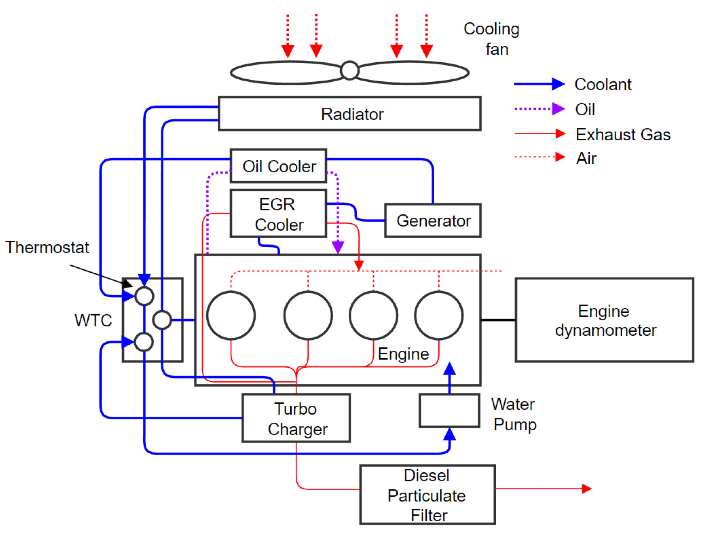
The commercial code of CRUISE M multi-disciplinary software was used to model and analyze the vehicle thermal management system for a diesel engine and its cooling system. It enables provision for the transfer of heat generated in the cylinder through the engine block, air coolant, and oil circuit to dedicated heat exchangers such as a radiator and oil cooler, etc. [22]. The engine thermal management model consists of a zero-dimensional engine model that can simulate engine performance and a one-dimensional flow model for cooling and lubrication systems with the controller. Figure 2 shows a schematic diagram of the cooling system for the diesel engine, which includes various cooling circuits such as the heat exchangers, pump, and tubes.
As shown in Figure 2, the heat generated by the combustion chamber is transferred to the engine coolant and engine oil through the interior wall of the combustion chamber. Heat transfer from turbocharger passes through the exhaust gases. The heat in the coolant and oil are exchanged through the engine oil cooler. The heat of exhaust gas is transferred to the coolant through the exhaust gas recirculation (EGR) cooler. The coolant flow rate through the inside of the radiator is determined by the thermostat, and the engine coolant temperature is controlled by the heat transfer between the radiator and the cooling air. The engine could be effectively warmed and cooled faster through the engine thermal management system (ETMS).
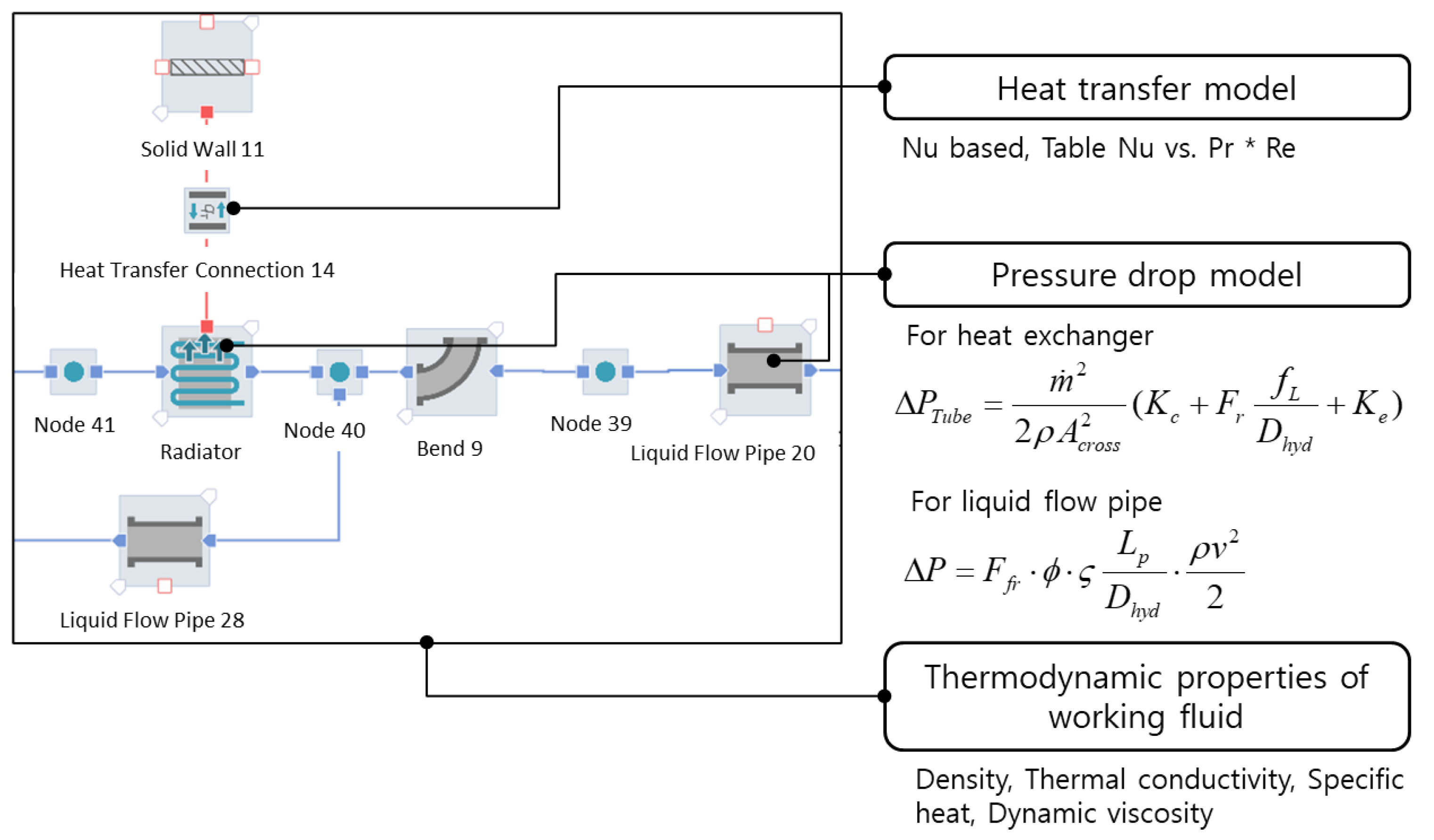
The engine thermal management system is modeled based on the engine model, including the engine block, the cooling system and lubricant system model, the radiator air path model, and the engine controller, as shown in Figure 3. The engine dynamometer is also included in the ETMS and considers the actual operating conditions. The ETMS model numerically predicts the heat generated from the combustion chamber under the engine’s operating condition and describes the heat transfer from the cooling system to the external air. To build the ETMS model, the physical properties, the heat transfer model, and the pressure-drop model are required, as shown in Figure 4. In this study, the working fluids are modeled by using the thermodynamic properties of Al2O3 nanofluid with a 1.5% volume ratio.

2.2. Modeling of the Properties of the Working Fluids

Modeling nanofluid properties provide for fluid dynamic properties such as the density and dynamic viscosity, and thermal properties such as conductivity, specific heat, and thermal expansion. Generally, compared to base fluids, nanofluids are reported to have large density, dynamic viscosity, and thermal coefficient, and low specific heat [8,9,10]. To simplify the model in the multi-disciplinary analysis, the thermal expansion of the working fluid is not considered in the ETMS [22]. The properties of nanofluids determine the thermal-flow characteristics of the engine, which is the primary factor determining the engine heat management. Therefore, it is necessary to develop an accurate model for the material properties to analyze the thermal performance of nanofluid cooling systems. The engine coolant has a wide operating temperature range from the initial warming to cooling. Although the temperature is maintained near 80 °C at the engine outlet, the coolant temperature inside an engine water jacket that directly absorbs heat from the engine can be very high. Thus, to simulate the whole ETMS, the thermodynamic properties of the base fluid and nanofluid should be modeled as full operating conditions ranging from −10 °C to 140 °C. The properties are modeled according to the temperature based on the value of a 50/50 mixture of water and EG, as provided in reference [22]. Thermodynamic properties depend greatly on nanoparticles. In this study, Al2O3 nanoparticles are employed and the physical properties of Al2O3 are summarized in Table 1 [23].

2.2.1. Density

Density is proportional to the volume ratio of the nanofluid in the system due to the higher density of the nanofluid compared to that of the base fluid. The model of thermofluid properties of nanofluids can be developed using theoretical and experimental models [5,7,9]. Sommers and Yerkes [24] measured the density of Al2O3–propanol nanofluid at room temperature. However, there are a few limited works that measured Al2O3 for various volume fractions. In addition, the density of the nanofluids has been known to be consistent with the mixing rule. The mixing rule, a commonly used theoretical formula, follows [25]:
ρ n f = m n f V n f = ρ b f V b f + ρ p V p V b f + V p = ( 1 φ ) ρ b f + φ ρ p
where m n f is the mass of nanofluid, V n f is the volume of nanofluid, V b f is the volume of base fluid, V p is the volume of the nanoparticle, ρ b f is the density of base fluid, and ρ p is the nanoparticle density. The volume fraction of nanofluid is defined as φ = V p   / ( V p + V b f ) .
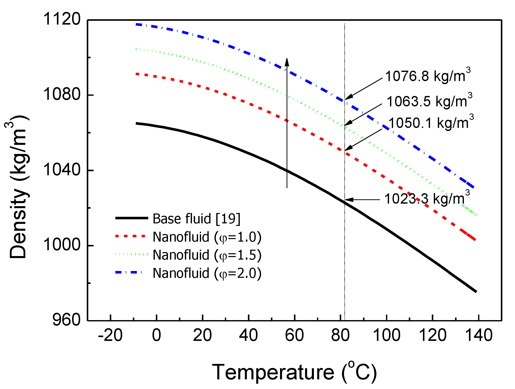
Figure 5 shows the density of the base fluid and the nanofluid for the temperature and the volume fraction. The density curve of the base fluid is from reference [22]. Then, the density variations in the working fluid and the volume fraction are calculated from the mixing rule (Equation (1)). Since the temperature increases, the density of base fluids decreases, as shown in Figure 5. As the volume fraction of the nanofluid increases at a given temperature, the density of the nanofluid also increases. At 81 °C, the density of Al2O3 nanofluid with a 1.5% volume fraction increases by 3.92% compared to that of the base fluid.

2.2.2. Dynamic Viscosity

Dynamic viscosity is the resistance of a fluid to a movement and is known as the main factor determining the loss of pumping power for the cooling system. Generally, it is mainly affected by temperature changes, as shown in Figure 6. Dynamic viscosity of nanofluids depends on the nanoparticle size, shape, and concentration, the potential of hydrogen (pH) in the solution, the surfactant concentration, and the dispersion temperature of the nanoparticles [5,7]. Dynamic viscosity is modeled by Einstein’s model, which is validated in the range φ 0.02 and represented by a linear increase in dynamic viscosity with particle volume fraction. Einstein’s model can be expressed as follows [26]:
μ r = μ n f μ b f = ( 1 + 2.5 φ )
where μ n f is the dynamic viscosity of nanofluid, μ b f is the dynamic viscosity of base fluid, and φ is the volume fraction of nanofluid.
Figure 6 depicts the dynamic viscosity of the base fluid and nanofluid in Einstein’s model according to the temperature. At 81 °C, the dynamic viscosity of nanofluid with φ = 1.5 % increased by 46.12% compared to that of the base fluid.

2.2.3. Thermal Conductivity

Thermal conductivity is the most important property for a working fluid in the engine cooling system, and many studies have been carried out on this aspect [5,7,9]. The nanofluids have shown better thermal conductivities than base fluids. The conductivity of nanofluids are measured using the transient hot-wire method [10]. Thermal conductivity increases as the volume ratio increases. The Maxwell–Garnett model of thermal conductivity follows [27]:
k r = k n f k b f = k p + 2 k b f + 2 ( k p k b f ) φ k p + 2 k b f ( k p k b f ) φ
where k n f is the thermal conductivity of nanofluid, k b f is the thermal conductivity of base fluid, k p is the thermal conductivity of nanoparticle, and φ is the volume fraction of nanofluid.
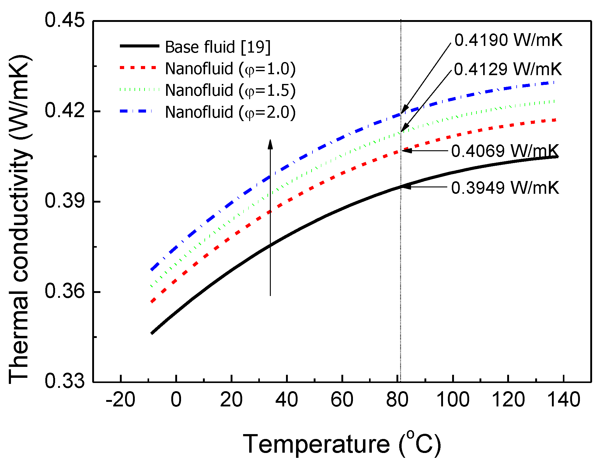
Figure 7 shows the thermal conductivity of the base fluid and the Al2O3 nanofluids determined by the Maxwell–Garnett model. The thermal conductivity of the nanofluid with φ = 1.5 % is expected to increase by 4.56% compared to the base fluid at 81 °C, as shown in Figure 7.

2.2.4. Specific Heat

The specific heat of the coolant determines the warming period for the diesel engine. The specific heat of the nanofluid is modeled using the analytical model from Xuan and Roetzel [28], which follows:
C p , n f = ( 1 φ ) ( ρ C p ) b f + φ ( ρ C p ) p ρ n f
where C p ,   n f is the specific heat of nanofluid, C p ,   b f is the specific heat of base fluid, ρ n f is the density of nanofluid, C p is the specific heat of nanoparticle, ρ is the density of nanoparticle, and φ is the volume fraction of nanofluid.
Figure 8 shows the specific heat of the base fluid and nanofluid determined by using Xuan and Roetzel’s model. At 81 °C, the specific heat of the nanofluid with φ = 1.5 % decreases by 1.43% compared to that of the base fluid.

2.2.5. Heat Transfer Coefficient

As shown in Figure 2, the ETMS of the diesel engine consists of many heat exchangers: the fan, pump, pipes, etc. To investigate the ETMS of the diesel engine, the correlation equation for the convection heat transfer coefficient should be derived for the cooling components such as tubes and pipes, as shown in Figure 4. The Nusselt number for turbulent flow of the base fluid in pipes can be calculated from the Dittus–Boeleter equation [29], which follows:
N u = 0.023 Re 0.8 Pr 0.4 0.6 Pr 160 Re 10000
where, for the base fluid, N u is the Nusselt number, Re is the Reynolds number, and Pr is the Prandtl number. From Equation (5), the heat transfer in the heat exchangers and pipes can be calculated from the following equations.
Q ˙ = A h b f   o r   n f ( T l i q u i d T w )   for   internal   heat   flow  
Q ˙ = A h   c o n s t . ( T a i r T w )   for   external   heat   flow  
where Q ˙ is the heat transfer rate, A is the area, h   c o n s t . is the constant heat transfer coefficient, and h b f   o r   n f is the heat transfer coefficient of base fluid or nanofluid calculated from the Equation (5). T b f   o r   n f , T a i r , and T w   are the base fluid or the nanofluid temperature, ambient temperature, and wall temperature of the heat exchangers and pipes, respectively.

2.3. Experimental Setup and Test Condition of the Diesel Engine

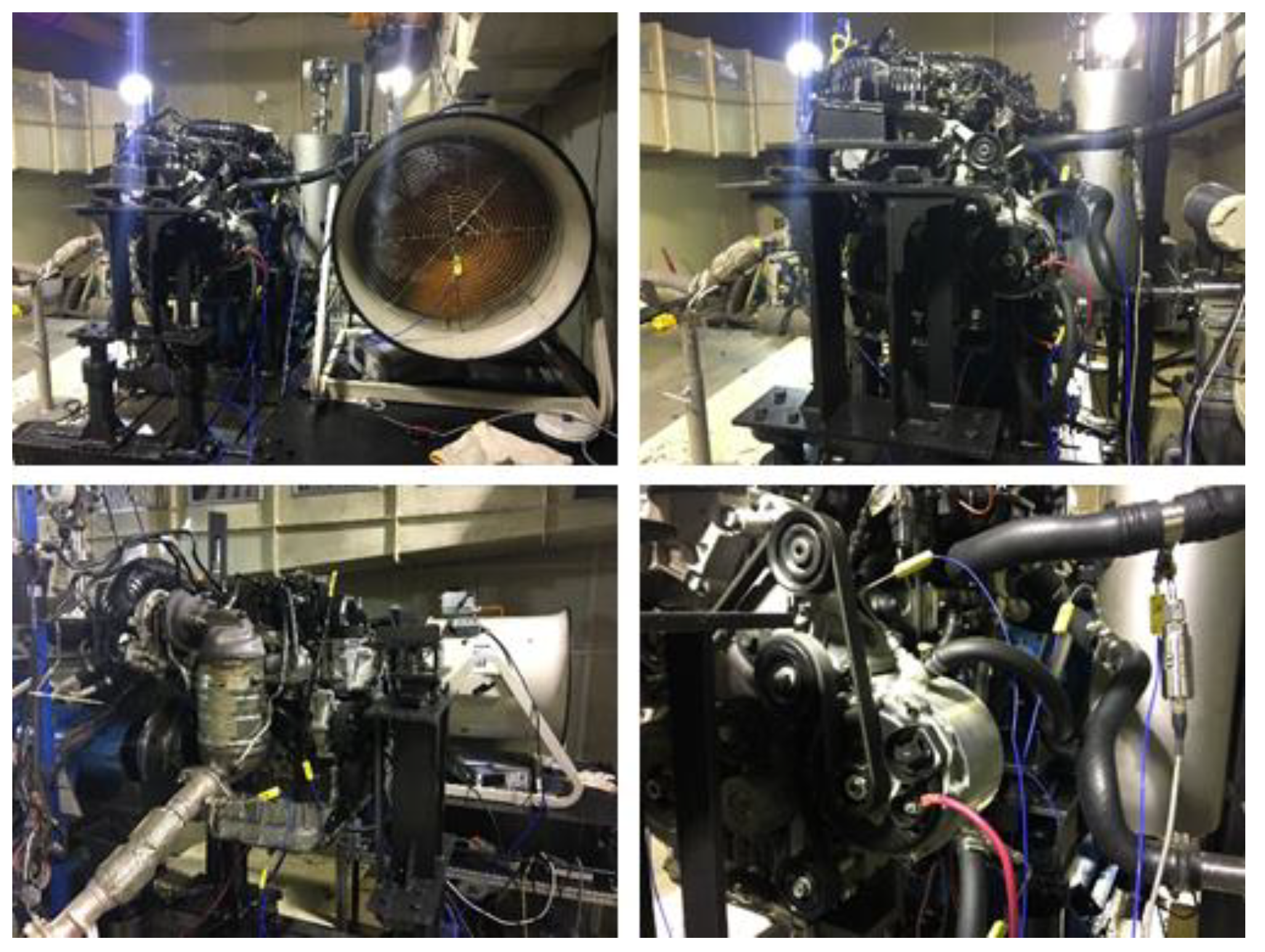
Figure 9 shows a photo of the 2 L diesel engine with an Al2O3 nanofluid and base fluid cooling system. Maximum torque of the diesel engine is 40 kg-m at an engine speed of 2000 rpm, and maximum power is 184 hp at an engine speed of 4000 rpm. The engine, which satisfies EURO-5 emission regulations [30], has a high-pressurized fuel supply system, common-rail system, electronic-controlled turbocharger, charge air cooler, and after-treatment of exhaust gas. The diesel engine specifications are summarized in Table 2. The total amount of coolant in the diesel engine system is about 8.5 L. The temperature of coolant is controlled by a thermostat, which is installed in the outlet of the engine water-jacket, as shown in Figure 2. As the temperature of the diesel engine reaches 80 °C, the thermostat begins to open the flow passage to the radiator and coolant flows to the radiator. The cooling air flow generated by the electrical fan removes heat from the radiator through tubes and louvered fins. Therefore, regardless of the type of coolant (base fluid or nanofluid), the temperature of the coolant maintains its 80 °C target constant temperature.
Table 3 summaries the engine operating modes for the evaluation of the thermal performance behavior of the diesel engine for base fluid and nanofluid. Total engine operating time is 4000 s and consists of engine idling, step-load for the uphill condition, and re-idling. After idling for 1000 s, a step-load of 216 Nm and 2050 rpm during 1500 s is specified, and afterward returns to idling for 1500 s. These modes can basically describe the dynamic characteristics of the warming, cooling, and cool-down of the diesel engine. First, during the engine idling condition, the coolant just circulates inside the engine before the engine warms. Then, during the uphill condition, it is possible to investigate the heat balance between the heat generation from the combustion chamber to obtain the required power and the heat transfer to outside air. Finally, during the engine re-idling condition, the engine cools through heat transfer from the engine block to the air.

3. Results and Discussion

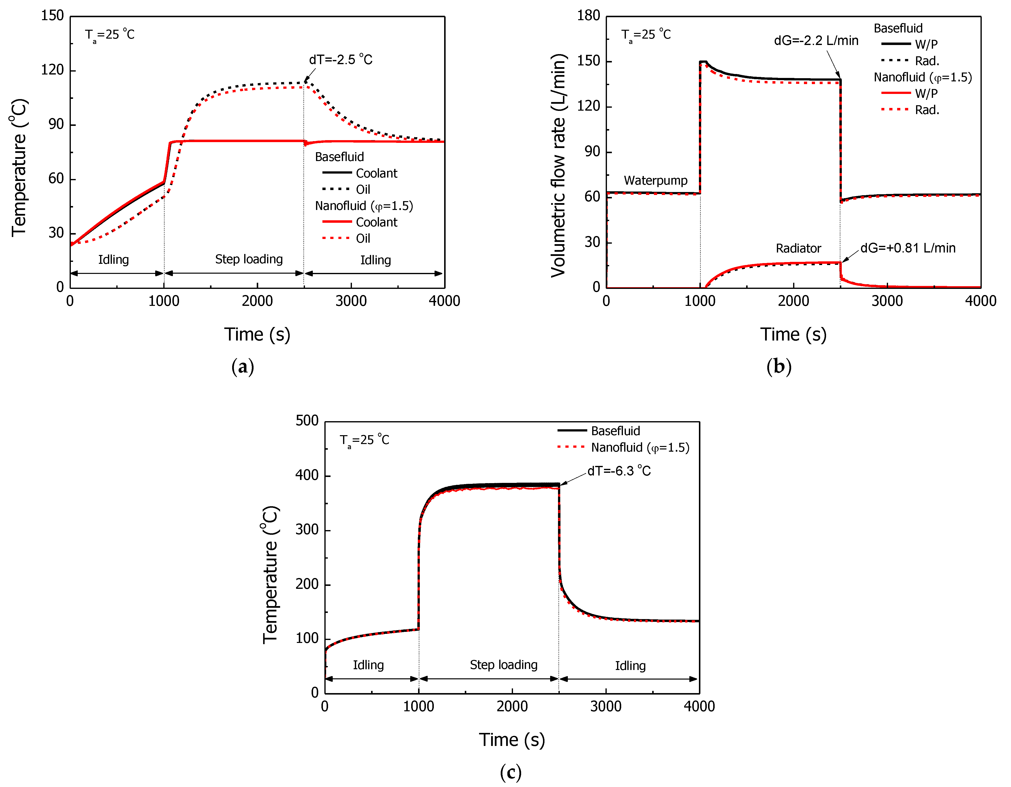
Figure 10 shows the thermal performance of the diesel engine with a cooling system of base fluid and Al2O3 nanofluid. The coolant temperature, oil temperature, and flow rate through the water pump and radiator were simulated during engine operating modes. As shown in Figure 11a, the engine coolant temperature and oil temperature gradually warmed during the first 1000 s. A significant portion of the heat from the combustion chamber was carried away by the oil through the diesel engine piston [31]. Then, the temperature of the engine coolant under the engine part-load condition from 1000 to 2500 s was maintained near 80 °C because it was controlled by the wax-type mechanical thermostat. However, because the oil was mainly cooled by the coolant through the oil cooler, the oil temperature gradually increased until a thermal equilibrium was reached near the end of the part-load condition. After the engine operated for 2500 s, the coolant temperature was maintained at 80 °C due to the heat balance between heating from the combustion chamber and cooling to ambient air. There was no cooling flow through the radiator because of bypassing from the thermostat. The oil temperature gradually decreased as the coolant temperature decreased; the coolant always flows through the oil cooler regardless the thermostat operation.
Nanofluid, with its higher thermal conductivity and higher heat transfer coefficient, absorbs more heat from the combustion chamber through the water-jacket, which is installed on the engine block. Owing to higher thermal performance of the nanofluid, the oil temperature of the nanofluid was kept lower than that of the base fluid during the part-load condition, as shown Figure 11a. At 2500 s, compared to the base fluid, the oil temperature for the nanofluid was 2.5 °C less. The experimental and numerical oil temperatures at 2500 s are summarized in Table 4. Although over-predicted in the simulation, it shows the better effect of nanofluid on thermal performance.
The flow rate through the water pump and the radiator are shown in Figure 10b. The flow rate of the water pump was determined by the opening ratio of the thermostat, which measures the temperature of the engine. During the initial 1000 s condition, the flow rate through the water pump was approximately 63 L/min; there was no radiator flow because it was before the engine had warmed. Since the water pump speed depends on the engine speed, the flow rate increased to 142 L/min during the part-load condition. Then it again decreased. Because the dynamic viscosity of the nanofluid was higher than that of the base fluid, the friction loss in the cooling system increased; the required pumping power also increased. Eventually, the total flow rate of nanofluid in the water-jacket decreased by 2.2 L/min, although the flow rate through the radiator with nanofluid increased by 0.81 L/min to dissipate more heat. Figure 10c shows the exhaust gas temperature. In the idle condition, the temperature was maintained at 110 °C and then reached about 382.3 degrees during the part-load condition. When the engine was driven back to idle, the exhaust gas temperature was again maintained near 120 °C. The exhaust gas temperature of the nanofluid numerically decreased by 6.34 °C compared to that of the base fluid. The overall thermal performance of the diesel engine for base fluid and nanofluid were compared with engine test results, which assured the reliability of the analysis results for the ETMS model.
Figure 11 shows the temperature of the piston and liner and the engine and radiator during the engine test conditions. The piston and liner are located in the center of the engine and their temperature is difficult to measure. To develop a high-powered diesel engine, it is crucial to decrease the maximum temperature of the piston and liner during the full load [31,32]. The piston temperature for the cooling system with nanofluid was 7.5 °C less compared to that of the base fluid. The temperature of the liner, located in the piston side and responsible for transferring heat from the combustion chamber to the engine water jacket, was effectively decreased by 8 °C. Figure 11b depicts the temperature of the engine coolant flowing out and the air temperature of the radiator in/out. As previously described, the coolant temperatures are controlled by the thermostat. Owing to the heat dissipation from the coolant to air through the radiator, the air temperature increased.
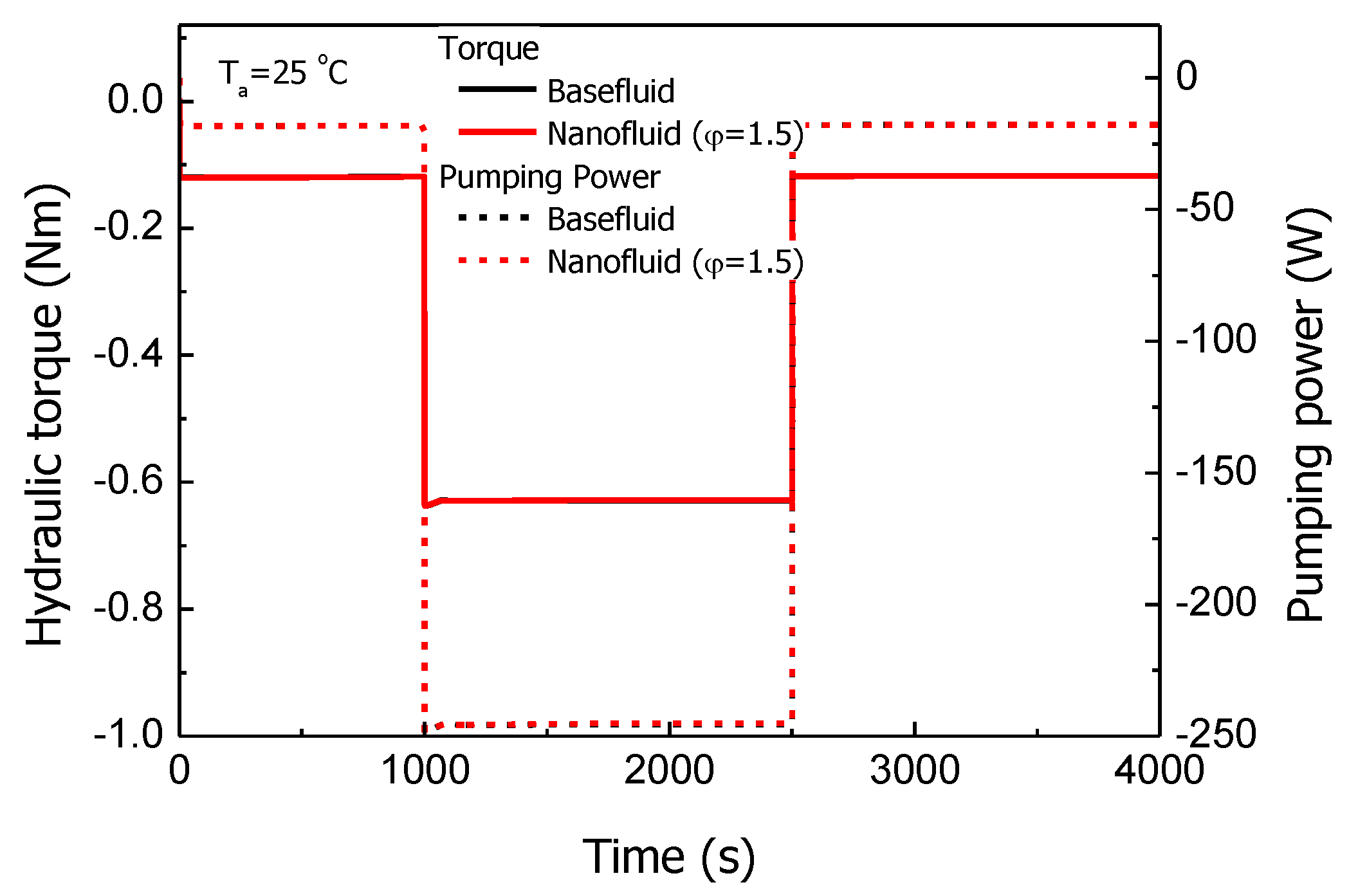
Figure 12 shows the water pump power for base fluid and nanofluid during the operating conditions. The pulley of the water pump is connected directly to a crankshaft through the pulley belt and the pumping power for the working fluid can affect the engine power. The pumping power increased due to the dynamic viscosity when applying nanofluid. However, as the pumping power of the water pump was very small compared to that of engine’s whole power; the effect on the engine’s whole power was negligible.
At 2500 s, which is the end of the part-load condition, the temperatures of the coolant and ambient air are constant. The heat generated from the combustion transferred to ambient air through the cooling system. When nanofluid is applied the cooling system, the thermal resistances decrease due to low thermal conductivity at the engine block and the heat exchangers, such as the water-cooled oil cooler and the radiator, including the tubes. Eventually, the total resistance from the combustion chamber to ambient air for the nanofluid becomes relatively small compared to that of the base fluid. Therefore, heat dissipation in the radiator increased by 1.12 kW. Nonetheless, the temperature of the piston, which is located at engine center, was reduced by 7.3 °C. In the diesel engine system, the lower temperature of the piston can effectively reduce thermomechanical fatigue and assures the reliability of the engine system.

4. Conclusions

Multi-disciplinary analysis was carried out to investigate the effect of working fluids on the thermal performance of a diesel engine. The ETMS models for base fluid, a 50/50 mixture of water and EG, and an Al2O3 nanofluid with a 1.5% volume and characterized by better thermal physical properties, were developed for the 2 L high-power diesel engine. Thermal performance such as the coolant temperature, the oil temperature, and the flow rate through the water pump and radiator, etc., was investigated during engine operating modes consisting of engine idling, step-load for the uphill condition, and re-idling. The coolant temperature was maintained at 80 °C due to the thermostat, which actively controls the coolant temperature, but the oil temperature gradually decreased as the coolant temperature was lowered by the oil cooler. At 2500 s, the oil temperature of the nanofluid experimentally and numerically was 0.7 and 2.5 °C less compared to those of the base fluid. During the step-load condition, the total flow rate of nanofluid decreased by 2.2 L/min, although the flow rate through the radiator with nanofluid increased by 0.81 L/min to obtain greater heat dissipation. Especially, the piston temperature with the cooling system with nanofluid was 7.55 °C less compared to that of the base fluid. The liner, located in the piston side and responsible for transferring the heat from the combustion chamber to the engine water jacket, effectively decreased by 8 °C. When the nanofluid was used in the cooling system, the total resistance from the combustion chamber to the ambient air for the nanofluid became relatively small compared to that of the base fluid. Therefore, heat dissipation in the radiator increased by 1.12 kW and the temperature of the piston, which is located at the engine center, was reduced by 7.3 °C. Application of the nanofluid could increase the reliability of the high-power diesel engine system. In the future, it will be possible to solve the heat-exchanger sizing problem and predict the fuel economy using the vehicle thermal management system model (VTMS).

Funding

This research was supported by Tongmyong University Research Grant 2019A018.

Institutional Review Board Statement

Not applicable.

Informed Consent Statement

Not applicable.

Data Availability Statement

Not applicable.

Conflicts of Interest

The author declares no conflict of interest.

References

  1. Roberts, A.; Brooks, R.; Shipway, P. Internal Combustion Engine Cold-Start Efficiency: A Review of the Problem, Causes and Potential Solutions. Energy Convers. Manag. 2014, 82, 327–350. [Google Scholar] [CrossRef] [Green Version]
  2. Bent, E.; Shayler, P.J.; Rocca, A.L.; Rouaud, C. The Effectiveness of Stop-Start and Thermal Management Measures to Improve Fuel Economy. In Proceedings of the Vehicle Thermal Management Systems Conference Proceedings (VTMS11), Coventry Technocentre, UK, 15–16 May 2013. [Google Scholar]
  3. Taylor, O.; Pearson, R.; Stone, R. Reduction of CO2 Emissions through Lubricant Thermal Management During the Warm Up of Passenger Car Engines. In SAE Technical Paper 2016-01-0892; SAE International: Warrendale, PA, USA, 2016. [Google Scholar]
  4. Shayler, P.J.; Allen, A.J.; Leong, D.K.M.; Pegg, I.; Brown, A.; Dumenil, J.C. Characterising Lubricating Oil Viscosity to Describe Effects on Engine Friction. In SAE Technical Paper 2007-01-1984; SAE International: Warrendale, PA, USA, 2007. [Google Scholar]
  5. Dhinesh, K.D.; Valan, A.A. A Review on Preparation, Characterization, Properties and Applications of Nanofluids. Renew. Sustain. Energy Rev. 2016, 60, 21–40. [Google Scholar]
  6. Minli, B.; Zhe, X.; Jizu, L. Application of Nanofluids in Engine Cooling System. In SAE Technical Paper 2008-01-1821; SAE International: Warrendale, PA, USA, 2008. [Google Scholar]
  7. Nor, A.C.S.; Muhammad, N.A.W.M.Y.; Rizalman, M. Recent Advancement of Nanofluids in Engine Cooling System. Renew. Sustain. Energy Rev. 2017, 75, 137–144. [Google Scholar]
  8. Choi, S.U.S.; Eastman, J.A. Enhancing Thermal Conductivity of Fluids with Nanoparticles. ASME FED 1995, 231, 99–105. [Google Scholar]
  9. Gabriela, H.; Angel, H. Application of Nanofluids in Heat Exchangers: A Review. Renew. Sustain. Energy Rev. 2012, 16, 5625–5638. [Google Scholar]
  10. Choi, S.U.S.; Yu, W.; Hull, J.R.; Zhang, Z.G.; Lockwood, F.E. Nanofluids for Vehicle Thermal Management. In SAE Technical Paper 2001-01-1706; SAE International: Warrendale, PA, USA, 2001. [Google Scholar]
  11. Tzeng, S.C.; Lin, C.W.; Huang, K.D. Heat Transfer Enhancement of Nanofluids in Rotary Blade Coupling of Four-Wheel-Drive vehicles. Acta Mech. 2005, 179, 11–23. [Google Scholar] [CrossRef]
  12. Zhang, K.J.; Wang, D.; Hou, F.J.; Jiang, W.H.; Wang, F.R.; Li, J.; Liu, G.J.; Zhang, W.X. Characteristic and Experiment Study of HDD Engine Coolants. Neiranji Gongcheng/Chin. Internal. Combust. Engine Eng. 2007, 28, 75–78. [Google Scholar]
  13. Saripella, S.K.; Yu, W.; Routbort, J.L.; France, D.M.; Rizwan, U. Effects of Nanofluid Coolant in a Class 8 Truck Engine. In SAE Technical Papers 2007-01-2141; SAE International: Warrendale, PA, USA, 2007. [Google Scholar]
  14. Ali, M.; El-Leathy, A.M.; Al-Sofyany, Z. The Effect of Nanofluid Concentration on the Cooling System of Vehicles Radiator. Adv. Mech. Eng. 2014, 6, 962510. [Google Scholar] [CrossRef] [Green Version]
  15. Esfe, M.H.; Esfandeh, S.; Afrand, M.; Rejvani, M.; Rostamian, S.H. Experimental Evaluation, New Correlation Proposing and ANN modeling of Thermal Properties of EG Based Hybrid Nanofluid Containing ZnO-DWCNT Nanoparticles for Internal Combustion Engines Applications. Appl. Therm. Eng. 2018, 133, 452–463. [Google Scholar] [CrossRef]
  16. Balitskii, A.; Kindrachuk, M.; Volchenko, D.; Abramek, K.F.; Balitskii, O.; Skrypnyk, V.; Zhuravlev, D.; Bekish, I.; Ostashuk, M.; Kolesnikov, V. Hydrogen Containing Nanofluids in the Spark Engine’s Cylinder Head Cooling System. Energies 2022, 15, 59. [Google Scholar] [CrossRef]
  17. Erkan, A.; Tüccar, G.; Tosun, E.; Özgür, T. Comparison of Effects of Nanofluid Utilization (Al2O3, SiO2, TiO2) with Reference Water in Automotive Radiators on Exergetic Properties of Diesel Engines. SN Appl. Sci. 2021, 3, 365. [Google Scholar] [CrossRef]
  18. Vajjha, R.S.; Das, D.K.; Namburu, P.K. Numerical Study of Fluid Dynamic and Heat Transfer Performance of Al2O3 and CuO Nanofluids in the Flat Tubes of a Radiator. Int. J. Heat Fluid Flow 2010, 31, 613–621. [Google Scholar] [CrossRef]
  19. Huminic, G.; Huminic, A. Numerical Analysis of Laminar Flow Heat Transfer of Nanofluids in a Flattened Tube. Int. Commun. Heat Mass Transf. 2013, 44, 52–57. [Google Scholar] [CrossRef]
  20. Abbasi, M.; Baniamerian, Z. Analytical Simulation of Flow and Heat Transfer of Two-Phase Nanofluid (Stratified Flow Regime). Int. J. Chem. Eng. 2014, 2014, 474865. [Google Scholar] [CrossRef] [Green Version]
  21. Delavari, V.; Hashemabadi, S.H. CFD Simulation of Heat Transfer Enhancement of Al2O3/water and Al2O3/ethylene glycol Nanofluids in a Car Radiator. Appl. Therm. Eng. 2014, 73, 390. [Google Scholar] [CrossRef]
  22. AVL. CRUISE M User Manual 2020R 2. Available online: https://www.avl.com/cruise-m (accessed on 11 August 2022).
  23. Fotukian, S.M.; Nasr Esfahany, M. Experimental Investigation of Turbulent Convective Heat Transfer of Dilute γ-Al2O3/water Nanofluid inside a Circular Tube. Int. J. Heat Fluid Flow 2020, 31, 606–612. [Google Scholar] [CrossRef]
  24. Sommers, A.D.; Yerkes, K.L. Experimental Investigation into the Convective Heat Transfer and System-level Effects of Al2O3-Propanol Nanofluid. J. Nanopart. Res. 2010, 12, 1003–1014. [Google Scholar] [CrossRef]
  25. Pak, B.C.; Cho, Y. Hydrodynamic and Heat Transfer Study of Dispersed Fluids with Submicron Metallic Oxide Particle. Exp. Heat Transf. 1998, 11, 151–170. [Google Scholar] [CrossRef]
  26. Einstein, A. Eine neue Bestimmung der Moleküldimensionen. Ann. Phys. 1906, 324, 289–306. [Google Scholar] [CrossRef] [Green Version]
  27. Maxwell, J.C. A Treatise on Electricity and Magnetism, 1st ed.; Clarendon Press: Oxford, UK, 1873; pp. 360–366. [Google Scholar]
  28. Xuan, Y.; Roetzel, W. Conceptions for Heat Transfer Correlation of Nanofluids. Int. J. Heat Mass Transf. 2000, 43, 3701–3707. [Google Scholar] [CrossRef]
  29. Dittus, F.W.; Boelter, L.M.K. Heat Transfer in Automobile Radiators of the Tubular Type. Univ. Calif. Publ. Eng. 1930, 2, 443–461. [Google Scholar] [CrossRef]
  30. Wikipedia. Hyundia R Engine. Available online: https://en.wikipedia.org/wiki/Hyundai_R_engine (accessed on 11 August 2022).
  31. Mancaruso, E.; Sequino, L. Measurements and Modeling of Piston Temperature in a Research Compression Ignition Engine during Transient Conditions. Results Eng. 2019, 2, 100007. [Google Scholar] [CrossRef]
  32. Reichstein, S.; Weiss, R.; Kenningley, S.; Lades, K.; Konrad, P.; Doemenburg, F. High-performance Cast Aluminum Pistons for Highly Efficient Diesel Engines. In SAE Technical Papers 2007-01-1438; SAE International: Warrendale, PA, USA, 2007. [Google Scholar]
Figure 1. Advanced heat transfer in nanofluids.
Machines 10 01023 g001
Figure 2. Schematic diagram of the diesel engine’s thermal management system.
Machines 10 01023 g002
Figure 3. Multi-disciplinary model of the diesel engine using CruiseM.
Machines 10 01023 g003
Figure 4. Heat transfer and pressure-drop model in the cooling system.
Machines 10 01023 g004
Figure 5. Density modeling of the base fluid and Al2O3 nanofluids.
Machines 10 01023 g005
Figure 6. Dynamic viscosity modeling of the base fluid and Al2O3 nanofluids.
Machines 10 01023 g006
Figure 7. Thermal conductivity modeling of the base fluid and Al2O3 nanofluids.
Machines 10 01023 g007
Figure 8. Specific heat modeling of the base fluid and a Al2O3 nanofluid.
Machines 10 01023 g008
Figure 9. Photo of the engine experimental setup and the test engine.
Machines 10 01023 g009
Figure 10. Thermal performance results of the diesel engine with Al2O3 nanofluids at 216 Nm step-load and 2050 rpm engine speed: (a) coolant and oil temperatures; (b) water pump and radiator flow rates; (c) exhaust gas temperatures.
Machines 10 01023 g010
Figure 11. Temperature results for the diesel engine with Al2O3 nanofluids at 216 Nm step-load and 2050 rpm engine speed: (a) piston and liner; (b) engine and radiator.
Machines 10 01023 g011
Figure 12. Torque and power results of the diesel engine with Al2O3 nanofluids at 216 Nm step-load and 2050 rpm engine speed.
Machines 10 01023 g012
Table 1. Properties of the Al2O3 particles.
Nanosized ParticlesMean Diameter
(mm)
Density
(kg/m3)
Thermal Conductivity (W/mK)Specific Heat
(kJ/kg-K)
Al2O32037008800.046
Table 2. Specifications of the diesel engine.
ParameterDescription
TypeDI diesel engine with e-VGT
Bore × Stroke (mm)84.0 × 90.0
Displacement (cc)1995
Compression ratio (-)16.0
Fuel injection systemBosch common-rail system
Max. power (HP/rpm)184/4000
Max. torque (kg-m/rpm)40/2000
Table 3. Engine operating modes.
StepEngine ConditionDriving Time
1Idle1000 s
22050 rpm@216 Nm1500 s
3Idle1500 s
Table 4. Oil temperature variation results at 2500 s.
Base Fluid (°C)Al2O3 Nanofluid (°C)dT (°C)
Experiment113.03112.34−0.7
Simulation113.4110.91−2.5
Publisher’s Note: MDPI stays neutral with regard to jurisdictional claims in published maps and institutional affiliations.