Article

A Trajectory Tracking Approach for Aerial Manipulators Using Nonsingular Global Fast Terminal Sliding Mode and an RBF Neural Network

School of Mechanical and Electrical Engineering, Henan University of Science and Technology, Luoyang 471000, China
*
Author to whom correspondence should be addressed.
Machines 2022, 10(11), 1021; https://doi.org/10.3390/machines10111021
Submission received: 30 September 2022 / Revised: 29 October 2022 / Accepted: 1 November 2022 / Published: 3 November 2022
(This article belongs to the Special Issue Advanced Control of Unmanned Aerial Vehicles (UAV))

Abstract

:
An unmanned aerial manipulator (UAM) is a novel flying robot consisting of an unmanned aerial vehicle (UAV) and a multi-degree-of-freedom (DoF) robotic arm. It can actively interact with the environment to conduct dangerous or inaccessible tasks for humans. Owing to the underactuated characteristics of UAVs and the coupling generated by the rigid connection with the manipulator, robustness and a high-precision controller are critical for UAMs. In this paper, we propose a nonsingular global fast terminal sliding mode (NGFTSM) controller for UAMs to track the expected trajectory under the influence of disturbances based on a reasonably simplified UAM system dynamics model. To achieve active anti-disturbance and high tracking accuracy in a UAM system, we incorporate an RBF neural network into the controller to estimate lumped disturbances, including internal coupling and external disturbances. The controller and neural network are derived according to Lyapunov theory to ensure the system’s stability. In addition, we propose a set of illustrative metrics to evaluate the performance of the designed controller and compare it with other controllers by simulations. The results show that the proposed controller can effectively enhance the robustness and accuracy of a UAM system with satisfactory convergence. The experimental results also verify the effectiveness of the proposed controller.

1. Introduction

Unmanned aerial vehicles (UAVs) equipped with various types of equipment play an increasingly important role in aerial photography, search, surveillance, etc. [1,2,3,4]. In particular, unmanned aerial manipulators (UAMs) consisting of a UAV and robotic manipulators have potential operational applications, providing improved maneuverability relative to mobile manipulators. UAMs can substitute humans to actively perform aerial missions, reducing cost and personal injury [5] associated with tasks such as disaster rescue [6,7], social security [7,8] and object delivery [9,10]. Quadrotor-based UAMs have the advantages of uncomplicated composition and easy maintenance, with numerous structural solutions. However, the underactuated characteristics of quadrotors, the coupling generated by the rigid connection with the manipulator and the reaction force of the manipulator motion on the quadrotor reduce the stability of UAMs, making it difficult to achieve precise control. Therefore, it is crucial to design a robust, high-precision UAM controller with rapid response capability [11].
A variety of control methods have been proposed to control aerial manipulator systems, such as proportional-integral-derivative (PID) control [12,13], model-predictive control [14,15,16], impedance control [17,18], adaptive control [19,20,21], etc. PID control is the most widely used method, with the advantages of seldomly considering model information, simple calculation and easy implementation. A controller based on the PID method was designed for a UAM to conduct a hammering test on a bridge pier for defect inspection [12]. However, the robustness of the PID controller was limited under the influence of disturbances. A model-predictive controller was designed for visual servo control of an aerial manipulator, as well as aerial grasping of cylindrical objects [14]. An impedance controller was developed for an aerial manipulator to suppress disturbances caused by manipulator movements when the system performed aerial tasks [18]. An adaptive controller capable of estimating online load parameters was designed for a UAM to transport an unknown object and track the desired trajectory [20]. However, these operations were performed with the system slowly changing or with uncomplicated external disturbances. Under real-world conditions, the quadrotor is very sensitive to interference, owing to its underactuated and strong coupling characteristics. Therefore, the robust control of aerial manipulators is a critical problem to be solved.
Sliding mode (SM) control is a variable structure control that forces the system to move along the trajectory of the predetermined sliding surface by varying purposefully based on the system state. With the advantage of fast convergence and anti-disturbance characteristics, SM control has become one of the most widely used robust nonlinear control methods. Many studies have been conducted on the use of SM for aerial manipulators conducting aerial tasks. An adaptive SM controller was developed for precise control of the quadrotor position and manipulator motion to accurately pick up and transfer objects [21]. A passive adaptive SM controller was developed to control the position and velocity of a UAM using an image-based servo [22]. A PID- and SM-based controller was proposed to perform precisely desired trajectory tracking for an aerial manipulator system [23]. A composite controller combined proportional derivative (PD), SM-based aerial manipulator system decoupled into two subsystems was designed for a UAM to accurately track the desired trajectory [24]. The above experimental results show that an SM controller can effectively improve the robustness, accuracy and decoupling ability of a UAM without guaranteeing the error convergence time. Hence, to ensure zero convergence of system errors in finite time, researchers have improved the SM function to enhance control performance and ensure sufficient response speed to meet the requirements of rapid system change.
The position or velocity errors of a UAM during missions are related to the underactuation and instability of the quadrotor. Therefore, the response and convergence time of the quadrotor are crucial to the operation stability of a UAM. A novel robust terminal sliding mode control method was proposed to guarantee system converged to a stability point in a limited time [25]. An adaptive integral-type terminal sliding mode controller was proposed for the quadrotor to track the attitude and position under the conditions of model uncertainties and external disturbances [26]. A time delay, estimation-based, nonsingular terminal sliding mode controller was proposed for a UAM to enhance the joint desired angle tracking accuracy of the manipulator [27]. A controller based on SM and an extended-state observer was designed for a quadrotor to precisely track a spiral curve under the influence of disturbances [28]. The above findings demonstrate that the system can reliably perform aerial missions with little regard for external disturbances. However, various unavoidable environmental disturbances, such as gusts of wind, seriously affect the system’s stability in practical applications. Therefore, the ability to actively suppress interference is critical for UAMs.
The aim of the present study is to improve general SM function design a nonsingular global fast terminal sliding mode (NGFTSM) function. Combined with a radial basis function (RBF) neural network, a composed controller is proposed for an aerial manipulator to ensure reliable tracking of desired trajectories under the influence of external disturbances. The UAM system dynamics model is simplified under given conditions and decoupled into two subsystems to design an NGFTSM controller. To achieve active anti-disturbance and high-accuracy control of a UAM, we incorporate an RBF neural network into the controller to estimate lumped disturbances, including internal coupling and external disturbances. In the previous studies [29,30], neural networks have been used to approximate unknown models. The proposed controller and neural network are derived according to Lyapunov theory to ensure the system’s stability. A final simulation and actual flight verify the reliability of the proposed control method.
The remainder of this paper is organized as follows. In Section 2, we present the UAM dynamics model with reasonable simplification. In Section 3, we propose a control scheme for a UAM and conduct a Lyapunov analysis of the system’s stability. Then, in Section 4 and Section 5, several simulations are performed for comparison with other control methods, and an actual flight test is carried out to verify the performance of the proposed controller. Finally, in Section 6 we present our concluding remarks.

2. Materials and Methods

2.1. Kinematic Model

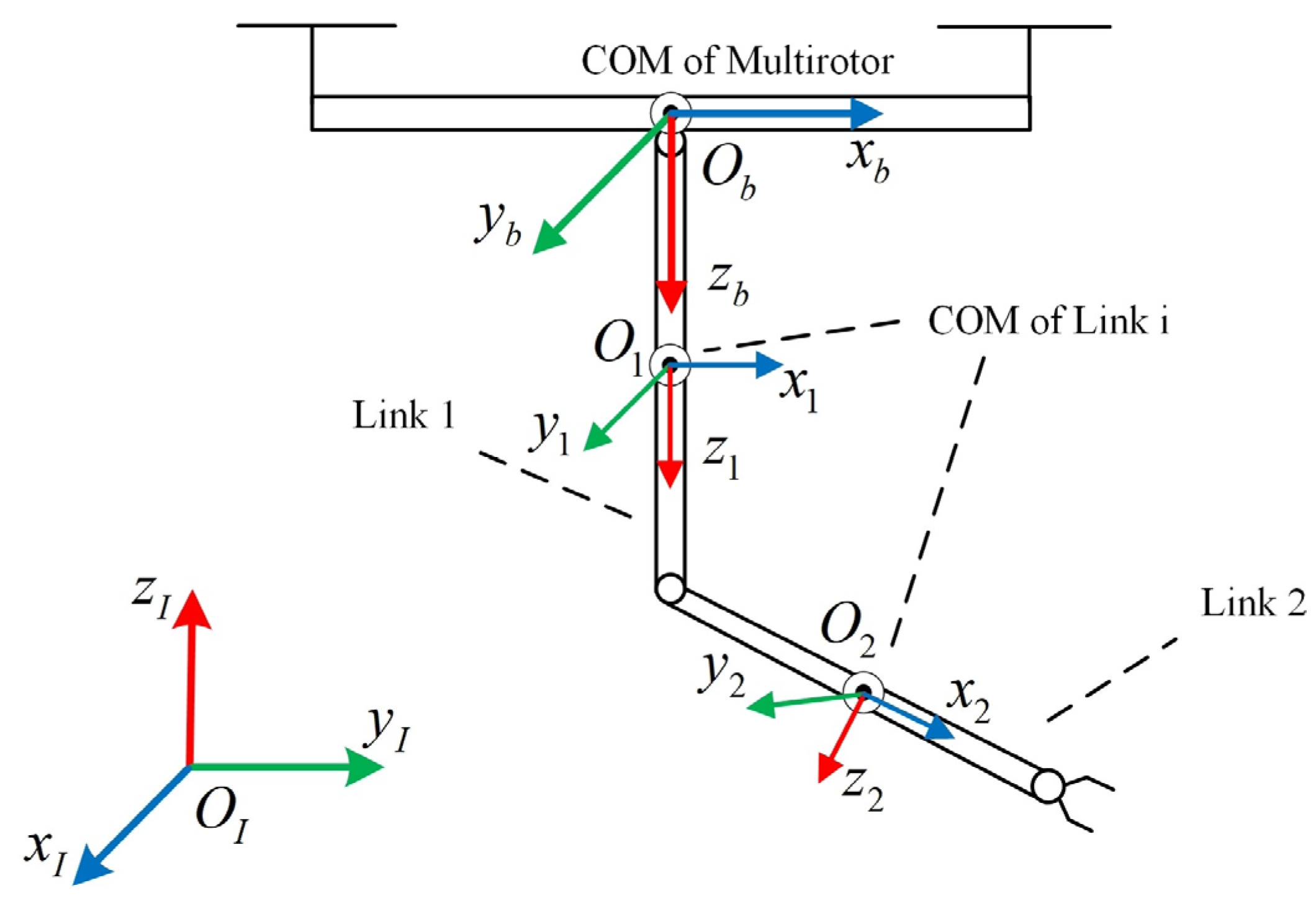
Figure 1 shows the structure of the reference frames. The inertial coordinate frame is denoted as O I , O b and O i represent the body coordinate frames fixed to the quadrotor and links, respectively. All body-fixed coordinate frames are located at the center of mass of their respective rigid bodies. The position of the center of mass (COM) of the quadrotor in the inertial frame is p = [ x   y   z ] T , the Euler angles of the quadrotor are expressed Φ = [ ϕ   θ   ψ ] T and the joint angles of the two-DoF manipulator are expressed φ = [ φ 1   φ 2 ] T . The vector containing all the generalized coordinate variables is defined as q = [ p T   Φ T   φ T ] T .
p ˙ and p ˙ b represent the translational velocity of the center of mass of the quadrotor in the inertial coordinate and body-fixed frame, respectively; ω and ω b represent the angle velocity of the quadrotor in the inertial and body-fixed frame, respectively; R b is the transformation matrix from the body coordinate to the inertial coordinate; and T is the transformation matrix from Φ ˙ to ω .
p ˙ = R b p ˙ b
ω b = R b T T Φ ˙ = Q Φ ˙
p i ( i = 1 , 2 ) and p i b represent the position of the mass of link i = 1 , 2 in the inertial coordinate and body-fixed frame, respectively. The translational and angular velocity of each manipulator link are related to φ ˙ and the Jacobian matrix, J v i R 2 × 2 and J ω i R 2 × 2 . The translational and angular velocity of each link in the inertial frame are expressed as follows.
p ˙ i = p ˙ + ω ^ b R b p i b + R b J v i φ ˙
ω i = ω + R b J ω i φ ˙

2.2. Dynamics Model

The dynamical model of the system is established according to eh Euler–Lagrange method based on the kinematic model of the system.
d d t L q ˙ L q = τ + τ e x t
Δ = K U
where K and U are the total kinetic and potential energy of the aerial manipulator system, respectively; he generalized force is τ = [ τ 1   τ 2     τ 8 ] T ; the generalized force in the x , y and z directions is [ τ 1   τ 2   τ 3 ] T . The generalized torque corresponding to the Euler angle is [ τ 4   τ 5   τ 6 ] T ; the generalized torque corresponding to link i is [ τ 7   τ 8 ] T ; and τ e x t indicates the external disturbance applied to the system.
K = K b + i = 1 2 K i
K b = 1 2 p ˙ T m b p ˙ + 1 2 Φ ˙ T T T R b I b R b T T Φ ˙
K i = 1 2 p ˙ i T m i p ˙ i + 1 2 ω i T ( R b R i ) I i ( R b R i ) T ω i
where m b and m i are the masses of the quadrotor and link i , respectively; I is the inertial matrix; and the total potential energy is defined as:
U = m b g e 3 T p + i = 1 2 m i g e 3 T ( p + R b p i b )
where e 3 = [ 0   0   1 ] T . The dynamic equation of the system can be expressed as:
M ( q ) q ¨ + C ( q , q ˙ ) q ˙ + G ( q ) = τ + τ e x t
where M ( q ) is the mass matrix, C ( q , q ˙ ) is the Coriolis matrix and G ( q ) is the gravity matrix.

2.3. Model Simplification

Equation (11) can be rewritten in block matrix form as:
[ M 11 M 12 M 13 M 21 M 22 M 23 M 31 M 32 M 33 ] [ p ¨ Φ ¨ φ ¨ ] + [ C 11 C 12 C 13 C 21 C 22 C 23 C 31 C 32 C 33 ] [ p ˙ Φ ˙ φ ˙ ] + [ G 1 G 2 G 3 ] = [ τ p τ Φ τ φ ] + [ τ p e x t τ Φ e x t τ φ e x t ]
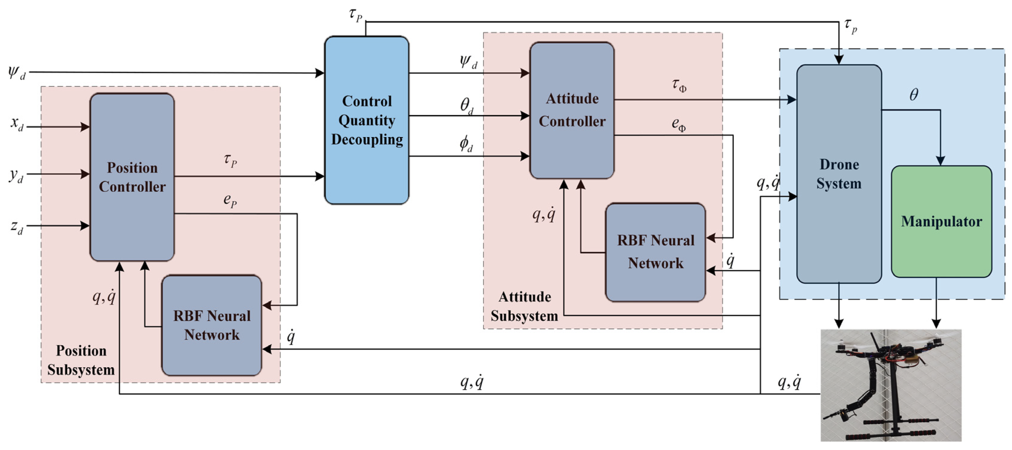
Because the manipulator joint rotation speed is much slower than the quadrotor movement, the first and above derivatives of the manipulator joint angle ( φ = [ φ 1   φ 2 ] T ) can be assumed to be zero, yielding the dynamic model of the quadrotor subsystem. The aerial manipulator control framework is shown in Figure 2.
[ M 11 M 12 M 21 M 22 ] [ p ˙ Φ ¨ ] + [ C 11 χ C 12 χ C 21 χ C 22 χ ] [ p ˙ Φ ˙ ] + [ G 1 G 2 ] = [ τ p τ Φ ] + [ τ p e x t τ Φ e x t ]
where [ C 11 χ C 12 χ C 21 χ C 22 χ ] = [ C 11 C 12 C 21 C 22 ] φ ˙ i = 0 ; τ p = [ τ 1 τ 2 τ 3 ] T ; τ Φ = [ τ 4 τ 5 τ 6 ] T ; τ φ = [ τ 7 τ 8 ] T .

3. Materials and Methods

In this section, we propose a controller based on the nonsingular global fast terminal sliding mode (NGFTSM) and an RBF neural network. The generalized state vector is computed by the dynamic model of the UAM and subtracted from the desired value to obtain the tracking error. Subsequently, the tracking error and its derivative are substituted into the nonlinear sliding mode surface function to calculate the sliding mode variable and imported into the proposed controller with this variable. To avoid uncertainties caused by disturbances and system imperfections and improve the trajectory tracking performance of the UAM, an RBF neural network estimates lumped disturbances containing the internal coupling, modelling errors and external disturbances and compensates for the controller.
ζ = [ p T Φ T ] T is the state variable of the quadrotor, and U = [ τ p T τ Φ T ] T is the system input. Equation (13) can be rewritten as:
M χ ζ ¨ + C χ ζ ˙ + G χ = U + U e x t
where M χ = [ M 11 M 12 M 21 M 22 ] ; C χ = [ C 11 χ C 12 χ C 21 χ C 22 χ ] ; G χ = [ G 1 G 2 ] ; U e x t = [ τ p e x t τ Φ e x t ] .
The general quadrotor system is divided into outer and inner rings, and the desired Euler angles are generated from the outer ring. In Equation (14), calculation of the outer-loop control input ( τ p ) requires Φ ¨ of the inner loop, which is unknown. Therefore, to eliminate the coupling between the inner and outer rings and possible algebraic-loop problems in simulation, we set M 12 = 0 , yielding the new control input [31]:
M χ ζ ¨ + C χ ζ ˙ + G χ = U + U e x t

3.1. Position Controller Design

The system position error ( e ) and nonsingular global fast terminal sliding mode function ( s ) are defined as:
e = p d p
s = e ˙ + Γ Θ ( e ) + Λ H ( e )
where e = [ e 1   e 2   e 3 ] T ; s = [ s 1   s 2   s 3 ] T ; Γ = d i a g ( α 1 , α 2 , α 3 ) ; Θ ( e ) = [ e 1 k   e 2 k   e 3 k ] T ; Λ = d i a g ( 1 β 1 , 1 β 2 , 1 β 3 ) ; H ( e ) = [ | e 1 | μ v sgn ( e 1 )   | e 2 | μ v sgn ( e 2 ) | e 3 | μ v sgn ( e 3 ) ] T ; α i , β i > 0 ; μ > v ; k , μ , v are all positive odd numbers; and sgn ( e ) is the error switching function. The control law is expressed as follows.
p ¨ = p ¨ d + Γ Θ ˙ ( e ) + Λ H ˙ ( e ) + λ s + η sgn ( s )
τ p = M 11 p ¨ + C 11 χ p ˙ + C 12 χ Φ ˙ + G 1 τ ^ p e x t
where λ = d i a g ( λ 1 , λ 2 λ 8 ) , λ i > 0 ; η sgn ( s ) is the robust term to overcome the neural network approximation error; and τ ^ p e x t is the estimation of the lumped disturbances of the position system from the RBF neural network. Therefore, the expected Euler angle of the inner ring can be calculated according to Equations (20)–(22) [23].
{ z = τ p τ p x = [ cos ψ d sin ψ d 0 ]
{ z b = z y b = z × x z × x x b = z b × y b R = [ x b y b z b ]
{ θ d = a r c tan 2 ( R ( 3 , 1 ) , R ( 1 , 1 ) 2 + R ( 2 , 1 ) 2 ) ϕ d = a r c tan 2 ( R ( 2 , 1 ) cos θ d , R ( 1 , 1 ) cos θ d )
where z is the unit vector of the z axis in the body coordinate system, x is the unit vector of the x axis in the body coordinate system, ψ d is the desired yaw angle, R is the rotation matrix of the expected pose and arctan 2 is a tangent function that is calculated as:
arctan 2 ( y , x ) = { arctan ( y x ) x > 0 arctan ( y x ) + π y 0 , x < 0 arctan ( y x ) π y < 0 , x < 0 π 2 y > 0 , x = 0 π 2 y < 0 , x = 0 u n d e f i n e d y = 0 , x = 0  

3.2. Attitude Controller Design

The tracking error and nonsingular global fast terminal sliding mode function of the attitude loop are defined as Equations (16) and (17), and the control input of the inner loop is obtained as follows.
Φ ¨ = Φ ¨ d + Γ Θ ˙ ( e ) + Λ H ˙ ( e ) + λ s + η sgn ( s )
τ Φ = M 21 p ¨ + M 22 p ¨ + C 21 χ p ˙ + C 22 χ Φ ˙ + G 2 τ ^ Φ e x t
where τ ^ Φ e x t is the lumped disturbances estimation of the attitude system from the RBF neural network. To avoid dynamic changes in the attitude system affecting the stability of the position system, attitude controller gains need to be adjusted to ensure that the attitude errors converge faster than the position errors [31].

3.3. RBF Neural Network Design and Stability Judgement

Because the controllers have the same design form, the x channel is used as an example to design the RBF neural network.
h j = exp ( ξ c j 2 b j 2 )
f = W T h ( ξ ) + ε
where ξ is the network input; W is the ideal network weight; ε is the network approximation error, where | ε | ε N ; c j and b j are the Gaussian function parameters; h = [ h j ] T is the output of the Gaussian function; and f is the actual network output. The network input is defined as ξ = [ e 1   e ˙ 1 ] T , and the estimation output is defined as:
f ^ ( ξ ) = W ^ T h ( ξ )
Because RBF neural networks have excellent generalization ability and approximation performance, we introduce a virtual variable ( F ). The virtual variable of the position system is defined as F ^ p = [ f ^ 1   f ^ 2   f ^ 3 ] T , and the position dynamics model can be rewritten as:
p ¨ = M 11 1 τ p + F p M 11 1 ( C 11 χ p ˙ + C 12 χ Φ ˙ + G 1 )
F p = M ( q ) 1 τ p e x t
Therefore, the time derivative of the sliding mode function and the estimation of the neural network can be obtained from Equations (18) and (19).
s ˙ = p ¨ d p ¨ + Γ Θ ˙ ( e ) + Λ H ˙ ( e ) = p ¨ d λ s η sgn ( s ) M ( q ) 1 ( τ p e x t τ ^ p e x t ) = λ s η sgn ( s ) F ˜ p
F ˜ p = [ f ˜ 1   f ˜ 2   f ˜ 3 ] T = M ( q ) 1 ( τ p e x t τ ^ p e x t ) = F p F ^ p
f ˜ = f f ^ = W T h ( ξ ) + ε W ^ T h ( ξ ) = W ˜ T h ( ξ ) + ε
where f ˜ is the neural network estimation for each position system channel. To obtain the network weight ( W ^ ) and prove the stability of the controller, the x channel is taken as an example to design the Lyapunov function.
V = V a + V r + V s = 1 2 s 1 2 + 1 2 δ W ˜ T W ˜ + 1 2 e 1 2
Then, s 1 = 0 is set as the sliding surface of the system, and Equation (17) can be rewritten as:
e ˙ 1 = α 1 e 1 k 1 β 1 | e 1 | μ v sgn ( e 1 )
where V a represents the process of the system approaching the sliding surface, δ > 0 , V r represents the process of neural network approximation for lumped disturbances and V s represents the convergence process after the system reaches the sliding mode surface. Therefore, the time derivative of the Lyapunov function can be written as:
V ˙ = s 1 s ˙ 1 + δ W ˜ T W ˜ ˙ + e 1 e ˙ 1 = s 1 ( λ 1 s 1 η 1 sgn ( s 1 ) f ˜ 1 ) δ W ˜ T W ^ ˙ e 1 ( α 1 e 1 k + 1 β 1 | e 1 | μ ν sgn ( e 1 ) ) = W ˜ T ( s 1 h ( ξ ) + δ W ^ ˙ ) λ 1 s 1 2 ( ε s 1 + η 1 | s 1 | ) ( α 1 e 1 k + 1 + 1 β 1 | e 1 | μ + ν ν )
Accordingly, η 1 > ε N , and the weight-adaptive law is defined as W ^ ˙ = 1 δ s 1 h ( ξ ) . Because δ , λ 1 , α 1 , β 1 , η 1 are all positive numbers and k + 1 is an even number, we V 0 , V ˙ 0 and V V ˙ 0 . The system is asymptotically stable according to the Lyapunov stability criterion, and the error can gradually converge to zero from any initial value. In addition, the neural network output ( f ^ 1 ) of channel x can be obtained according to Equation (28). Similarly, the neural network output ( f ^ i ) of other channels can be determined. Hence, the lumped interference estimation of the position and attitude system can be expressed as:
τ ^ p e x t = M 11 F ^ p
τ ^ Φ e x t = M 21 F ^ Φ

4. Evaluation Criteria for UAM

In this section, we describe three sets of simulations to verify the feasibility and practicality of the proposed controller (composite nonsingular global fast terminal sliding mode controller, CNGFTSM), and the simulation results are assessed and analyzed in comparison with a nonsingular global fast terminal sliding mode controller (NGFTSM), sliding mode controller (SM) [21] and sliding mode PID controller (SMPID) [23]. A set of illustrative metrics are established to evaluate the performance of the proposed UAM controller.
  • Robustness
The underactuated deficiency of the quadrotor makes the UAM system extremely sensitive to the impact of internal uncertainty and external disturbances during operation. Hence, the robustness of the controller is a crucial indicator to ensure the resistance of the system to these disturbances and reliable operation. The metric used to validate the system’s robustness involves comparison with two experimental dataset with and without disturbances; an error of less than 0.001 indicated the robustness of the system controller.
  • Convergence
The convergence rate of the state vector is very high in the UAM system. The trajectory deviation caused by slow convergence of the system can lead to severe accidents. Therefore, to evaluate the system’s real-time performance, the convergence time is set as the time taken to complete trajectory tracking.
  • Accuracy
Accurate tracking of the desired trajectory is one of the most critical performance metrics for evaluation of UAM control systems. For the subsequent simulations, if the tracking error is stable at less than 0.001, the system is considered to meet the trajectory tracking target.
To simulate the external disturbances during flight, the disturbances are set as follows (parameters are listed Table 1 and Table 2).
τ p e x t = { [ 5 5   5 ] T [ 5 sin ( t ) 5 cos ( t )   5 cos ( t ) ] T [ 5 cos ( t )   5 sin ( t ) 5 sin ( t ) ] T t [ 0 , 10 ] t ( 10 , 20 ] t ( 20 , 30 ]
τ Φ e x t = { [ 0.5 sin ( t )   0.5 cos ( t ) 0.5 sin ( t ) ] T [ 0.5 cos ( t )   0.5 sin ( t )   0.5 cos ( t ) ] T [ 0.5 sin ( t ) 0.5 cos ( t )   0.5 sin ( t ) ] T t [ 0 , 10 ] t ( 10 , 20 ] t ( 20 , 30 ]

5. Simulations Results

In this section, we present three simulations to verify the tracking performance of the proposed controller: aerial hovering, square trajectory and spiral trajectory tracking. External interference is shown in Equations (39) and (40). The desired yaw angle and the initial position of the aerial manipulator system are set to zero and (0, 0, 0), respectively. The manipulator swings continuously in states φ 1 = sin ( 0.5 t ) , ( π 3 φ 1 π 3 ) and φ 2 = cos ( 0.5 t ) , ( π 6 φ 2 π 6 ) .

5.1. Aerial Hovering

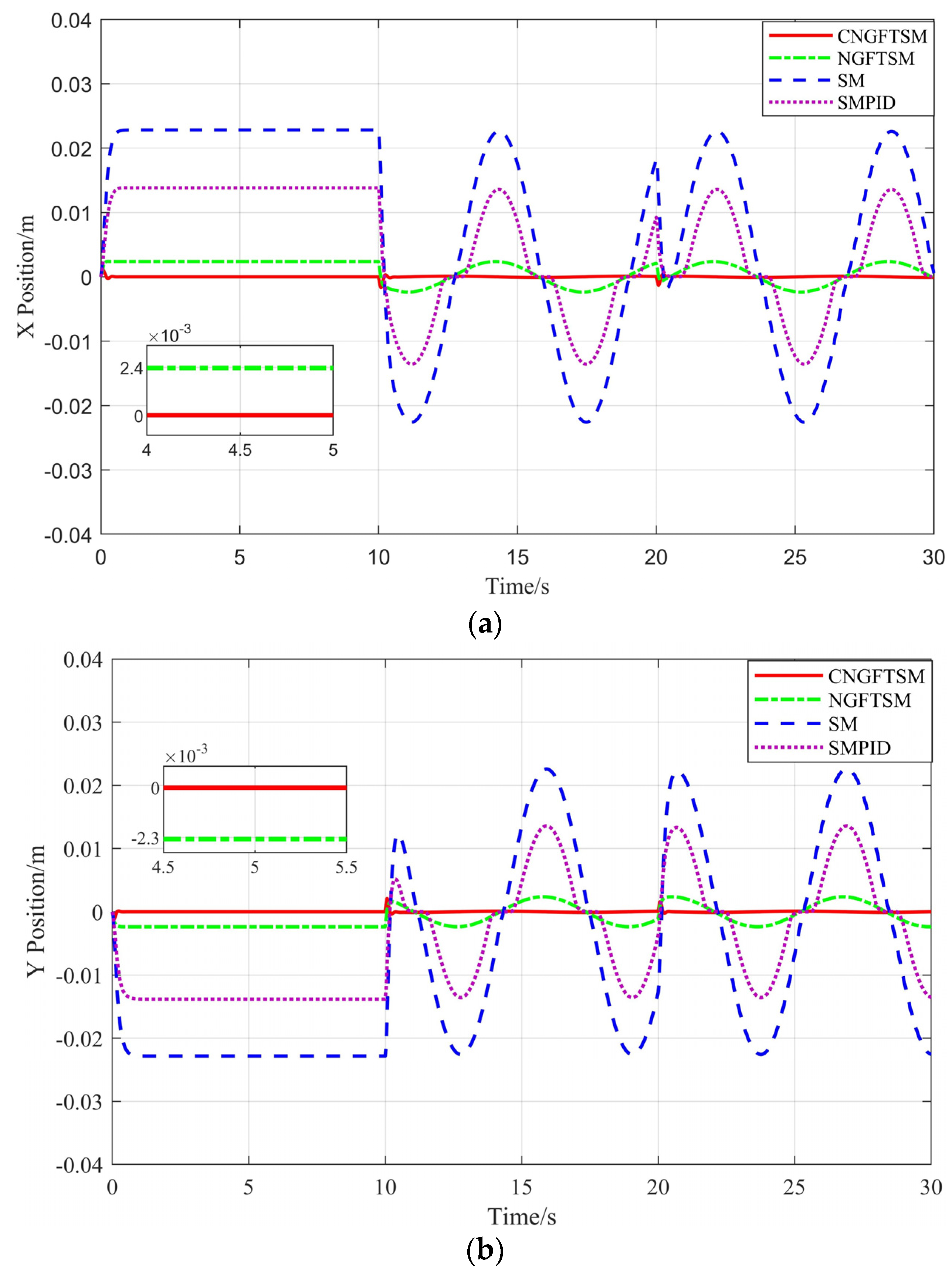
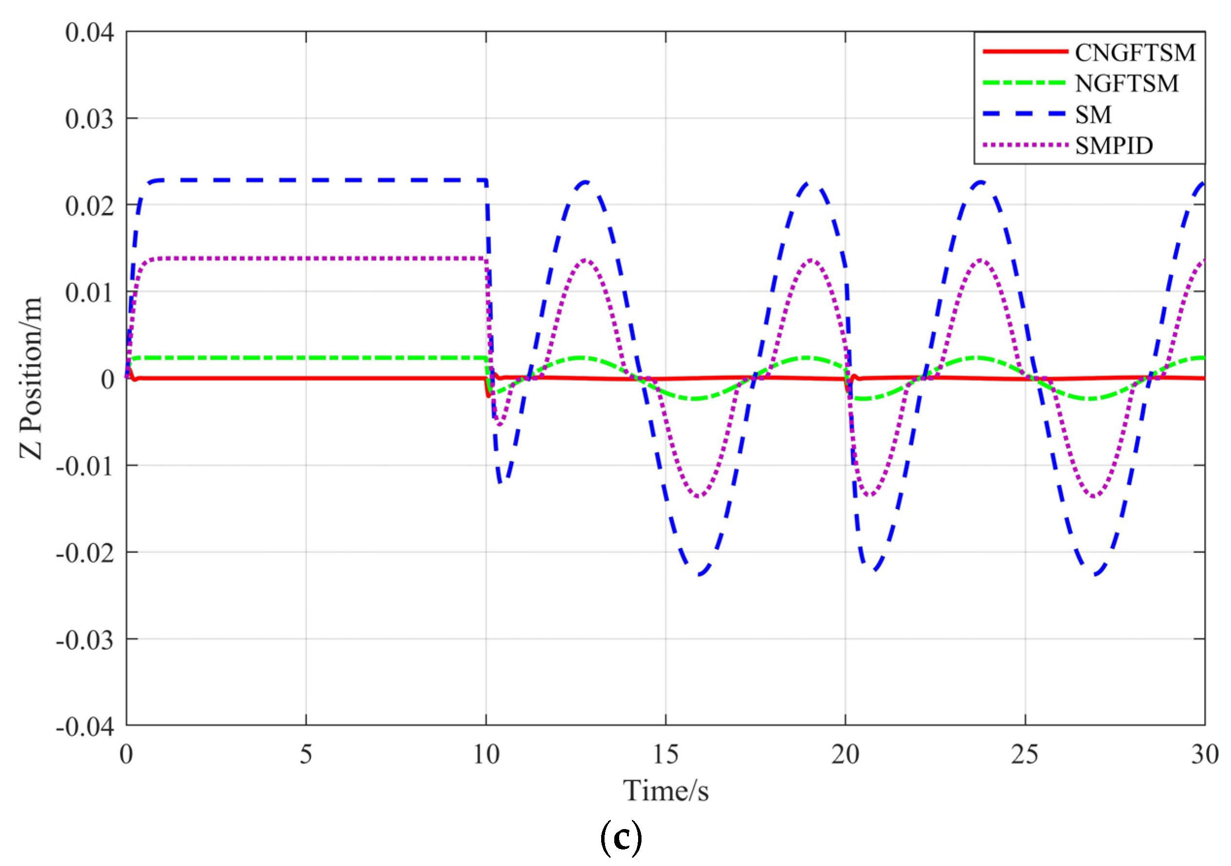
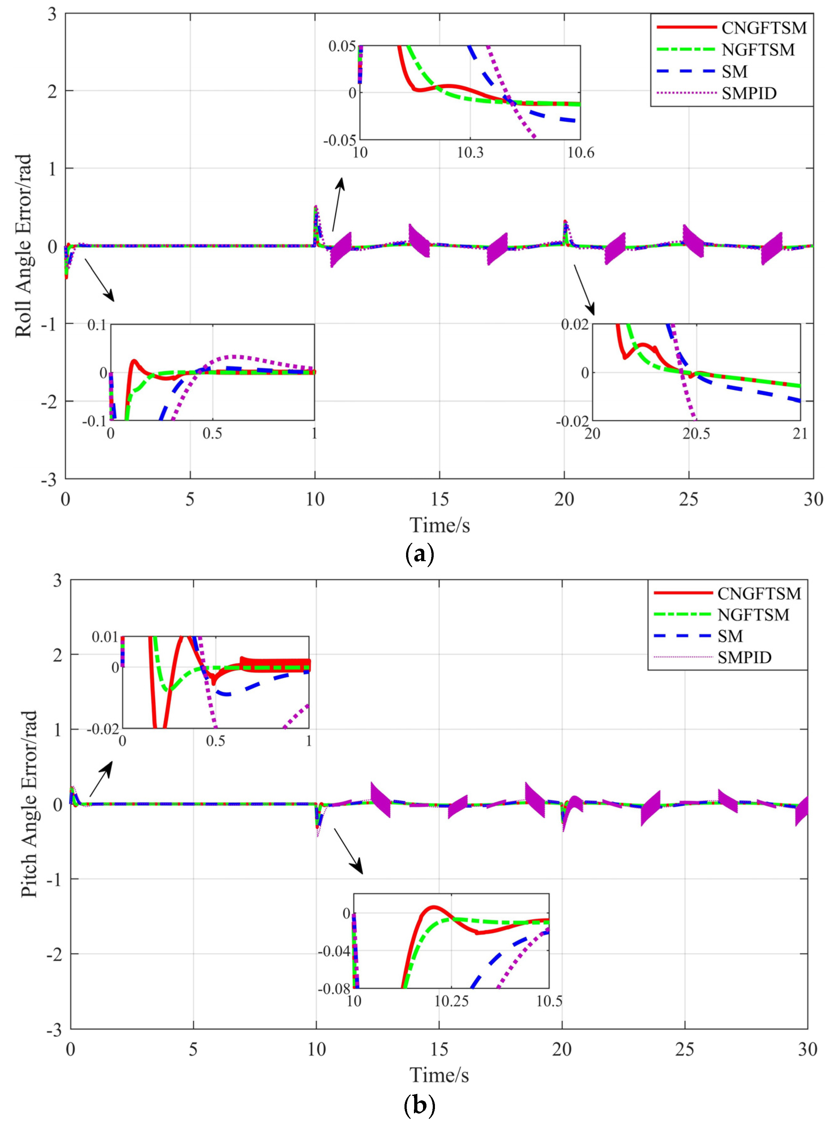
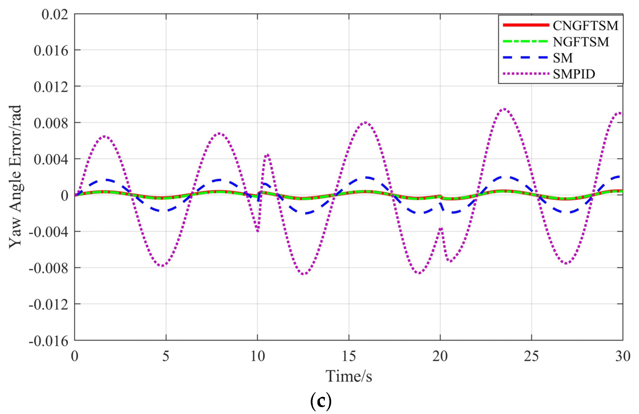
The system continues hovering at the initial position (0, 0, 0). As shown in Figure 3, because the static disturbances occur within 0–10 s, the steady-state errors of NGFTSM, SM and SMPID controllers are more than 0.002 m, 0.02 m and 0.01 m in the x , y and z directions, respectively. Similarly, the errors of NGFTSM, SM and SMPID controllers change continuously within 10–30 s due to the dynamic disturbances. In contrast, the errors of the proposed CNGFTSM controller are nearly zero throughout the process. In addition, the average convergence times for CNGFTSM, NGFTSM, SM and SMPID to reach the steady-state error in the x , y and z directions are about 0.45 s, 0.35 s, 0.95 s and 0.91 s, respectively. Figure 4 shows the error curves between the desired system and the actual attitude under the four control methods. The attitude tracking errors of the four controllers are minor with unchanged disturbances, whereas the roll and pitch angle curves of SMPID appear to oscillate when the disturbances change. However, the UAV motor is a mechanical device, and excessive changes in the amplitude of speed will produce considerable heat and violent vibration, eventually leading to mechanical failure. Therefore, vibration of the SMPID controller is not conducive to the mechanical characteristics of UAVs.

5.2. Square Trajectory Tracking

The expected square trajectory is as follows:
( x d , y d , z d ) = { ( 0 , 0 , 0 ) ( 0 , 0 , 5 ) ( 0 , 5 , 5 ) ( 5 , 5 , 5 ) ( 5 , 0 , 5 ) ( 0 , 0 , 5 ) t 5 5 < t 10 10 < t 15 15 < t 20 20 < t 25 20 < t 30
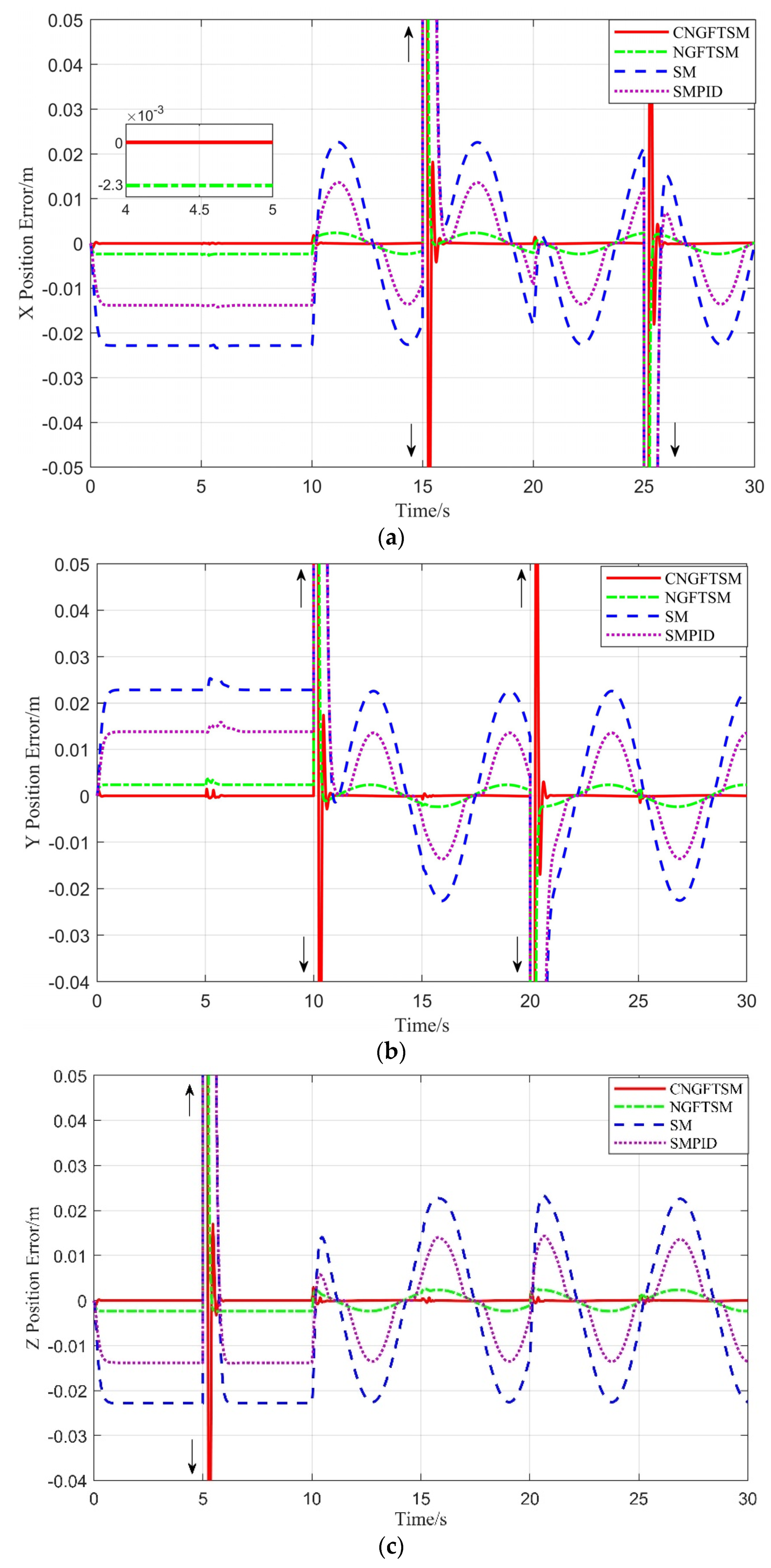
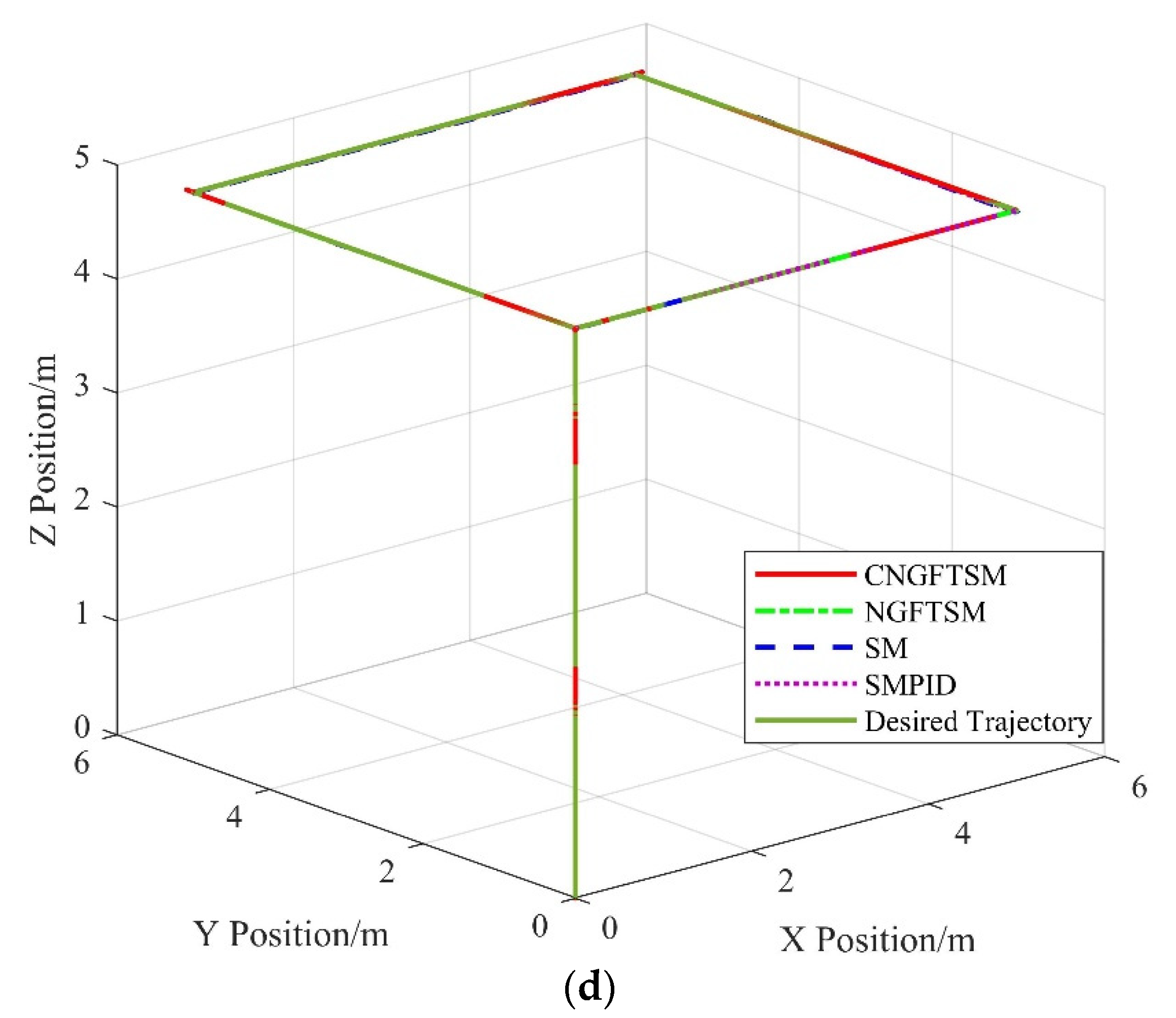
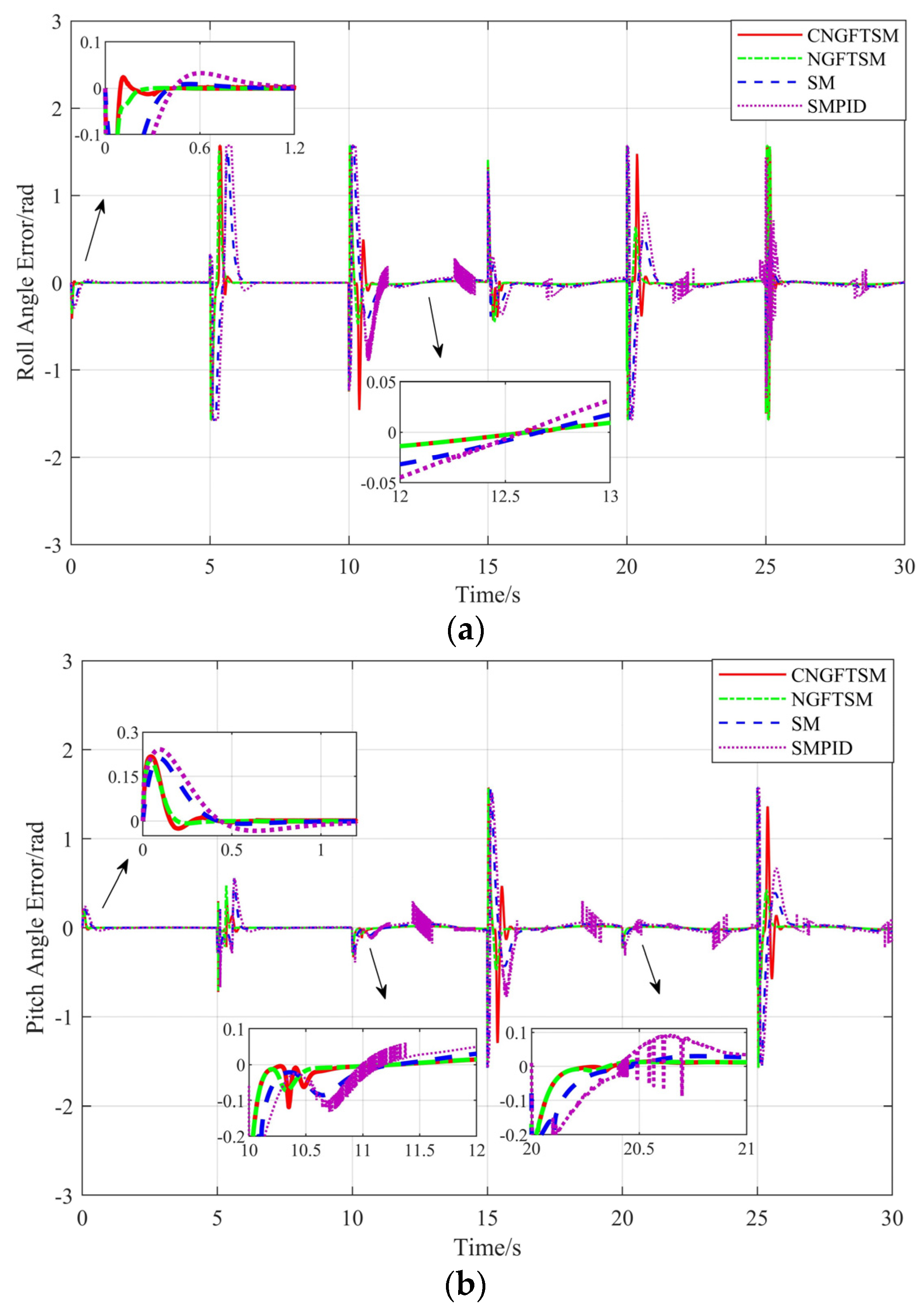
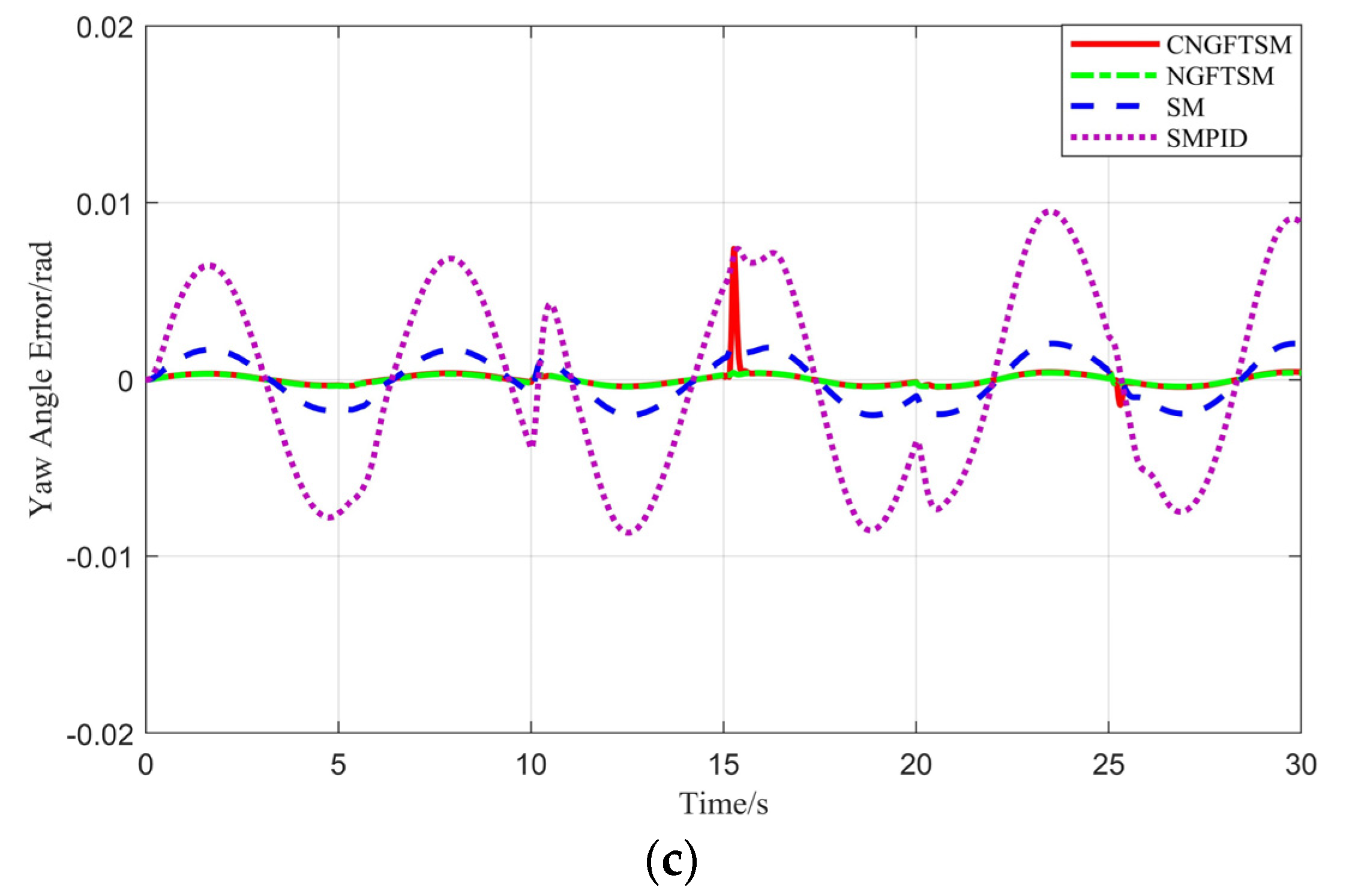
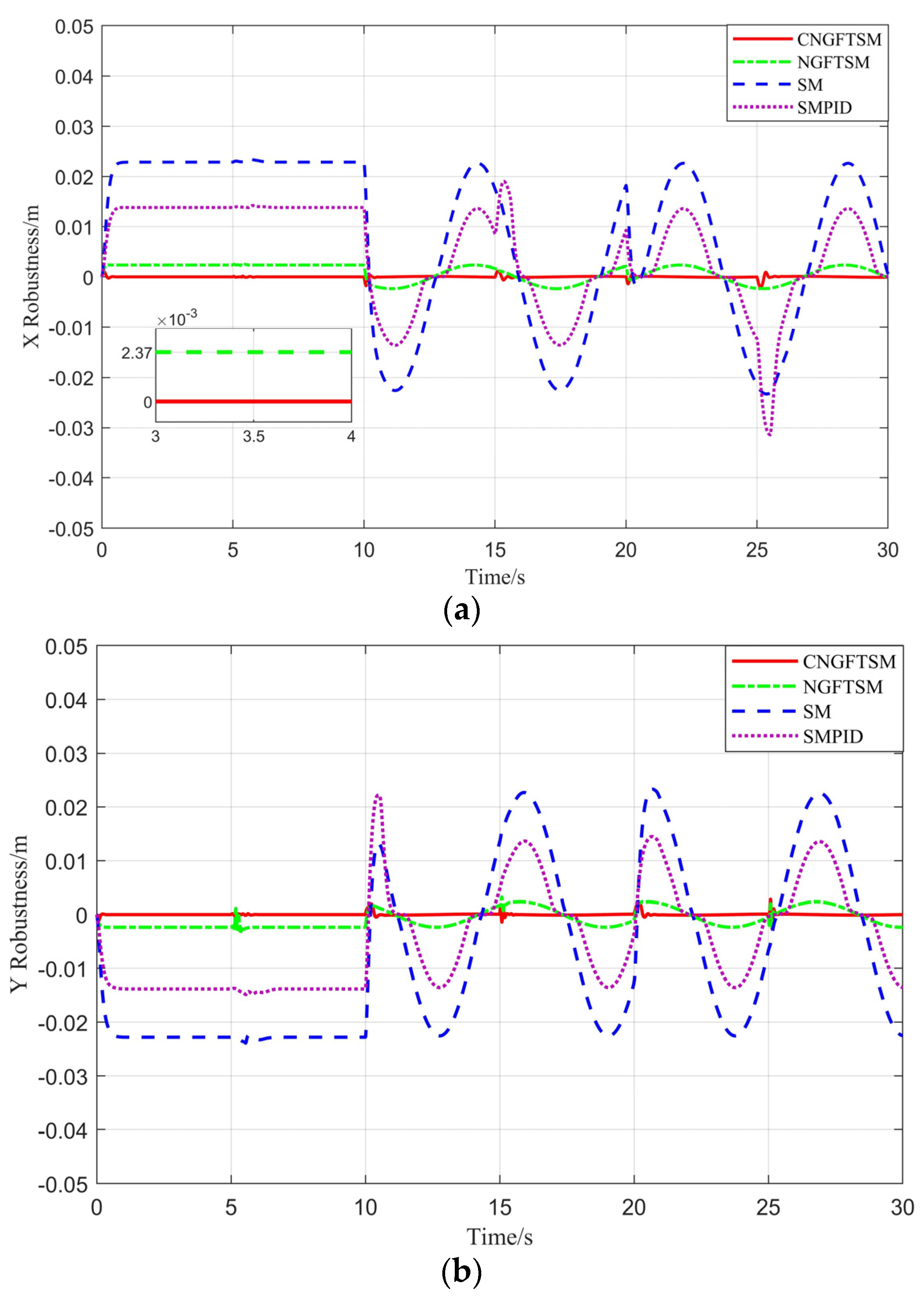
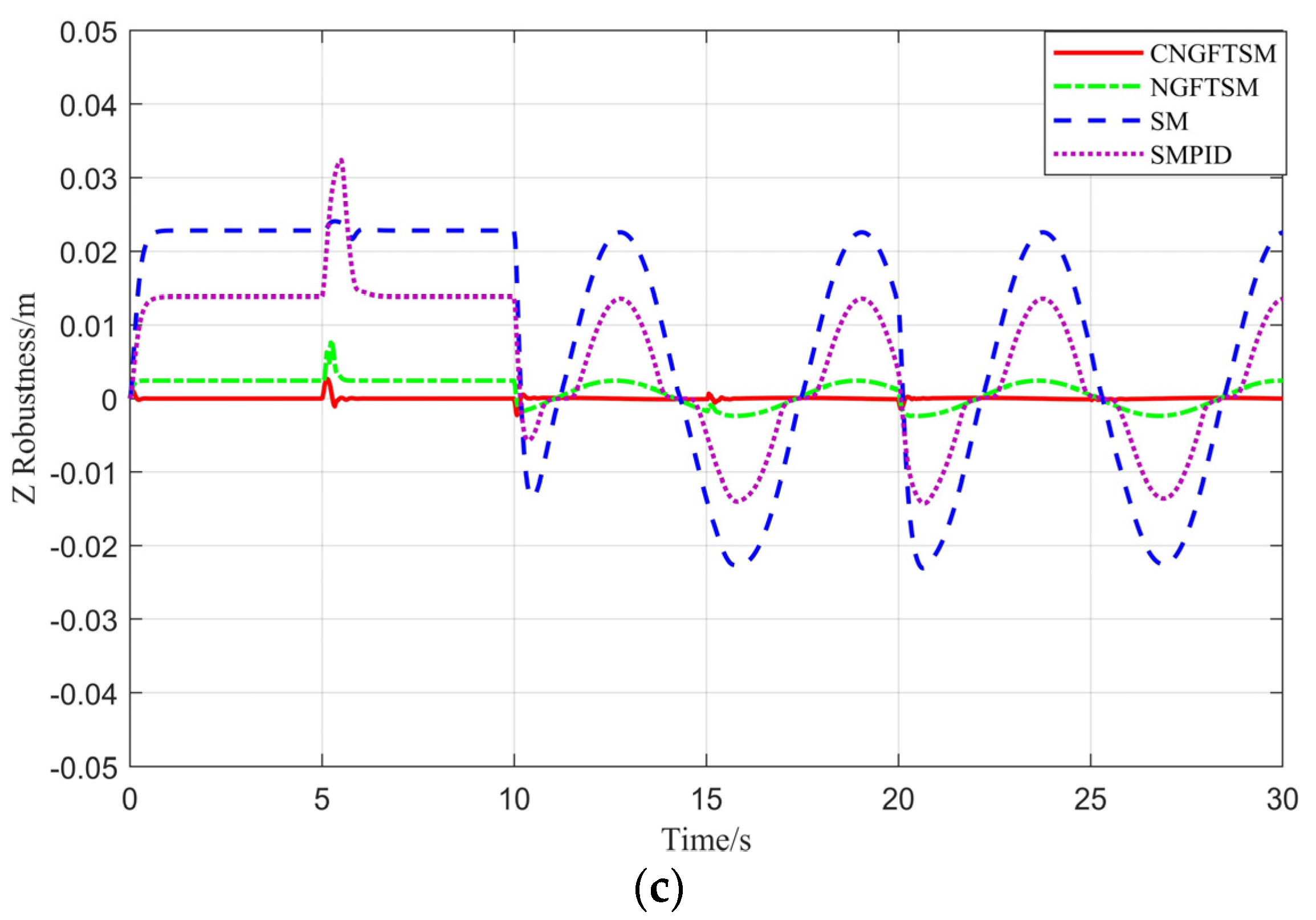
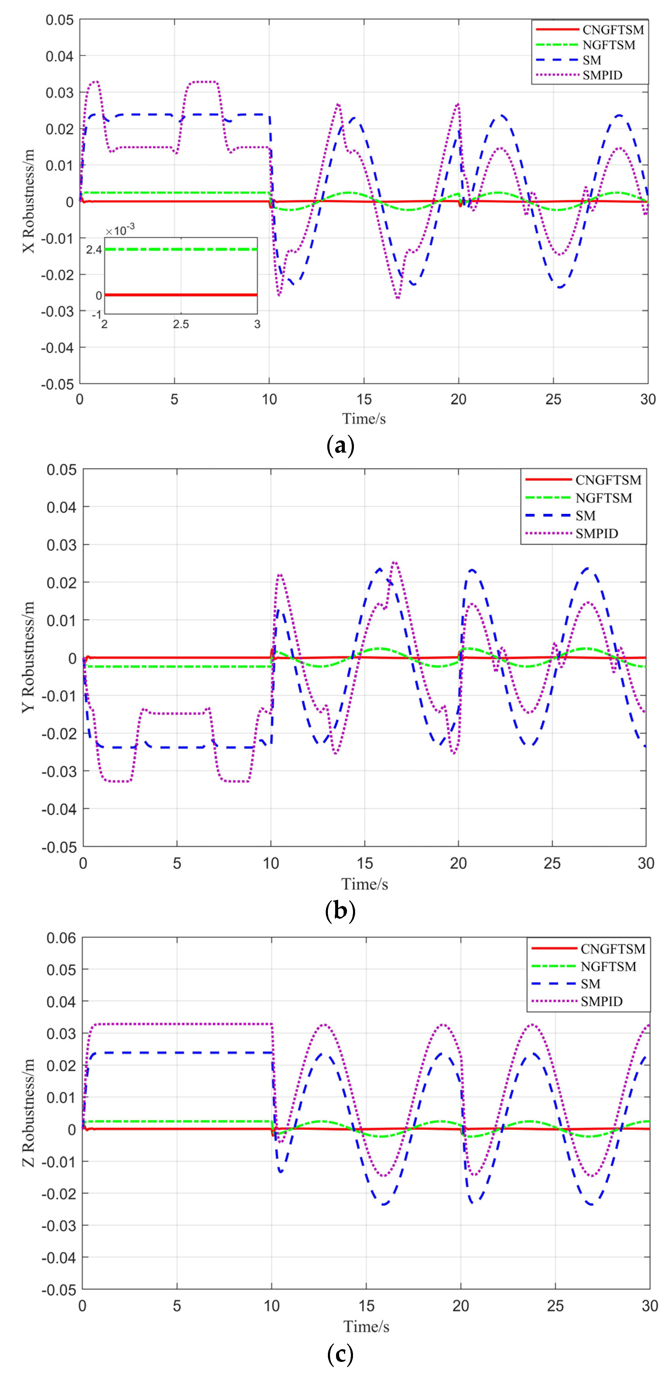
The overshoot part not shown in Figure 5 is 5 or −5. The systems using NGFTSM, SM and SMPID controllers have obvious steady-state errors compared with the using a CNGFTSM controller. The average convergence times for the four controllers to reach the steady-state error in the x , y and z directions are about 0.45 s, 0.36 s, 1.03 s and 0.94 s, respectively. As shown in Figure 5d, the actual flight trajectory of the system using the proposed controller almost coincides with the desired trajectory. Figure 6 shows the error curves between the desired system and actual the attitude under the four control methods. Similar to the results presented in Figure 4, the attitude tracking errors of the four controllers are minor in the 0–10 s range, whereas the controller SMPID oscillates in the 10–30 s range, possibly damaging the system’s mechanical characteristics. To evaluate the robustness of the four controllers, we subtract the result with disturbance from the result without disturbance, as shown in Figure 7. With the excepting the robust error of CNGFTSM, which is almost zero, the other controllers have obvious robust errors in the x , y and z directions, with average values of 0.002 m, 0.023 m and 0.014 m, respectively.

5.3. Spiral Trajectory Tracking

The expected spiral trajectory of the UAM system is x d = 0.5 sin ( t ) , y d = 0.5 cos ( t ) and z d = 0.5 t .
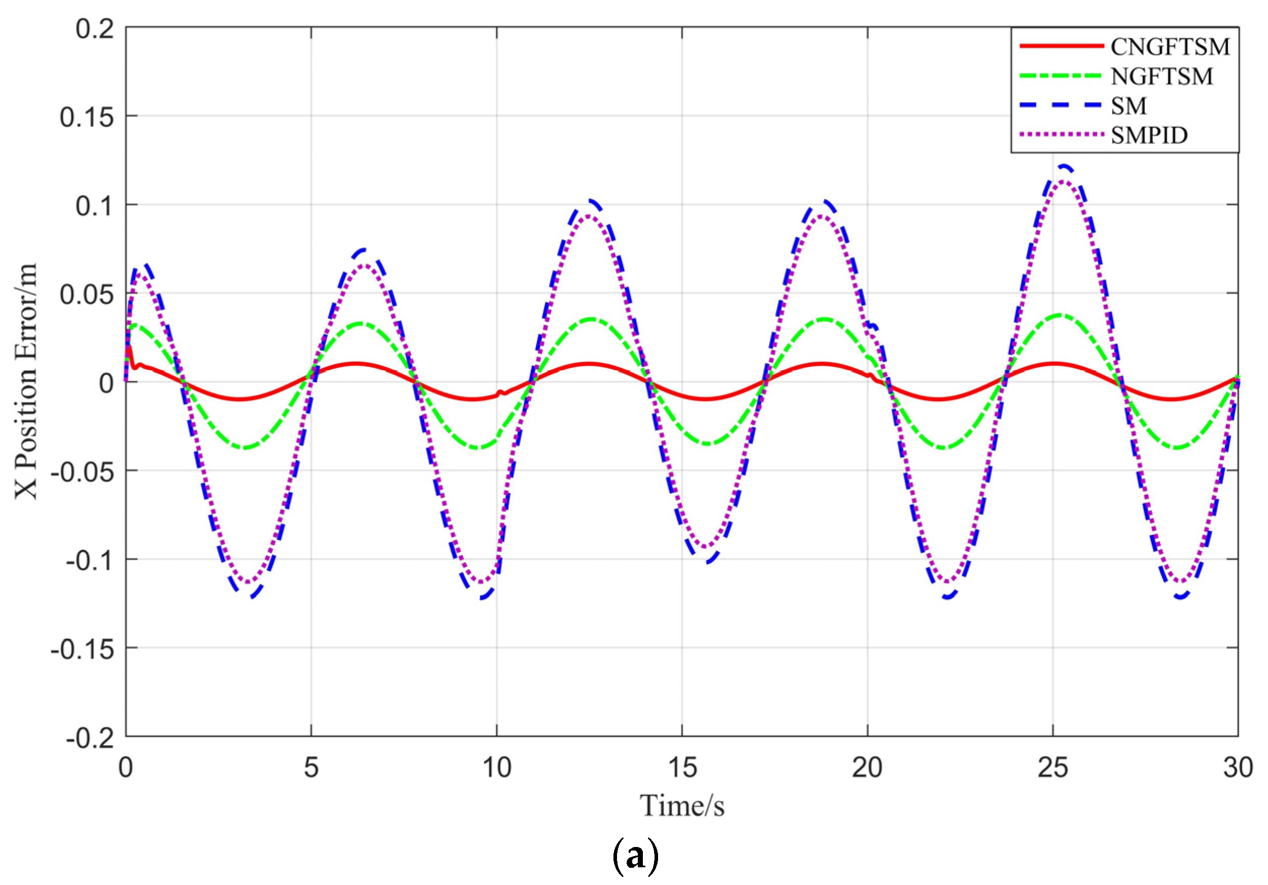
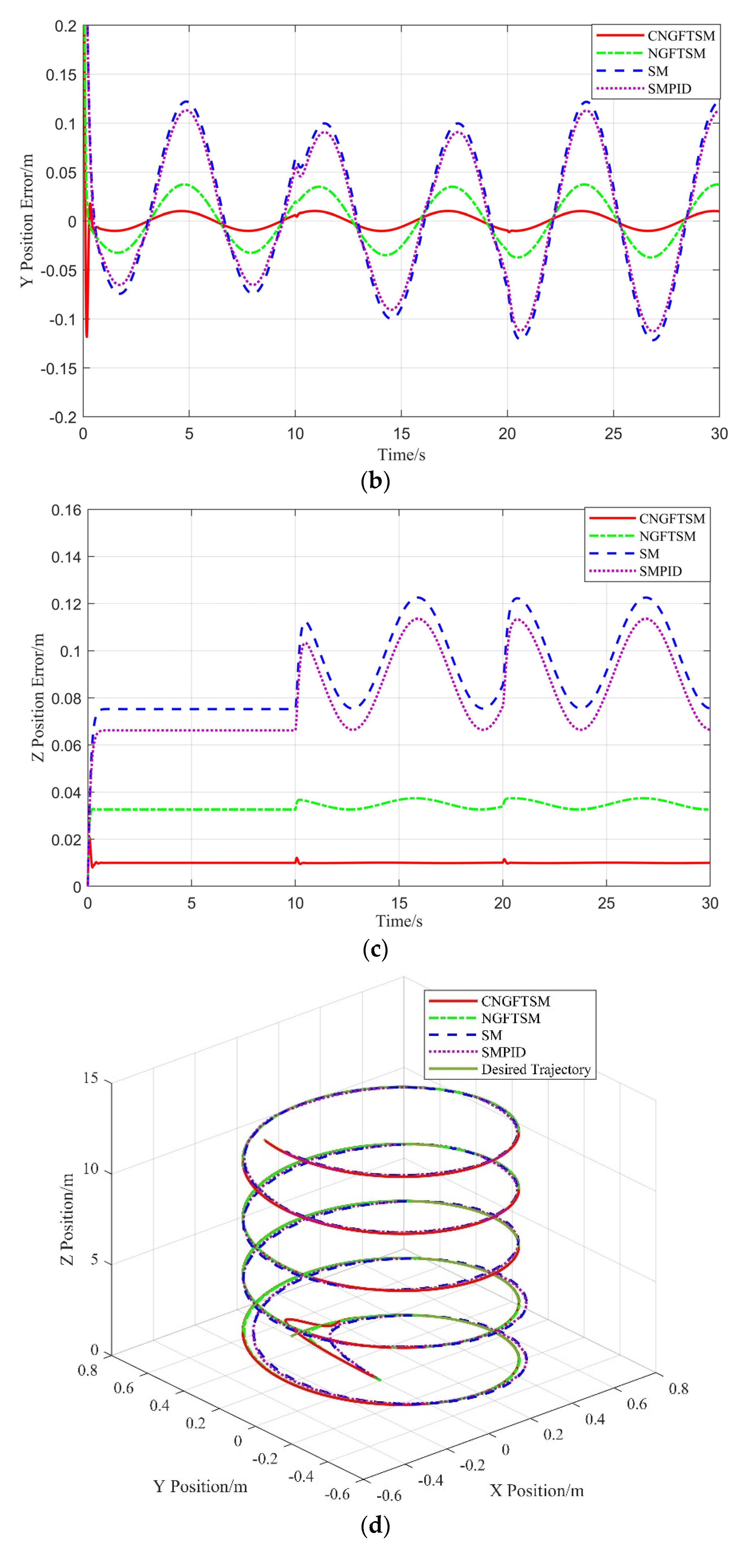
As shown in Figure 8, in the x and y directions, the maximum errors of the CNGFTSM both are both 0.010 m; the NGFTSM errors in the x and y directions are 0.032 m and 0.038 m, respectively; those of SM are both 0.122 m; and those of SMPID are both are 0.113 m. In the z direction, the time required to reach the steady-state error are 0.46 s, 0.36 s, 0.76 s and 0.79 s, and the maximum errors are 0.01 m, 0.037 m, 0.123 m and 0.113 m, for the CNGFTSM, NGFTSM, SM and SMPID controllers, respectively. Figure 8d shows the actual and desired trajectory of the system. Owing to the estimation and compensation of the RBF neural network, the position control accuracy of CNGFTSM is improved by more than 300% compared with NGFTSM. Figure 9 and Figure 10 show the attitude and robustness error curves of the four controllers. Similar to the previous experimental results, the attitude tracking errors are minor, with the exception of those of the SMPID controller, and controllers have obvious and continuously varying robust errors in the three directions, with the exception of the proposed controller. The simulation results are shown in Table 3, Table 4 and Table 5.
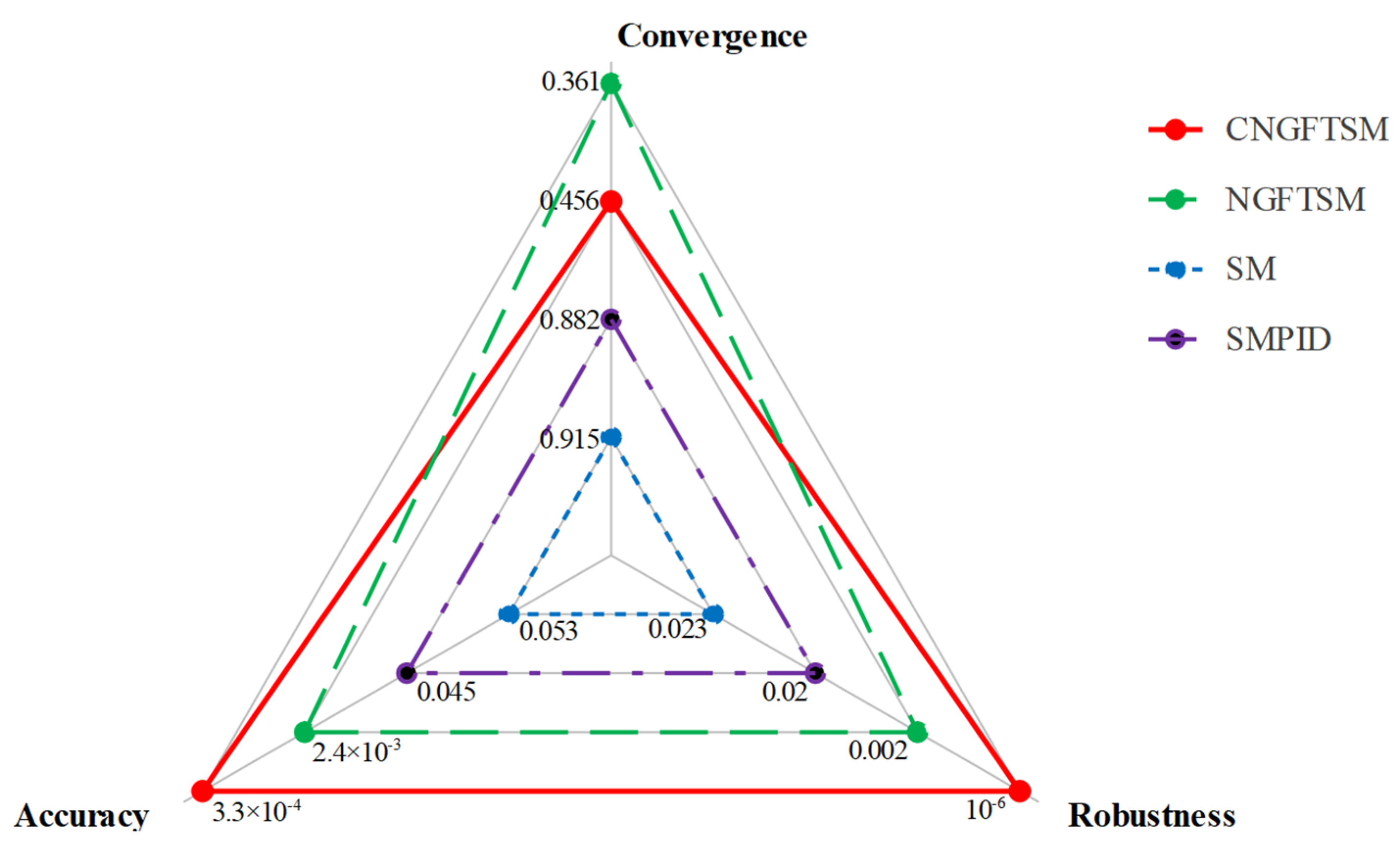
According to the results presented in Table 3, Table 4 and Table 5, the robustness and precision errors of the CNGFTSM controller are considerably less than 0.001 m, meeting the requirements of robustness and accuracy. On the contrary, NGFTSM only meets the robustness requirement, and SM and SMPID meet neither the robustness nor the accuracy requirements. The average errors of each term based on the simulation results are shown in Figure 11 for a comprehensive comparison of the controllers; the outer position line indicates a better ability. With the addition of a neural network module, the CNGFTSM convergence is slightly slower than that of the NGFTSM controller. Therefore, the CNGFTSM controller is suitable for applications with anti-disturbance and high-precision requirements. On the contrary, the NGFTSM controller is appropriate for applications requiring rapid response. In the next stage, we attempt to improve the convergence performance using neural networks to replace part of the model information to reduce computation requirements.
In summary, the CNGFTSM controller achieved the best performance, followed by the NGFTSM, SM and SMPID controllers. Moreover, a comparison of the NGFTSM controller with SM and SMPID controllers, reveals that the proposed nonsingular global fast terminal sliding mode has anti-disturbance ability, meeting the requirements of a fast variable system. Although we do not propose evaluation criteria for the RBF neural network, it has excellent compensation ability is robust according to a comparison the CNGFTSM and NGFTSM simulation results.

6. Experimental Results

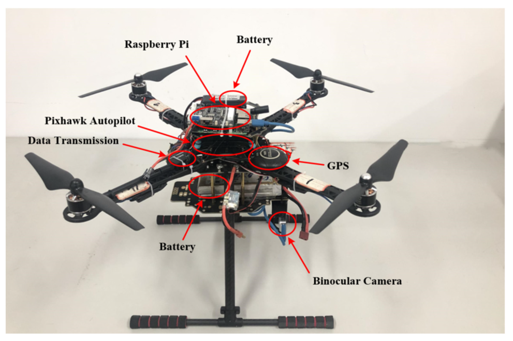
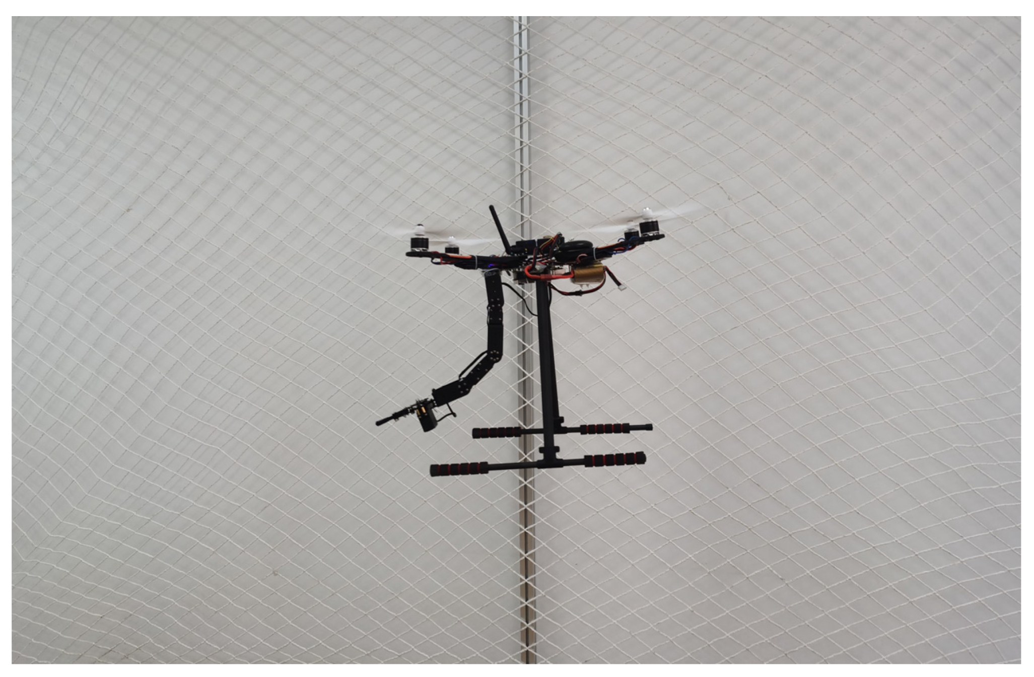
In this section, an experimental flight test of the aerial manipulator is carried out using the proposed control strategy. The quadrotor used in the experiment is shown in Figure 12, and the aerial manipulator used in the experiment is shown in Figure 13, consisting of a quadrotor and a manipulator. The quadrotor is equipped with 12-inch propellers, with a total diameter of 500 mm. It uses a Pixhawk autopilot board for low-level control of the quadrotor and a Raspberry Pi computer to run the control algorithm. The robotic arm is installed at the bottom of the quadrotor, consisting of a three-degrees-of-freedom robotic arm and a manipulator gripper; the battery is located opposite to the robotic arm to avoid the center of gravity leaning too far forward.
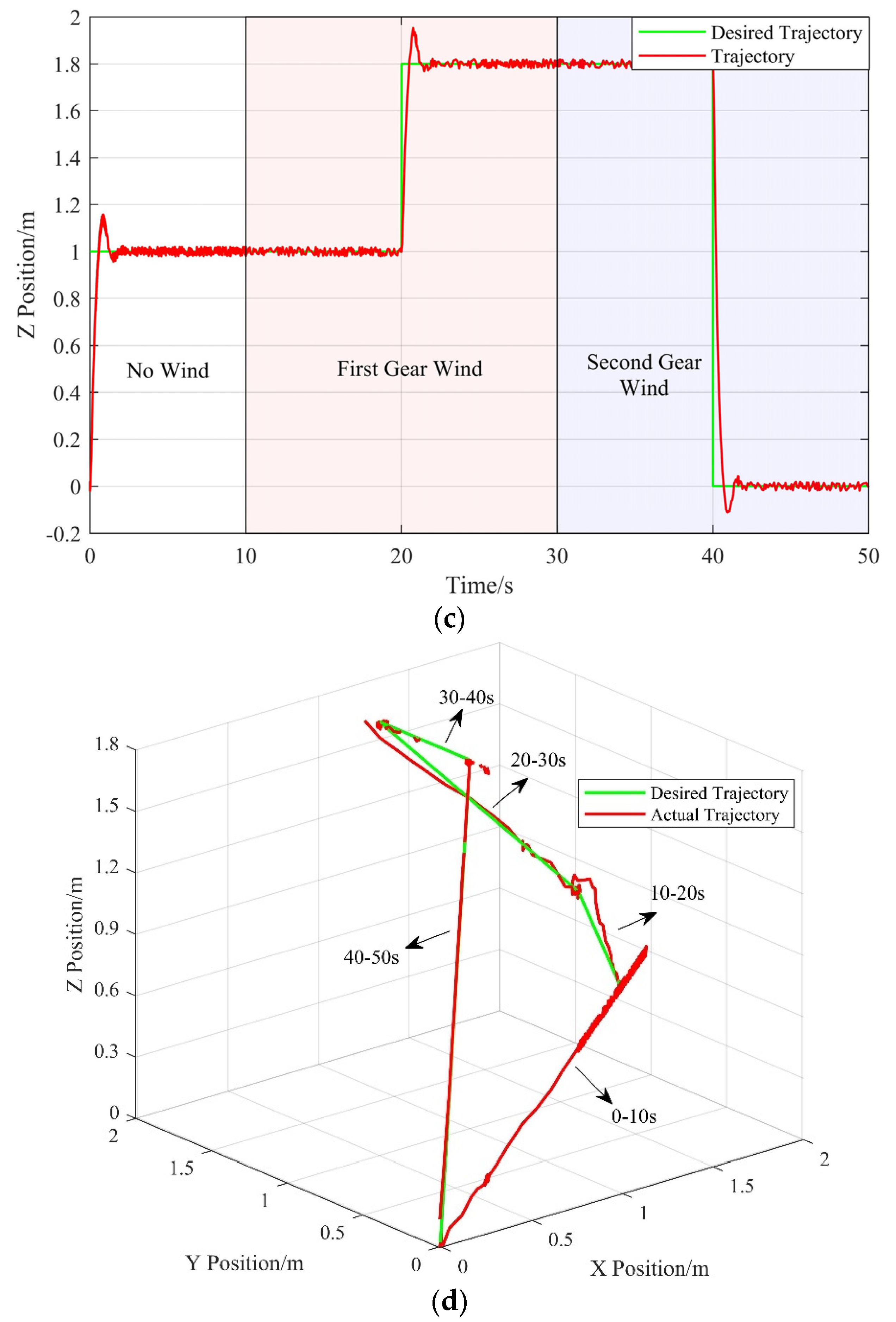
In the experiment, we place a fan to generate two levels of external disturbances corresponding to two levels of wind. After the quadrotor is armed under the manual control, autopilot is enabled. The expected height is 1.8 m. When the aerial manipulator reaches the desired height, a polygon trajectory is used as the expected trajectory for tracking. Figure 13 shows the position of the aerial manipulator in the trajectory tracking experiment. The average errors in the x , y and z directions are less 0.02 m, and the convergence times are about 0.55 s. The actual trajectory can closely track the desired trajectory, and the tracking errors are almost unchanged under the influence of external disturbances, changing from zero to the first-gear wind to the second-gear wind. Therefore, the system using the proposed controller achieves staisfactory response with minor trajectory tracking errors, fulfilling our requirements. The flight test results are shown in Figure 14.
7. Conclusions

In this paper, we propose a robust composite controller based on the nonsingular global fast terminal sliding mode and an RBF neural network for UAM trajectory tracking under the influence of disturbances. Several trajectory tracking simulations were carried out to evaluate the capabilities of the proposed controller. A comparison of the results of the NGFTSM controller with those of the SM and SMPID controller demonstrates that the proposed sliding mode function can effectively improve the convergence and precision of a UAM. A comparison of the results of the CNGFTSM controller with those of the NGFTSM controller proves that the designed RBF neural network has excellent estimation and compensation capabilities, significantly strengthening the system’s robustness. Furthermore, the UAM system using the CNGFTSM controller performs the trajectory tracking task with less oscillation than the other controller systems. The trajectory tracking experiment confirms the effectiveness of the proposed controller for application in aerial manipulator systems. However, with the addition of a neural network module, the CNGFTSM convergence is slightly slower than that of the NGFTSM controller, which can be improved by using neural networks instead of part of the model information to reduce computation in the future. Furthermore, we will further investigate anti-disturbance control of aerial manipulators for addition aerial tasks in future research.

Author Contributions

Methodology, L.S.; software, L.S. and Q.F.; validation, L.S., Q.F. and P.M.; data curation, L.S.; writing—original draft preparation, L.S.; writing—review and editing, L.S. and J.W.; visualization, P.M.; supervision, J.W. All authors have read and agreed to the published version of the manuscript.

Funding

This research was funded by the Major Program for Science and Technology of Henan (181100110100) and the Major Program for Science and Technology of Luoyang (2101018A).

Institutional Review Board Statement

Not applicable.

Informed Consent Statement

This work does not include any studies with human participants.

Data Availability Statement

The data used to support the findings of this study are included within the article.

Conflicts of Interest

The authors declare no conflict of interest.

Abbreviations

The following abbreviations are used in this manuscript:
UAVUnmanned aerial vehicle
UAMUnmanned aerial manipulation
RBFRadial basis function
CNGFTSMComposite nonsingular global fast terminal sliding mode
NGFTSMNonsingular global fast terminal sliding mode
SMSliding mode
SMPIDSliding Mode proportional-integral-derivative

References

  1. Wopereis, H.W.; Hoekstra, J.J.; Post, T.H.; Folkertsma, G.A.; Stramigioli, S.; Fumagalli, M. Application of substantial and sustained force to vertical surfaces using a quadrotor. In Proceedings of the 2017 IEEE International Conference on Robotics and Automation (ICRA), Singapore, 29 May–3 June 2017. [Google Scholar]
  2. Eisenbeiss, H. A mini unmanned aerial vehicle (UAV): System overview and image acquisition. Int. Arch. Photogramm. Remote Sens. Spat. Inf. Sci. 2004, 36, 1–7. [Google Scholar]
  3. Scherer, J.; Yahyanejad, S.; Hayat, S.; Yanmaz, E.; Andre, T.; Khan, A.; Vukadinovic, V.; Bettstetter, C.; Hellwagner, H.; Rinner, B. An autonomous multi-UAV system for search and rescue. In Proceedings of the First Workshop on Micro Aerial Vehicle Networks, Systems, and Applications for Civilian Use, Florence, Italy, 18 May 2015. [Google Scholar]
  4. Lindner, G.; Schraml, K.; Mansberger, R.; Hübl, J. UAV monitoring and documentation of a large landslide. Appl. Geomat. 2016, 8, 1–11. [Google Scholar] [CrossRef]
  5. Yang, B.; He, Y.; Han, J.; Liu, G.; Wang, Z.; Zhang, G. Survey on aerial manipulator systems. Jiqiren/Robot 2015, 37, 628–640. [Google Scholar]
  6. Qi, J.; Song, D.; Shang, H.; Wang, N.; Hua, C.; Wu, C.; Qi, X.; Han, J. Search and rescue rotary-wing uav and its application to the lushan ms 7.0 earthquake. J. Field Robot. 2016, 33, 290–321. [Google Scholar] [CrossRef]
  7. Capitan, J.; Merino, L.; Ollero, A. Cooperative decision-making undur uncertainties for multi-target surveillance with multiples UAVs. J. Intell. Robot. Syst. 2016, 84, 371–386. [Google Scholar] [CrossRef]
  8. Chowdhury, D.; Sarkar, M.; Haider, M.Z.; Fattah, S.A.; Shahnaz, C. Design and implementation of a cyber-vigilance system for anti-terrorist drives based on an unmanned aerial vehicular networking signal jammer for specific territorial security. In Proceedings of the 2017 IEEE Region 10 Humanitarian Technology Conference (R10-HTC), Dhaka, Bangladesh, 21–23 December 2017. [Google Scholar]
  9. Zhang, G.; He, Y.; Dai, B.; Gu, F.; Yang, L.; Han, J.; Liu, G.; Qi, J. Grasp a moving target from the air: System & control of an aerial manipulator. In Proceedings of the 2018 IEEE International Conference on Robotics and Automation (ICRA), Brisbane, QLD, Australia, 21–25 May 2018. [Google Scholar]
  10. Gabrich, B.; Saldana, D.; Kumar, V.; Yim, M. A flying gripper based on cuboid modular robots. In Proceedings of the 2018 IEEE International Conference on Robotics and Automation (ICRA), Brisbane, Australia, 21–25 May 2018. [Google Scholar]
  11. Meng, X.; He, Y.; Han, J. Survey on aerial manipulator: System, modeling, and control. Robotica 2020, 38, 1288–1317. [Google Scholar] [CrossRef]
  12. Ikeda, T.; Yasui, S.; Fujihara, M.; Ohara, K.; Ashizawa, S.; Ichikawa, A.; Okino, A.; Oomichi, T.; Fukuda, T. Wall contact by octo-rotor UAV with one DoF manipulator for bridge inspection. In Proceedings of the 2017 IEEE/RSJ International Conference on Intelligent Robots and Systems (IROS), Vancouver, BC, Canada, 24–28 September 2017. [Google Scholar]
  13. Ikeda, T.; Minamiyama, S.; Yasui, S.; Ohara, K.; Ichikawa, A.; Ashizawa, S.; Okino, A.; Oomichi, T.; Fukuda, T. Stable camera position control of unmanned aerial vehicle with three-degree-of-freedom manipulator for visual test of bridge inspection. J. Field Robot. 2019, 36, 1212–1221. [Google Scholar] [CrossRef]
  14. Seo, H.; Kim, S.; Kim, H.J. Aerial grasping of cylindrical object using visual servoing based on stochastic model predictive control. In Proceedings of the 2017 IEEE International Conference on Robotics and Automation (ICRA), Singapore, 29 May–3 June 2017. [Google Scholar]
  15. Lunni, D.; Santamaria-Navarro, A.; Rossi, R.; Rocco, P.; Bascetta, L.; Andrade-Cetto, J. Nonlinear model predictive control for aerial manipulation. In Proceedings of the 2017 International Conference on Unmanned Aircraft Systems (ICUAS), Miami, FL, USA, 13–16 June 2017. [Google Scholar]
  16. Garimella, G.; Kobilarov, M. Towards model-predictive control for aerial pick-and-place. In Proceedings of the 2015 IEEE International Conference on Robotics and Automation (ICRA), Seattle, WA, USA, 26–30 May 2015. [Google Scholar]
  17. Lippiello, V.; Ruggiero, F. Cartesian impedance control of a UAV with a robotic arm. IFAC Proc. Vol. 2012, 45, 704–709. [Google Scholar] [CrossRef] [Green Version]
  18. Huber, F.; Kondak, K.; Krieger, K.; Sommer, D.; Schwarzbach, M.; Laiacker, M.; Kossyk, I.; Parusel, S.; Haddadin, S.; Albu-Schäffer, A. First analysis and experiments in aerial manipulation using fully actuated redundant robot arm. In Proceedings of the 2013 IEEE/RSJ International Conference on Intelligent Robots and Systems, Tokyo, Japan, 3–8 November 2013. [Google Scholar]
  19. Caccavale, F.; Giglio, G.; Muscio, G.; Pierri, F. Adaptive control for UAVs equipped with a robotic arm. IFAC Proc. Vol. 2014, 47, 11049–11054. [Google Scholar] [CrossRef] [Green Version]
  20. Lee, H.; Kim, H.J. Estimation, control, and planning for autonomous aerial transportation. IEEE Trans. Ind. Electron. 2016, 64, 3369–3379. [Google Scholar] [CrossRef]
  21. Kim, S.; Choi, S.; Kim, H.J. Aerial manipulation using a quadrotor with a two dof robotic arm. In Proceedings of the 2013 IEEE/RSJ International Conference on Intelligent Robots and Systems, Tokyo, Japan, 3–7 November 2013. [Google Scholar]
  22. Kim, S.; Seo, H.; Choi, S.; Kim, H.J. Vision-guided aerial manipulation using a multirotor with a robotic arm. IEEE/ASME Trans. Mechatron. 2016, 21, 1912–1923. [Google Scholar] [CrossRef]
  23. He, W.; Fang, Y.; Liang, X.; Zhang, P. Design and implementation of a 2-DOF aerial manipulation system. Acta Aeronaut. Astronaut. Sin. 2021, 42, 264–274. [Google Scholar]
  24. Bouzgou, K.; Benchikh, L.; Nouveliere, L.; Ahmed-Foitih, Z. PD sliding mode controller based decoupled aerial manipulation. In Proceedings of the 17th International Conference on Informatics in Control, Automation and Robotics (ICINCO 2020), Paris, France, 7–9 July 2020. [Google Scholar]
  25. Lin, X.; Wang, Y.; Liu, Y. Neural-network-based robust terminal sliding-mode control of quadrotor. Asian J. Control. 2022, 24, 427–438. [Google Scholar] [CrossRef]
  26. Mofid, O.; Mobayen, S.; Fekih, A. Adaptive integral-type terminal sliding mode control for unmanned aerial vehicle under model uncertainties and external disturbances. IEEE Access 2021, 9, 53255–53265. [Google Scholar] [CrossRef]
  27. Zhao, J.; Wang, Y.; Wang, D.; Ju, F.; Chen, B.; Wu, H. Practical continuous nonsingular terminal sliding mode control of a cable-driven manipulator developed for aerial robots. Proc. Inst. Mech. Eng. Part I J. Syst. Control. Eng. 2020, 234, 1011–1023. [Google Scholar] [CrossRef]
  28. Zhao, Z.; Xiao, L.; Jiang, B.; Cao, D. Fast nonsingular terminal sliding mode trajectory tracking control of a quadrotor UAV based on extended state observers. Control Decis. 2022, 37, 2201–2210. [Google Scholar]
  29. Phiboon, T.; Khankwa, K.; Petcharat, N.; Phoksombat, N.; Kanazaki, M.; Kishi, Y.; Bureerat, S.; Ariyarit, A. Experiment and computation multi-fidelity multi-objective airfoil design optimization of fixed-wing UAV. J. Mech. Sci. Technol. 2021, 35, 4065–4072. [Google Scholar] [CrossRef]
  30. Lee, J.; Bahri, Y.; Novak, R.; Schoenholz, S.S.; Pennington, J.; Sohl-Dickstein, J. Deep neural networks as gaussian processes. arXiv 2017, arXiv:1711.00165. [Google Scholar]
  31. Arleo, G.; Caccavale, F.; Muscio, G.; Pierri, F. Control of quadrotor aerial vehicles equipped with a robotic arm. In Proceedings of the 21st Mediterranean Conference on Control and Automation, Platanias, Greece, 25–28 June 2013. [Google Scholar]
Figure 1. Structure of the reference frames.
Machines 10 01021 g001
Figure 2. Aerial manipulator control framework.
Machines 10 01021 g002
Figure 3. The position error of the system. (a) Error in the x direction. (b) Error in the y direction. (c) Error in the z direction.
Machines 10 01021 g003aMachines 10 01021 g003b
Figure 4. Euler angle tracking error of the system. (a) Roll angle error. (b) Pitch angle error. (c) Yaw angle error.
Machines 10 01021 g004aMachines 10 01021 g004b
Figure 5. Square trajectory tracking error of the system. (a) Error in the x direction. (b) Error in the y direction. (c) Error in the z direction. (d) Actual and desired trajectory of the system with the designed controller.
Machines 10 01021 g005aMachines 10 01021 g005b
Figure 6. Euler angle tracking error of the square trajectory. (a) Roll angle error. (b) Pitch angle error. (c) Yaw angle error.
Machines 10 01021 g006aMachines 10 01021 g006b
Figure 7. The tracking error between the system with external disturbance and the system without external disturbance. (a) Error in the x direction. (b) Error in the y direction. (c) Error in the z direction.
Machines 10 01021 g007aMachines 10 01021 g007b
Figure 8. Spiral trajectory tracking error of the system. (a) Error in the x direction. (b) Error in the y direction. (c) Error in the z direction. (d) Actual and desired trajectory of the system.
Machines 10 01021 g008aMachines 10 01021 g008b
Figure 9. Euler angle tracking error of the spiral trajectory. (a) Roll angle error. (b) Pitch angle error. (c) Yaw angle error.
Machines 10 01021 g009
Figure 10. Tracking error between the system with external disturbance and the system without external disturbance. (a) Error in the x direction. (b) Error in the y direction. (c) Error in the z direction.
Machines 10 01021 g010
Figure 11. Comparison of the four controllers.
Machines 10 01021 g011
Figure 12. The quadrotor used in the experiment.
Machines 10 01021 g012
Figure 13. Aerial manipulator flight test.
Machines 10 01021 g013
Figure 14. Trajectory tracking experimental results. (a) Results in the x direction. (b) Results in the y direction. (c) Results in the z direction. (d) Desired and actual trajectory of the system.
Machines 10 01021 g014aMachines 10 01021 g014b
Table 1. Parameters of the aerial manipulator simulation.
ParameterValueParameterValueParameterValue
m 1.8 kg m 1 0.5 kg m 2 0.5 kg
I x x / ( kg m 2 ) 1.24 I x 1 / ( kg m 2 ) 10−3 I x 2 / ( kg m 2 ) 10−3
I y y / ( kg m 2 ) 1.24 I y 1 / ( kg m 2 ) 10−3 I y 2 / ( kg m 2 ) 10−3
I z z / ( kg m 2 ) 2.48 I z 1 / ( kg m 2 ) 0 I z 2 / ( kg m 2 ) 0
l 1 0.15 m l 2 0.15 m
Table 2. Parameters for NGFTSM function and the RBF neural network.
NGFTSM FunctionRBF Neural Network
ParameterValueParameterValue
Γ d i a g ( 50 , 50 , 50 ) c j 0.1 [ 1 0.5 0 0.5 1 1 0.5 0 0.5 1 ]
Λ d i a g ( 1 400 , 1 400 , 1 400 ) b j 5
λ d i a g ( 20 , , 20 ) δ p 0.01
η d i a g ( 0.01 , , 0.01 ) δ Φ 15
Table 3. The average convergence time in the x , y and z directions.
Convergence/sCNGFTSMNGFTSMSMSMPID
Simulation 10.4520.3540.9520.911
Simulation 20.4550.3651.0310.942
Simulation 30.4610.3630.7630.794
Table 4. The average steady-state error in the x , y and z directions.
Accuracy/mCNGFTSMNGFTSMSMSMPID
Simulation 110−60.0020.0230.014
Simulation 210−60.0020.0240.015
Simulation 30.0010.00320.1120.106
Table 5. The average robustness errors in the x , y and z directions.
Robustness/mCNGFTSMNGFTSMSMSMPID
Simulation 210−60.0020.0230.014
Simulation 310−60.0020.0230.025
Publisher’s Note: MDPI stays neutral with regard to jurisdictional claims in published maps and institutional affiliations.