


Analysis of Ball Check Valves with Conical and Spherical Seat Designs from Common-Rail Pumps


Abstract
1. Introduction
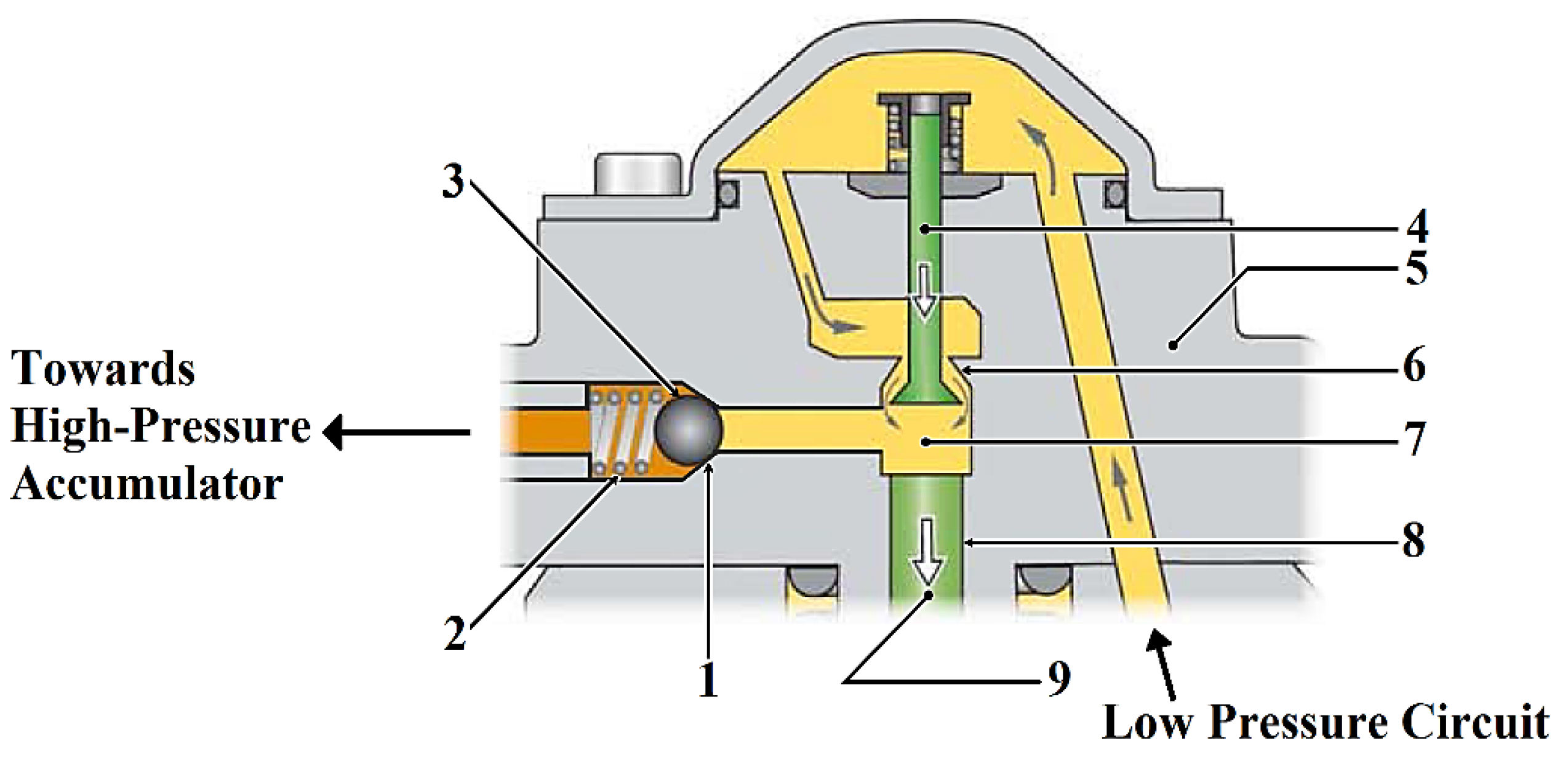
2. Hydraulic Head Assembly Components
3. Theoretical Analysis
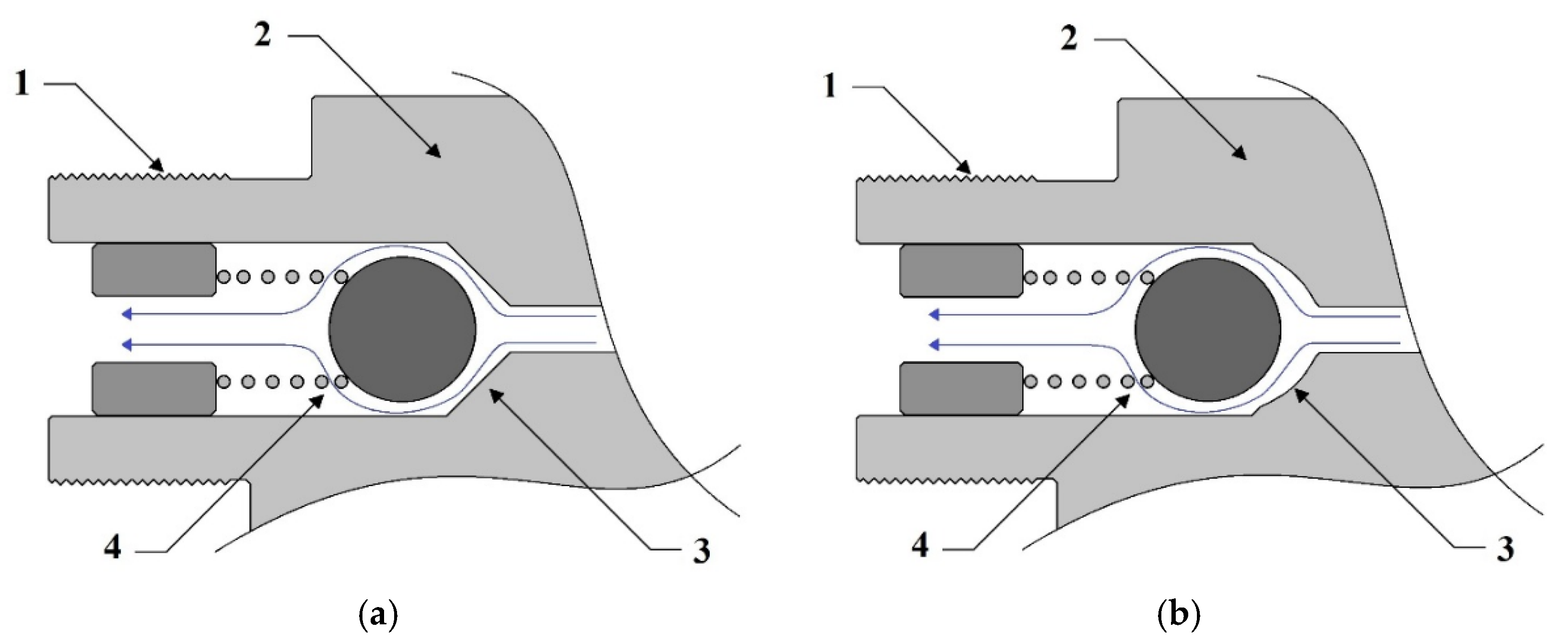
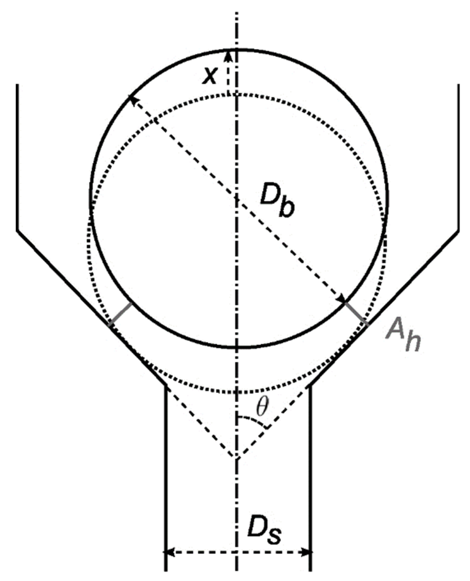
3.1. Simplified Ball Check Valve Modelling
- RPM—common-rail pump shaft speed;
- RPMmax—maximum speed of the common-rail pump shaft;
- xmax—maximum valve opening height (lift).
- dc—discharge coefficient;
- ∆p—difference between upstream and downstream pressure;
- —fluid density.
- pup—upstream pressure (before valve);
- pdn—downstream pressure (after valve);
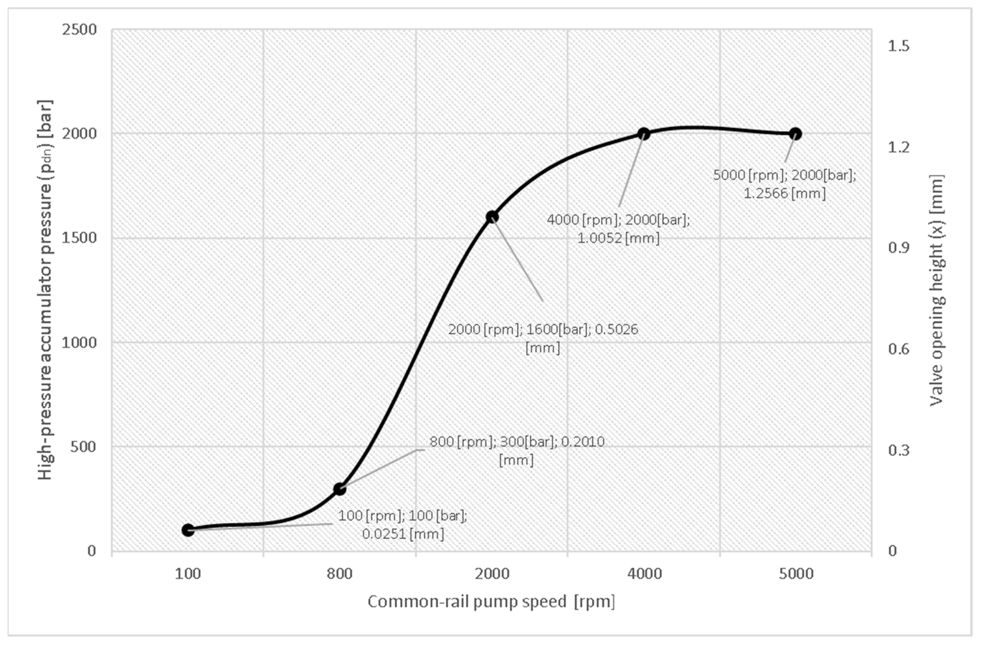
3.2. Theoretical Results
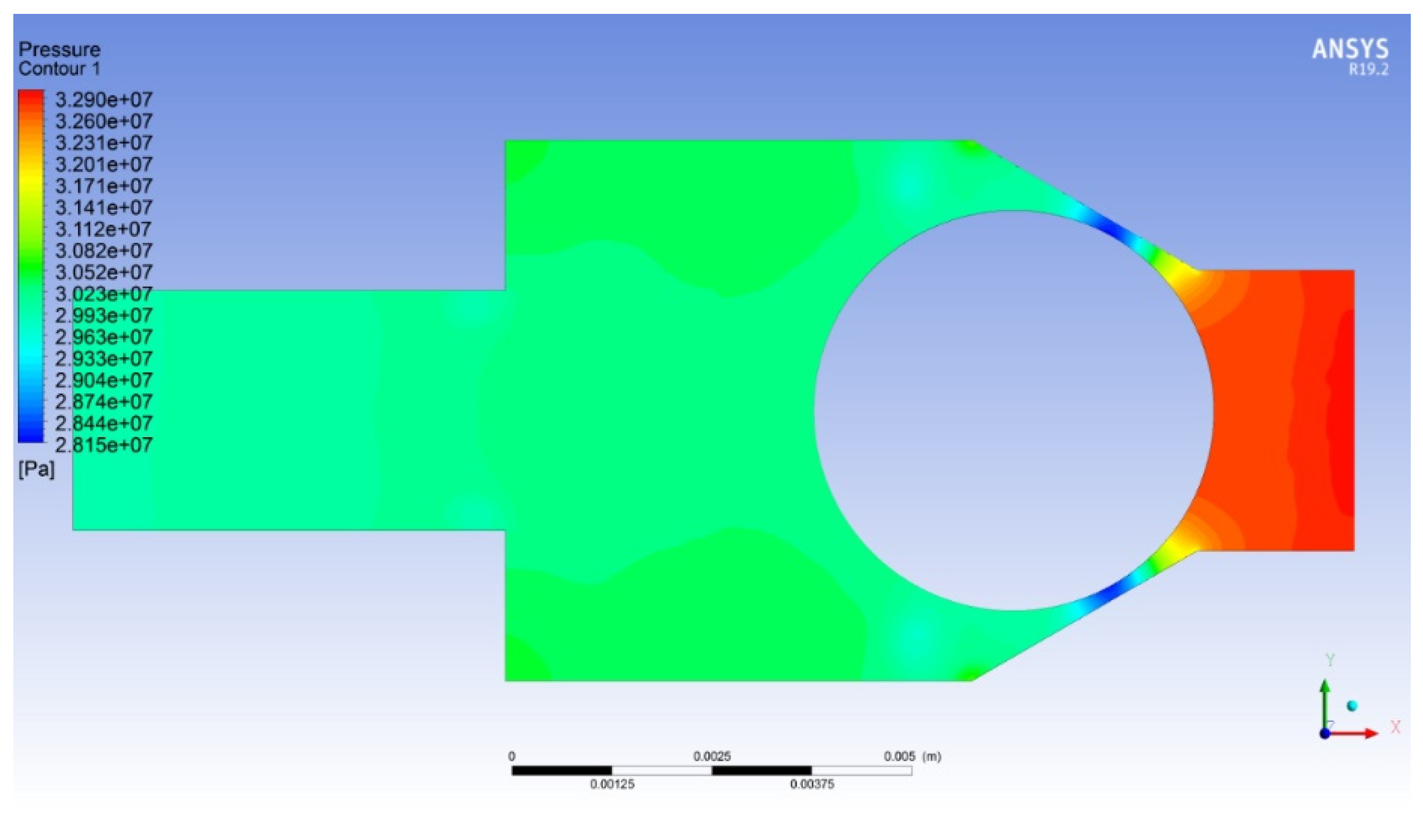
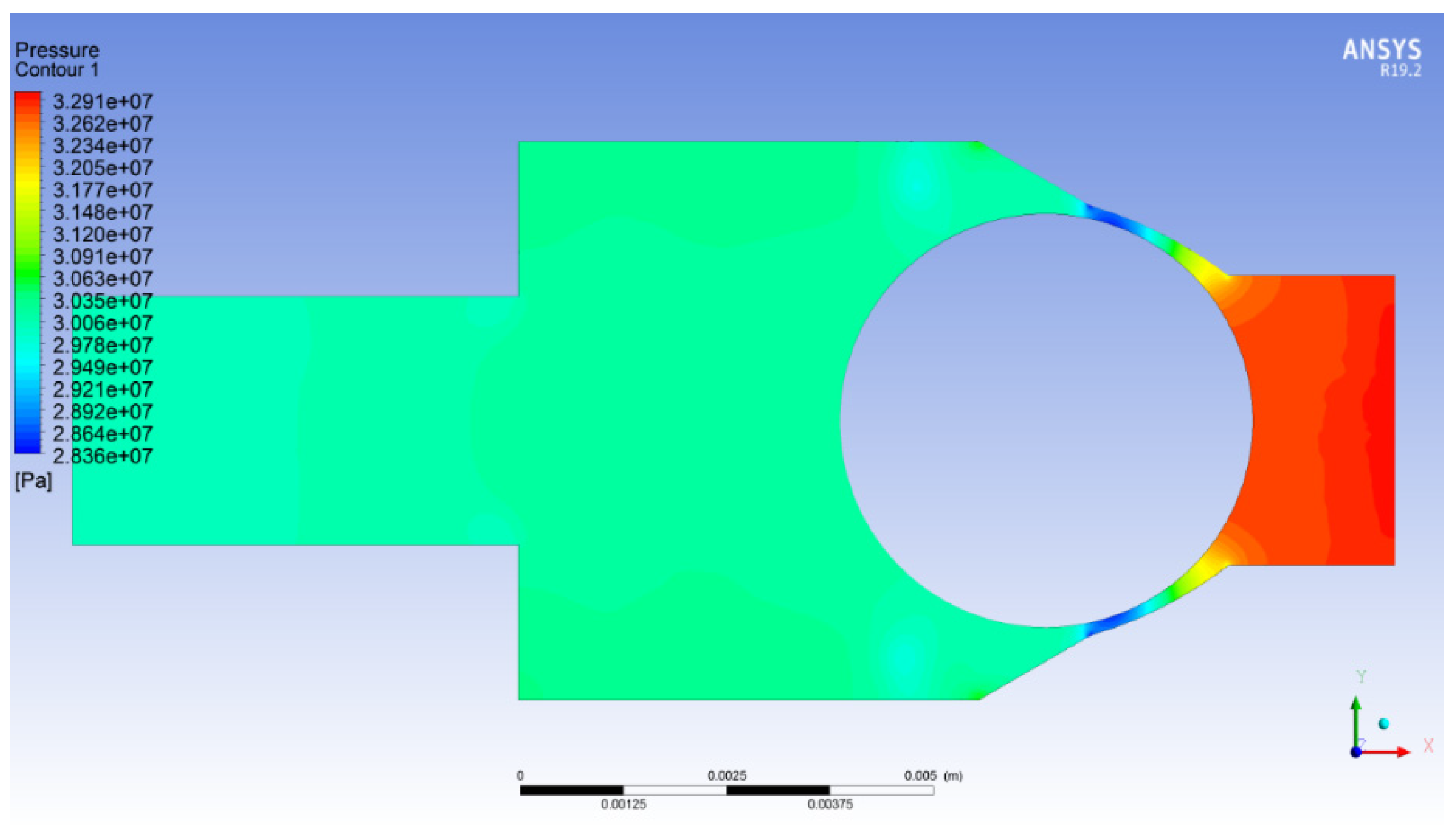
4. CFD Analysis
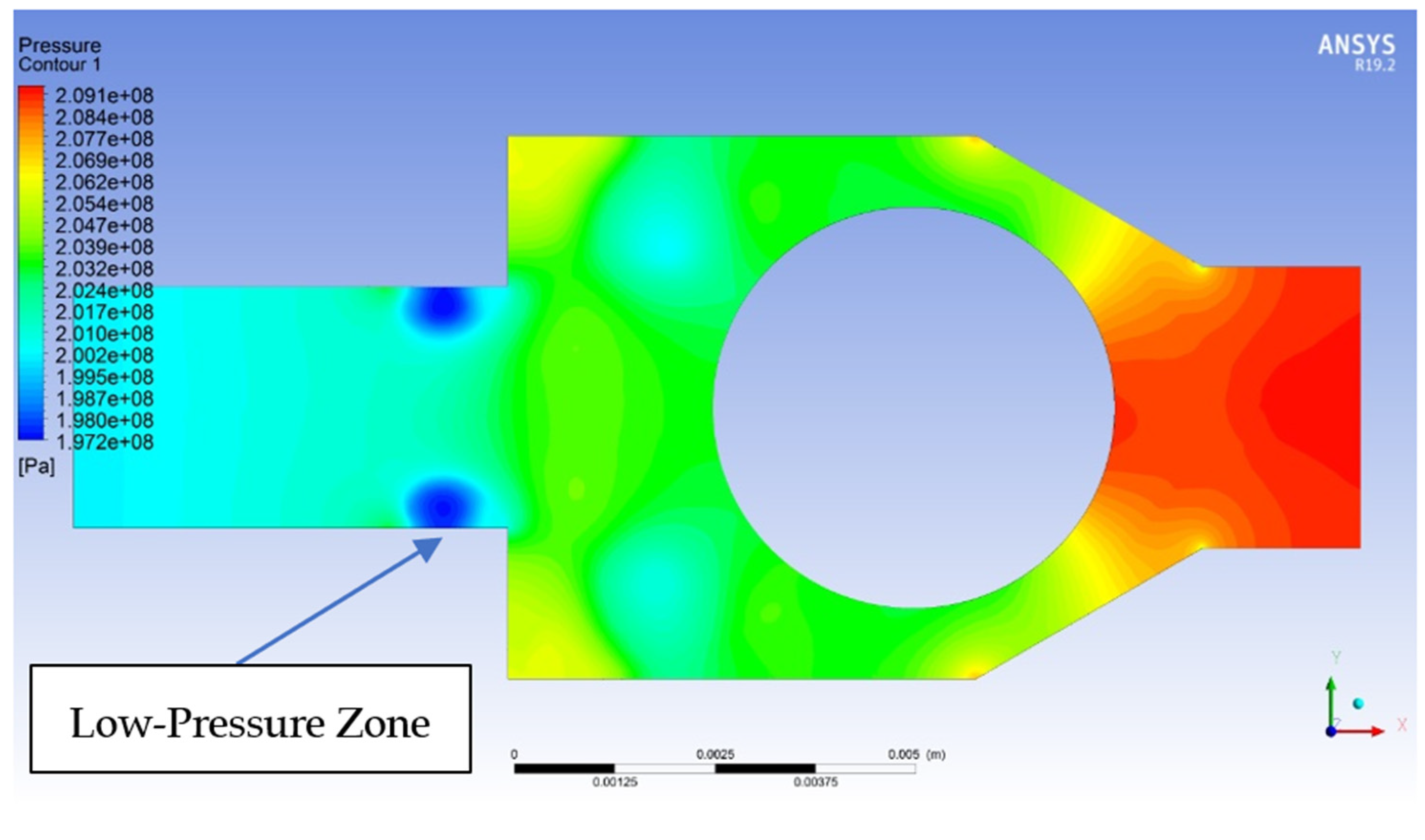
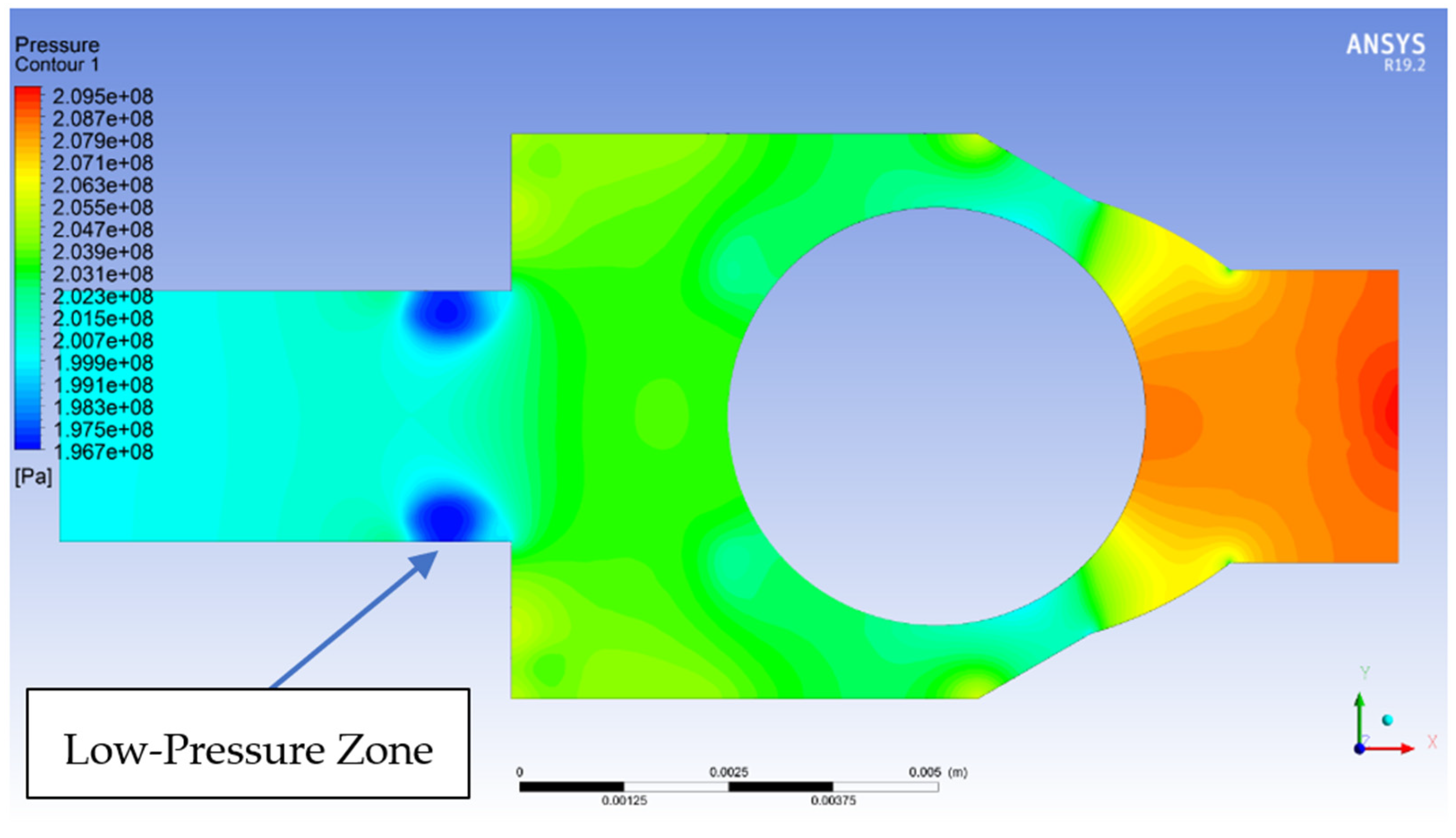
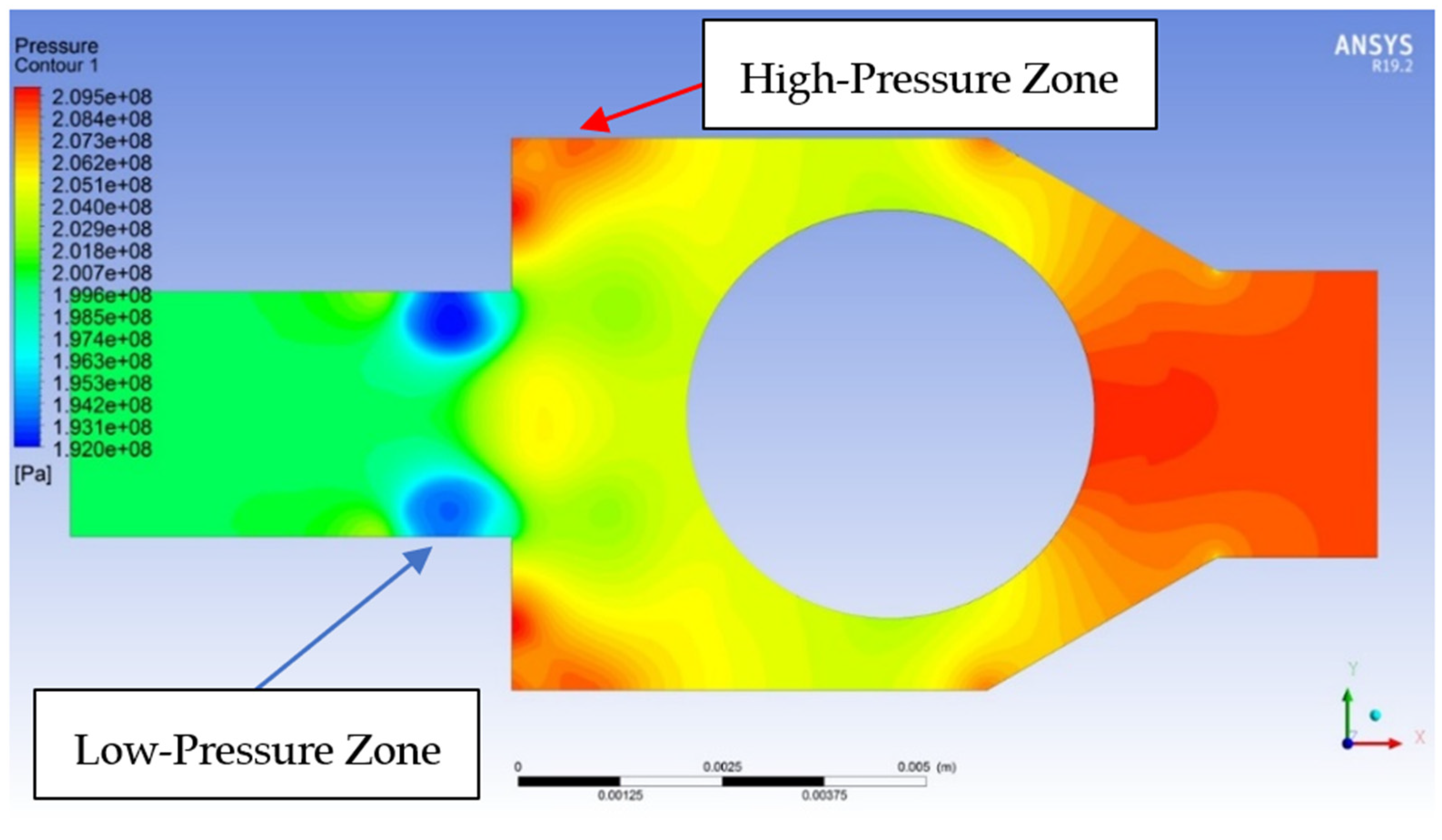
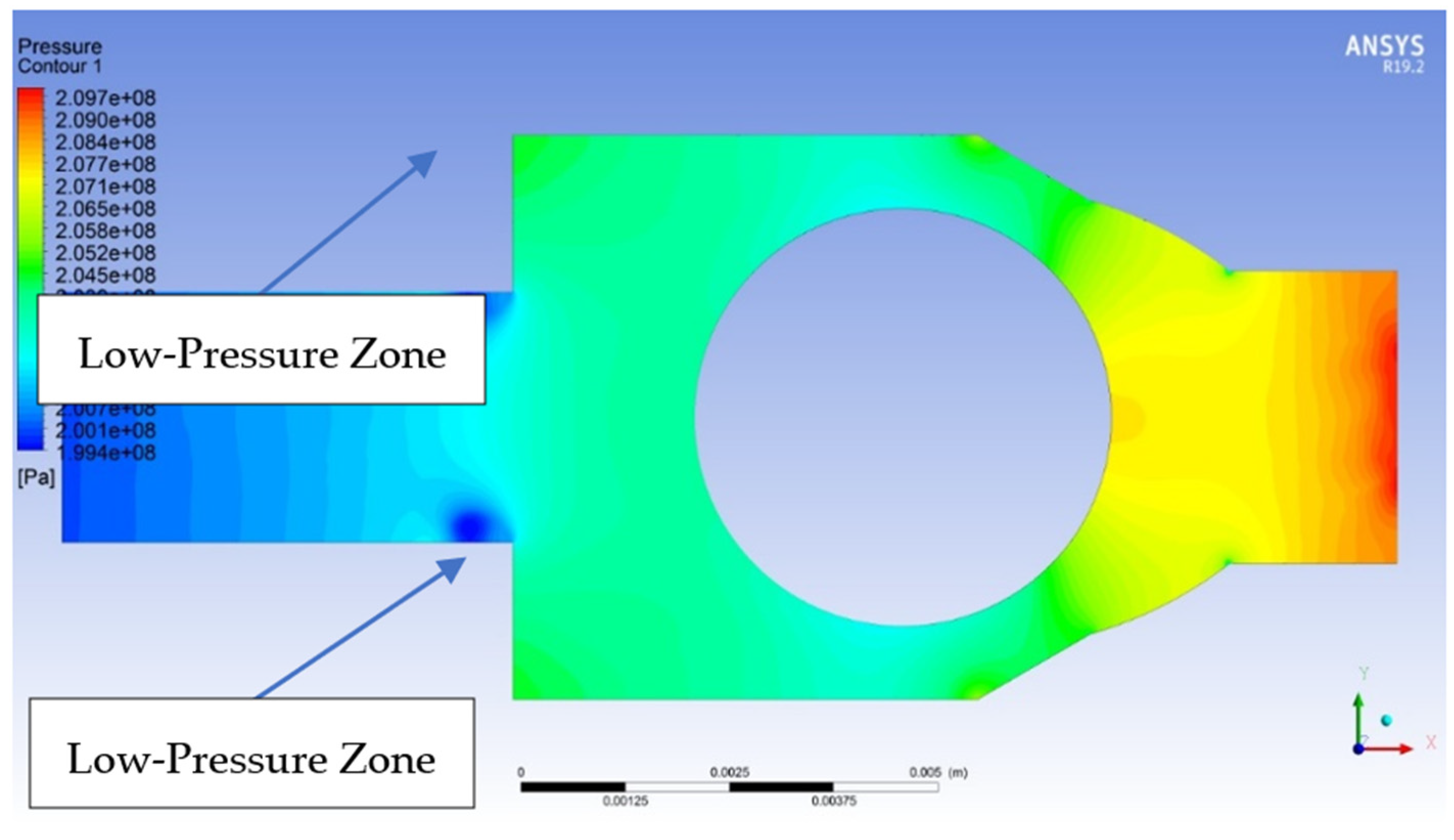
4.1. Pressure CFD Analysis
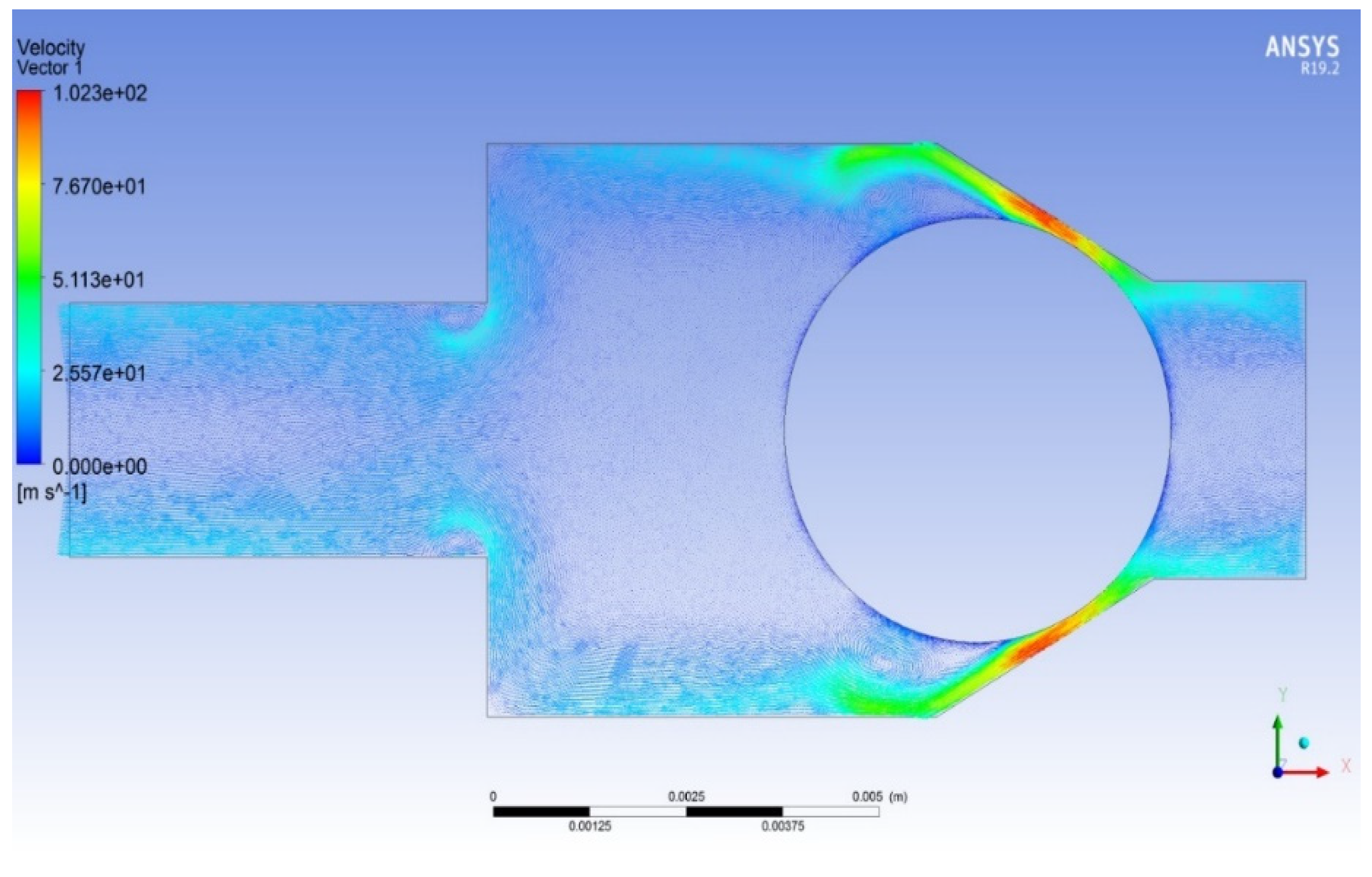
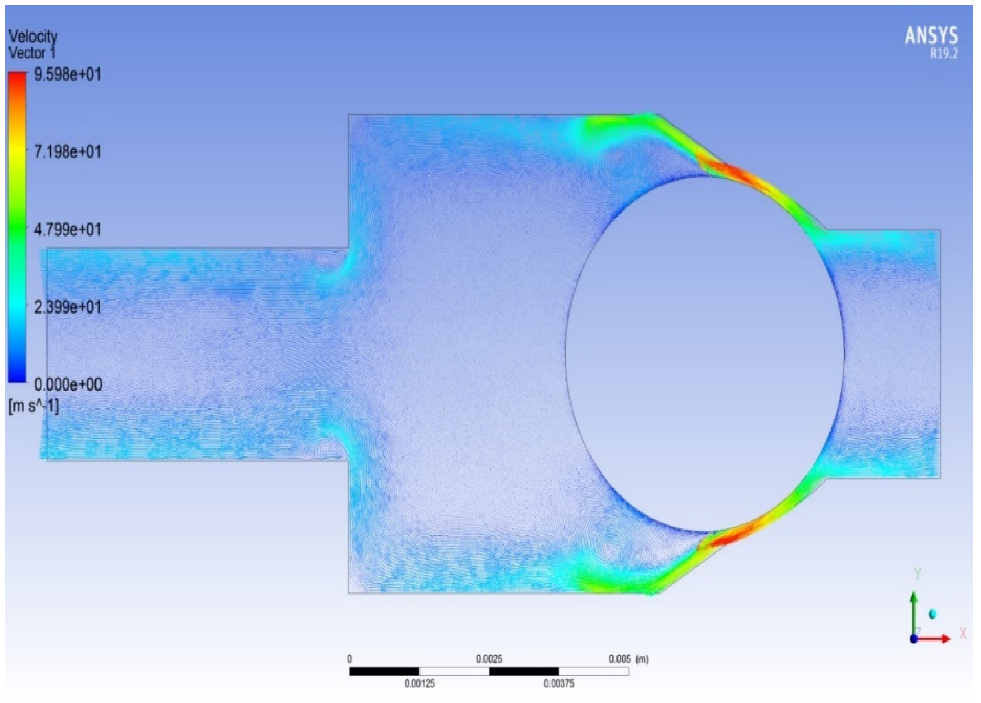
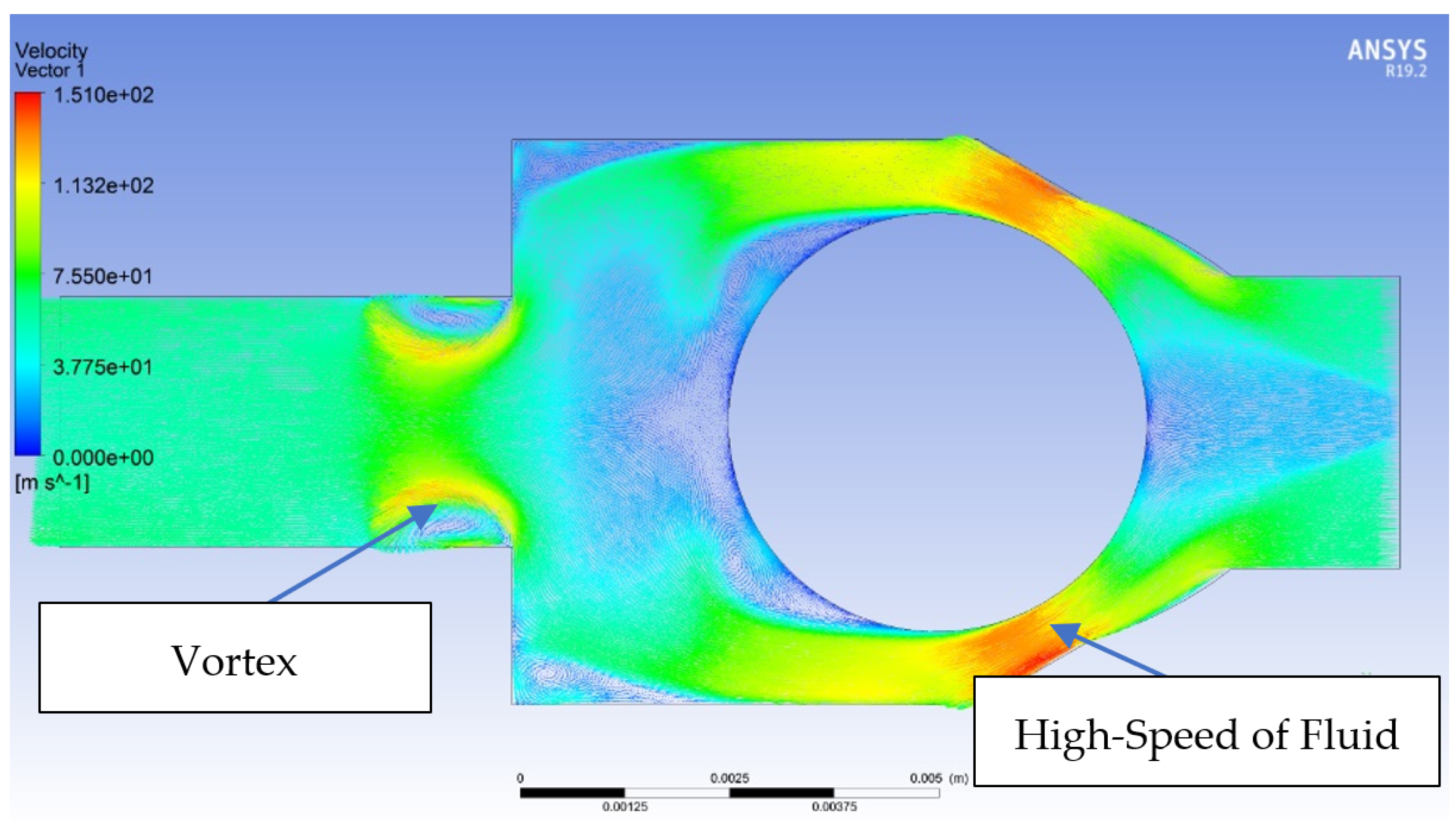
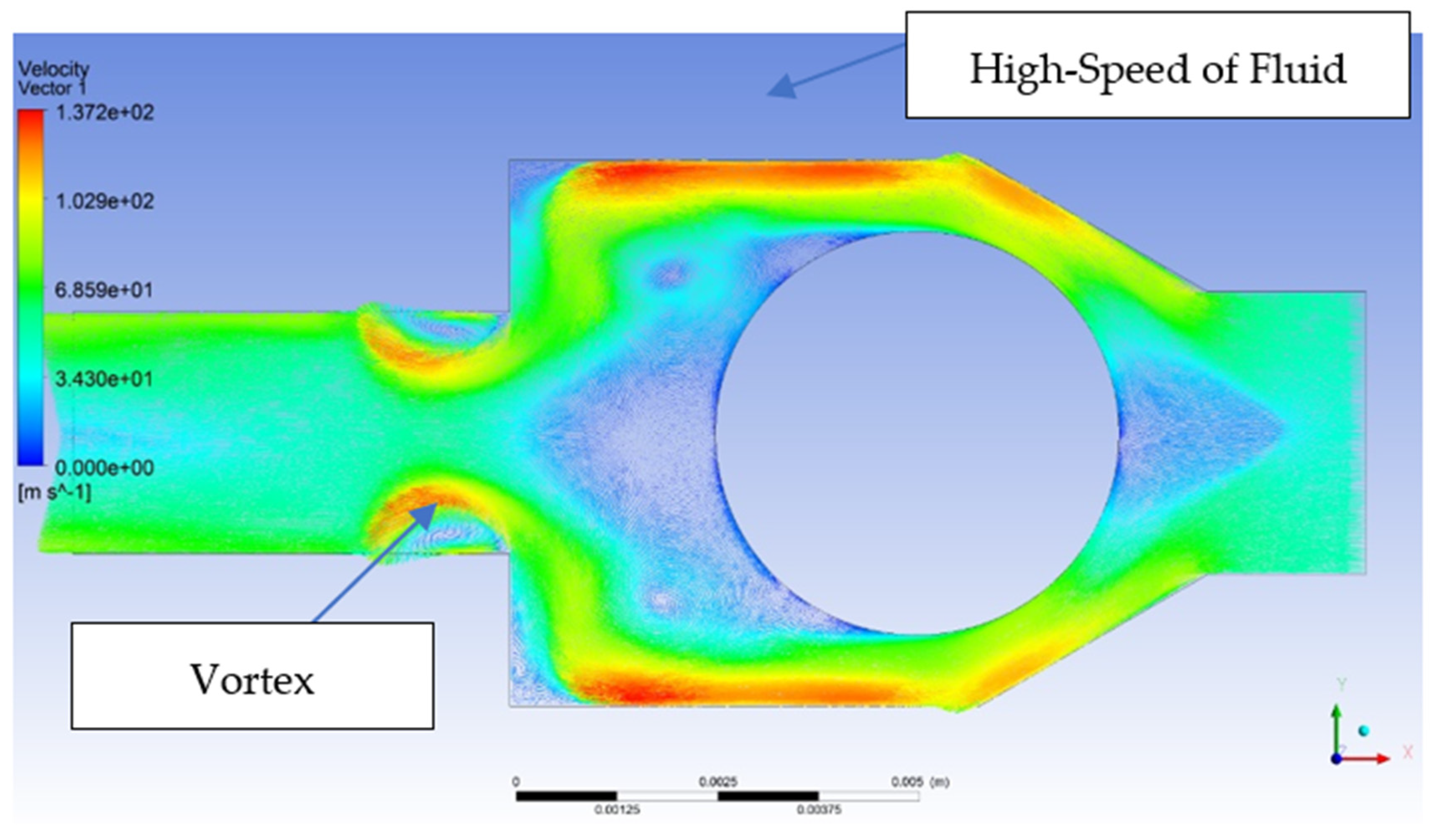
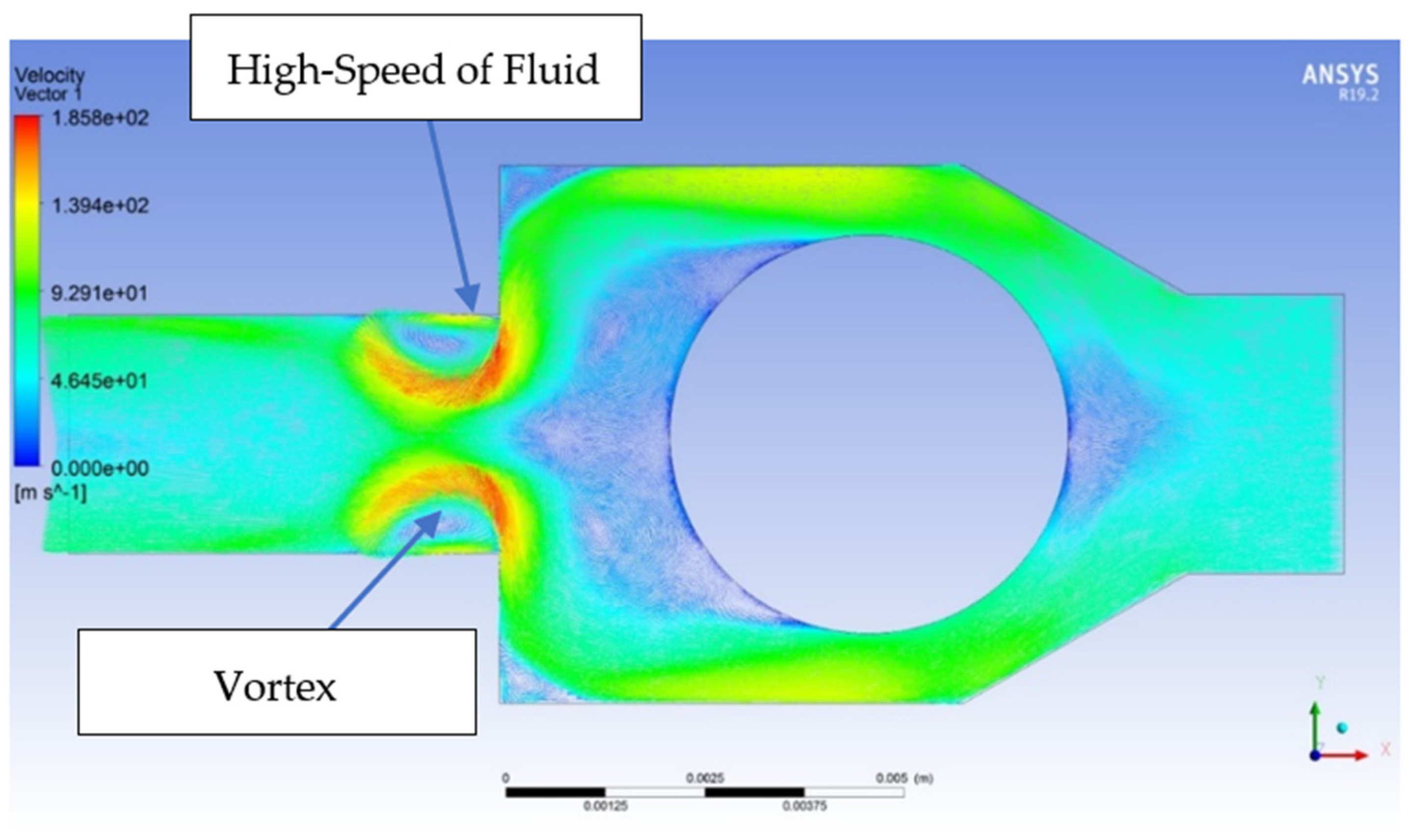
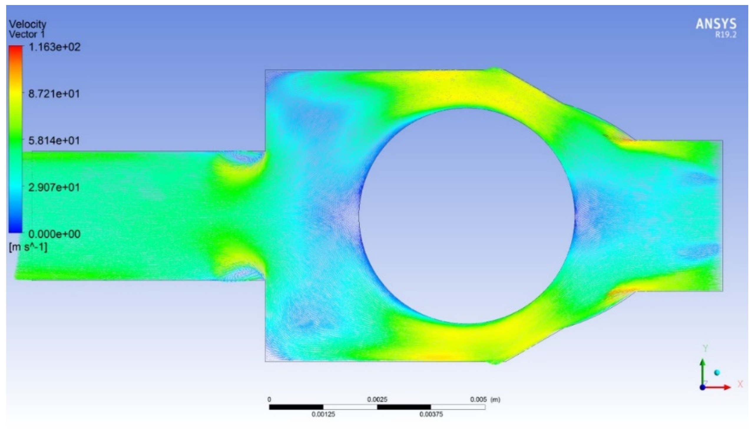
4.2. Velocity CFD Analysis
5. Conclusions
Author Contributions
Funding
Institutional Review Board Statement
Conflicts of Interest
References
- Xu, J.; Hu, H.; Chang, W. Research on Pressure Stability Control of High-pressure Common Rail System Based on Differential Equation Optimization Model. J. Phys. Conf. Ser. 2020, 1549, 052081. [Google Scholar] [CrossRef]
- Osipowicz, T.; Bramek, K.F.; Stoeck, T. Testing of modern common rail fuel injectors. Combust. Engines 2015, 162, 688–694. [Google Scholar]
- Petrea, N.D.; Bujoreanu, C. Importance of fuel injection system for low emissions, combustion noise and low fuel consumption. IOP Conf. Ser. Mater. Sci. Eng. 2018, 444, 042012. [Google Scholar] [CrossRef]
- Ling, M.; He, X.; Wu, M.; Cao, L. Dynamic Design of a Novel High-Speed Piezoelectric Flow Control Valve Based on Compliant Mechanism. IEEE/ASME Trans. Mechatron. 2022, 1–9. [Google Scholar] [CrossRef]
- Tamburrano, P.; Amirante, R.; Distaso, E.; Plummer, A.R. Full simulation of a piezoelectric double nozzle flapper pilot valve coupled with a main stage spool valve. Energy Procedia 2018, 148, 487–494. [Google Scholar] [CrossRef]
- Hardy, C.S.; Hudson, C.M.; Harper, M.S.; Ainsworth, D.M. Pressure is nothing without control: Evolution of control valve design. In Fuel Systems for IC Engines; Woodhead Publishing: Sawston, UK, 2012; pp. 115–128. [Google Scholar]
- Gupta, V.K.; Zhang, Z.; Sun, Z. Modeling and control of a novel pressure regulation mechanism for common rail fuel injection systems. Appl. Math. Model. 2011, 35, 3473–3483. [Google Scholar] [CrossRef]
- Pendzialek, M.; Schneider, J.; Höhe, K.; Zentner, L. Miniaturization of Check Valves. Mech. Mach. Sci. 2016, 45, 15–26. [Google Scholar]
- Yidong, X.; Xiaodong, L.; Hong, L. A Finite Volume Method Based on a WENO Reconstruction for Compressible Flows on Hybrid Grids. In Proceedings of the 52nd Aerospace Sciences Meeting, National Harbor, MD, USA, 13–17 January 2014. [Google Scholar]
- Santamaria, A.; Aleker, J. Spring Retaining Sleeve. U.S. Patent US20110089359A1, 21 April 2011. [Google Scholar]
- Santamaria, A. Exhaust Valve i.e., Return Valve, for Common-Rail-High Pressure Pump Utilized in Common-Rail-Fuel Injection System, Has Valve Element Comprising Casing and Ball That Is Connected with Casing in Fixed Manner and Guided Indirectly over Casing. Germany Patent DE102010061783A1, 24 May 2012. [Google Scholar]
- Masaya, M.; Makoto, T.; Nobuyuki, O. Negative Magnus lift on a rotating sphere at around the critical Reynolds number. Phys. Fluids 2012, 24, 014102. [Google Scholar]
- Elldakli, F.; Soliman, M. Optimum design for new gas lift valve seat. J. Pet. Sci. Eng. 2017, 149, 456–464. [Google Scholar] [CrossRef]
- Lisowski, E.; Filo, G. CFD analysis of the characteristics of a proportional flow control valve with an innovative opening shape. Energy Convers. Manag. 2016, 123, 15–28. [Google Scholar] [CrossRef]
- Hart, J. Comparison of turbulence modeling approaches to the simulation of a dimpled sphere. Procedia Eng. 2016, 147, 68–73. [Google Scholar] [CrossRef]
- Bandari, S.R. Investigation on Flow Control Valve by CFD Simulation. Master’s Thesis, Blekinge Institute of Technology, Karlskrona, Sweden, 2017. [Google Scholar]
- Perdikaris, P.G.; Kaiktsis, L.; Triantafyllou, G.S. Computational study of flow structure and forces on a cylinder vibrating transversely and in-line to a steady flow: Effects of sub-harmonic excitation. In Proceedings of the Pressure Vessels and Piping Conference, Prague, Czech Republic, 26–30 July 2009; pp. 475–479. [Google Scholar]
- Zuhal, L.R.; Dung, D.V.; Sepnov, A.J.; Muhammad, H. Core Spreading Vortex Method for Simulating 3D Flow around Bluff Bodies. J. Eng. Technol. Sci. 2014, 46, 436–454. [Google Scholar] [CrossRef][Green Version]
- Tofa, M.M.; Maimun, A.; Ahmed, Y.M.; Jamei, S.; Abyn, H. Experimental and Numerical Studies of Vortex Induced Vibration on Cylinder. J. Teknol. 2014, 66, 169–175. [Google Scholar]
- Kurtulus, A.B.; Atmaca, M.; Girgin, I.; Ezgi, C. Forces Acting on and Flow Behind a Sphere. In Proceedings of the ASME-Ati-Uit 2015 Conference on Thermal Energy Systems: Production, Storage, Utilization and the Environment, Napoli, Italy, 17–20 May 2015. [Google Scholar]
- Moradian, N.; Ting, D.S.-K.; Cheng, S. The effects of freestream turbulence on the drag coefficient of a sphere. Exp. Therm. Fluid Sci. 2009, 33, 460–471. [Google Scholar] [CrossRef]
- Iordache, R.C.; Petrea, N.D.; Bujoreanu, C. Wear’s issues on high-pressure common rail pumps. IOP Conf. Ser. Mater. Sci. Eng. 2020, 724, 012021. [Google Scholar] [CrossRef]
- Kajiwara, S. Effect of the check ball and inlet position on hydraulic L-shaped check ball behavior. J. Fluids Struct. 2014, 48, 497–506. [Google Scholar] [CrossRef]
- Himr, D.; Habán, V.; Hudec, M. Experimental investigation of check valve behaviour during the pump trip. J. Phys. Conf. Ser. 2017, 813, 012054. [Google Scholar] [CrossRef]
- Ball Check Valves. Available online: https://www.precisionballs.com/ball_valve.php (accessed on 19 February 2022).
- Petrea, N.D.; Bujoreanu, C.; Rîpanu, I.E. Influence of ball-seat contact on the noise emissions from common-rail pump outlet valve opening. IOP Conf. Ser. Mater. Sci. Eng. 2018, 444, 042012. [Google Scholar] [CrossRef]
- Petrea, N.D.; Bujoreanu, C.; Alaci, S. Analysis of the noise emissions of a common-rail pump before and after an endurance test. IOP Conf. Ser. Mater. Sci. Eng. 2019, 591, 012064. [Google Scholar] [CrossRef]
- Pourhoseini, S.H.; Nikzad, R. An experimental study on the effect of inlet diesel fuel temperature on mass flow choking, flame penetration, temperature, radiative characteristics and NOx pollutant emission of an oil burner. J. Braz. Soc. Mech. Sci. Eng. 2019, 41, 492. [Google Scholar] [CrossRef]
- Payr, R.; Salvador, F.J.; Gimeno, J.; Bracho, G. The effect of temperature and pressure on thermodynamic properties of diesel. Fuel 2011, 90, 1172–1180. [Google Scholar] [CrossRef]
- Viel, A. Strong Coupling of Modelica System-Level Models with Detailed CFD Models for Transient Simulation of Hydraulic Components in their Surrounding Environment. In Proceedings of the 8th International Modelica Conference, Dresden, Germany, 20–22 March 2011; pp. 256–265. [Google Scholar]
- Mittwollen, N.; Michl, T.; Breit, R. Parametric hydraulic valve model including transitional flow effects. Math. Model. 1997, 11, 599–604. [Google Scholar]
- Iordache, R.C.; Bujoreanu, C.; Petrea, N.D.; Ianus, G. Simulation of high-pressure pump behaviour after running in urban regime. IOP Conf. Ser. Mater. Sci. Eng. 2020, 997, 012014. [Google Scholar] [CrossRef]
- Wei, M.; Cheng, L.; Hongyu, W.; Zhi, Z.; Jianfeng, Z.; Hong, J. Discharge coefficient of pilot poppet valve at low Reynolds number. Flow Meas. Instrum. 2022, 85, 102141. [Google Scholar]
- Hutagalung, S.S. Effect of Release Coefficient of Orifice Plate on Water Fluid Flow Systems. J. Phys. Conf. Ser. 2019, 1230, 012086. [Google Scholar] [CrossRef]
- Doddannavar, R.; Barnard, A. Practical Hydraulic Systems: Operation and Troubleshooting for Engineers and Technicians, 1st ed.; Elsevier: Amsterdam, The Netherlands, 2005. [Google Scholar]
- Parr, A. Hydraulics and Pneumatics—A Technician’s and Engineer’s Guide, 3rd ed.; Elsevier: Edinburgh, UK, 2011. [Google Scholar]
- Al Omari, B. On the Relation between Radius and Coefficient of Drag; Waterloo University: Waterloo, ON, Canada, 2020. [Google Scholar]
- Dobeš, J.; Kozubková, M. The Influence of Numerical Models on Determining the Drag Coefficient. EPJ Web Conf. 2014, 67, 02019. [Google Scholar] [CrossRef]
- Polezhaev, Y.V.; Chircov, I.V. Drag Coefficient. 2 February 2011. Available online: https://www.thermopedia.com/content/707/ (accessed on 22 August 2022).
- Jorach, R.; Judge, R.; Annycke, B.; Lamacchia, F. Diesel common rail fuel systems technology for high efficiency ultra low emissions medium duty engines. In Fuel Systems for IC Engines; Woodhead Publishing: Sawston, UK, 2012; pp. 141–154. [Google Scholar]
- Chen, G.; Chen, C.; Yuan, Y.; Zhu, L. Modelling and Simulation Analysis of High-Pressure Common Rail and Electronic Controlled Injection System for Diesel Engine. Appl. Math. Nonlinear Sci. 2020, 5, 345–356. [Google Scholar] [CrossRef]
- Pantokratoras, A. Flow past a rotating sphere in a non-Newtonian, power-law fluid, up to a Reynolds number of 10,000. Chem. Eng. Sci. 2018, 181, 311–314. [Google Scholar] [CrossRef]
- Liu, D.N.; Yan, Z.J.; Yan, X.L.; Zhu, X.H.; Cheng, D.; Fang, X. Experimental and simulation studies on critical cavitation pressure of oily medium. IOP Conf. Ser. Mater. Sci. Eng. 2019, 504, 012103. [Google Scholar] [CrossRef]
- Haixuan, Y.; Xiao-Lei, X. Fatigue failure of high-pressure oil-pipes of truck diesel engine. Eng. Fail. Anal. 2019, 97, 145–160. [Google Scholar]
- Grinis, L.; Haslavsky, V. Turbulence Modeling Applied to Flow over a Hydraulic Ball Check Valve. Engineering 2013, 5, 685–691. [Google Scholar] [CrossRef][Green Version]


| Common-Rail Pump Speed [rpm] | High-Pressure Accumulator Pressure (pdn) [bar] | Compression Chamber Pressure (pup) [bar] |
|---|---|---|
| 100 | 100 | 120 |
| 800 | 300 | 330 |
| 2000 | 1600 | 1680 |
| 4000 | 2000 | 2100 |
| 5000 | 2000 | 2100 |
| Fluid Temperature (°C) | Kinematic Viscosity (ν) [cSt] | Dynamic Viscosity (μ) [mPa·s] | Density (ρ) [g/cm3] |
|---|---|---|---|
| 50 | 1.96 | 1.45 | 0.82 |
| Maximum Fluid Passage Area [mm2] | Ball Diameter Db [mm] | Maximum Valve Opening Height [mm] |
|---|---|---|
| 9.621 | 5 | 1.256 |
| Common-Rail Pump Speed [rpm] | High-Pressure Accumulator Pressure | Valve Opening Height (x) [mm] |
|---|---|---|
| 100 | 100 | 0.025 |
| 800 | 300 | 0.201 |
| 2000 | 1600 | 0.503 |
| 4000 | 2000 | 1.005 |
| 5000 | 2000 | 1.257 |
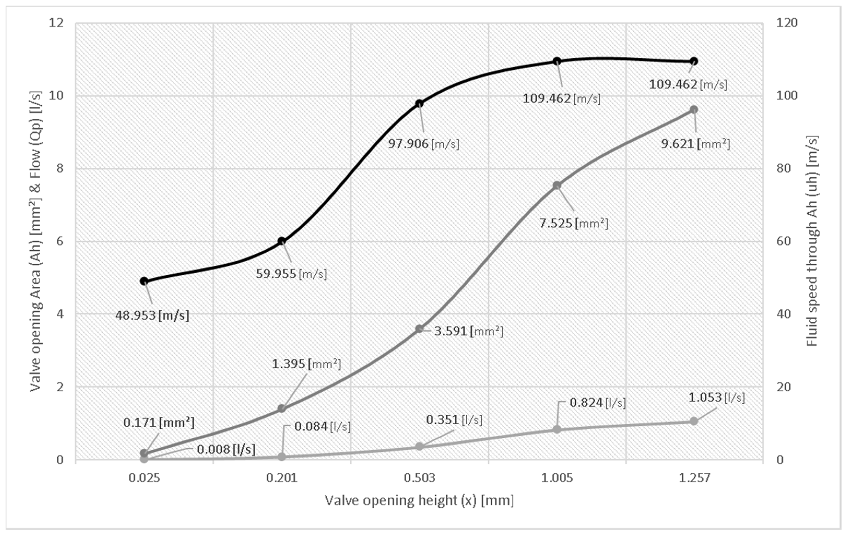
| Valve Opening Height (x) [mm] | Valve Opening Area (Ah) [mm2] | Flow (Qp) [l/s] | Fluid Speed through Ah (uh) [m/s] |
|---|---|---|---|
| 0.025 | 0.171 | 0.008 | 48.953 |
| 0.201 | 1.395 | 0.084 | 59.955 |
| 0.503 | 3.591 | 0.351 | 97.906 |
| 1.005 | 7.525 | 0.824 | 109.462 |
| 1.257 | 9.621 | 1.053 | 109.462 |
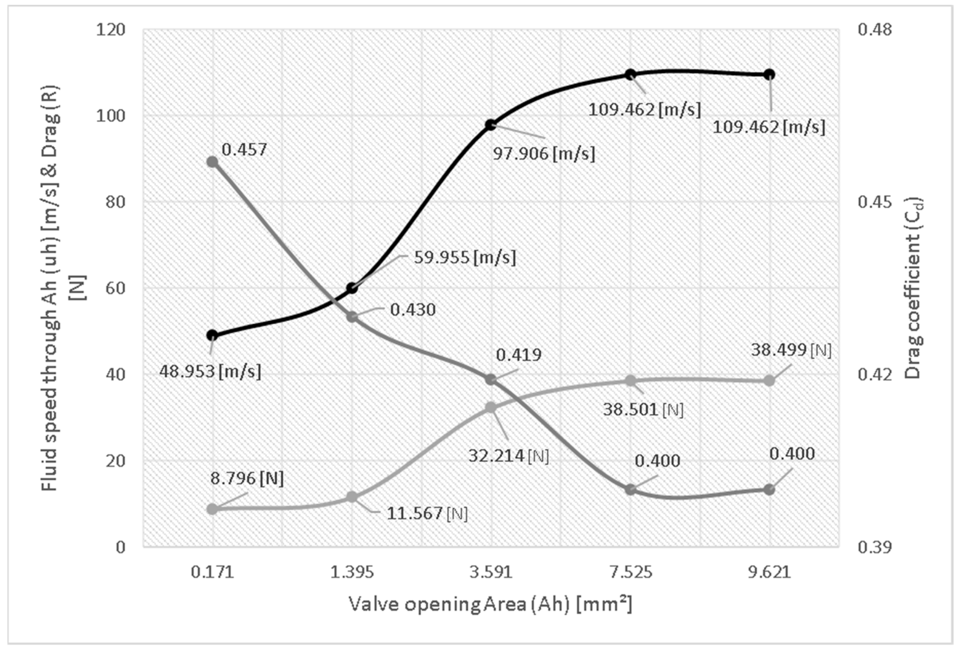
| Ball Diameter (Db) [mm] | Valve Opening Area (Ah) [mm2] | Fluid Speed Through Ah (uh) [m/s] | Drag Coefficient (Cd) | Drag (R) [N] | Reynolds Number (Re) |
|---|---|---|---|---|---|
| 5 | 0.171 | 48.953 | 0.457 | 8.796 | 11,650 |
| 1.395 | 59.955 | 0.430 | 11.567 | 40,770 | |
| 3.591 | 97.906 | 0.419 | 32.214 | 106,800 | |
| 7.525 | 109.462 | 0.400 | 38.501 | 172,900 | |
| 9.621 | 109.462 | 0.400 | 38.499 | 195,500 |
Publisher’s Note: MDPI stays neutral with regard to jurisdictional claims in published maps and institutional affiliations. |
© 2022 by the authors. Licensee MDPI, Basel, Switzerland. This article is an open access article distributed under the terms and conditions of the Creative Commons Attribution (CC BY) license (https://creativecommons.org/licenses/by/4.0/).
Share and Cite
Petrea, N.-D.; Iordache, R.-C.; Bujoreanu, C. Analysis of Ball Check Valves with Conical and Spherical Seat Designs from Common-Rail Pumps. Machines 2022, 10, 959. https://doi.org/10.3390/machines10100959
Petrea N-D, Iordache R-C, Bujoreanu C. Analysis of Ball Check Valves with Conical and Spherical Seat Designs from Common-Rail Pumps. Machines. 2022; 10(10):959. https://doi.org/10.3390/machines10100959
Chicago/Turabian StylePetrea, Narcis-Daniel, Razvan-Constantin Iordache, and Carmen Bujoreanu. 2022. "Analysis of Ball Check Valves with Conical and Spherical Seat Designs from Common-Rail Pumps" Machines 10, no. 10: 959. https://doi.org/10.3390/machines10100959
APA StylePetrea, N.-D., Iordache, R.-C., & Bujoreanu, C. (2022). Analysis of Ball Check Valves with Conical and Spherical Seat Designs from Common-Rail Pumps. Machines, 10(10), 959. https://doi.org/10.3390/machines10100959