
Ultimate Bearing Capacity of Bottom Sealing Concrete in Underwater Deep Foundation Pit: Theoretical Calculation and Numerical Analysis


 , and
, and 
Abstract
:1. Introduction
2. Theoretical Calculation
2.1. Ultimate Bending Moment and Ultimate Stress
2.1.1. Approximate Solution Derived by Elasticity Method
2.1.2. Traditional Method
2.2. Ultimate Bonding Strength
3. Numerical Simulation and Theoretical Verification Calculation
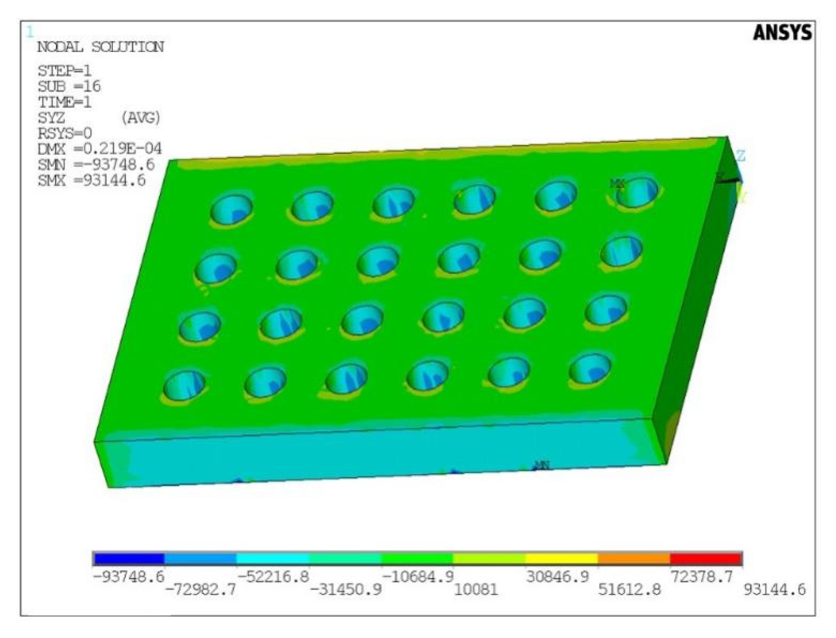
3.1. Numerical Simulation Based on ANSYS
3.2. Theoretical Verification Calculation
3.2.1. Maximum Tensile Stress Verification Calculation
3.2.2. Bonding Strength Verification Calculation
4. Discussion
- It can be seen that the tensile stress of the bottom sealing concrete calculated by the approximate solution is closer to the monitored value than the traditional method. Therefore, the approximate solution is more accurate than the traditional method.
- The result calculated by traditional method is safer in engineering. But, if the traditional method is adopted, the amount of concrete required during construction will be much larger, which will cause waste of materials.
- The numerical simulation method is closer to the monitored value than the above two theoretical calculation methods, but the steps are relatively cumbersome and require more time.
- When the accuracy required in the project is not high, the traditional method can be used; when the required accuracy is moderate, the approximate solution can be used; when the required accuracy is high, the numerical simulation method can be used.
- In the future research, for the elastic mechanics method, the influence of the holes in the bottom-sealed concrete can be considered to improve the accuracy of the calculation; for the numerical simulation method, the operation steps can be simplified.
5. Conclusions
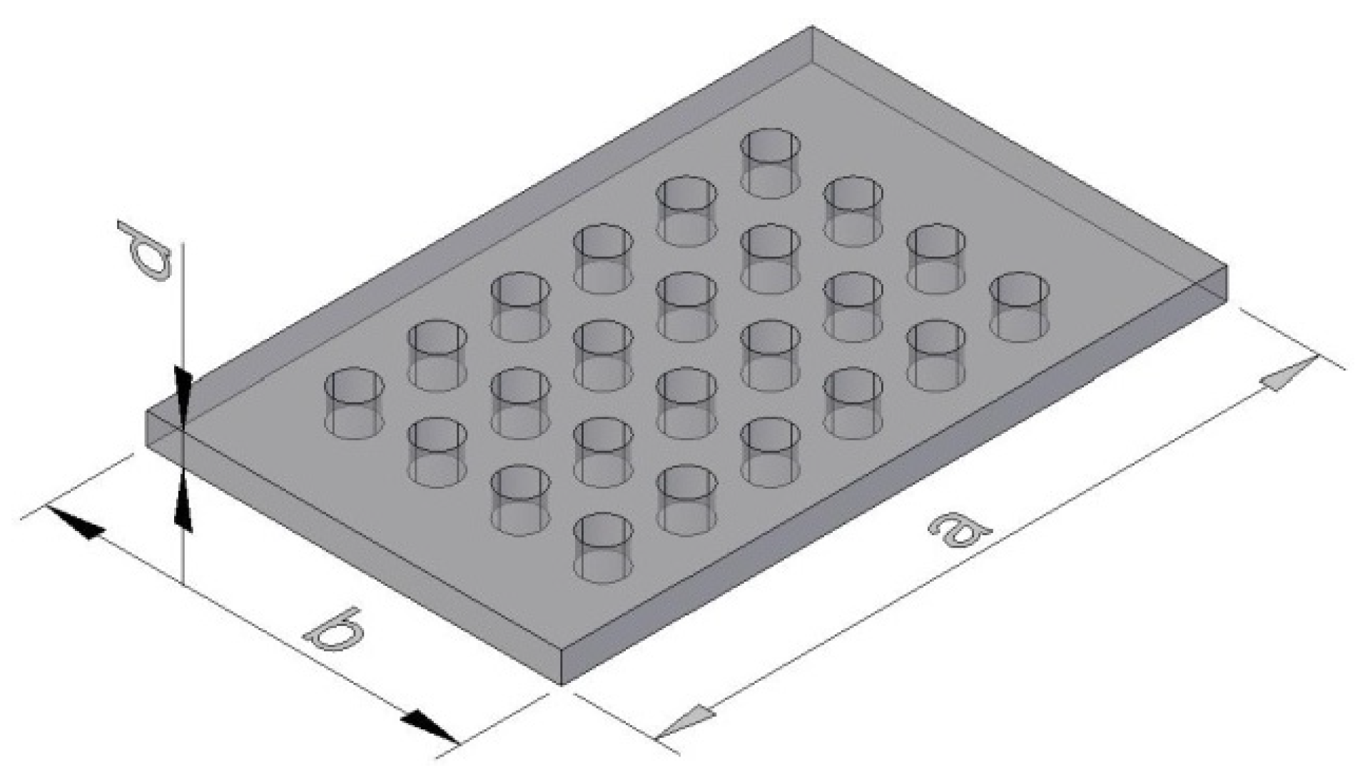
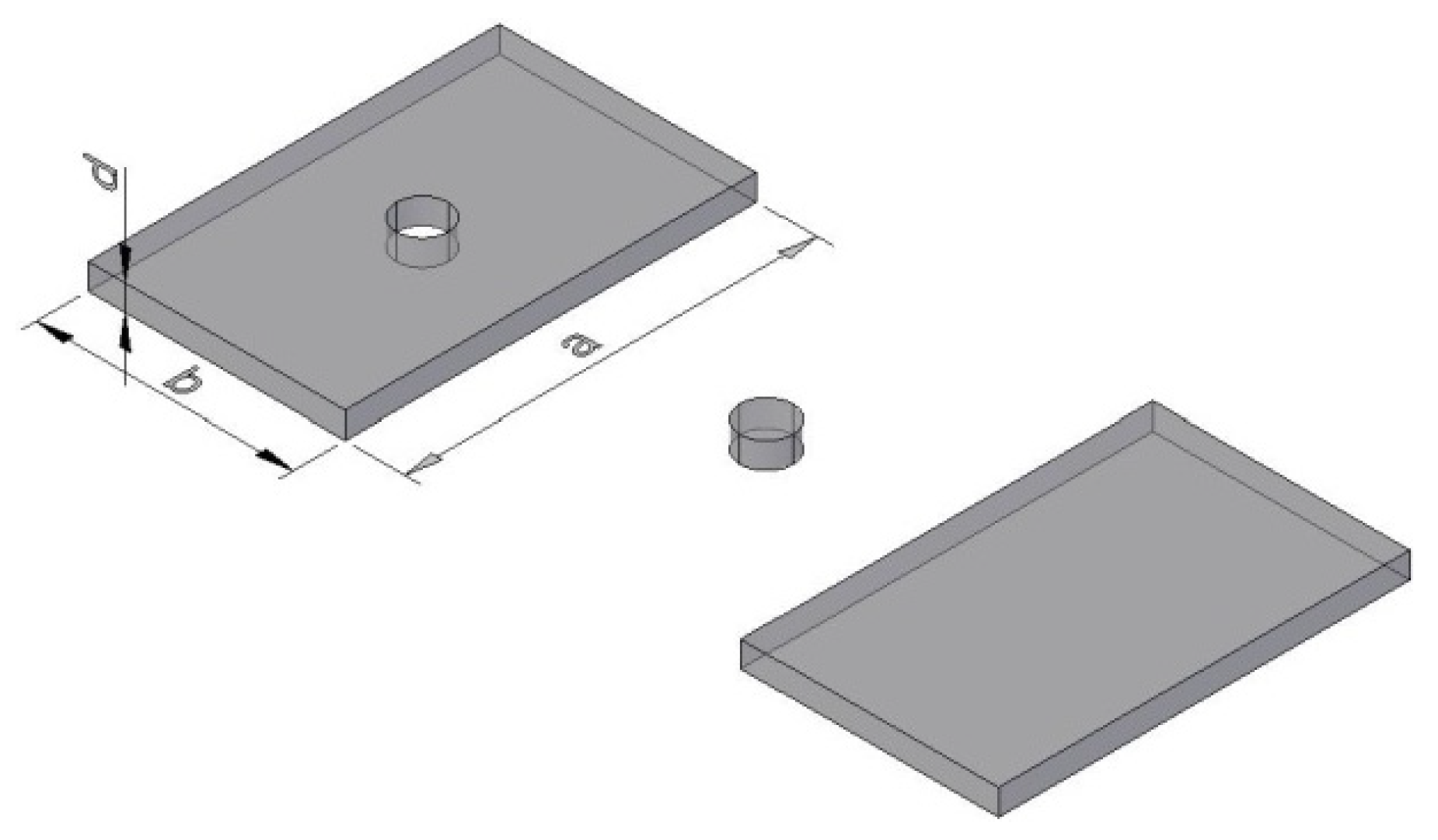
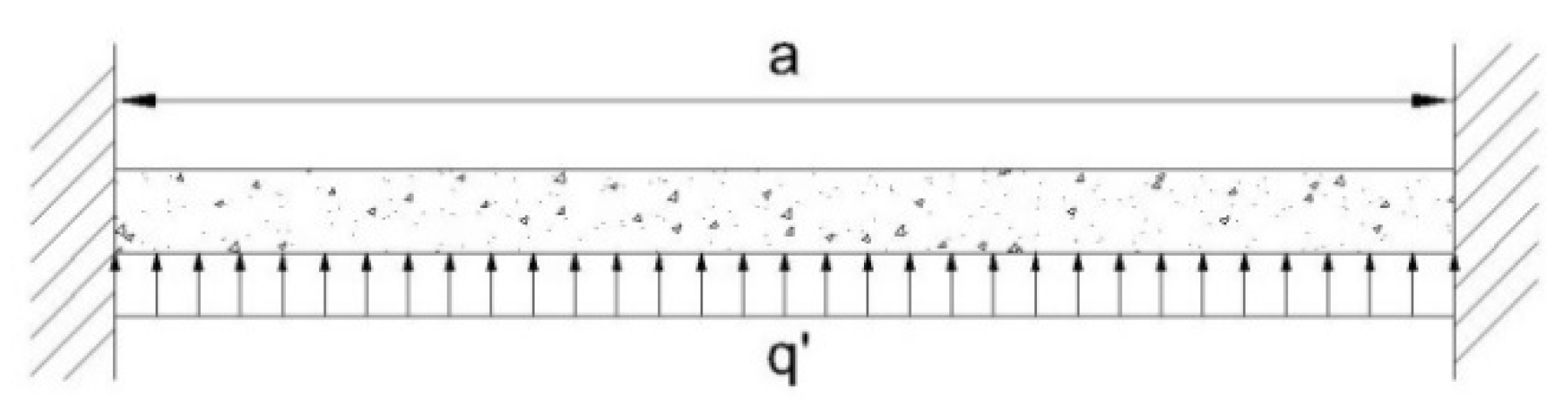
- When calculating the maximum compressive stress and tensile stress of the bottom sealing concrete, the concrete can be regarded as an isotropic, continuous, uniform, and small deformation elastic material, and the bottom sealing concrete can be simplified into an elastic thin slab, and the elasticity method is used for the calculation. The traditional method can also be used to divide the bottom sealing concrete slab along the long side and divide it into several concrete beams. The maximum stress obtained by the approximate solution is closer to the actual monitoring value than the traditional method.
- Equation (18) can be used to calculate the ultimate bonding force between the bottom sealing concrete and the steel sleeves. The calculated bonding force is only an average value, and it will be slightly smaller, which can be used to make a rough estimate.
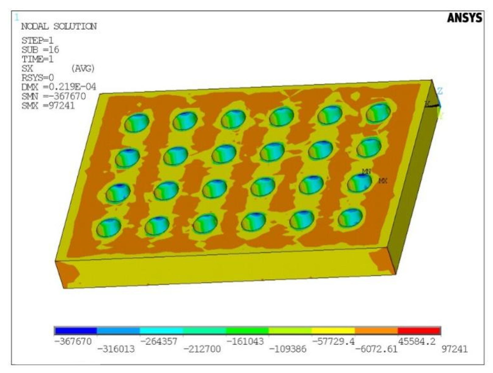
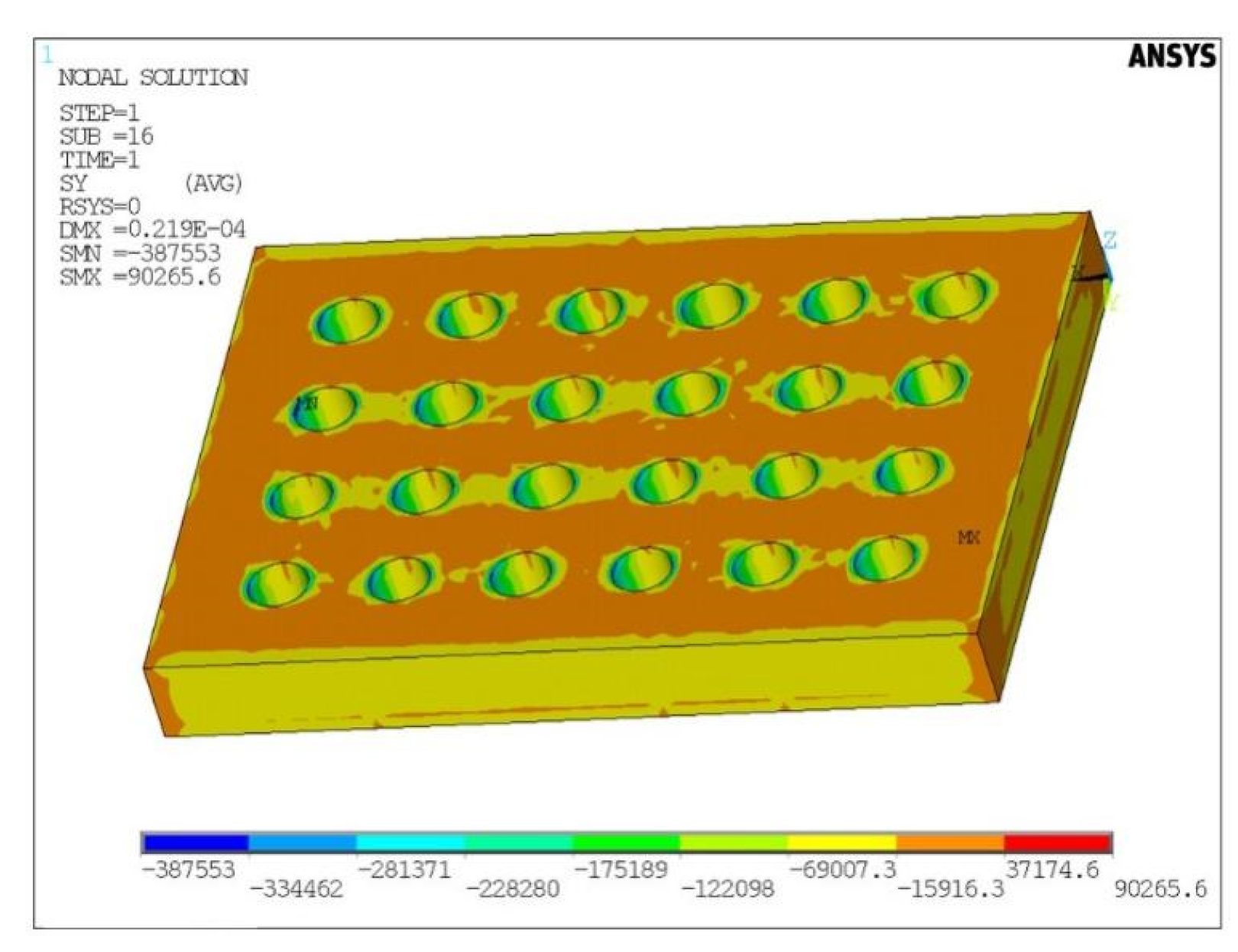
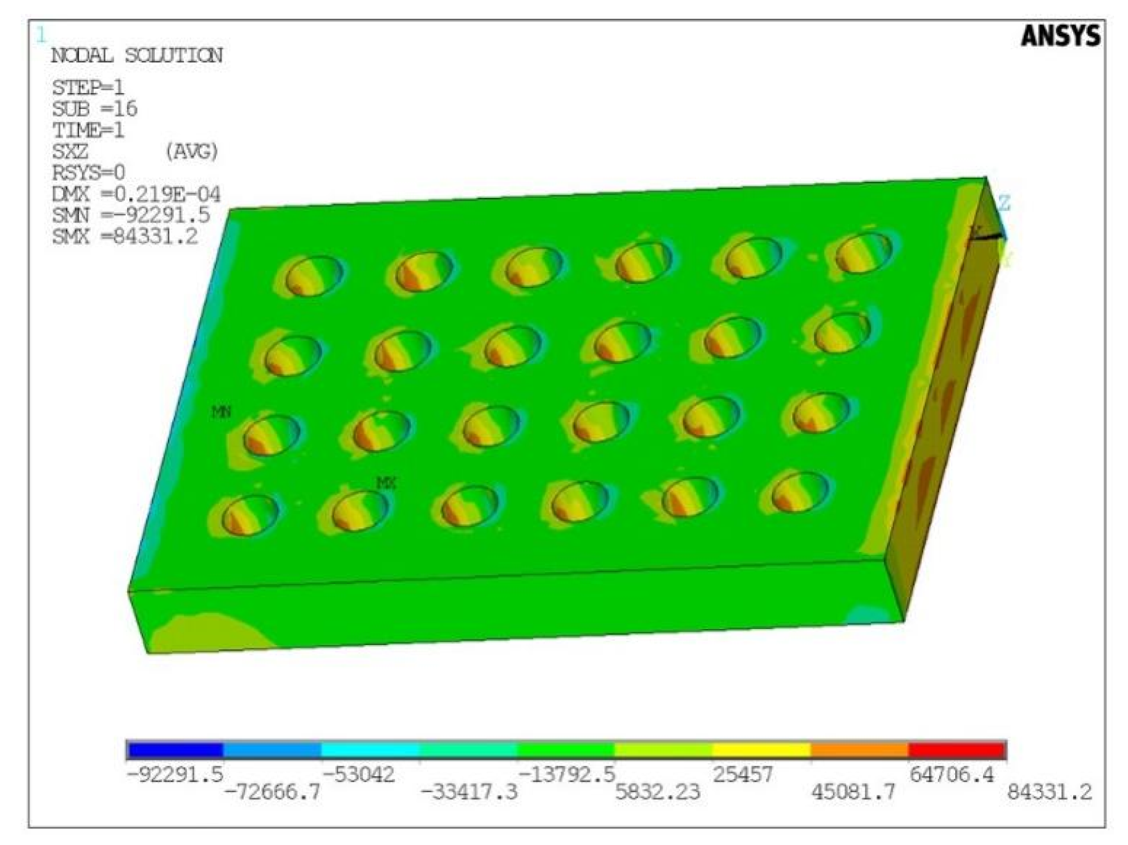
- For the calculation of the maximum compressive stress, tensile stress, and cohesive force of the bottom sealing concrete, it can be assumed that the bottom sealing concrete material is isotropic, homogeneous, and dense, and the ANSYS finite element software can be used for numerical simulation.
Author Contributions
Funding
Institutional Review Board Statement
Informed Consent Statement
Data Availability Statement
Conflicts of Interest
References
- Li, S.; Yao, A.; Ma, Y. Failure Mechanism and Passive Earth Pressure on Foundation Pits with Skirt Reinforcement. Soil Mech. Found. Eng. 2021, 58, 25–33. [Google Scholar] [CrossRef]
- Wang, Z.; Zhang, N.; Li, Q.; Chen, X. Influence of Sand-Rubber Mixtures Backfill on Mechanical Properties of Bridge Abutment and Foundation Piles. Soil Mech. Found. Eng. 2018, 55, 55–61. [Google Scholar] [CrossRef]
- Benmebarek, N.; Bensmaine, A.; Benmebarek, S.; Belounar, L. Critical Hydraulic Head Loss Inducing Failure of a Cofferdam Embedded in Horizontal Sandy Ground. Soil Mech. Found. Eng. 2014, 51, 173–180. [Google Scholar] [CrossRef]
- Blum, H. Einspannung Sverhaeltnisse bei Bohlwerken; Wilhelm Ernst & Sohn: Berlin, Germany, 1931. [Google Scholar]
- Lohmeyer, E. Discussion to ‘Analysis of sheet pile bulkheads’ by P.Baumann. Proc. Am. Soc. Giv. Eng. 1934, 61, 347–355. [Google Scholar]
- Terzaghi, K. Stability and stiffness of cellular cofferdams. Am. Soc. Civ. Eng. Trans. 1945, 110, 1083–1119. [Google Scholar] [CrossRef]
- Ovesen, N.K. Cellular Cofferdams. Ph.D. Thesis, Danish Geotechnical Institute, Copenhagen, Denmark, 1962. [Google Scholar]
- Banerjee, S.M. Design charts for double-walled cofferdam. J. Geotech. Eng. 1993, 119, 214–222. [Google Scholar] [CrossRef]
- Clasmeier, H.D. A Comparison between Circular Cell Cofferdam and Double Wall Cofferdam. In Proceedings of the 11th International Harbour Congress, Antwerpen, Belgium, 17–21 June 1996. [Google Scholar]
- Lefas, I.D.; Georgiannou, V.N. Analysis of a cofferdam support and design implications. Comput. Struct. 2001, 79, 2461–2469. [Google Scholar] [CrossRef]
- Hu, Q. Study on the Application and Development of Double Wall Steel Cofferdam Technology for Bridge Foundation Construction. Master’s Thesis, Southwest Jiaotong University, Chengdu, China, 2005. (In Chinese). [Google Scholar]
- Pan, H.; Wang, J.; Cao, H.; Luo, G. Research on Deformation and Internal Force Characteristics of Steel Sheet Pile Cofferdam under Different Construction Procedures. Chin. J. Rock Mech. Eng. 2013, 32, 2316–2324. (In Chinese) [Google Scholar]
- Li, Y. Experiment of Sealing Properties and Structure Design for Steel Sheet Pile Cofferdam. Master’s Thesis, Central South University, Changsha, China, 2013. (In Chinese). [Google Scholar]
- Wen, T. Model Test Study of Bonding Forces between Double-Wall Steel Cofferdam Base Sealing Concrete and Steel Pipe Pile. Master’s Thesis, Chongqing Jiaotong University, Chongqing, China, 2017. (In Chinese). [Google Scholar]
- Chen, W. Study on the Anti-Floating Characteristics of the Concrete Bottom Sealing Structure of Deep Foundation Pit. Master’s Thesis, China University of Geosciences, Beijing, China, 2020. (In Chinese). [Google Scholar]
- He, D. Study on the Construction Technology of the Steel Cofferdam in Complicated Hydro-Geological Conditions. Master’s Thesis, Chongqing Jiaotong University, Chongqing, China, 2016. (In Chinese). [Google Scholar]
- Hua, H. Mechanical Behavior Analysis and Stress Monitoring of Double Wall Steel Cofferdam. Master’s Thesis, Chongqing Jiaotong University, Chongqing, China, 2017. (In Chinese). [Google Scholar]
- Yu, J. Mechanical Characteristics Analysis and Key Technology Research of Single Wall Steel Cofferdam in Deep Water Construction. Master’s Thesis, Changsha University of Science & Technology, Changsha, China, 2018. (In Chinese). [Google Scholar]
- Divyah, N.; Thenmozhi, R.; Neelamegam, M. A comparative study on prediction models for strength properties of LWA concrete using artificial neural network. Rev. Constr. 2020, 1523, 103–111. [Google Scholar]
- Alves de Souza, R.; Breña, S.F. Simplified nonlinear analysis of reinforced concrete coupling beams subjected to cyclic loading. Rev. Constr. 2020, 13666, 224–232. [Google Scholar] [CrossRef]
- Shimpi, V.; Sivasubramanian, M.V.; Singh, S.B. Serviceability analysis and increased axle load performance of heritage arch gallery railway bridge. Rev. Constr. 2021, 21471, 178–189. [Google Scholar]
- Guo, P.; Gong, X.; Wang, Y.; Lin, H.; Zhao, Y. Minimum cover depth estimation for underwater shield tunnels. Tunn. Undergr. Space Technol. 2021, 115, 104027. [Google Scholar] [CrossRef]
- Guo, P.; Gong, X.; Wang, Y. Displacement and force analyses of braced structure of deep excavation considering unsymmetrical surcharge effect. Comput. Geotech. 2019, 115, 104027. [Google Scholar] [CrossRef]
- Zhao, Y.; Wang, Y.; Wang, W.; Tang, L.; Liu, Q. Modeling of rheological fracture behavior of rock cracks subjected to hydraulic pressure and far field stresses. Theor. Appl. Fract. Mech. 2019, 101, 59–66. [Google Scholar] [CrossRef]
- Zhao, Y.; Zhang, L.; Liao, J.; Wang, W.; Liu, Q.; Tang, L. Experimental Study of Fracture Toughness and Subcritical Crack Growth of Three Rocks under Different Environments. Int. J. Geomech. 2020, 20, 04020128. [Google Scholar] [CrossRef]
- Zhao, Y.; Zhang, L.; Wang, W.; Liu, Q.; Tang, L.; Cheng, G. Experimental Study on Shear Behavior and a Revised Shear Strength Model for Infilled Rock Joints. Int. J. Geomech. 2020, 2020, 04020141. [Google Scholar] [CrossRef]
- Wang, Y.; Zhang, H.; Lin, H.; Zhao, Y.; Liu, Y. Fracture behaviour of central-flawed rock plate under uniaxial compression. Theor. Appl. Fract. Mech. 2020, 106, 102503. [Google Scholar] [CrossRef]
- Xu, Z. The Problem of Thin Slab Bending with Small Deflection and Its Classical Solution. In Elasticity, 5th ed.; CSPM: Beijing, China, 2016; Volume 2, pp. 20–23. (In Chinese) [Google Scholar]
- Xu, Z. Thin Slab Bending Problem. In A Concise Course in Elasticity, 4th ed.; Higher Education Press: Beijing, China, 2013; pp. 215–217. (In Chinese) [Google Scholar]
- Jin, G. Deep-Water Bridge Pile Foundation Steel Boxed Cofferdam Construction Technology Research. Master’s Thesis, Chang’an University, Xi’an, China, 2011. (In Chinese). [Google Scholar]


| Parameters | Values |
|---|---|
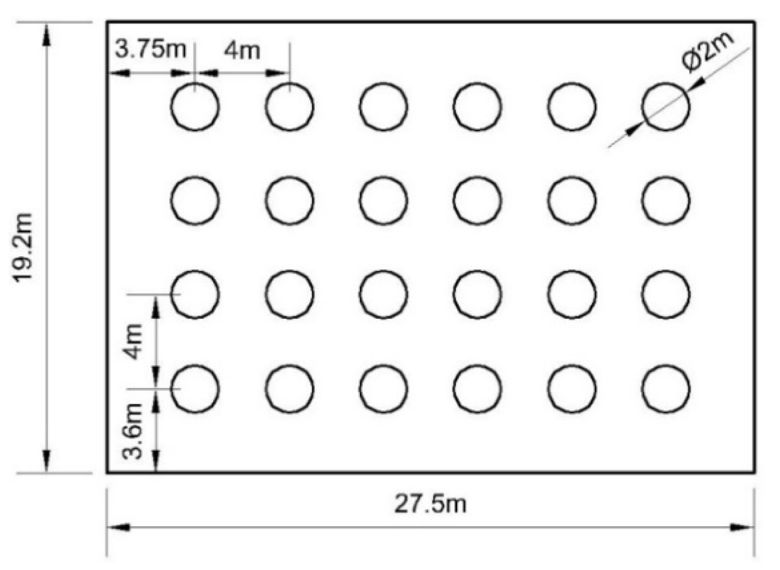
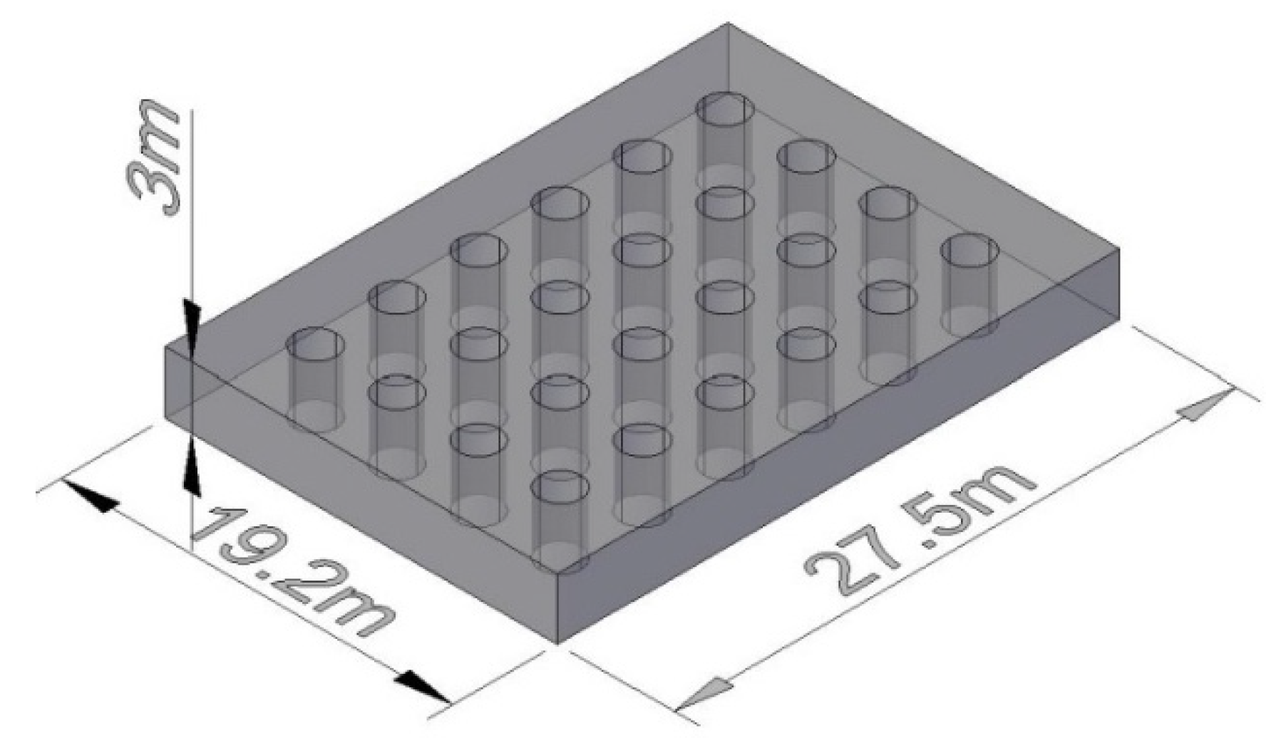
| Piles’ Length | 49.0 m |
| Piles’ Diameter | 2.0 m |
| Piles’ Number | 24 |
| Cofferdam’s Long | 27.5 m |
| Cofferdam’s Wide | 19.2 m |
| Thickness of the Bottom Sealing Concrete | 3.0 m |
| Data Sources | Maximum Tensile Stress/MPa | Relative Error Compared with Monitoring Data |
|---|---|---|
| Approximate Solution | 0.95 | 2.96 |
| Traditional Method | 5.70 | 22.75 |
| Numerical Simulation | 0.39 | 0.625 |
| Monitoring Data | 0.24 | 0 |
| Data Sources | Bonding Force/kPa |
|---|---|
| Equation Calculation | 89.61 |
| Numerical Simulation | 93.75 |
Publisher’s Note: MDPI stays neutral with regard to jurisdictional claims in published maps and institutional affiliations. |
© 2022 by the authors. Licensee MDPI, Basel, Switzerland. This article is an open access article distributed under the terms and conditions of the Creative Commons Attribution (CC BY) license (https://creativecommons.org/licenses/by/4.0/).
Share and Cite
Chen, S.; Li, Y.; Guo, P.; Zuo, X.; Liu, Y.; Yuan, H.; Wang, Y. Ultimate Bearing Capacity of Bottom Sealing Concrete in Underwater Deep Foundation Pit: Theoretical Calculation and Numerical Analysis. Machines 2022, 10, 830. https://doi.org/10.3390/machines10100830
Chen S, Li Y, Guo P, Zuo X, Liu Y, Yuan H, Wang Y. Ultimate Bearing Capacity of Bottom Sealing Concrete in Underwater Deep Foundation Pit: Theoretical Calculation and Numerical Analysis. Machines. 2022; 10(10):830. https://doi.org/10.3390/machines10100830
Chicago/Turabian StyleChen, Shuo, Yonghai Li, Panpan Guo, Xiaohan Zuo, Yan Liu, Haiping Yuan, and Yixian Wang. 2022. "Ultimate Bearing Capacity of Bottom Sealing Concrete in Underwater Deep Foundation Pit: Theoretical Calculation and Numerical Analysis" Machines 10, no. 10: 830. https://doi.org/10.3390/machines10100830
APA StyleChen, S., Li, Y., Guo, P., Zuo, X., Liu, Y., Yuan, H., & Wang, Y. (2022). Ultimate Bearing Capacity of Bottom Sealing Concrete in Underwater Deep Foundation Pit: Theoretical Calculation and Numerical Analysis. Machines, 10(10), 830. https://doi.org/10.3390/machines10100830