Article

Fatigue Analysis of Dozer Push Arms under Tilt Bulldozing Conditions

1
Key Laboratory of High-Efficiency and Clean Mechanical Manufacture, Ministry of Education, School of Mechanical Engineering, Shandong University, Jinan 250061, China
2
National Demonstration Center for Experimental Mechanical Engineering Education, Shandong University, Jinan 250061, China
3
Institute of Research and Development, Shantui Construction Machinery Co., Ltd., Jining 272073, China
4
Department of Mechanical Engineering, Kyunghee University, 1732 Deogyeong-daero, Yongin 17104, Korea
*
Author to whom correspondence should be addressed.
Machines 2022, 10(1), 38; https://doi.org/10.3390/machines10010038
Submission received: 27 November 2021 / Revised: 29 December 2021 / Accepted: 29 December 2021 / Published: 4 January 2022
(This article belongs to the Special Issue Dynamics and Diagnostics of Heavy-Duty Industrial Machines)

Abstract

:
Tilt bulldozing generates unbalanced loads on two push arms, which leads to the service lives of the two push arms being different. Because the push arms rotate in triaxial directions during tilt bulldozing, it is difficult to accurately analyze the fatigue life of the push arm with one specific boundary condition and loading history. Therefore, a fatigue analysis of the push arms under tilt bulldozing conditions is proposed based on co-simulation of RecurDyn-EDEM-AMESim in this paper. The control of tilt bulldozing conditions is realized automatically according to the tilt angle and blade depth. The dynamic loads of the push arms are accurately calculated in this virtual model. Subsequently, the stress–time histories are obtained to investigate the fatigue lives of push arms. Both the overall damage and the initiation positions of the cracks are predicted herein. It is determined that the fatigue lives of the right and left push arms are 7,317.84 h and 39,381.89 h, respectively. Thus, the life of the push arm on the blade’s tilted side is reduced by 81.42% compared to the other side. Additionally, experimental tests are conducted to verify the accuracy of the virtual model. Analysis results indicate that the strains of the push arms according to the virtual simulation are close to those measured in the experiments.

1. Introduction

Dozers are widely used in building construction, road construction, water conservancy, agriculture, forestry, and other earthworks. Owing to severe and continuous loading cycles and harsh environment conditions, the working device of a dozer is prone to fatigue failure [1]. A higher failure rate results in a longer downtime and adversely affects project efficiency and personal safety. Therefore, the fatigue analysis of the working device components is particularly important. To predict the whole life of a component, the service-life proportion under various working conditions should be integrated. The working conditions of dozers can be divided into straight bulldozing and tilt bulldozing according to the postures of the blades. Tilt bulldozing is used in ditching and slope construction, which is a common working condition for dozers. Owing to the unbalanced loading, the dozer push arms on the tilted side of the blade bear great bending torque. Therefore, tilt bulldozing conditions cause serious damage to the push arms and lead to the service lives of the left and right push arms being different. Therefore, fatigue analysis of push arms under tilt bulldozing conditions is relevant, and studying the effect of tilt bulldozing conditions on the lives of the push arms could provide suggestions for the improvement of operation modes and structural design for dozers.
Many scholars have performed fatigue analysis of dozer components. Based on ANSYS, Geng Liu et al. [1] analyzed the fatigue life of a dozer blade under two working conditions—the left corner of the blade suddenly impacting the ground and the middle of the blade suddenly impacting the ground—and proposed a structural improvement method. Kyekwang Choi and Jaeung Cho [2] predicted the possible damage area of the blade during actual construction by applying excavation loads at the front end of the blade. However, the common feature of the above studies is that they are all based on specific postures or operating states, and the positions for analysis are generally the parts that are expected to be more prone to failure. The accuracy largely depends on the experience of the operator; therefore, the analysis results may differ from the actual damage. To overcome these defects, Qingxin Ding et al. [3] proposed a method for estimating the fatigue life of an excavator boom under all working conditions and obtained a fatigue life closer to the actual value. However, the variable digging forces were replaced by a constant force calculated theoretically, and the posture of the working device was assumed to be unchanged. While the push arms of the dozer move in the spatial dimension during tilt bulldozing, the external forces acting on the push arms change with its posture. The problem that the applied loads are inconsistent with the actual external forces can be overcome by associating the load spectrum measured in the experiment with the finite element model for the fatigue analysis [4]. However, the push arms of the dozer contact the soil during tilt bulldozing, and the front and rear ends of the push arms are comprised of spherical pins, which makes it difficult to install sensors for measurement. Therefore, to obtain more accurate fatigue lives of the push arms, a method that could analyze the entire motion postures and the external dynamic loads of push arms is needed. The movement and forces of complex mechanical systems can be analyzed based on excellent simulation technology. Zi-Yue Wu [5] simulated the straight bulldozing condition of a dozer using the multibody dynamics method (MBD) and analyzed the kinematic response of the dozer; in this analysis, the ground was modelled as a rigid surface, and the soil loads acting on the blade were simplified as constant forces. In addition, the constraint forces were used to drive the track and oil cylinders of the dozer. However, tilt bulldozing conditions involve the complicated coupling of machinery systems, hydraulic systems and soil. The hydraulic pressure changes with the external loads, which affects the traveling speed of the dozer and the forces acting on the push arms. Soil loads acting on dozer components will also be affected by the blade depth and the flow and deformation of soil. Therefore, it is difficult to accurately calculate the dynamic loads acting on the push arms by using a single MBD simulation. A multi-disciplinary and multi software co-simulation can make the system simulation more accurate. Due to the need to consider the shape and contact forces of particles, the discrete element method (DEM) based on EDEM software has been widely used to model soil [6,7,8]. The interaction between components and soil under various working conditions can be well simulated by combining the DEM with MBD technique [9,10]. Additionally, hydraulic simulation technology based on AMESim has been widely used to analyze the response characteristics of hydraulic systems [11,12]. The deficit of hydraulic simulations, which is that the external loads must be known, could be addressed by combining the MBD with hydraulic simulations [13].
To overcome the defects of the existing fatigue analysis, a method to analyze the fatigue lives of the push arms under tilt bulldozing conditions is proposed in this paper. A complete dozer system, including the mechanical model, hydraulic control system model, and soil model, is established by integrating the advantages of MBD, DEM, and hydraulic simulations, and comprehensive tilt bulldozing conditions are simulated. The external loads acting on the push arms in tilt bulldozing conditions are accurately calculated. Additionally, the fatigue damage and lives of the overall push arms are analyzed based on rigid-flexible coupling technology [14,15] and Miner criterion. Additionally, experimental tests are conducted to verify the accuracy of the virtual model. The strains of push arms during tilt bulldozing are measured, and they match well with those obtained from the virtual simulation. According to the differences in the lives and damages between the left and right push arms, suggestions for the structural improvement and operation method of the dozer are provided.
The presentation of this paper is organized as follows: first, the modelling details of the dozer dynamic model, soil model and control system model are presented. Then, the dynamic tilt bulldozing conditions are simulated, and the fatigue damage and lives of the push arms are analyzed. Next, the accuracy of the simulation model is verified experimentally. Finally, the conclusions of this paper are provided.

2. Simulation Model

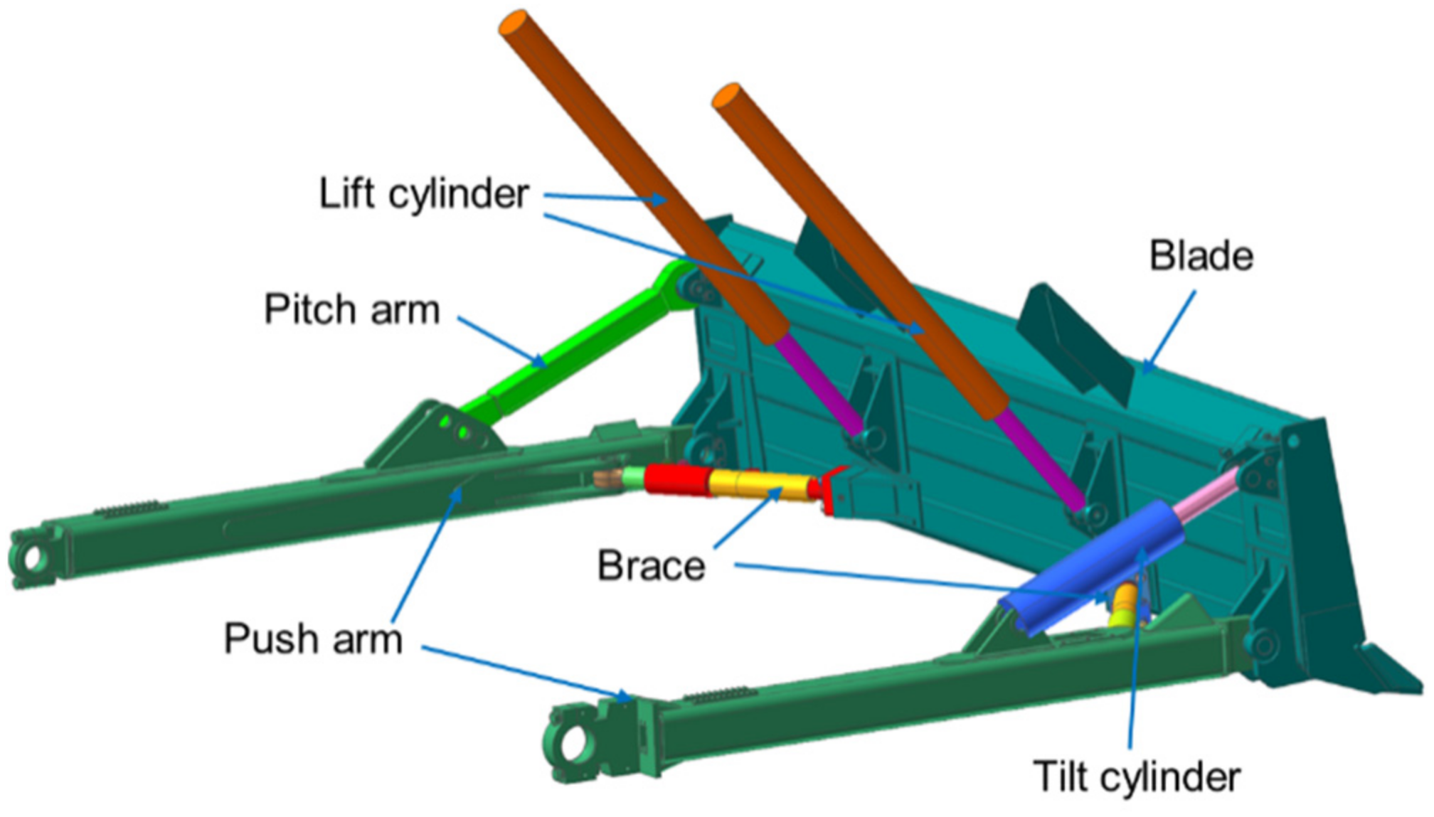
2.1. Dozer Dynamic Model

The response of components under actual working conditions can be predicted based on a high-fidelity MBD model [16]. The integrated dynamic model of the dozer, including the working device, track system, and frame, is created in this study using the RecurDyn software [17,18].
The working device model of the dozer is shown in Figure 1. The majority of the components in the working device model are constrained by spherical joints such that the blade can make three-dimensional movements, as is the case in reality. The push arms are connected to the pitch arm (tilt cylinder) and is braced through cylindrical pins with clearance fits in a real dozer. Spring forces with six degrees of freedom (DOFs) in [19] are used to model this clearance connection.
The finite element method (FEM) is a powerful numerical analysis technique for solving complex engineering problems [20]. Fatigue failure is caused by cumulative damage on the component surface under alternating external loads. Therefore, the push arms should be modelled as flexible bodies using FEM to analyze the damage on the element surfaces. In addition, soil loads act on the linkages of the working device through the blade during bulldozing, and the rigid blade model cannot deform as it does in reality. Thus, the blade is also required to be modelled as a flexible body to realize the accurate transfer of soil loads. Similarly, the pitch arm also must be modelled as a flexible body. Tetrahedron elements are used to mesh the components. Force-distributing rigid elements (FDR) [19] are used to connect the rigid and flexible components of the working device. The flexible blade, right push arm, left push arm, and pitch arm created contain 131,258, 12,007, 11,973, and 14,319 nodes, respectively.
The finite element components obtained are transformed into modal flexible bodies using modal reduction technology [21]. The modal flexible body method makes use of the modal vectors and coordinates of the deformed body to describe the elastic deformation, and the modes that contribute slightly to the deformation can be ignored. Therefore, the dynamic characteristics of the components can be described accurately using fewer modal DOFs, which greatly improves the calculation speed. On the premise of ensuring the accuracy of analysis, the first 47 modes of the push arms are considered in this paper. Figure 2 presents the first two mode shapes of the right push arm.
The track system model, which is comprised of track shoes, the track roller frame, the carrier roller, the sprocket, the idler, etc. [22], is created based on the parameters provided by the manufacturer. The constraint relationships among the components in the track system are established based on the RecurDyn_ LM module in RecurDyn [23,24].
Because the external loads acting on the push arms are not affected by the frame, the frame is modelled with simplification. The simplified frame features the same mass and centroid position as the actual frame. The complete dynamic model of the dozer is established by fixing the working device system and track system with the frame.
The overall space motion range of the created working device is consistent with reality. Figure 3 shows the rotation angle of the left and right push arms as the the blade tilts right to its maximum inclination. The included angles between the push arm and the ground are shown in Figure 3. Therefore, it is necessary to create a complete simulation model of the dozer and make a fatigue analysis of push arms under complete tilt bulldozing conditions.

2.2. Soil Model

An accurate soil model is a prerequisite for simulating the actual external loads. There are currently several methods for creating soil models, such as the particle FEM [25,26], material point method (MPM) [27,28], and DEM. The DEM considers the soil as a collection of discrete particles with certain shapes and masses and takes into consideration the interaction forces between the soil particles. Therefore, the DEM is used to model cohesive soil in this study.
The cohesive soil that exists in nature consists of particles with varying volumes, shapes, stiffness, moisture contents, and adhesion forces. Creating a soil model that exactly reflects the size, shape, and properties of the actual soil is impossible. However, soil particles can be created by scaling the size, approximating the shape, and calibrating the modelling parameters based on physical experiments. The reliability of this method has been confirmed in [29].
In reality, the majority of the soil particles comprise irregular clusters, which can be approximated by multiple spheres in a simulation. The greater the number of spheres used, the closer the simulated particle shape will be to that of real soil; however, the required amount of calculations increases. However, a small number of spheres would be insufficient to accurately simulate the geometric contact between the soil particles. Accordingly, a cluster sphere comprised of three spheres is used to model the soil particles. The maximum size of the established soil particles is 53 mm. The intrinsic parameters, contact parameters, and surface energy for the soil are then preliminarily set based on the soil properties of the dozer test site and the parameters calibrated in the literature [30]. Furthermore, the surface energy and contact parameters are calibrated based on the volume and shape of the soil when the blade contains a shovelful of soil in the experiment.
Finally, a soil bed comprising 1,100,000 particles is created based on the message of a single soil particle, which is a box with the length, width, and height of 20 m, 6 m, and 0.6 m, respectively.

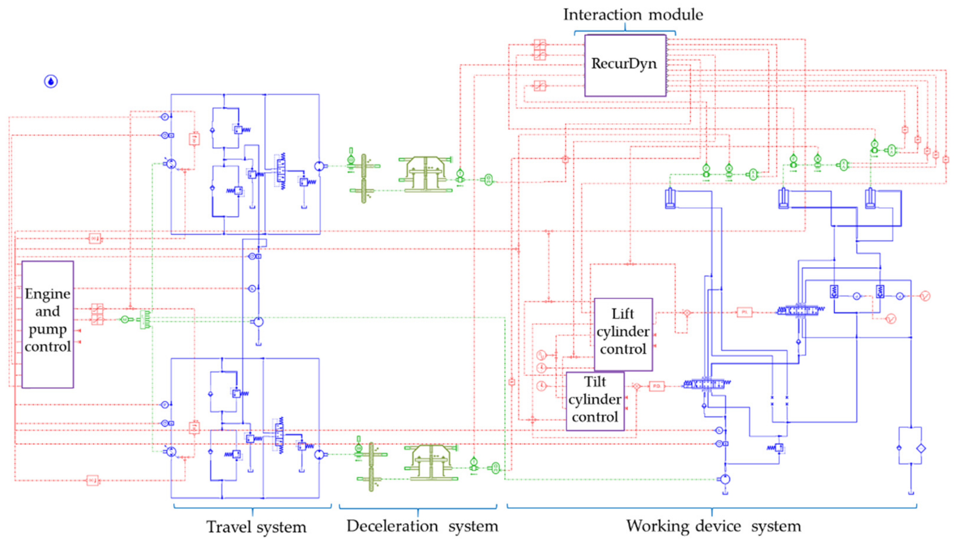
2.3. Control System Model

The control system is the key for dozers to work normally. The control system model, shown in Figure 4, is created based on the schematic of the actual hydraulic system and the control method of the working conditions for the dozer.
Because the dozer bears a large resistance torque during tilt bulldozing, the first gear is generally adopted to provide the maximum driving force. Under the first gear condition, the motors are maintained at the maximum displacements to ensure the maximum torque output, while the displacements of the walking pumps vary according to the external loads. Therefore, in this study, the travel control system of the dozer is simplified as a variable displacement pump and constant displacement motor system.
The travel control system is based on the dozer travel hydraulic system with the addition of engine speed and pump displacement control. The engine speed is adjusted by a constant power method, and the displacements of the variable pumps are varied by controlling their input currents. The details of the control logic are as follows. At the initial time, the engine speed is maintained at 0 to complete the blade tilt in the dozer stationary state. Then, the engine speed increases to the maximum value, and the displacements of the pumps also reach maximum values for the first gear condition. With increasing bulldozing resistance, the actual power of the system calculated using Equation (1) increases. When it exceeds the rated power of the engine, the engine speed is adjusted according to Equation (2), and the displacements of the pumps remain at the maximum values. Then, the engine speed remains unchanged as the engine speed is reduced by 100 rpm, and the displacements of the pumps are adjusted according to Equation (3). In this way, the actual power of the system changes near the rated power of the engine.
The power provided by the engine is converted into the output torque of the motor through the hydraulic system. Then, the torque is amplified by the deceleration system with a certain ratio and inputted into the sprockets of the dynamic model by the functional mock-up interface (FMI) [31], wherein the deceleration system is composed of a pair of spur gears and a planetary gear train.
P e s = P Q
where P e s is the actual power of hydraulic system and P and Q are the total pressure and total output flow of the hydraulic system, respectively.
n = 9550 P e 2 π P V
where n and P e are the speed and rated power of the engine, respectively. V is the total displacement of all pumps.
V p = P e Δ P e P p n
where V p is the displacement of travel pump. Δ P e is the actual power of hydraulic system other than travel system. P p is the total pressure of two travel pumps.
The working device control system is used to control the lift cylinders and tilt cylinder. The telescopic movements of the lift and tilt cylinders are controlled by calculating the differences between the target displacements and the actual displacements fed back from the dynamic model and then converting the deviations into control signals for reversing valves through the proportional–integral–derivative (PID) controller.
The target displacements of the cylinders are calculated according to the blade depth, slip rate, height of the blade right tip, lift cylinder stroke, and tilt cylinder stroke of the dynamic model extracted by the FMI. The slip rate of the dozer is calculated using Equation (4). The control details of the lift and tilt cylinders under the tilt bulldozing condition can be divided into the following five stages:
(1)
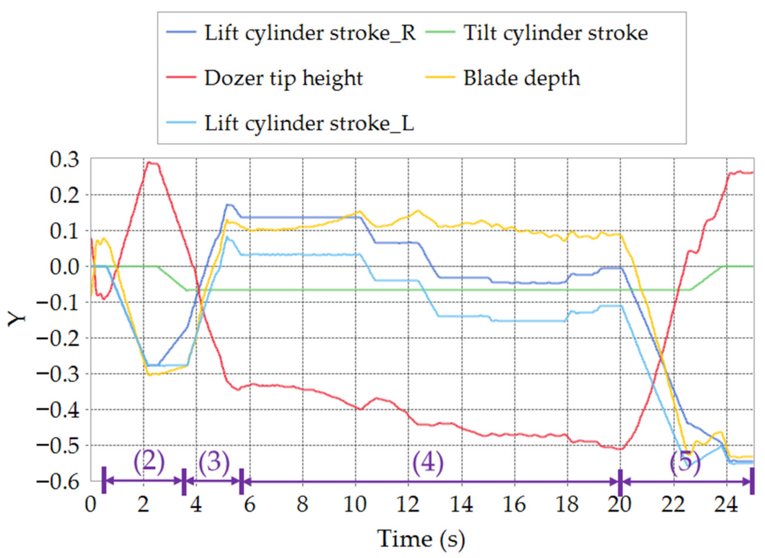
Initial stage. All the oil cylinders remain stationary to ensure the stability of the system within the first 0.5 s;
(2)
Blade lifting and tilting stage. The lift cylinders retract at the speed of 0.2 m/s to lift the blade. Then, the lift cylinders remain stationary as the blade is 0.3 m above the ground. Subsequently, the tilt cylinder retracts at a speed of 0.2 m/s to make the blade tilt right to its maximum inclination;
(3)
Soil cutting stage. The lift cylinders extend at a speed of 0.25 m/s to lower the blade for cutting soil. Then the lift cylinders remain stationary to collect the soil as the blade depth (distance from the ground to the middle of the blade lower edge) reaches 0.13 m;
(4)
Soil collection stage. The movement of the lift cylinders is controlled according to the real-time detected blade depth and the slip rate, such that the soil can be collected within the target depth range, i.e., 0.08 m to 0.16 m, and within the specified slip rate range, i.e., less than 0.3. The speed of the lift cylinders is 0.13 m/s;
(5)
Soil unloading stage. The lift cylinders retract at a speed of 0.5 m/s for unloading the soil, as the simulation time is greater than 20 s. When the blade is lifted, the right tip is 0.03 m above the ground and the tilt cylinder retracts at the speed of 0.3 m/s to rotate the blade back.
s = w r v w r
where s represents slip rate of the dozer track, w and v are angular velocity of sprocket and forward speed of the dozer, respectively, and r is pitch radius of the sprocket.

3. Fatigue Analysis

The push arm of the dozer is made of a square steel pipe welded with supporting plates. The material of the push arms is HF50_10 steel, which is defined according to the SAE J1099 standard [32]. The material parameters are illustrated in Table 1.
The push arms of the dozer are subjected to complex alternating and random loads during bulldozing. The load-time histories of the push arms should first be obtained to calculate the fatigue damage. There are two types of load-time histories in a fatigue analysis: stress-based and strain-based. Since the fatigue of the dozer components is a low-stress and long-life problem, i.e., high-cycle fatigue, stress-based fatigue analysis methods are required.
A complete cycle of the tilt bulldozing conditions is simulated by RecurDyn–EDEM–AMESim co-simulation, which includes blade lifting, blade tilting, soil cutting, soil collection with a fixed blade depth, and soil unloading. The stress–time histories of the push arms under the action of soil loads and the mechanism system are obtained based on the rigid–flexible coupling technique. Then, the damage and fatigue lives of the push arms are calculated using fatigue theory.

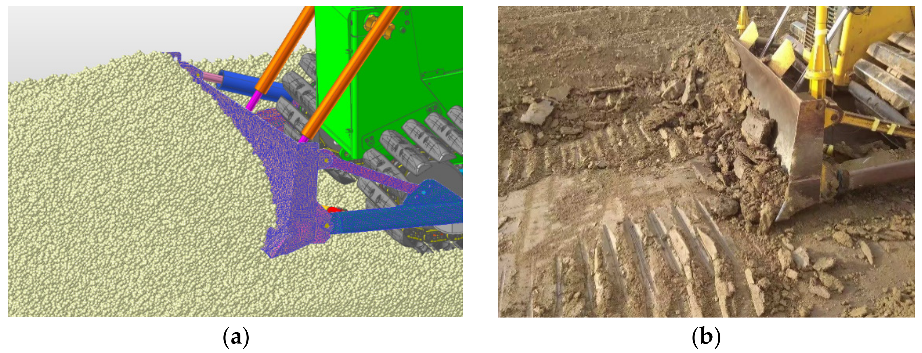
3.1. Co-Simulation Results

Figure 5 presents the cylinder strokes, blade depth, and height of the right tip of the blade in the simulation. The purple numbers in the figure represent the corresponding stages in Section 2.3. It can be observed that the oil cylinders in the simulation move completely in accordance with the control strategy of the control system. The blade depth is successfully controlled within the target range of 0.08 m to 0.16 m. Figure 6 presents the soil load borne by the blade and the front joint forces of the push arms in the forward direction. It can be observed that, with increasing soil volume in front of the blade, the soil load increases continuously, and the soil load reaches a maximum value of 78,888 N at 19.75 s. Furthermore, the trend in the variation of the front joint force of the right push arm is similar to the soil load, and the magnitude of this variation is also close to the soil load. Therefore, the soil loads in the forward direction under the tilt bulldozing conditions are mainly borne by the push arm on the blade tilted side.
The stress contours of the push arms under the maximum stress state occur at the beginning of the soil unloading and are presented in Figure 7. It can be observed that the maximum stress on the right push arm is 52.47 MPa, which appears at the rear of the supporting plate connected with the tilt cylinder. The maximum stress on the left push arm occurs at the rear of the supporting plate connected to the left brace. The stresses acting on the upper surface of the right push arm behind the tilt cylinder are also greater than those in other areas. Since the maximum stresses do not coincide with welded joints, the influence caused by the change of material properties can be neglected in the later analysis [33]. The maximum stresses of the push arms are due to the large bending moment caused by the instantaneous acceleration of the blade lifting. However, the maximum stresses are far less than the yield stress of the push arms.
The initiation and propagation of cracks occur on the structure surface. Thus, the structural stresses obtained by finite element analysis need to be transformed into the stresses on the element surface by the tensor transformation method. The stress–time histories of the most damaged surfaces of the push arms are presented in Figure 8. As the initial 0.5 s of the simulation is for the system to reach stability, the stress data for the initial 0.5 s is neglected. It can be observed that, in the soil cutting stage, owing to the small soil loads, the push arms bend significantly under the thrust of the cylinder, and the stresses are thus large. As the soil loads increase, the push arms bend downward less until they start to bend upward under the effect of the soil. Therefore, the compressive stress of the left push arm changes to tensile stress, and the tensile stress of the right push arm changes to compressive stress. With the increase in the soil loads, the stresses gradually increase until they reach their maximum value during unloading. Finally, with the decrease in the soil volume in front of the blade, the stresses decrease rapidly to close to 0.

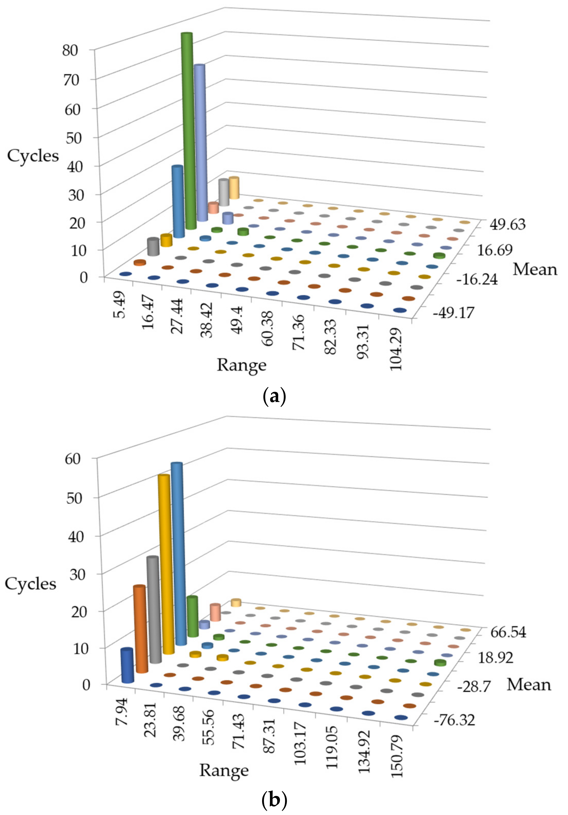
3.2. Rain Flow Counting
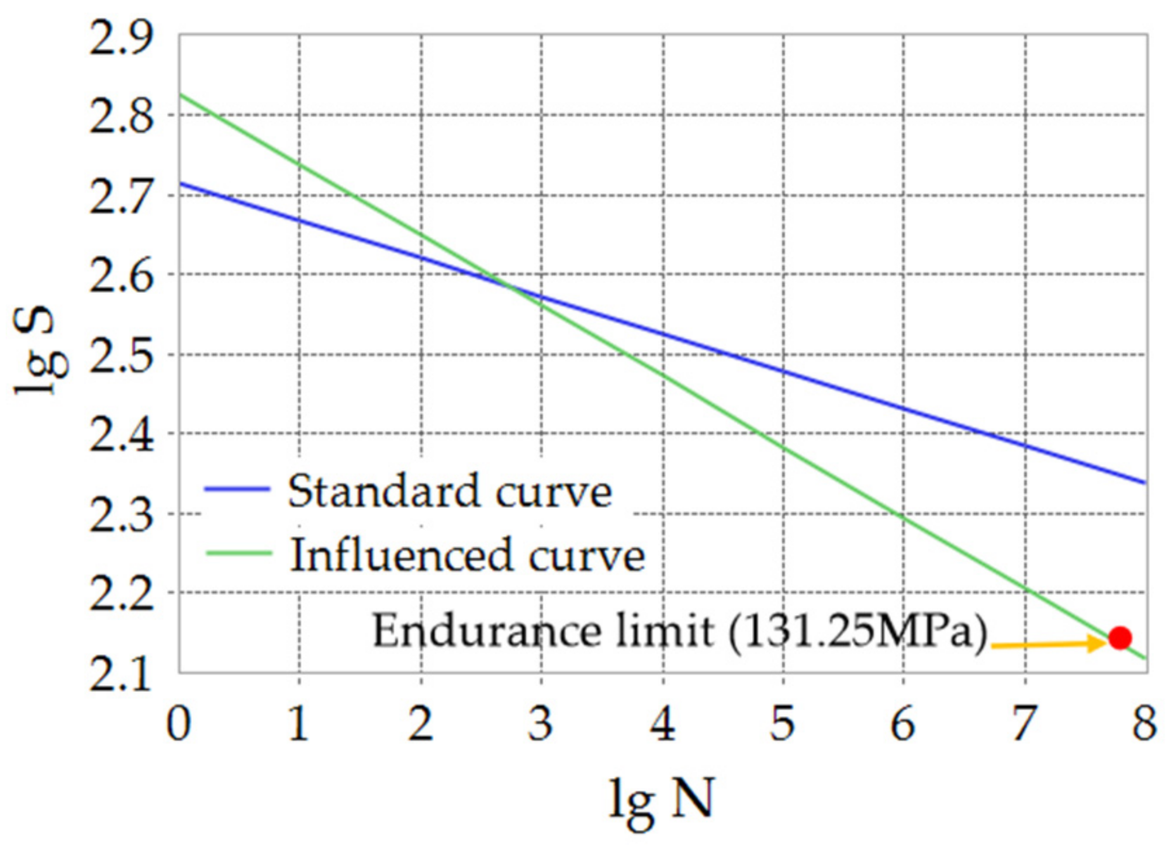
It can be concluded from the stresses in Figure 8 that the push arms of the dozer are subjected to random loads during tilt bulldozing. The life prediction based on the S–N curve requires the external loads to be cyclic. Thus, the random loads should be converted into cyclic loads with variable amplitudes using the counting method. The rain flow counting [34] method is most commonly used in fatigue analysis because it is practical and follows the stress–strain hysteresis loop. The rain flow counting method assumes that the random load spectrum is a repeated load–time history based on typical load spectrum blocks. The random load spectrum can be converted into a variable-amplitude load spectrum comprising a series of load cycles by identifying all the load cycles contained in typical load spectrum blocks. Figure 9 presents the cycle graph of the stress amplitude and mean stress obtained after the rain flow counting for the stress–time history in Figure 8. As the variation range of the stress amplitude in the stress–time history of the push arms is small, the cycles in Figure 9 do not change significantly with the stress amplitudes.

3.3. S-N Curve

The fatigue analysis of the components should be based on the S–N curve. The S–N curve reflects the relationship between the applied stress and the fatigue life of the component. As the push arms are subject to high-cycle fatigue, the S–N curve is drawn based on the Masson–Coffin life criterion. The Masson–Coffin life equation is expressed as shown in Equation (5). The S–N curves of the push arms in double logarithmic form are presented in Figure 10. The blue curve in the figure represents the standard S–N curve without considering the influence of fatigue factors, including the notch factor, surface factor, size factor, load factor, etc. The green curve represents the curve considering fatigue factors. Since for the push arms, the stress concentration caused by welding and the surface quality have a greater impact on the fatigue analysis, the green S–N curve is calculated by defining the notch factor as 1.2, the surface factor as 0.9, and the other factors as 1 in the RecurDyn software.
Δ σ 2 = σ f ( 2 N f ) b
where Δ σ 2 is normal stress amplitude for a cycle, σ f is the fatigue strength coefficient, 2 N f is the reversals to failure, and b is the fatigue strength exponent.
As the S–N curve only reflects the fatigue life of the components subjected to symmetrical cyclic stresses, it is difficult for it to work well if the mean stress value is non-zero and the stress amplitude is not large. Thus, the S–N curve is modified using the Goodman method to transform the non-zero mean stress into an equivalent symmetric stress, as shown in Equation (6).
σ a S e + σ m S u = 1
where σ a is the stress amplitude, S e is the effective alternating stress at failure for a lifetime, S u is the ultimate strength, and σ m is the mean normal stress for a cycle.

3.4. Fatigue Life Calculation

Fatigue failure is caused by the accumulation of fatigue damage generated by a series of alternating loads. Components are damaged under any stress, and such damage is permanent and cumulative. Fatigue failure occurs as the accumulated damage causes the component to approach its fatigue life limit [35]. The linear damage accumulation theory proposes that the damage caused by each stress is independent and can be linearly accumulated. The linear cumulative damage theory significantly simplifies the fatigue mechanism, and its calculation is simple and accurate. Therefore, the linear fatigue damage theory (Palmgren–Miner damage criterion) [36] is used to calculate the total damage and fatigue life of the push arms. The Palmgren–Miner criterion defines the total damage of the material as D; similarly, the damage caused by a certain load cycle is D i = 1 N i , and the total damage caused by n cycles is calculated using Equation (7).
D = i = 1 n n i N i
where N i is the fatigue life of components under σ i and n i is the number of cycles under σ i .
It can be identified from Equation (8) that the left and right push arms will suffer fatigue failure after 4,670,992 and 53,768 cycles, respectively. Accordingly, the fatigue lives of the left and right push arms are 39,381.89 h and 7,317.84 h, respectively, under the continuous tilt bulldozing condition with a maximum soil resistance of 78,888 N. The service life of the right push arm is about 18.58% that of the left arm. Therefore, the tilt bulldozing conditions cause great damage to the push arm on the blade tilted side and reduce its service life by 81.42% compared with the other side. Therefore, in tilt bulldozing conditions, it is necessary to make the blade tilt left and right alternately for bulldozing. The greater the inclination of the blade, the greater the bending moment borne by the push arms. Thus, to reduce the occurrence of cracks, working conditions that cause the blade to tilt to the maximum inclination should be minimized.
λ = 1 D
where λ represents the fatigue life.
Figure 11 presents the life contours and damage distributions of the push arms. The parts with the shortest service lives are indicated in red, and the parts with the longest service lives are indicated in blue. It can be concluded that the rear parts of the supporting plates connected with the pitch arm and tilt cylinder on the push arms are most prone to generate cracks. Therefore, these positions should be optimized to reduce stress concentration [33].

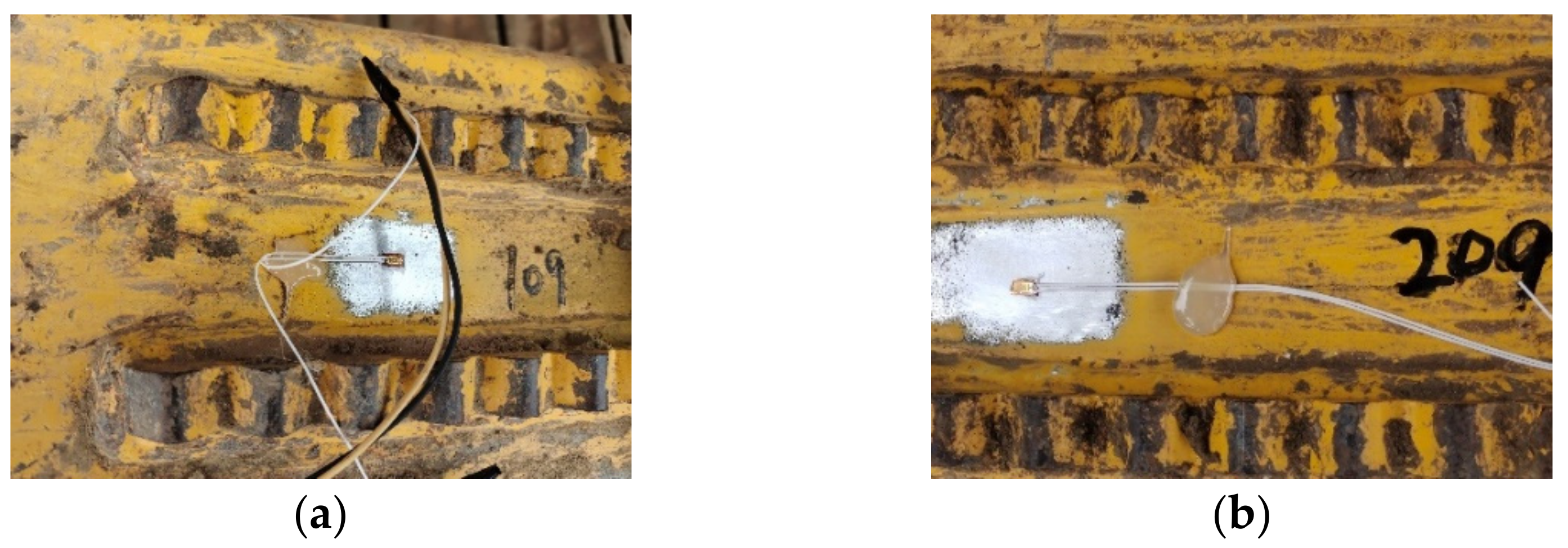
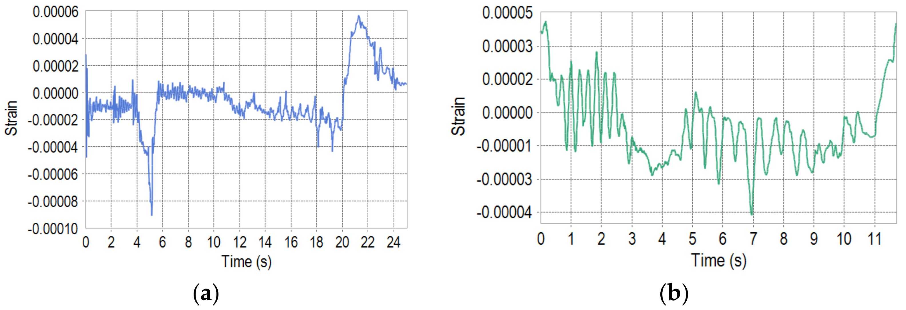
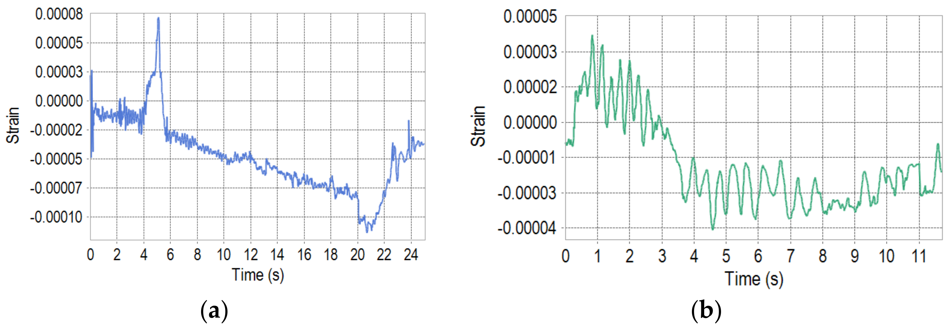
4. Experimental Verification

A tilt bulldozing experiment is developed to verify the accuracy of the simulation model. The strains on the upper surface of the push arms at a distance of about 515 mm from the rear joints are measured using strain gauges, as shown in Figure 12. The reason is that these positions are far away from the tilt cylinder; therefore, the strains will not be affected by the oil pressure. Additionally, there are no welding parts around, so the effects of stress concentrations can be disregarded. Figure 13 shows the complete dozer after installing the strain gauges.
At the beginning of the experiment, the dozer lifts and tilts the blade in situ and then moves to the bulldozing area for bulldozing. The bulldozing process includes continuous soil cutting, soil collection with a fixed blade depth, and soil unloading without the blade rotating backwards. Each bulldozing cycle lasts approximately 12 s. The target blade depth range is 0.08 m to 0.16 m. When the dozer slips significantly, the blade is lifted until the dozer moves forward normally. Then, the blade is lowered again for soil collection. As the blade depth and slip rate are controlled by the driver based on their operational experience, it is difficult for the operation to be completely consistent with that of the simulation. Figure 14a,b present the side view of the soil in front of the blade in the simulation and experiment, respectively. It can be observed that the soil shape and volume at the front of the blade in the simulation are almost identical to those in the experiment.
Figure 15 and Figure 16 present the push-arm strains obtained from the simulation and experiment. Because the ground is not even in the experiment, the time cost of the tilt bulldozing condition, which includes the soil cutting, soil collection, soil transfer and unloading stages, is not easy for the driver to control. Thus, the time scale of the figures in simulation does not match well with the experiment. Since the soil in the experiment is compacted under the action of rain and external forces, the soil blocks are generated as the blade cuts the soil. Thus, the soil loads acting on the blade are discontinuous and uneven. Although the bond method [37] can model the compacted soil, the number of soil particles are about 1,100,000 herein, and thus, too much calculation time is needed. Therefore, the soil model in the simulation is modeled as a discrete particle group with adhesion, which means that the soil loads acting on the blade are relatively uniform and continuous. Additionally, the ground on which the dozer travels in the experiment is not as flat as that in simulation, resulting in a little tremor of the push arms. Therefore, the strains in the experiment have larger oscillations than those in the simulation.
Additionally, as it is difficult for the speed of cutting soil in the experiment to be identical to the simulation, there are some differences between the strains during the soil cutting stages in the simulation and the experiment. In the stability stage of the soil collection, the strain of the left push arm in the experiment is approximately −0.00001, and in the simulation, this value is approximately −0.000013. In the same stage, the measured strain of the right push arm is approximately −0.00003; the simulated strain increases with the soil load, and the maximum compressive strain is −0.00008. The strains of the push arms in the simulation and experiment can be considered as approximately identical ignoring the influence of the cylinder speed, shovel depth, and slip rate. It can be concluded that the simulation model used in this study is consistent with the actual dozer system. Accordingly, the fatigue analysis results based on the co-simulation model are reliable.

5. Conclusions

Due to unbalanced loading, tilt bulldozing is one of the most damaging working conditions for dozer push arms. Traditional fatigue analysis methods with specific postures and known loads are unable to fully reflect the fatigue lives of push arms featuring multiple postures, and fatigue analysis based on tests is cumbersome and difficult to realize. With the use of virtual simulation technology, this paper presents a fatigue analysis method for dozer push arms under tilt bulldozing conditions. The contributions of this paper are as follows:
(1)
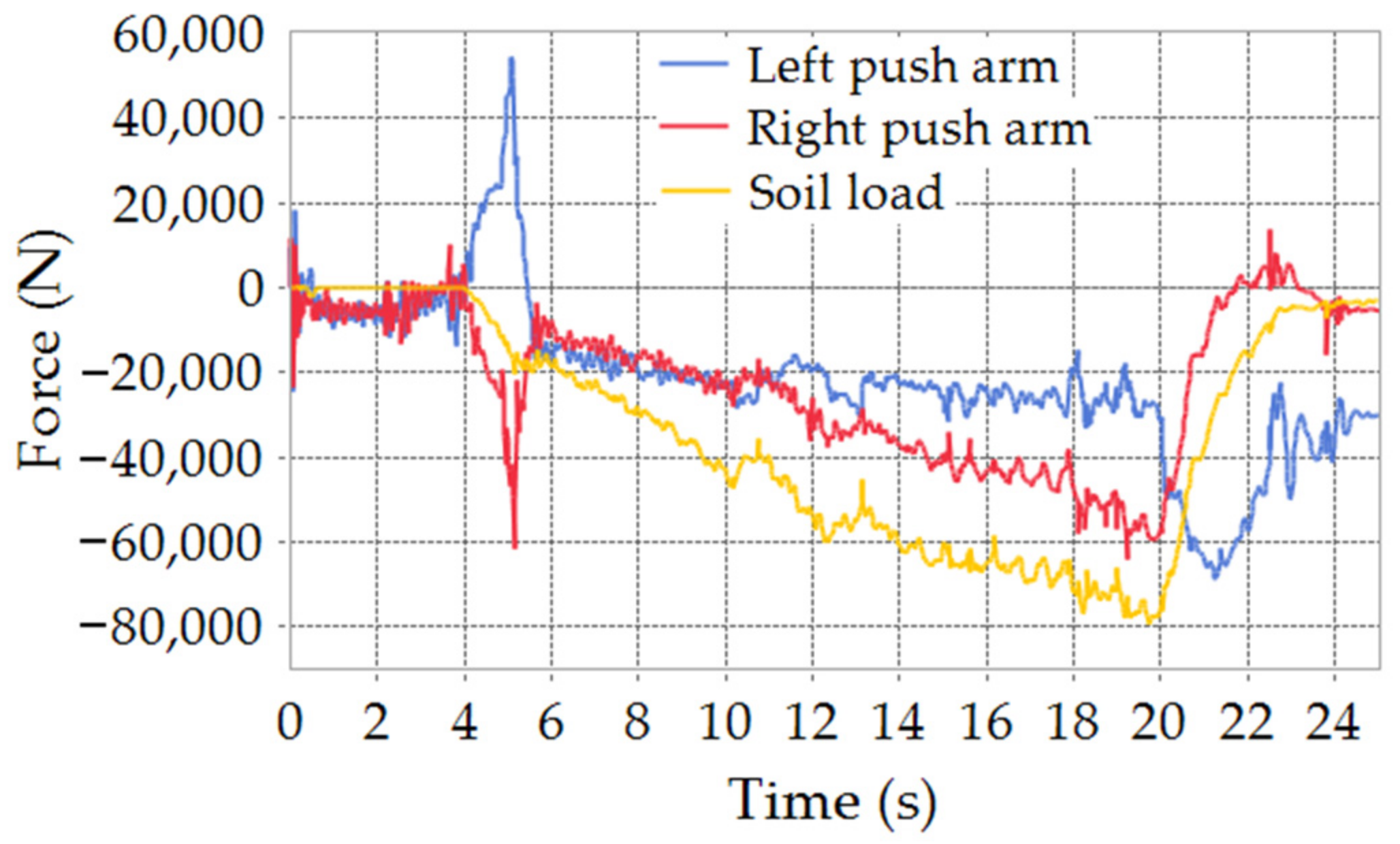
The soil loads acting on the dozer components are calculated based on the established dozer dynamic model and soil model. The soil loads acting on the blade are accurately transferred to the push arms;
(2)
Considering the influence of the hydraulic pressure on the forces of push arms, a control system model of the dozer is established, which can accomplish the working-mode control actually realized by driver in combination with the electronic and hydraulic systems;
(3)
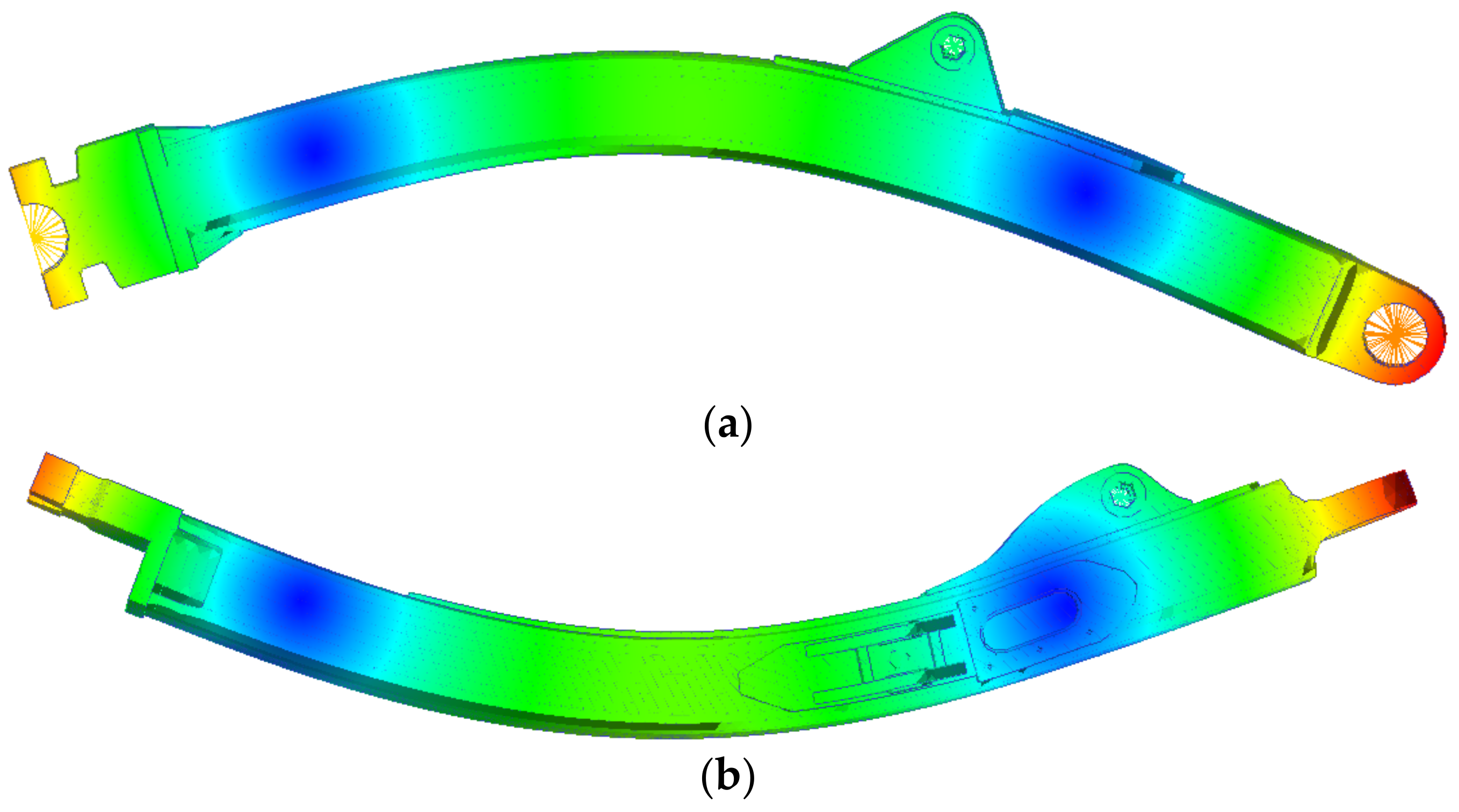
The push arms are analyzed in an integrated dozer system, which circumvents the inaccuracy involved in imposing simplified constraint forces;
(4)
The stress–time histories of the push arms are obtained under the complete tilt bulldozing conditions based on RecurDyn–EDEM–AMESim co-simulation, which effectively circumvents the deficiency of static fatigue analysis methods with specific boundary conditions and loading histories;
(5)
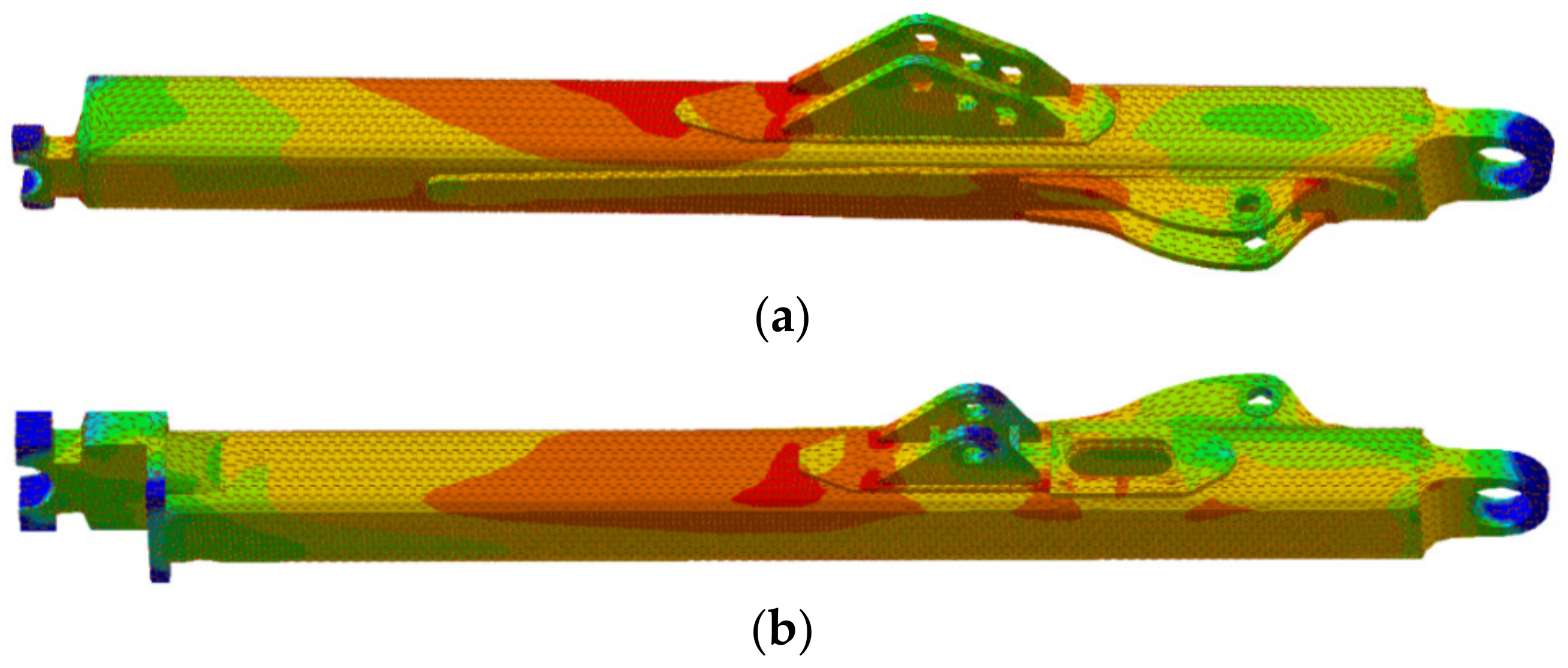
The overall damage of the push arms is analyzed by using Palmgren–Miner criterion, and the fatigue lives of the most damaged positions are predicted instead of predicting the lives of specified positions according to experience in traditional methods;
(6)
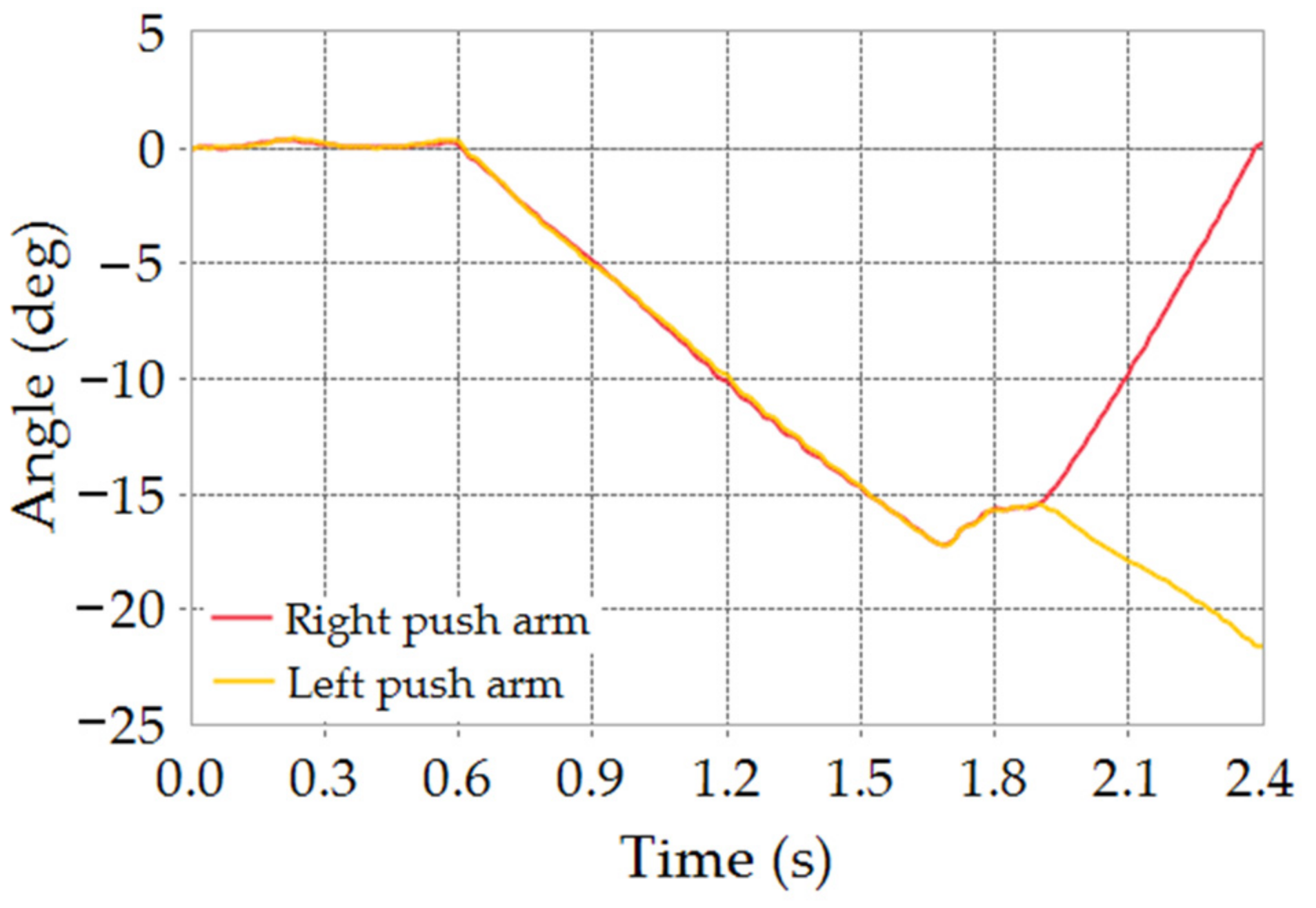
The stresses and fatigue lives of the left and right push arms under tilt bulldozing conditions are compared. It is concluded that the service lives of the left and right push arms are 39381.89 h and 7317.84 h, respectively, with a maximum bulldozing resistance of 78888 N. The service life of the right push arm is 81.42% shorter than that of the left push arm.
Furthermore, the proposed fatigue analysis method visualizes the fatigue life field, which provides a more accurate model for the discovery of dangerous areas in dynamic machinery and is conducive to the reliability design and optimization of the push arms. In addition, the proposed method is efficient and simple and provides an important reference for the fatigue analysis of other components.

Author Contributions

Conceptualization, X.Z., writing—original draft preparation, L.P.; methodology, X.Z. and L.P.; software, J.-H.C.; validation, L.P., X.L. and X.G.; investigation, X.G.; resources, X.Z. and R.Z.; data curation, X.G.; supervision, X.Z. and Y.H.; project administration, R.Z. and Y.H. All authors have read and agreed to the published version of the manuscript.

Funding

This research was supported by National Natural Science Foundation of China (Grant No.51909145).

Institutional Review Board Statement

Not applicable.

Informed Consent Statement

Not applicable.

Data Availability Statement

Not applicable.

Acknowledgments

This work was supported by the Key Laboratory of High-efficiency and Clean Mechanical Manufacture at Shandong University, Ministry of Education; the National Demonstration Center for Experimental Mechanical Engineering Education at Shandong University; the Young Scholars of Shandong University and Rizhao Intelligent Manufacturing Institute; and the Fundamental Research Funds of Shandong University. The authors would like to acknowledge FunctionBay Inc. for providing the license file of the RecurDyn software.

Conflicts of Interest

The authors declare no conflict of interest.

References

  1. Geng, L.; Luo, G.; Zhang, Z.; Yang, X.; Wu, D. Fatigue life analysis and structure performance improvement of bulldozer working device based on ANSYS. In Proceedings of the 2017 IEEE 3rd Information Technology and Mechatronics Engineering Conference (ITOEC), Chongqing, China, 3–5 October 2017. [Google Scholar]
  2. Choi, K.; Cho, J. Durability Study on Damage at the Front Side of Bulldozer due to Fatigue Load by Using Finite Element Method. Int. Inf. Inst. (Tokyo) Inf. 2017, 20, 3593–3601. [Google Scholar]
  3. Ding, Q.X.; Tian, Y.C.; Chen, J.; Chen, J.W.; Hui, K.L.; Yin, H.W. Estimation of Fatigue Life for Hydraulic Excavator Boom under All Operating States. Adv. Mater. Res. 2011, 199–200, 463–469. [Google Scholar] [CrossRef]
  4. Zhao, H.; Wang, G.; Wang, H.; Bi, Q.; Li, X. Fatigue life analysis of crawler chain link of excavator. Eng. Fail. Anal. 2017, 79, 737–748. [Google Scholar] [CrossRef]
  5. Wu, Z.Y.; Gao, Y.D.; Xu, Z.; Wang, S.F. Modeling and Simulation of Tracked Vehicle Based on Pro/E and RecurDyn. In Proceedings of the 5th International Conference on Advanced Design and Manufacturing Engineering, Shenzhen, China, 19–20 September 2015. [Google Scholar] [CrossRef] [Green Version]
  6. Cleary, P.W. DEM modelling of particulate flow in a screw feeder. Prog. Comput. Fluid Dyn. Int. J. 2007, 7, 128–138. [Google Scholar] [CrossRef]
  7. Bischoff, M.; Onate, E.; Owen, D.R.J.; Ramm, E. A discrete element model for cohesive soil. In Proceedings of the III International Conference on Particle-Based Methods: Fundamentals and applications (PARTICLES 2013), Stuttgart, Germany, 18–20 September 2013. [Google Scholar]
  8. Tsuji, T.; Nakagawa, Y.; Matsumoto, N.; Kadono, Y.; Takayama, T.; Tanaka, T. 3-D DEM simulation of cohesive soil-pushing behavior by bulldozer blade. J. Terramechanics 2012, 49, 37–47. [Google Scholar] [CrossRef]
  9. Li, X.; Duan, C.; Bai, K.; Yao, Z. Operating Performance of Pure Electric Loaders with Different Types of Motors Based on Simulation Analysis. Energies 2021, 14, 617. [Google Scholar] [CrossRef]
  10. Shin, Y.J.; Jeong, J.S.; Jun, C.W.; Sohn, J.H. Interacting analysis between wheel and sand particles based on DEM and its validation with experiments. J. Mech. Sci. Technol. 2020, 34, 4537–4544. [Google Scholar] [CrossRef]
  11. Cheng, K.; Zhang, J.; Dai, Q.L.; Wang, P.Y.; Zhang, J. Modeling and Simulation of Hybrid Hydraulic Excavator Based on AMESim. Appl. Mech. Mater. 2010, 29–32, 2071–2075. [Google Scholar] [CrossRef]
  12. Park, S.H.; Alam, K.; Jeong, Y.M.; Chang, D.L.; Yang, S.Y. Modeling and simulation of hydraulic system for a wheel loader using AMESim. In Proceedings of the ICCAS-SICE, Fukuoka, Japan, 18–21 August 2009. [Google Scholar]
  13. Xu, F.; Liu, X.; Chen, W.; Zhou, C.; Cao, B. Modeling and co-simulation based on Adams and AMESim of pivot steering system. J. Eng. 2018, 2019, 392–396. [Google Scholar] [CrossRef]
  14. Bin, X.S.C. Modelling and stability investigation of a rigid flexible coupling system. Acta Mech. Sin. 1997, 4, 56–64. [Google Scholar]
  15. Hong, J. Advances in dynamics of rigid-flexible coupling system. J. Dyn. Control. 2004, 2, 3–8. [Google Scholar]
  16. Selech, J.; Ulbrich, D.; Włodarczyk, K.; Staszak, Ż.; Marcinkiewicz, J.; Romek, D.; Baran, B. A working design of a bulldozer blade as additional equipment of a compaction drum roller. In Proceedings of the MATEC Web of Conferences, Wuhan, China, 22–24 October 2019; p. 04005. [Google Scholar] [CrossRef]
  17. Jeong, H.; Yu, J.; Lee, D. Track HM Design for Dynamic Analysis of 4-tracked Vehicle on Rough Terrain Using Recurdyn. Trans. Korean Soc. Mech. Eng. A 2021, 45, 275–283. [Google Scholar] [CrossRef]
  18. Gummer, A.; Sauer, B. Modeling planar slider-crank mechanisms with clearance joints in RecurDyn. Multibody Syst. Dyn. 2014, 31, 127–145. [Google Scholar] [CrossRef]
  19. Pan, L.; Zhu, X.; Li, Y.; Guan, T. Lightweight design of an electric tricycle frame considering dynamic stress in driving conditions. Int. J. Automot. Technol. 2021, 22, 1075–1085. [Google Scholar] [CrossRef]
  20. Rusiński, E.; Harnatkiewicz, P.; Kowalczyk, M.; Moczko, P. Examination of the causes of a bucket wheel fracture in a bucket wheel excavator. Eng. Fail. Anal. 2010, 17, 1300–1312. [Google Scholar] [CrossRef]
  21. Khulief, Y.; Mohiuddin, M. On the dynamic analysis of rotors using modal reduction. Finite Elem. Anal. Des. 1997, 26, 41–55. [Google Scholar] [CrossRef]
  22. Li, L.; Du, B.; Li, J.S.; Chen, S.; Yang, F.; Qi, D. Simulation Analysis of Centroid Offset of Electric Drive Bulldozer Based on Recur Dyn. DEStech Transactions on Computer Science and Engineering. 2018. Available online: https://www.destechpub.com/product/destech-transactions-computer-science-engineering/ (accessed on 15 November 2021).
  23. LU, J.; Wei, L.; Zhao, T. Dynamic simulation of tracked vehicle turning at high speed based on RecurDyn. Mod. Mach. 2008, 1, 13–15. [Google Scholar]
  24. Choi, J.; Ryu, H.; Bae, D.; Huh, G.; Park, D. Dynamic track tension of high mobility tracked vehicles. In Proceedings of the International Design Engineering Technical Conferences and Computers and Information in Engineering Conference, Pittsburgh, PA, USA, 9–12 September 2001; pp. 61–67. [Google Scholar]
  25. Idelsohn, S.R.; Onate, E.; Del Pin, F. The particle finite element method: A powerful tool to solve incompressible flows with free-surfaces and breaking waves. Int. J. Numer. Methods Eng. 2004, 61, 964–989. [Google Scholar] [CrossRef] [Green Version]
  26. Oñate, E.; Celigueta, M.A.; Idelsohn, S.R.; Salazar, F.; Suárez, B. Possibilities of the particle finite element method for fluid–soil–structure interaction problems. Comput. Mech. 2011, 48, 307. [Google Scholar] [CrossRef]
  27. Stomakhin, A.; Schroeder, C.; Chai, L.; Teran, J.; Selle, A. A material point method for snow simulation. ACM Trans. Graph. (TOG) 2013, 32, 102. [Google Scholar]
  28. Al-Kafaji, I. Formulation of a Dynamic Material Point Method (MPM) for Geomechanical Problems; Institute of Geotechnical Engineering, University of Stuttgart: Stuttgart, Germany, 2013. [Google Scholar] [CrossRef]
  29. Ucgul, M.; Fielke, J.M.; Saunders, C. Defining the effect of sweep tillage tool cutting edge geometry on tillage forces using 3D discrete element modelling. Inf. Processing Agric. 2015, 2, 130–141. [Google Scholar] [CrossRef] [Green Version]
  30. Tekeste, M.Z.; Way, T.R.; Syed, Z.; Schafer, R.L. Modeling soil-bulldozer blade interaction using the discrete element method (DEM). J. Terramechanics 2020, 88, 41–52. [Google Scholar] [CrossRef]
  31. Richter, C.; Roessler, T.; Otto, H.; Katterfeld, A. Coupled discrete element and multibody simulation, part I implementation, verification and validation—ScienceDirect. Powder Technol. 2020, 379, 494–504. [Google Scholar] [CrossRef]
  32. Engineers, S.o.A. SAE J1099. Rev. 2002. Available online: https://www.docin.com/p-1750860016.html (accessed on 15 November 2021).
  33. Zinchenko, A.; Baiul, K.; Krot, P.; Khudyakov, A.; Vashchenko, S.; Banasiewicz, A.; Wróblewski, A. Materials Selection and Design Options Analysis for a Centrifugal Fan Impeller in a Horizontal Conveyor Dryer. Materials 2021, 14, 6696. [Google Scholar] [CrossRef]
  34. Glinka, G.; Kam, J. Rainflow counting algorithm for very long stress histories. Int. J. Fatigue 1987, 9, 223–228. [Google Scholar] [CrossRef]
  35. Dharmadhikari, S.; Bhattacharya, C.; Ray, A.; Basak, A. A Data-Driven Framework for Early-Stage Fatigue Damage Detection in Aluminum Alloys Using Ultrasonic Sensors. Machines 2021, 9, 211. [Google Scholar] [CrossRef]
  36. Fisher, J.W.; Kulak, G.L.; Smith, I.F. A Fatigue Primer for Structural Engineers; National Steel Bridge Alliance, American Institute of Steel Construction: Chicago, IL, USA, 1998. [Google Scholar]
  37. Tamas, K. The role of bond and damping in the discrete element model of soil-sweep interaction. Biosyst. Eng. 2018, 169, 57–70. [Google Scholar] [CrossRef]
Figure 1. Working device of the dozer.
Machines 10 00038 g001
Figure 2. Mode shapes of the right push arm: (a) the first mode shape; (b) the second mode shape.
Machines 10 00038 g002
Figure 3. Rotation angles of the push arms.
Machines 10 00038 g003
Figure 4. Control system model.
Machines 10 00038 g004
Figure 5. Cylinder strokes and blade heights.
Machines 10 00038 g005
Figure 6. Soil load and joint forces.
Machines 10 00038 g006
Figure 7. Stress contours: (a) left push arm; (b) right push arm.
Machines 10 00038 g007
Figure 8. Stress-time histories of push arms: (a) left push arm; (b) right push arm.
Machines 10 00038 g008
Figure 9. Rain flowing counting results: (a) left push arm; (b) right push arm.
Machines 10 00038 g009
Figure 10. S–N curve of push arms.
Machines 10 00038 g010
Figure 11. Life contour and damage distribution: (a) left push arm; (b) right push arm.
Machines 10 00038 g011
Figure 12. Strain gauges in experiment: (a) left push arm; (b) right push arm.
Machines 10 00038 g012
Figure 13. The complete dozer after installing the strain gauges.
Machines 10 00038 g013
Figure 14. Comparison of the soil views in front of the blade: (a) in the simulation; (b) in the experiment.
Machines 10 00038 g014
Figure 15. Strains of the left push arm: (a) simulation results; (b) experiment results.
Machines 10 00038 g015
Figure 16. Strains of the right push arm: (a) simulation results; (b) experiment results.
Machines 10 00038 g016
Table 1. Parameters of HF50_10 steel.
Yield Stress (MPa)Ultimate Stress (MPa)Fatigue Strength CoefficientFatigue Strength ExponentFatigue Ductility CoefficientFatigue Ductility ExponentCyclic Strength CoefficientCyclic Strength Hardening Exponent
357490536−0.0474.118−0.8834810.049
Publisher’s Note: MDPI stays neutral with regard to jurisdictional claims in published maps and institutional affiliations.

