Abstract
In order to recover and utilize the potential energy of mining trucks efficiently, this paper proposes a nested optimization method of a novel energy storage system. By analyzing the multi-objective optimization problem of the oil-circulating hydro-pneumatic energy storage system, a nested optimization method based on the advanced adaptive Metamodel-based global optimization algorithm is carried out. Research shows that this method only requires a short time to solve the complex nonlinear hybrid optimization problem and achieves better results. The optimized energy storage system has higher system efficiency, energy density, and volume utilization rate, thus obtaining a smaller system volume and weight. Verified by the bench experiment of its powertrain, the hydro-pneumatic hybrid mining truck with the optimized energy storage system significantly reduces its fuel consumption and CO2 emission. Thus, it lays the foundation for the practical application of hydro-pneumatic hybrid mining trucks.
1. Introduction
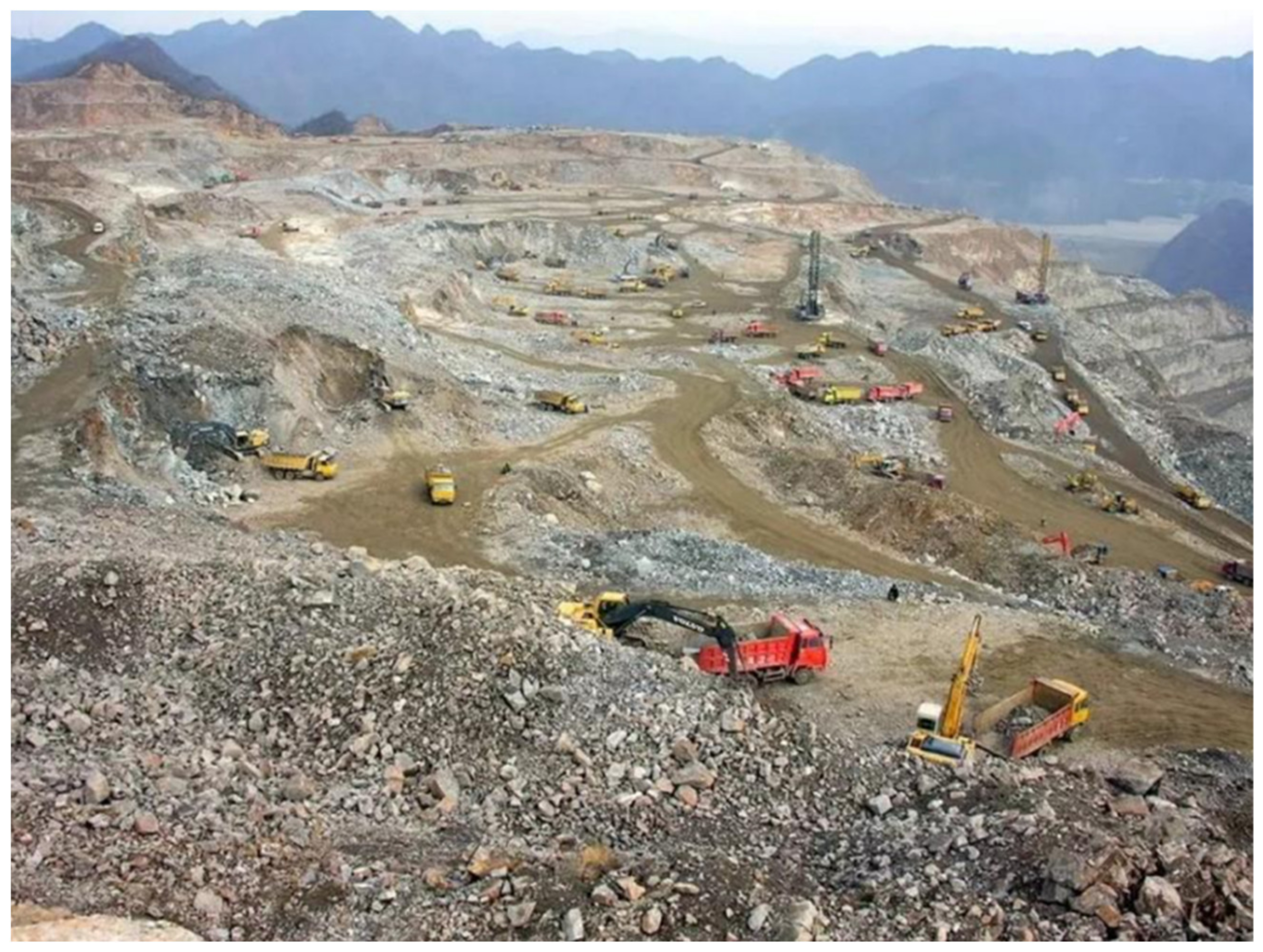
Electric-drive mining trucks have heavy loading capacity and high transportation efficiencies [1], as shown in Figure 1. They are widely used in large-scale open-pit mines and construction sites, as shown in Figure 2. Unlike on-road trucks, off-road mining trucks work at fixed routes [2]. They are usually driven 4–5 km uphill along a slope of 9%–12% grade with a full load, and then driven downhill without load [3]. Since they have enormous curb weight, the recoverable potential energy is substantial when going downhill [4]. In the downhill process, the mechanical braking energy is transformed into regenerative electricity by traction motors, and then fed into the braking resistance to generate heat, which dissipates in the air [5]. It is a waste of energy. Thus, it is important to develop a feasible energy storage system (ESS) that could recover this energy in the downhill process, and then reuse it in the uphill process [6]. It could significantly reduce fuel consumption and CO2 emission in the mining industry.
There is already some research on hybrid mining trucks with battery ESSs aiming to recover this energy. Ehsan et al. [7] summarize the current research and applications of hybrid mining trucks. The study points out that the ESS for hybrid mining trucks requires a large capacity. Thus, it could recover more potential energy, especially in cases of heavy curb weight, long-distance and large slopes. Tim et al. [8] carry out a prototype test of a modified hybrid mining truck. This experiment concludes that the current battery technology is the main obstacle for practical applications. It results from the high cost and short lifespan of battery ESSs [9].
Besides, open-pit mines in China are mainly distributed in high latitudes, where the seasonal temperatures vary large [10]. In some of them, the temperatures in winter can reach −30 °C or even −40 °C. The low temperature will reduce the battery performance and affect the recovery of potential energy [11]. Meanwhile, high-power charging or discharging at low temperatures will accelerate the degradation of the battery [12], resulting in a high cost of the hybrid mining truck with a battery ESS [13].
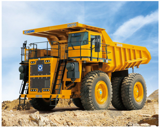
Figure 1.
A mining truck of XCMG [14].
Figure 1.
A mining truck of XCMG [14].

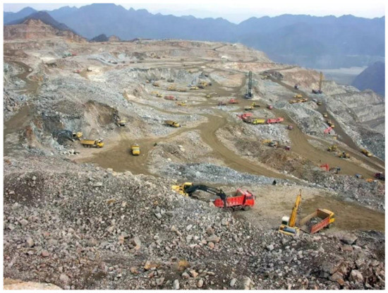
Figure 2.
Mining trucks working at an open-pit mine.
Figure 2.
Mining trucks working at an open-pit mine.
Considering the shortcomings of the current battery, Chun et al. [15] explore alternative technique routes beyond battery ESS. They propose a comparative study of hybrid mining trucks with different ESSs. It includes battery ESS, hydraulic ESS, supercapacitor ESS, and compressed-air ESS. The paper concludes that the hybrid mining trucks with hydraulic ESS and compressed-air ESS have better economic benefits than battery ESS. Moreover, based on the current hydraulic and compressed-air ESS technologies, the oil-circulating hydro-pneumatic energy storage system (OHESS) has been carried out in recent studies [16,17]. The results show that the hybrid mining trucks with OHESS could achieve a better performance for potential energy recovery than regular hydraulic or compressed-air ESSs.
Despite OHESS’s advantages, its complex structure, discontinuous operation method, and multiple dynamic heat transfer process, all lead to a complex nonlinear hybrid system [17]. For the optimal structural design to increase the system efficiency and energy density, it results in a complex black-box optimization problem. So, an efficient optimization method is needed. Furthermore, for most ESSs, the structure and energy management strategy (EMS) are coupled together [18]. The structure optimization is based on the corresponding optimal EMS, and the EMS optimization should be founded on the corresponding optimal structure. So, the overall optimization should consider both the optimal design and optimal control at the same time and optimize the two together to obtain the optimal scheme of OHESS. Thus, a nested optimization method with the two is required.
Aiming at the coupling optimization problem of the structure and EMS of ESS, some scholars establish a multi-objective optimization analysis model and obtain the normalized optimization objectives. A nested double-layer optimization method is adopted, with the EMS in the inner layer, and the structure in the outer layer, to obtain the optimal scheme of the ESS. Song et al. [19] carried out a multi-objective optimization framework for the hybrid ESS of battery and supercapacitor, and obtained the trade-off solution of two contradictory objectives on the Pareto front. Hung et al. [20] propose a nested optimization method for hybrid ESSs. It takes the maximum energy storage capacity and minimum fuel consumption as the two optimization goals, through a nested optimization method, obtains an optimal scheme. The results show that the scheme could effectively reduce fuel consumption and CO2 emission at a minimal system cost.
For complex nonlinear optimization problems, the appropriate optimization algorithm that could search out the global optimal solution quickly and efficiently is the key issue [21]. Genetic algorithm (GA), as a classical global optimization algorithm, has been widely used in many applications [22]. GA simulates the natural evolution and selection process [23]. It has the advantages of a simple process and strong scalability [24], and can be applied to gray-box and even black-box problems [25]. However, GA iteratively searches for the optimal solution by populations, which significantly increases the number of function evaluations (NFE), resulting in slow convergence and large computation costs [26]. Thus, the Metamodel-based global optimization method is proposed to solve the complex nonlinear optimization problems [27]. By integrating the Metamodel into the searching process, it significantly reduces the NFE of the complex nonlinear functions and concentrates on the most promising region of the global optimum [28]. As an efficient Metamodel-based algorithm, the adaptive Metamodel-based global optimization (AMGO) has been developed in recent research [29]. It is designed for solving highly nonlinear hybrid black-box optimization problems like OHESS. Through the adaptive hybrid Metamodel of kriging and augmented radial basis function, it could intelligently determine the most suitable Metamodel function, so as to solve the optimization problem efficiently.
The traditional optimization methods for ESSs fail to solve the complex nonlinear optimization problem of OHESS. In this paper, a nested optimization method of OHESS based on the advanced AMGO algorithm is presented for the potential energy recovery of hybrid mining trucks. This paper brings contributions in the field of mining trucks, which are shown as follows:
- The powertrain configuration of the hydro-pneumatic hybrid electric-drive mining truck with OHESS is carried out and analyzed, as a way to recover the potential energy of mining trucks when going downhill;
- The experimental platform of the mining truck’s powertrain is developed. By this means, the actual recovery power in the downhill process and fuel consumption in the uphill process could be accurately measured for further optimization and analysis;
- A nested optimization method is put forward for the OHESS of hybrid mining trucks. Based on the advanced AMGO algorithm, the complex nonlinear hybrid optimization problem is solved with a lower computation cost. Compared with the multi-objective comprehensive scheme, better optimization results of OHESS are obtained by the nested method, which could significantly reduce the fuel consumption and the corresponding CO2 emission of mining trucks.
The next sections are organized as follows: Section 2 introduces the powertrain configuration of the hydro-pneumatic hybrid electric-drive mining truck, and the structure, operation method, and characteristics of OHESS. Section 3 presents the working cycle test of the mining truck and the bench experiment of its powertrain. Section 4 details the analysis of the multi-objective optimization problem of OHESS. Section 5 carries out the nested optimization method of OHESS and analyzes the results. Section 6 draws conclusions.
2. Hydro-Pneumatic Hybrid Electric-Drive Mining Truck
This section introduces the powertrain configuration of the hydro-pneumatic hybrid electric-drive mining truck, and the structure, operation method, and characteristics of OHESS.
2.1. Powertrain of the Hybrid Electric-Drive Mining Truck
The powertrain of regular electric-drive mining trucks is composed of engine, generator, traction motors, braking resistance, and electric power converters, as shown in Figure 3. In the uphill process, the engine outputs mechanical power into the generator, which is transformed into alternating electric power. After the rectification and inversion, the retransformed alternating electric power drives the traction motors to provide the traction torque that the truck needs. While in the downhill process, the traction motors provide regenerative brake torque. The braking resistance transforms the regenerative electricity into heat that dissipates in the air, while the engine is idling to keep the cooling and hydraulic systems functioning.

Figure 3.
Powertrain of regular electric-drive mining trucks.
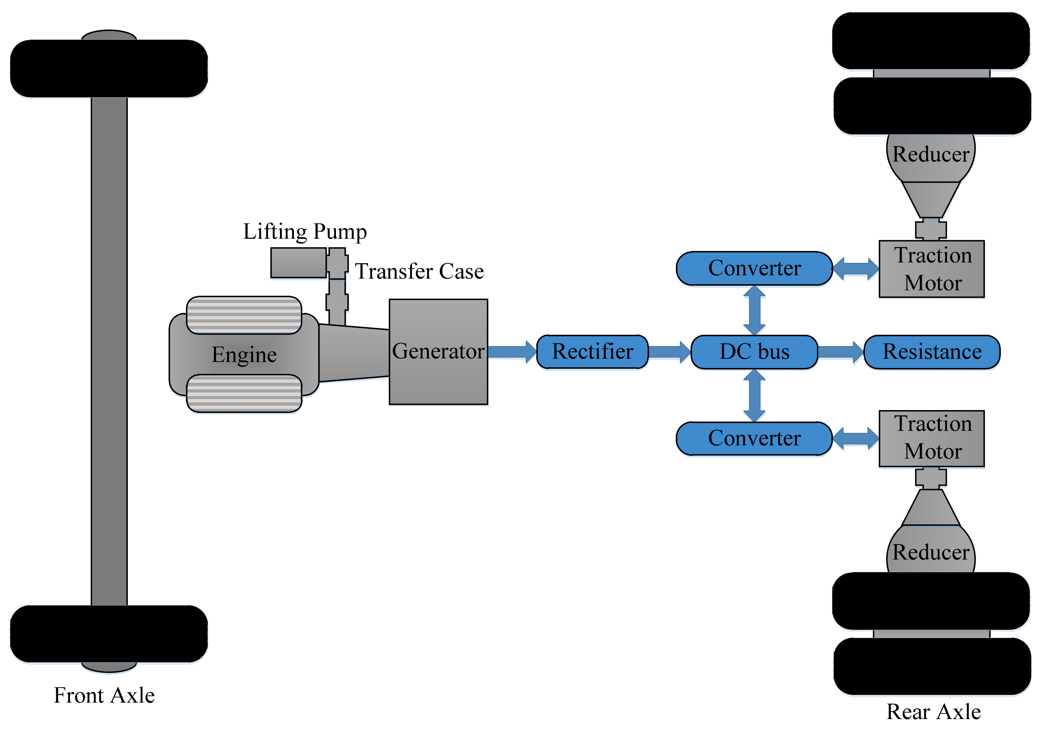
Different from the regular powertrain configuration shown in Figure 3, the powertrain of the hydro-pneumatic hybrid electric-drive mining truck adopts OHESS to recover the downhill potential energy rather than dissipate it, as shown in Figure 4. Thus, most braking resistance is omitted, leaving only some of it for special cases. In the downhill process, the traction motors transform the mechanical braking power into alternating electric power. After the rectification and inversion, the retransformed alternating electric power drives the generator (works at motor mode) and then is transformed to mechanical power again. As the generator is mechanically connected with the engine that connects the OHESS via a transfer case, part of the mechanical energy reversely drags the engine without fuel injection to keep the auxiliary systems functioning, and the rest is recovered by OHESS. Since the lifting pump is not working in this process and has a rated power larger than the reverse dragging power, it can be used as an energy conversion device of OHESS. While in the uphill process, the power flow is similar to that in the powertrain of regular mining trucks. The difference lies in the power source. In the hybrid powertrain, the engine and OHESS jointly output mechanical power rather than the sole engine. The engine provides the main required traction power, and OHESS supplies the rest.
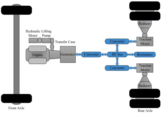
Figure 4.
Powertrain of the hydro-pneumatic hybrid electric-drive mining truck.
2.2. Oil-Circulating Hydro-Pneumatic Energy Storage System
This section presents the system structure of OHESS and details its operation method. In addition, its energy storage characteristics are analyzed.
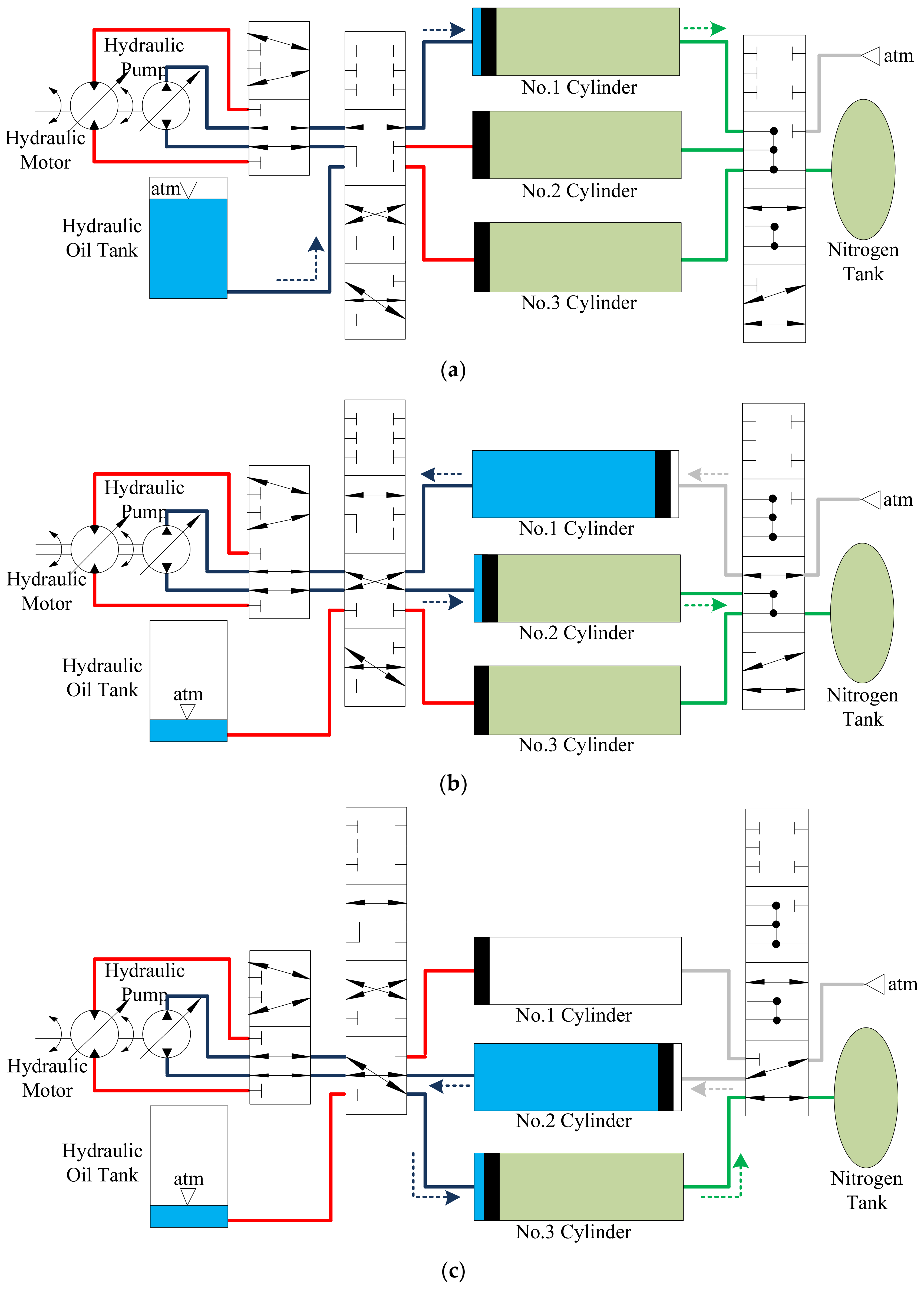
Different from regular hydraulic ESSs, the OHESS, combining the layouts of hydraulic and compressed-air ESSs, is a novel compact hydro-pneumatic ESS that only needs a small proportion of hydraulic oil [16]. As a special pressure ESS with the oil-circulating layout, the OHESS has plural accumulators rather than a sole one and the accumulator number could be arbitrary. The operation method of OHESS is shown in Figure 5, which is a 3-accumulator one. Figure 5a presents the recovering stage I when the piston in the No.1 cylinder is running right. The nitrogen is compressed into the nitrogen tank while the hydraulic oil enters the No.1 cylinder. Figure 5b presents the recovering stage II when the piston in the No.2 cylinder is running right. The process within is similar to the No.1 cylinder in the recovering stage I, while now the air enters the No.1 cylinder and its piston is running left. Figure 5c presents the recovering stage III, which is similar to stage II. After the three recovering stages, all nitrogen is compressed into the nitrogen tank and vice versa for the releasing stages.

Figure 5.
Operation method of OHESS: (a) Recovering stage I (Releasing stage III); (b) Recovering II (Releasing stage II); (c) Recovering stage III (Releasing stage I) [17].
The regular hydraulic ESS and the OHESS with the same energy storage capacity were compared in a previous work [17], which indicates that the OHESS requires a lower amount of hydraulic oil and system installation space. Figure 6 presents the system and oil volume ratios of OHESS to regular hydraulic ESS. It shows that the OHESS with ten accumulators accounts for only 10% of oil and 64.78% of installation space of the regular counterpart’s. Therefore, it is an appropriate ESS for the potential energy recovery of hybrid mining trucks.
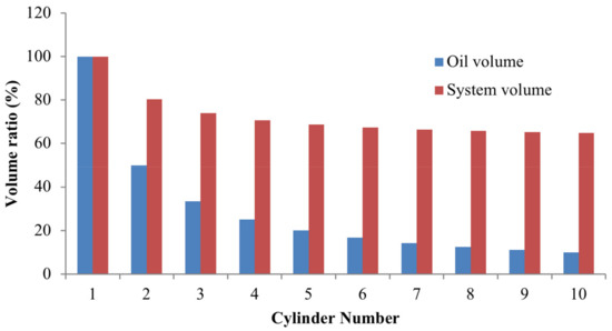
Figure 6.
The system and oil volume ratio of OHESS to regular hydraulic ESS [17].
3. Working Cycle Test and Bench Experiment of the Mining Truck
Aiming at the hybrid electric-drive mining truck with OHESS introduced in Section 2, this section presents the working cycle test of the mining truck and the bench experiment of its powertrain for further optimization research.
3.1. Working Cycle Test of the Mining Truck
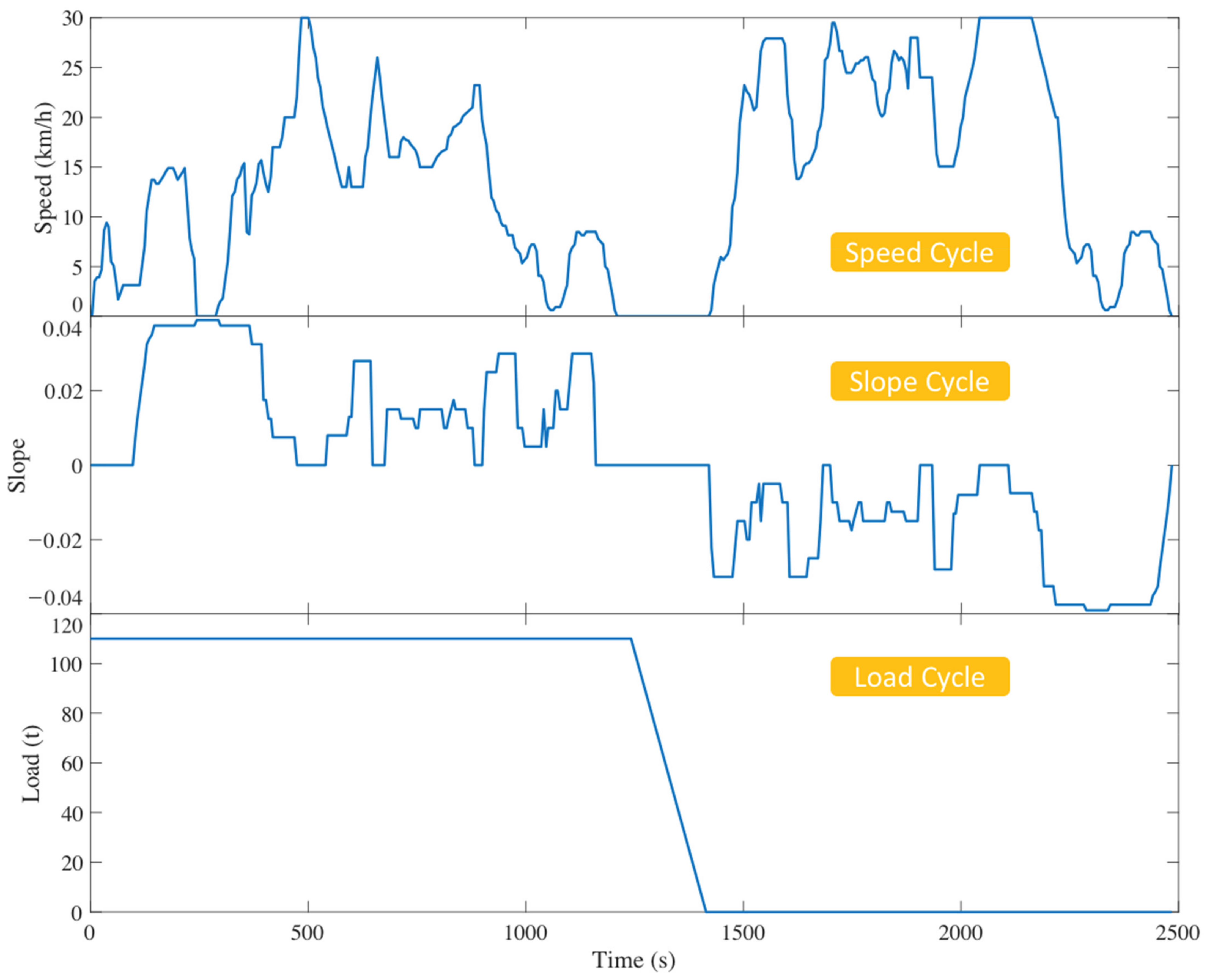
Electric-drive mining trucks usually work at fixed routes. Their typical working cycle is shown in Figure 7, including the following four stages:
- A-B: The mining truck is started at the loading point with a full load, and driven uphill to the unloading point;
- B-C: The mining truck stops, and unloads the ores when the lifting pump is functioning;
- C-D: After the unloading process, the mining truck is started without load, and is driven downhill to the loading point. In this stage, the traction motors provide regenerative brake torque and the braking resistance transform the regenerative electricity into heat, when the engine is idling to keep the cooling and hydraulic systems functioning;
- D-A: The mining truck stops and waits for the ores to be loaded again.
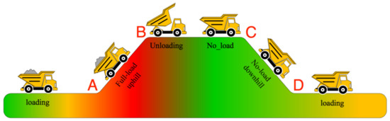
Figure 7.
The transportation route of the mining truck [2].
Figure 7.
The transportation route of the mining truck [2].

As shown in Figure 8, our team took the XDE110 of XCMG, a 110 t electric-drive mining truck, as the experimental target vehicle, whose specifications are shown in Table 1 [7]. Then they carried out its working cycle test on a route of an open-pit mine in Heihe, China, whose results are presented in Figure 9. The parameters of the actual working cycle are listed in Table 1.
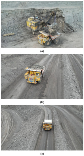
Figure 8.
Working cycle test of the mining truck: (a) Loading process of the mining truck; (b) Uphill process with full load; (c) Downhill process without load.

Table 1.
Parameters in Working Cycle Test of the Mining Truck.
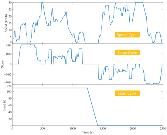
Figure 9.
Actual working cycle of the target mining truck.
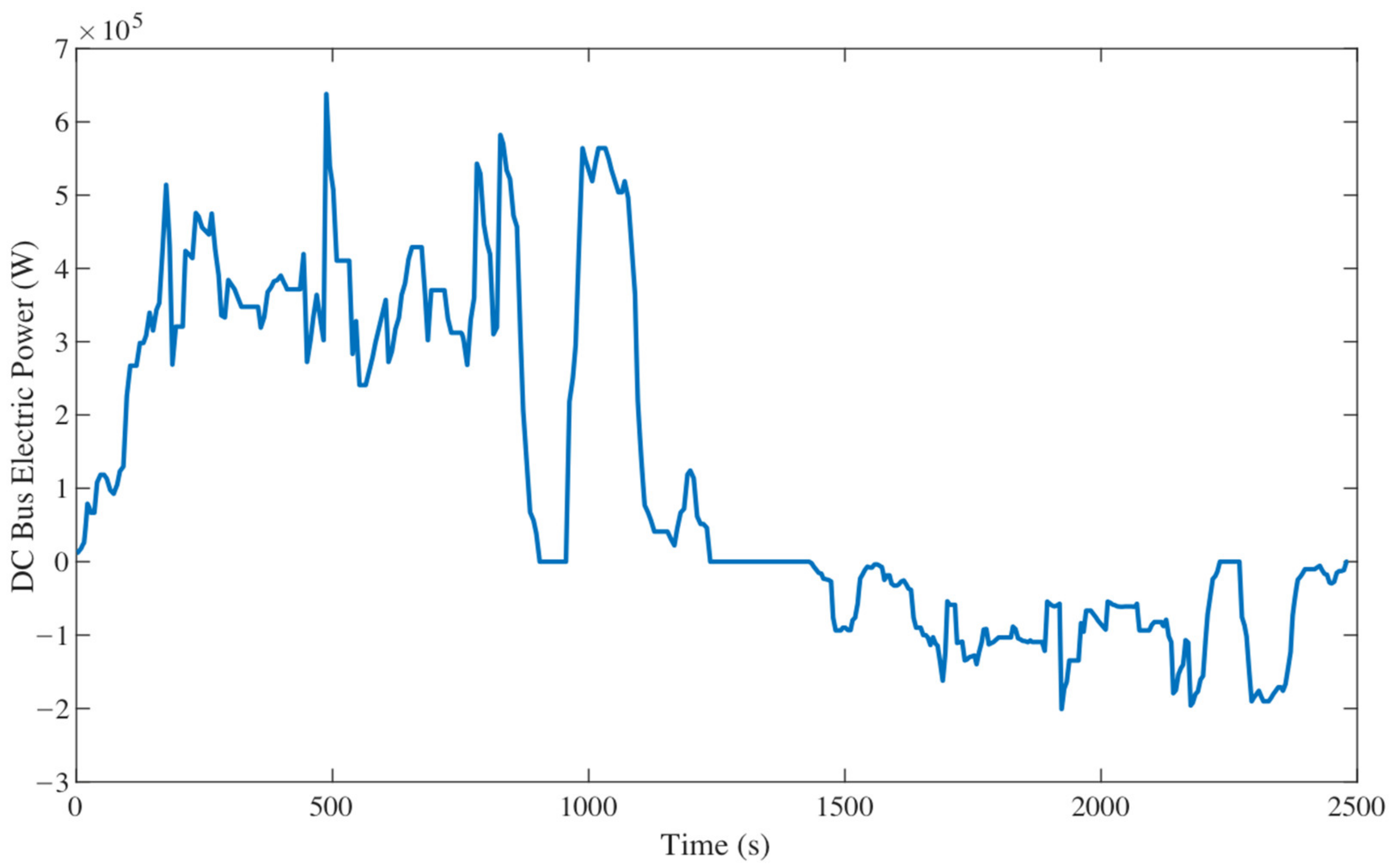
In the working cycle test, the DC bus voltage and current of the electric-drive mining truck were measured. So that the electric braking and traction power could be calculated for further simulation and experiments, as shown in Figure 10.
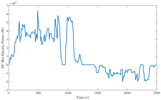
Figure 10.
The DC bus electric power of the electric-drive mining truck.
3.2. Bench Experiment of the Mining Truck’s Powertrain
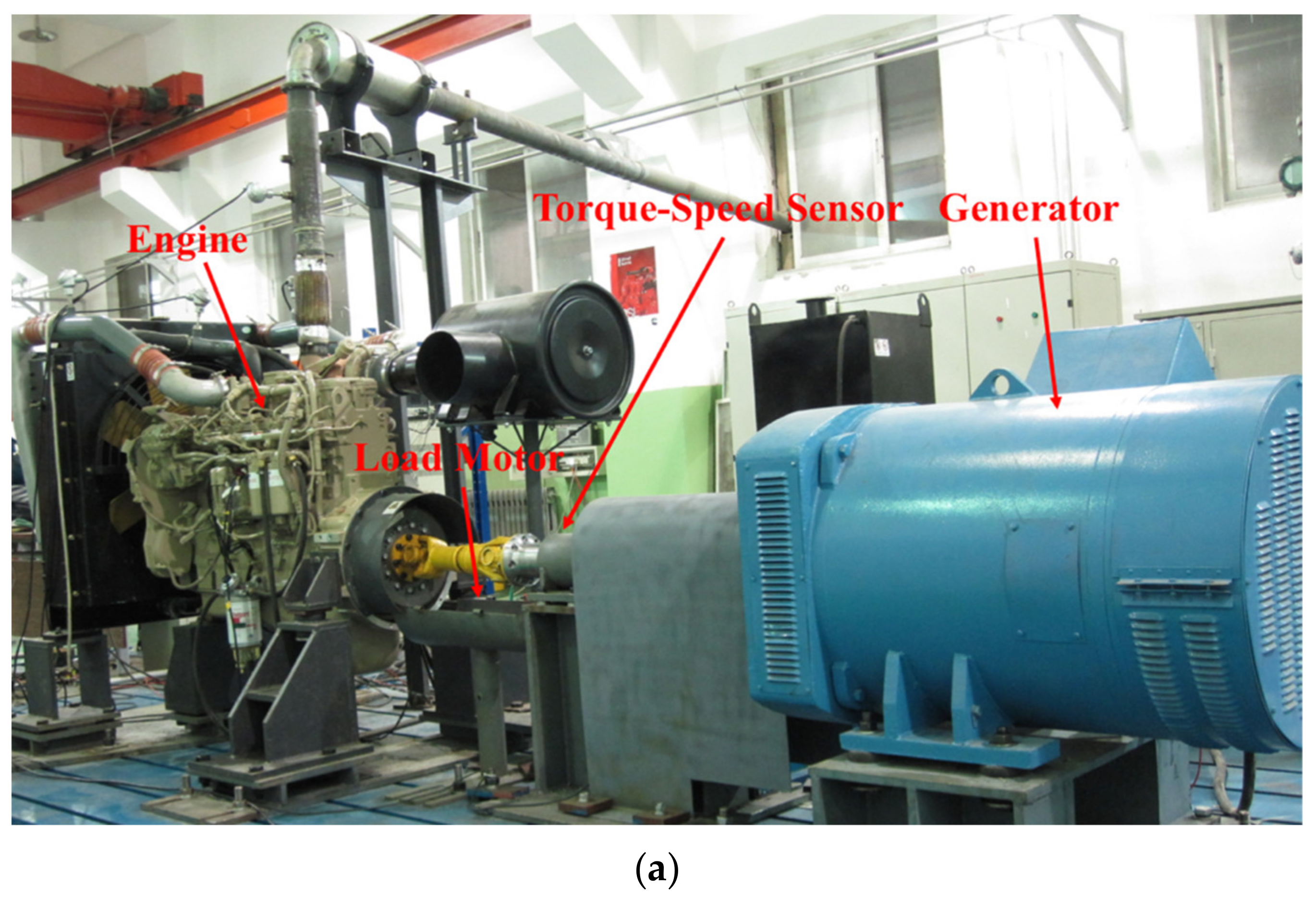
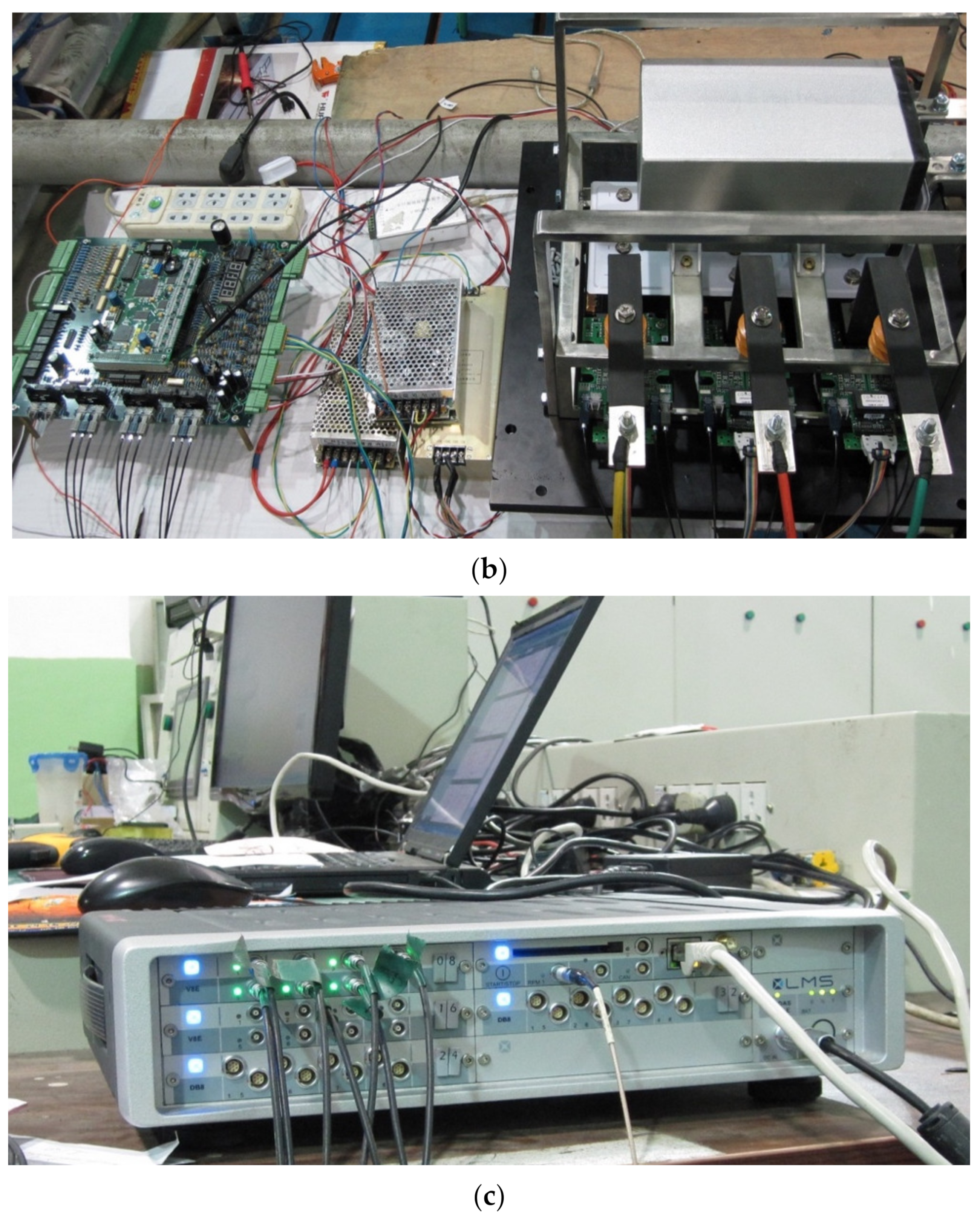
To measure the actual recovery power of the OHESS of the mining truck in the downhill process and analyze the influence of the EMS on the vehicle fuel consumption in the uphill process, our team built an experimental platform for the powertrain of the target electric-drive mining truck. The structural diagram of the experiment is shown in Figure 11.
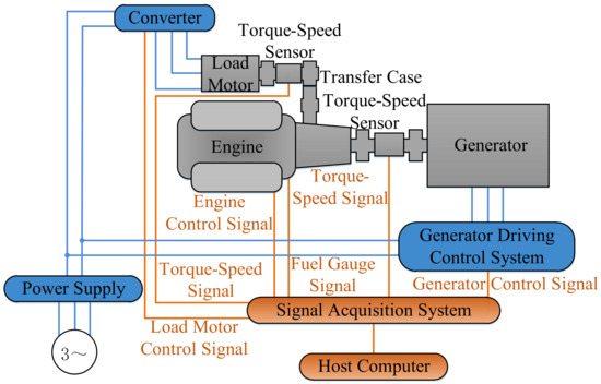
Figure 11.
Bench experiment of the mining truck’s powertrain.
In this platform, the engine-generator set is the same model as the one in the target vehicle XDE110 electric-drive mining truck of XCMG, as shown in Figure 12a. A 200 kW load motor is adopted to simulate the lifting pump’s load and hydraulic motor’s traction power. In order to realize the reversely drag control of the engine, our team developed the generator driving control system for electric-drive mining trucks, as shown in Figure 12b. For the sensor signal acquisition and control signal output in the experiment, the SCADAS signal acquisition system of LMS is adopted, as shown in Figure 12c.

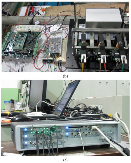
Figure 12.
The powertrain experimental platform of the electric-drive mining truck: (a) The overall powertrain experimental platform; (b) The generator driving control system; (c) The SCADAS signal acquisition system of LMS.
In the working cycle test of the electric-drive mining truck presented in the previous section, the DC bus voltage and current were measured and the electric braking and traction power was calculated. Therefore, to meet the requirements of the actual working conditions, the electric power in the bench experiment should be equal to the actual data shown in Figure 10.
In the downhill process, the engine is reversely dragged by the generator and the surplus mechanical power is recovered and converted into pressure energy by OHESS. While in the bench experiment, the actual electric braking power at the DC bus, as shown in Figure 10 after 1410 s, is the input power of the self-developed generator driving control system. Thus, the generator could reversely drag the engine, and the surplus mechanical power inputs into the load motor that simulates the lifting pump load through the transfer case. Meanwhile, the torque-speed sensor connected to the load motor measures the recovery power of OHESS and it is the exact input recovery power of the OHESS model for the following optimization study.
In the uphill process, the engine and OHESS jointly output mechanical power, which is then driving the wheel through the electric transmission system. Based on the following optimization study in the next sections, the output traction power of OHESS is obtained. Thus, in the bench experiment, the load motor controlled by the frequency converter outputs this traction power to simulate the hydraulic motor of OHESS. By this means, the fuel consumption and the corresponding CO2 emission under different optimization schemes are obtained through the fuel gauge.
Considering that the actual joint output power of the engine and OHESS (simulated by the load motor) in the bench experiment may not match the actual required electric traction power shown in Figure 10, closed-loop control is adopted based on the engine governor signal under the corresponding optimized EMS presented in the next sections.
4. Analysis of the Multi-Objective Optimization Problem
Based on the working cycle test of the mining truck and the bench experiment of its powertrain presented in Section 3, this section details the analysis of the multi-objective optimization problem of OHESS and obtains the global normalized optimization objective for further research.
4.1. Multi-Objective Optimization Problem
Energy density and system efficiency are the two main design objectives of OHESS. However, according to previous research [17], the two objectives are negatively correlated due to the heat effect of OHESS. Therefore, it is necessary to analyze the correlation between the two and select the appropriate weight factors to normalize them as a single objective for the subsequent structural optimization [30]. Meanwhile, considering that the mining trucks work with large environmental temperature differences, the impact of the seasonal temperature change on OHESS’s performance should be taken into account.
For the convenience of the following research, the storage volume per unit energy and the energy loss rate are adopted as the indicator of and , respectively, as shown in Equations (1) and (2):
Although the two objectives are expected to be as small as possible, they are negatively correlated. Thus, the appropriate weight factors (,) are needed to form a normalized objective shown in Equation (3).
The design space of OHESS includes three optimization variables, which are listed as follows:
where is the optimization vector, is the initial system pressure, is the number of accumulators, is the number of nitrogen tanks.
To make full use of the volume of OHESS and realize “fully charge” and “fully discharge”, the in is set from 11 MPa to 17 MPa, which corresponds to the upper limit of the compression ratio range (<2.45) of the containers with the maximum pressure of 42 MPa and a certain redundancy; To achieve the complete recovery of the downhill potential energy of mining trucks, the total internal volume of all accumulators is determined to be 1.7284 m3; as shown in Figure 6, with a certain total volume of accumulators, more accumulators mean smaller volume and weight of the hydraulic oil and the corresponding oil tank, which reduces the overall fuel consumption of the mining truck, thus the number of accumulators is selected from 8 to 14. According to the above total internal volume of all accumulators and the compression ratio range, the number of nitrogen tanks can be set from 4 to 8, as shown in Equation (5).
The main research steps in this section are as follows:
- Select a from the as the structural parameters;
- The optimal EMS of the OHESS with the selected structural parameters is obtained by using the Dynamic Programming (DP) algorithm;
- Based on the model of OHESS established in the previous work [17], taking the downhill recovery power measured in the bench experiment in Section 3.2 as the charging power, and the output traction power of the OHESS under the corresponding optimal EMS as the discharging power, the and of the OHESS are obtained.;
- After calculating each in , compare and analyze all the (, ) in Pareto solution set;
- Combining the ambient temperature comprehensive model, the global storage volume per unit energy and the global energy loss rate corresponding to different are obtained;
- Consider the influence of different ambient temperatures on the Pareto optimal solution, select the appropriate weight factors (,), and form the global normalized objective .
4.2. Energy Management Strategy
This section analyzes the EMS of the hybrid mining truck with OHESS and establishes the corresponding EMS optimization method based on the DP algorithm.
To reduce the fuel consumption and the corresponding CO2 emission of the hybrid mining truck, the energy of OHESS stored in the downhill process should be released when going uphill to provide part of the required traction power, so as to reduce the output power of the engine. Therefore, it is necessary to analyze the factors affecting the fuel consumption of the truck and determine the output power distribution strategy of the engine and OHESS in the uphill process.
Concerning the powertrain of the hybrid mining truck with OHESS, the main factors affecting the fuel consumption are the fuel consumption rate of the engine, the efficiency of the electric transmission system, and the system efficiency of OHESS.
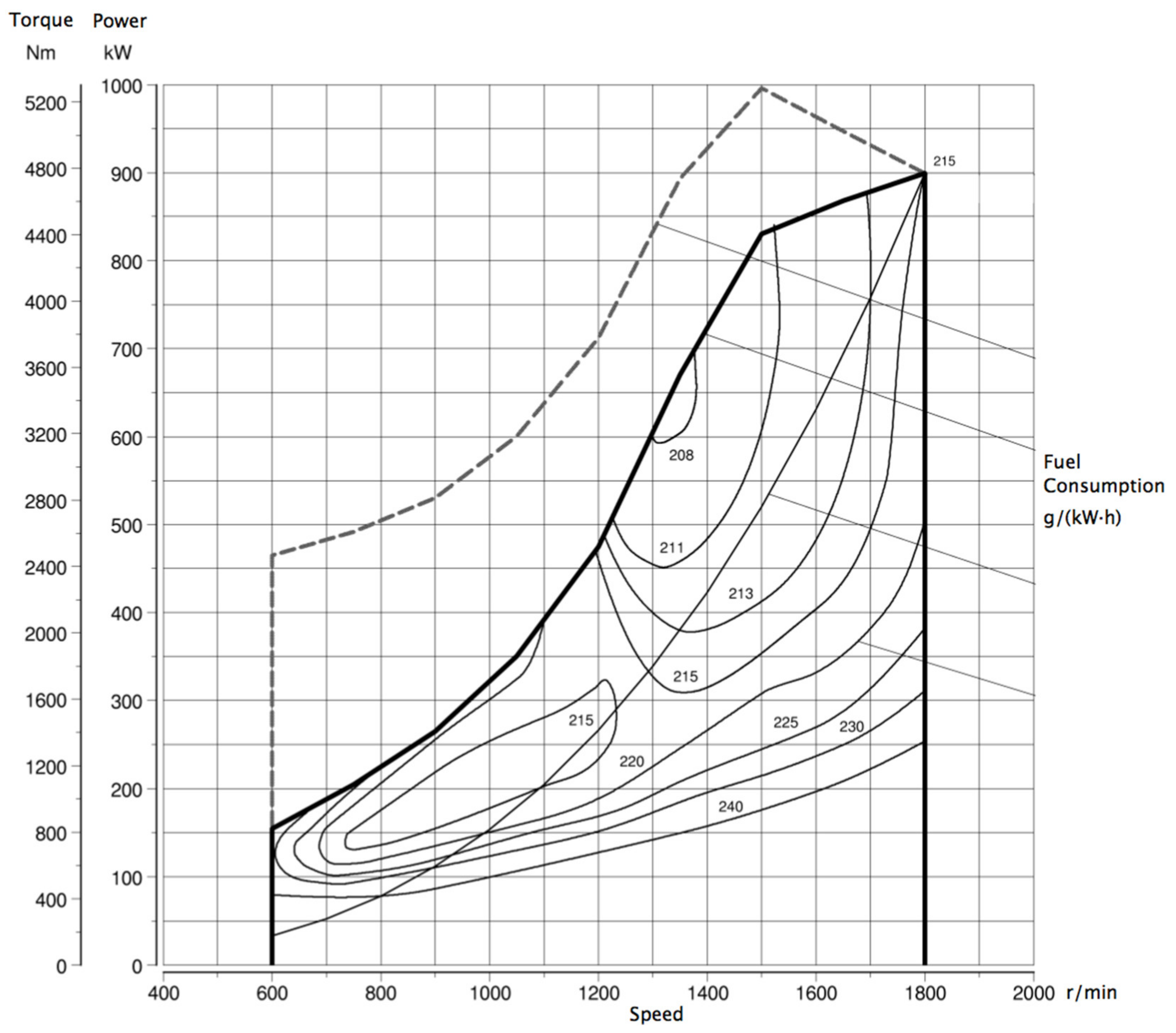
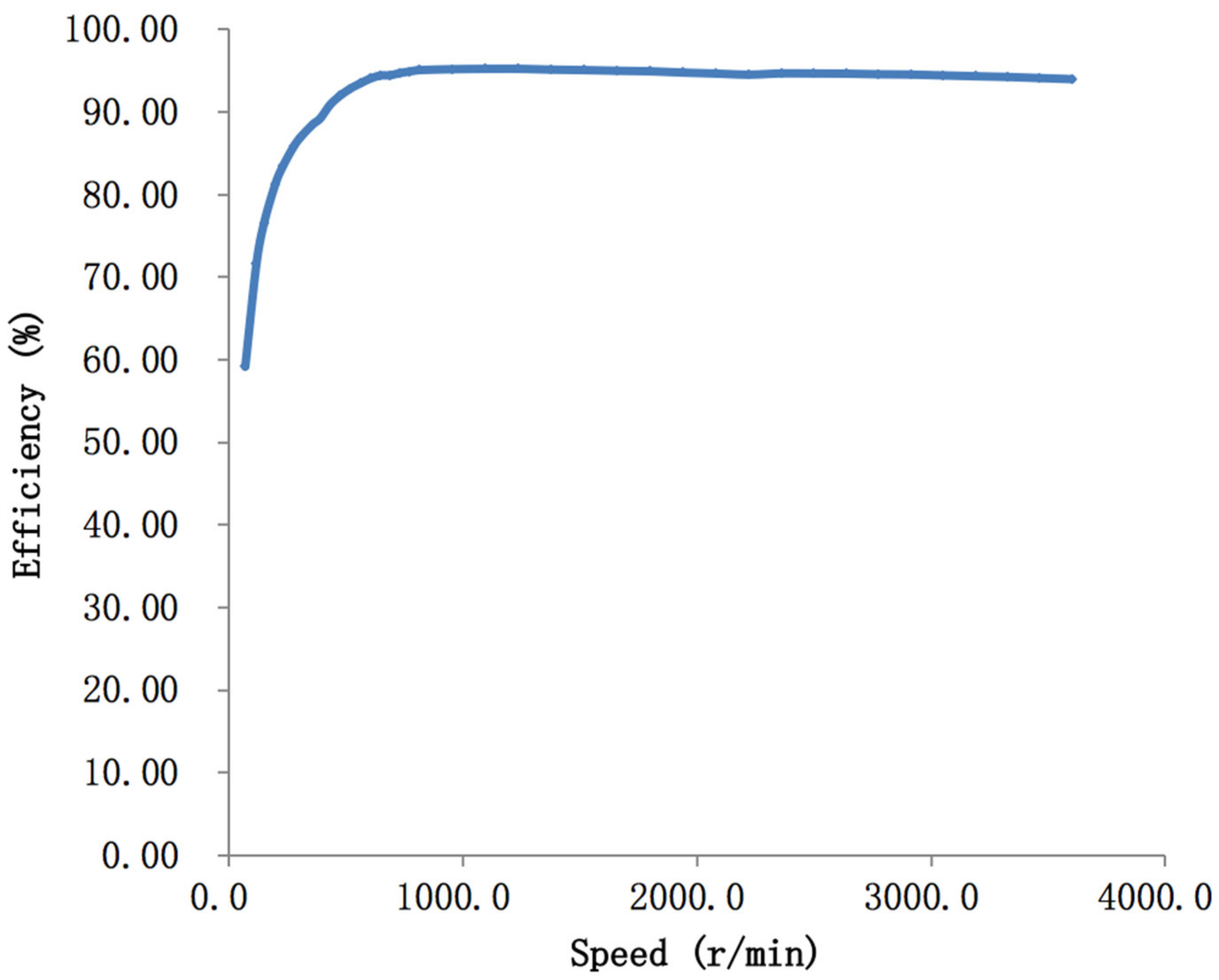
Based on the bench experiment in Section 3.2, the fuel consumption rate of the engine is obtained and shown in Figure 13. It shows that the engine has the highest efficiency at intermediate speed and load. Thus, the engine should work in the high-efficiency area, and avoid the low speed and load area, especially the idling area. Meanwhile, within the whole working area of the engine, it shall be controlled on the curve of the lowest fuel consumption rate. Considering that the engine and the generator are connected, the generator should also work in its high-efficiency area, whose driving efficiency curve is obtained by the bench test and shown in Figure 14.
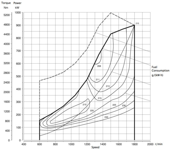
Figure 13.
Fuel consumption rate of the engine.

Figure 14.
Driving efficiency of the generator.
For the efficiency of the electric-drive system, besides the aforementioned generator efficiency, the efficiency of the rectifier, inverter and traction motor should also be considered. In the working cycle test of the mining truck presented in Section 3.1, the transfer efficiency of the electric power through the rectifier and inverter is measured and about 95%. Based on the bench experiment in Section 3.2, the efficiency of the traction motor is measured and shown in Figure 15.
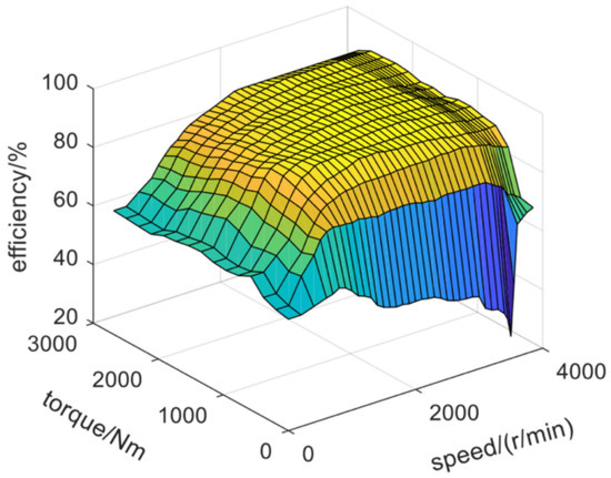
Figure 15.
Efficiency of the traction motor.
For the system efficiency of OHESS, it can only be described as a black-box system since there are many determinants and they are highly nonlinear. Therefore, based on the model of OHESS [17], the system efficiency can be obtained through simulation analysis under a certain and the corresponding optimal EMS. Moreover, to avoid heat accumulation after working cycles, which leads to overheating, the OHESS only outputs the traction power but does not accept the input engine power during the uphill process in the following study.
The DP is a discrete global optimization algorithm that is widely applied to solve the problem of EMS of hybrid vehicles. In terms of the design stage of the hybrid mining truck, we need to use this method to obtain the optimal solution for the OHESS optimization problem, and to evaluate the other results based on this benchmark. DP algorithm transforms a large optimization problem into a group of interrelated sub-problems of the same type, so it can use one certain decision-making method to solve the sub-problems more efficiently. The optimization results of the previously solved sub-problem are used to calculate the next sub-problem in turn. When the last sub-problem obtains the optimal solution, the one optimal solution of the whole problem is obtained. Its process is shown in Figure 16.

Figure 16.
Process of the DP algorithm.
Therefore, based on the above factor analysis, the DP algorithm is adopted to obtain the optimal EMS of the hybrid mining truck. The fuel consumption of hybrid mining truck is the optimization objective, which can be expressed in Equation (6); the required operation conditions of the powertrain are taken as constraints, namely the flow limit of lifting pump and hydraulic motor , the pressure limit of the accumulators and nitrogen tanks , the temperature limit of the hydraulic system , and the power limit of the cooling system , as shown in Equation (7); By superimposing the fuel consumption of each time step, the total fuel consumption in the whole working cycle period is obtained [31], in which the scheme with the minimum value is taken as the optimal EMS.
where is the required input or output power of the power assembly, is the engine output power or reverse dragging input power, is the input or output power of OHESS, is the temperature of pressured hydraulic oil, is the temperature of non-pressured hydraulic oil, is the temperature of pipeline oil, is the system pressure of OHESS, is the flow of lifting pump or hydraulic motor, is the cooling power.
Take the nitrogen volume of OHESS as the state variable of DP, and the flow of lifting pump and hydraulic motor as the decision variable. The relationship between them can be expressed in Equation (8) [32].
Based on the working cycle test data of rectifier efficiency and the generator efficiency shown in Figure 14, can be calculated by the demanded electric power on the DC bus in the uphill process shown in Figure 10 and can be obtained by the OHESS model [17] and the decision variable of DP, thus shall be calculated by Equation (7). Then, according to the engine fuel consumption rate shown in Figure 13, the of the power assembly can be obtained. The parameters of the DP algorithm are shown in Table 2.
Table 2.
Parameters of the DP algorithm.
4.3. Pareto Optimal Solution
Based on the above analysis, this section compares and analyzes the and corresponding to different in Pareto solution set.
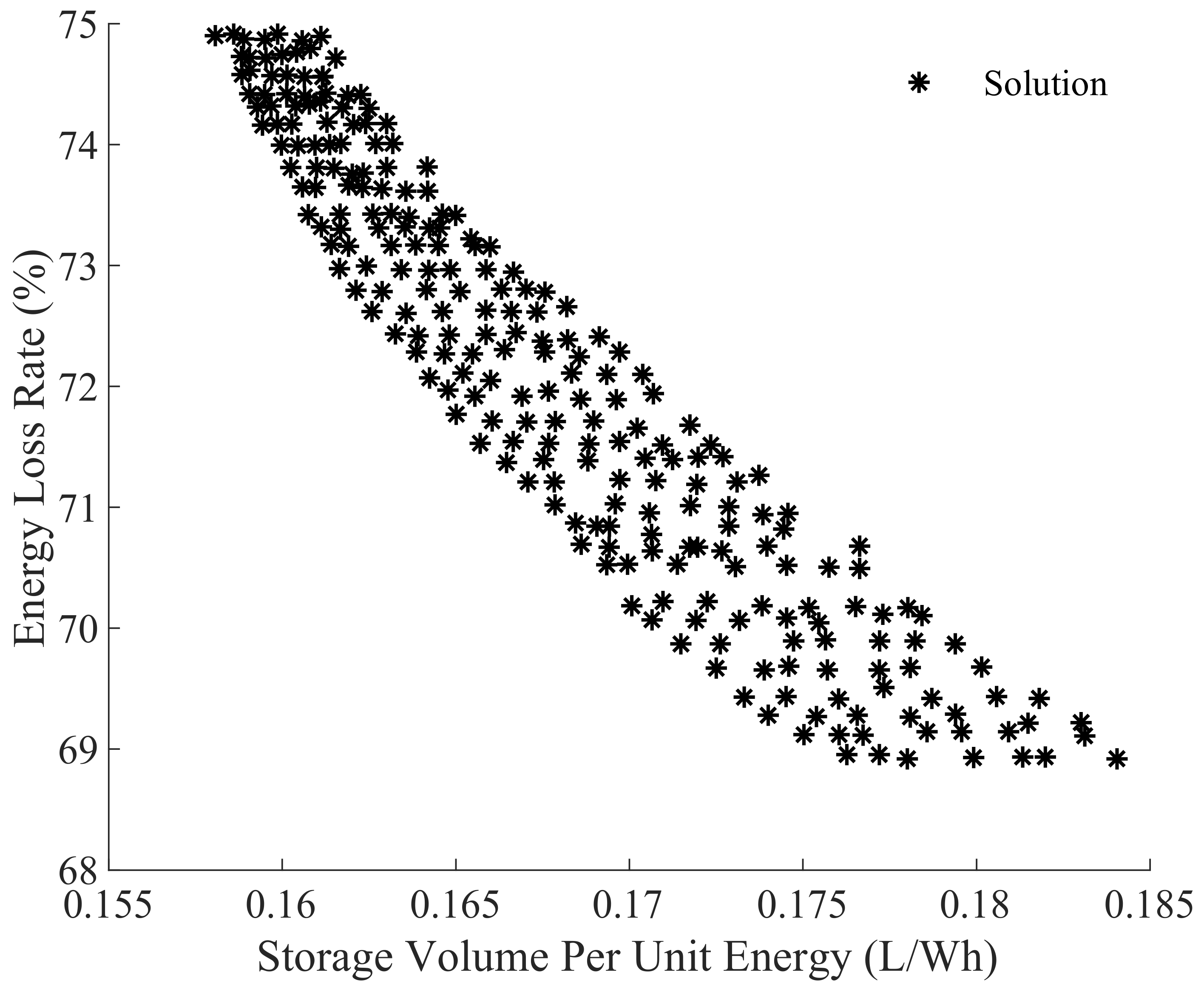
There are 245 in the design space . Each needs to go through the simulating calculation of the DP and OHESS model. After calculating all the , draw each (, ) together, as shown in Figure 17. It shows the relationship between energy density and system efficiency of OHESS.

Figure 17.
Scheme results of OHESS.
Figure 17 shows that the and are two contradictory objectives. When one reaches the ideal value, the other will deteriorate, that is, the is inversely proportional to the of OHESS. The reason is that mainly depends on the number of accumulators . As shown in Figure 6, more accumulators mean a smaller volume and weight of the hydraulic oil and the corresponding oil tank, which reduces the overall fuel consumption of the hybrid mining truck. However, according to previous research [17], increasing will degrade the thermal process and reduce the due to the heat effect of OHESS. Besides, although more nitrogen tanks will reduce , it will avoid system overheating and improve the . In all the 245 schemes in , ranges from 0.1577 L/Wh to 0.1840 L/Wh, and ranges from 68.92% to 74.91%.
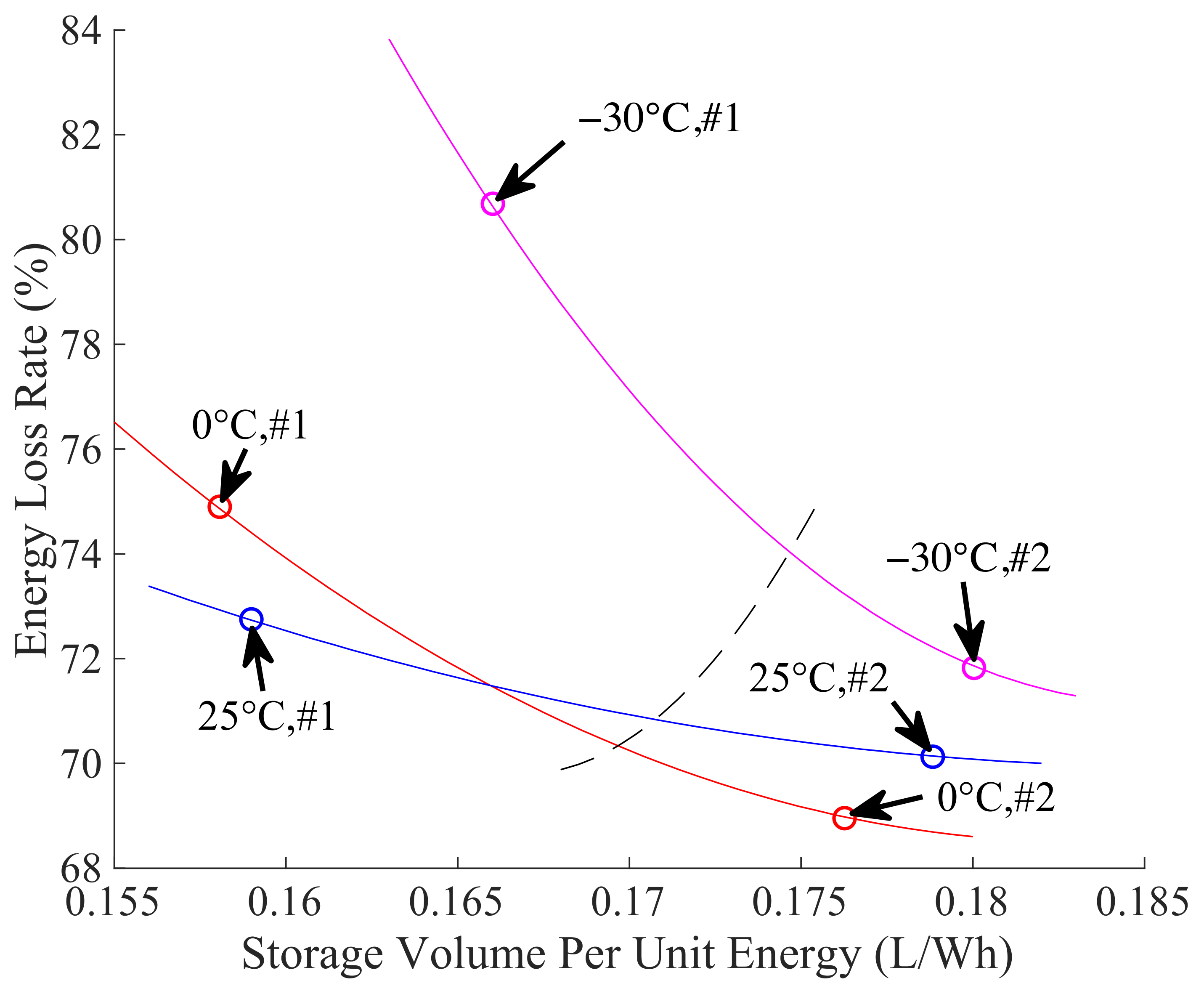
From the 245 schemes shown in Figure 17, 35 schemes close to the minimum values of and at the same time are selected to form the Pareto front, as shown in Figure 18. To choose the optimal solution from the Pareto front, two schemes are selected: #1 with the smallest ; And #2 with the smallest . Table 3 lists the optimization variables, objectives, and other main parameters corresponding to the two schemes, where of the two schemes are the same and #1 has more accumulators, lesser nitrogen tanks, smaller system volume and weight , and lower . Whereas #2 has lesser accumulators, moderate nitrogen tanks, larger and , and higher .
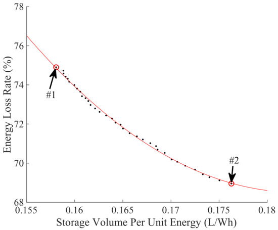
Figure 18.
Pareto optimal solution at 0 °C.
Table 3.
Two schemes on the Pareto front.
Since and of the actual OHESS is between #1 and #2, the appropriate weight factors (,) should be selected to normalize the two objectives. Considering that the ambient temperature significantly affects and of OHESS [17], it should also be taken into account.
4.4. Ambient Temperature Comprehensive Model
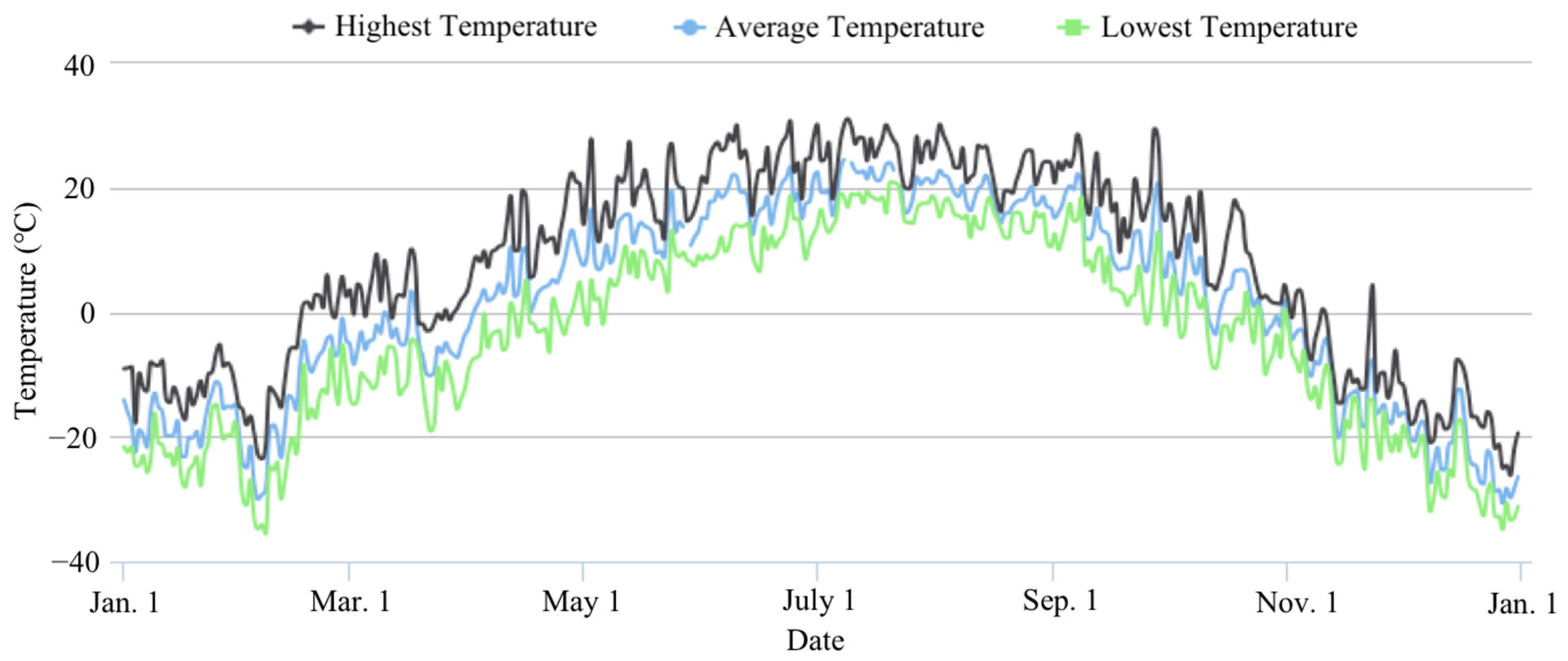
In practical application, the performance of OHESS will be affected by ambient temperature. It is because the density of high-pressure nitrogen with the same pressure has a distinct density in different temperatures, thus having various stored pressure energy. An optimal parameter scheme in one temperature may not be optimal in another. For open-pit mines in high latitudes, the seasonal temperatures vary greatly. However, the mining trucks need to work continuously for 365 days in the open-air environment. Therefore, the influence of the ambient temperature on the performance of OHESS should be considered. The ambient temperature comprehensive model is established in this section.
An open-pit mine in Heihe, China with a large seasonal temperature difference is selected as the application environment, whose temperature is shown in Figure 19 [33]. Due to the massive data of the daily average temperatures throughout the year, it is divided into six intervals to simplify the optimization calculation, that is, below −25 °C, from −25 °C to −15 °C, from −15 °C to −5 °C, from −5 °C to 5 °C, from 5 °C to 15 °C, and from 15 °C to 25 °C. The numbers of the actual temperatures that fall in each interval are recorded as the ambient temperature weight , namely, , , , , , and . Therefore, the global storage volume per unit energy and the energy loss rate can be calculated by Equations (9) and (10).
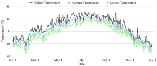
Figure 19.
Annual ambient temperature of Heihe, China in 2019 [33].
4.5. Transformed Single-Objective Optimization
Based on the above analysis, this section analyzes the two contradictory objectives, selects the appropriate weight factors, and obtains the global normalized optimization objective.
Figure 19 shows that the seasonal ambient temperature varies greatly for mining trucks. The maximum daily average temperature in summer is about 25 °C, while the minimum one in winter can even reach −30 °C. To more comprehensively analyze the OHESS performance in the annual working cycle of hybrid mining trucks, and hence obtain the appropriate multi-objective normalized weight factors, the Pareto fronts at −30 °C and 25 °C are compared with it at 0 °C, as shown in Figure 20.
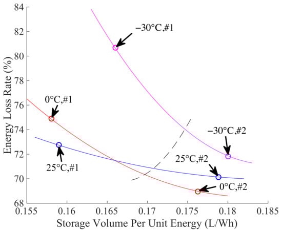
Figure 20.
Pareto optimal solutions at different temperatures.
It can be seen that when the ambient temperature is 0 °C, scheme #1 with the minimum , and #2 with the minimum , both have smaller than those at −30 °C and 25 °C. This is because the is calibrated at 0 °C. Whereas the nitrogen at −30 °C has the same number of moles, which leads to a lower . This does not match the optimal volume of accumulator and nitrogen tanks, hence affecting the . The situation is similar when the ambient temperature is 25 °C. Due to the fact that the OHESS with a selected scheme will work throughout the year, choose the calibrated at 0 °C could increase the .
Since the at −30 °C is significantly higher than that at 0 °C and 25 °C, which affects the overall fuel consumption of hybrid mining trucks, it should be ensured that the selected scheme has a reasonable under low temperatures. Therefore, the weight factor corresponding to is selected as 0.641, corresponding to is selected as 0.359. The scheme of the normalized objective at different temperatures is shown in the intersection of the black dotted line and Pareto fronts in Figure 20. Combining with the ambient temperature comprehensive model established in Section 4.4, the global normalized optimization objective , which is calculated by Equations (3), (9) and (10), can be expressed as:
Since there are only 245 finite discrete schemes in , which do not include the one corresponding to . Thus, the one in , which is the closest to the scheme corresponding to , is selected as the multi-objective comprehensive scheme, whose is 13 MPa, is 12, is 6, is 5.8173 Wh/L, is 27.09%.
Based on the bench experiment described in Section 3.2, for the hybrid mining truck with OHESS in this scheme, the reduced fuel consumption and CO2 emission are 21.93 kg/day and 67.11 kg/day, respectively.
5. Nested Optimization of the Energy Storage System
Based on the global normalized optimization objective presented in Section 4, this section obtains the optimal structure of OHESS under the corresponding optimal EMS through nested optimization based on global optimization algorithms.
5.1. Nested Optimization Method
This section establishes a nested optimization method and solves the problem of the OHESS structure and EMS optimization.
Consider the influence of the accumulator’s volume and nitrogen tank’s volume on , the volume correction coefficients of accumulators and nitrogen tanks, that is, and , are introduced as the optimization variables. They are both range from 0.5 to 1.5, and satisfied:
where is the corrected volume of the accumulator, is the original mass of accumulator, is the corrected mass of accumulator, is the corrected volume of nitrogen tank, is the original mass of nitrogen tank, is the corrected mass of the nitrogen tank.
The is transformed from discrete variable to continuous one, hence a continuous design space is formed, as shown in Equation (16).
The inner layer of nested optimization takes the fuel consumption of hybrid mining trucks as the optimization objective and obtains the optimal EMS through the DP algorithm. The solution process is the same as that in Section 4.2. After each optimal EMS corresponding to a scheme in is solved by DP, the power of OHESS and engine in the working cycle can be calculated, thus the can be obtained.
The outer layer of nested optimization takes the global normalized objective as the optimization objective and obtains the optimal structural scheme by the global optimization algorithm. Considering that in the process of global optimization search, each selected in needs to call the time-consuming DP algorithm, the global optimization algorithm should have efficient search ability to solve this kind of complex black-box problem.
Figure 21 is the nested optimization flow chart, and the main steps are as follows:
- Based on the global optimization algorithms, a are selected from the as the input to DP algorithm;
- The DP algorithm is used to obtain the optimal EMS, which is the working condition of OHESS;
- Combine the simulation results of the OHESS and the ambient temperature comprehensive model to calculate ;
- If the current solution satisfies the constraints, compare and update the optimal solution, and then terminate the calculation when the stop criteria are met; otherwise, repeat steps 1 to 3.
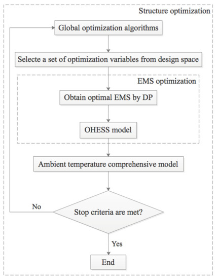
Figure 21.
Flow chart of the nested optimization.
Figure 21.
Flow chart of the nested optimization.
5.2. Global Optimization Algorithms
To solve this complex nonlinear hybrid optimization problem, two global optimization algorithms, GA and AMGO, are introduced in this section.
5.2.1. Genetic Algorithm
GA is a classical optimization algorithm. It simulates the evolution of an artificial population with individuals containing genes (optimization variables) through the selection, crossover, and mutation process [34]. Finally, the genes of the optimal individual in the last generation are decoded to obtain the optimal solution to the optimization problem [35].
Figure 22 is the GA flow chart, and the main steps are as follows:
- Initialize the population;
- Evaluate the fitness of individuals in the population;
- Select the reserved individuals by their fitness ranking, and eliminate the rest;
- Generate the next generation by crossover and mutation operations on the reserved individuals;
- Repeat steps 2 to 4 until the stop criteria are met.
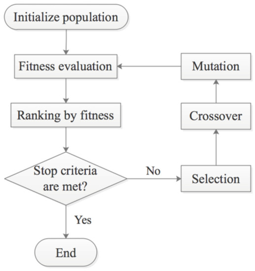
Figure 22.
Flow chart of GA.
Figure 22.
Flow chart of GA.
5.2.2. Adaptive Metamodel-Based Global Optimization
As an efficient Metamodel-based algorithm, AMGO is very effective for solving the highly nonlinear hybrid optimization problem of OHESS. It adopts a hybrid Metamodel of kriging and augmented radial basis function, and the adaptive weight factors of the two. A sub-optimization problem is constructed during iterations to balance the local and global search [36].
Figure 23 is the AMGO algorithm flow chart, and the main steps are as follows:
- Generate the initial sample points by Latin hypercube sampling method;
- Calculate the function value of each sample point and update the sample set;
- Initialize the approximate optimal point and the corresponding value;
- Construct the hybrid Metamodel according to the sample set;
- Obtain the next sampling point by solving an optimization subproblem;
- Calculate the actual function value of the next sampling point, and determine whether to update the current optimal value by comparing them;
- Evaluate the errors of the two Metamodels at the next sampling point, and then determine the weight factors of the hybrid Metamodels in the next iteration;
- Update the sample set;
- Repeat steps 4 to 8 until the stop criteria are met.
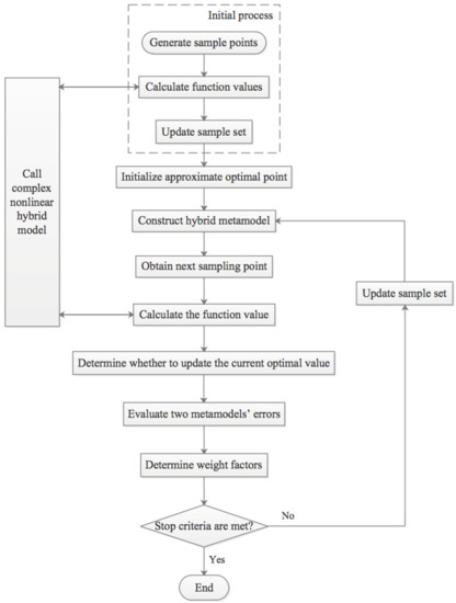
Figure 23.
Flow chart of AMGO.
Figure 23.
Flow chart of AMGO.
5.3. Optimization Results
To solve the complex black-box problem of the nested optimization of OHESS, this section adopts GA and AMGO algorithms to search for the global optimal solution.
Since nested optimization is very time-consuming, it takes about 38 min for each function evaluation. Therefore, the NFE that reflects the total computation cost is the key indicator to evaluate the selected global optimization algorithms [37].
The optimization calculation is carried out on a workstation with a dual CPU of Intel Xeon silver 4208 (2.10 GHz) and 96 GB RAM. For the parameters of GA, the population size is set as 10, the genetic algebra is limited to 40. The crossover rate and mutation rate are set as 1.0 and 0.01, respectively. After 224.19 h of calculation, the best result of 0.5235 is obtained within 40 generations, as shown in Figure 24. The corresponding scheme is , , , , .
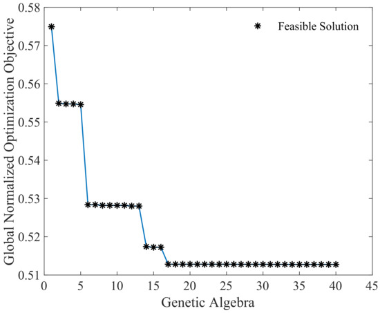
Figure 24.
Iterative results of GA.
With the same optimization objective, constraints, and variables, the iterative process of the AMGO algorithm is shown in Figure 25. The first 25 points are training samples, and the number of iterations is set to 100. After 65.37 h of calculation, the optimal solution appears on the 52nd function call, the objective value is 0.5128, and the corresponding optimal scheme is , , , , . It can be seen that after the 25 initial training sample points, the infeasible solutions become less and less. Meanwhile, with the increase of NFE, the AMGO algorithm can quickly find the optimal region and update the optimal solution set until the stop criteria are met.
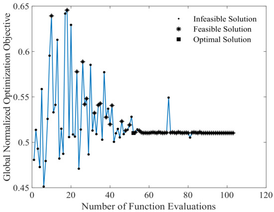
Figure 25.
Iterative results of AMGO.
To comprehensively compare the performance of GA and AMGO algorithms, the solution results of the two are compared in Table 4. The optimal solution obtained by the AMGO algorithm is 2.1% lower than that of GA. The AMGO’s calculation time and NFE are only 29.16% and 25.75% of GAs. This is attributed to AMGO’s advantage of using Metamodel, which significantly reduces the computation cost of complex black-box optimization problems [38]. Although GA can get the feasible solution after 224.19 h of calculation, it needs more iterations to achieve the optimal solution. While the AMGO algorithm based on an adaptive hybrid Metamodel reduces the NFE requirement, thus converges to the optimal solution within 66 h.
Table 4.
Solution results of GA and AMGO.
5.4. Comparison Considering Different Annual Temperatures
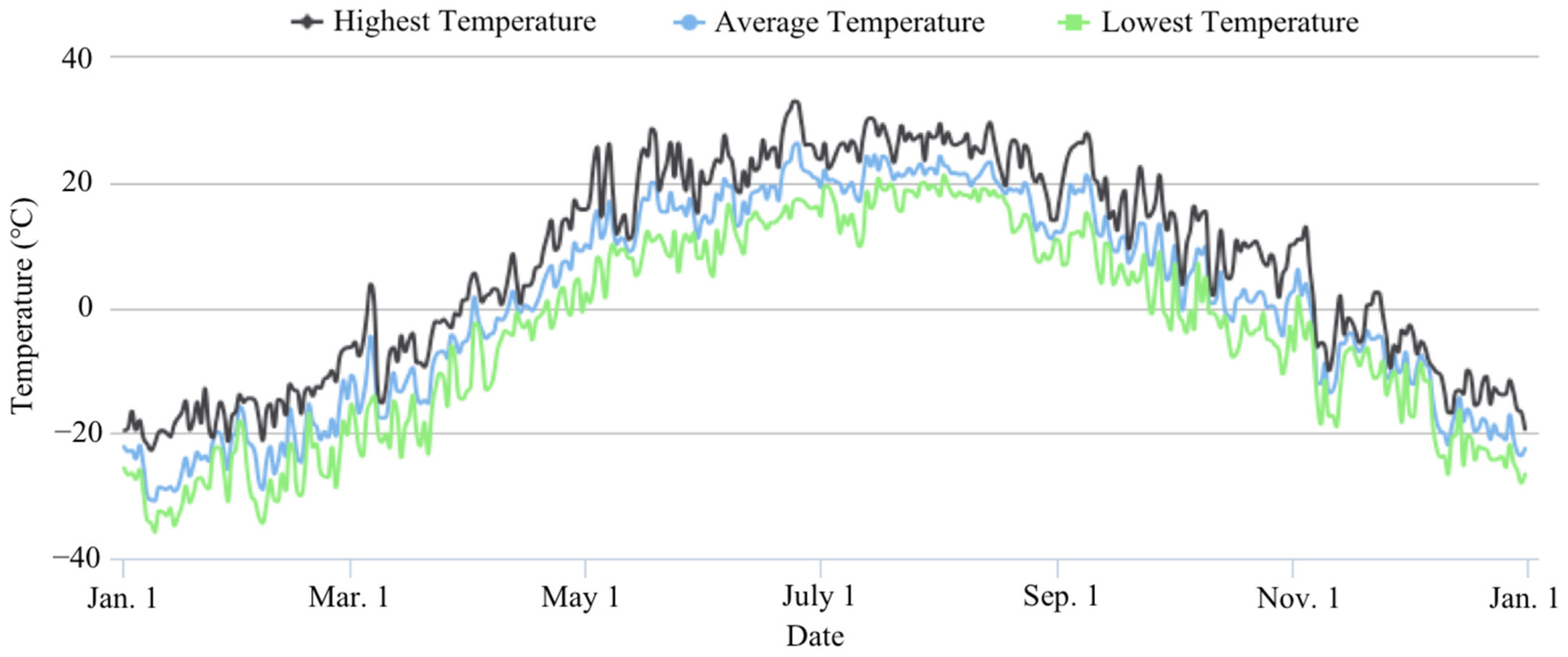
Considering that the service life of mining trucks is about 10 years, the ambient temperatures are different every year, which has a significant impact on OHESS performance. Therefore, this section continues to use the AMGO algorithm but adopts ambient temperatures in 2013 (colder) and 2017 (hotter), as shown in Figure 26 and Figure 27.
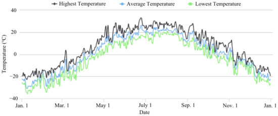
Figure 26.
Annual ambient temperature of Heihe, China in 2013 [33].
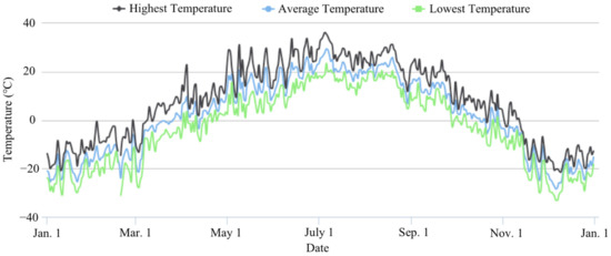
Figure 27.
Annual ambient temperature of Heihe, China in 2017 [33].
With the ambient temperatures in colder 2013, the optimal solution of AMGO is 0.5149. The corresponding optimal scheme is , , , , . While for the hotter 2017, the optimal solution is 0.5121. The corresponding optimal scheme is , , , , . To analyze the differences of the optimal schemes under three different annual ambient temperatures, the relevant results are listed in Table 5.
Table 5.
Solution results of AMGO in different years.
The optimal scheme of OHESS in hotter 2017 has a lower system volume , weight , fuel consumption, and global normalization objectives. It has a smaller and accumulator volume but a larger nitrogen tank volume. While in the older 2013, the results are opposite. This is because the calibrated at 0 °C has higher pressure potential at higher ambient temperature.
In summary, similar to the situation under different seasonal temperatures, different annual temperatures will also affect the optimal solution of OHESS.
5.5. Comparison with Multi-Objective Comprehensive Scheme
In the previous multi-objective optimization analysis, the multi-objective comprehensive scheme is , , . This section compares it with the optimal scheme of the nested optimization.
To make full use of the volume of OHESS, it should realize “fully charge” and “fully discharge”. That means the total volume of the accumulators should be as close as possible to the volume change of nitrogen in the energy recovery process, so that the former can be fully utilized, and further reduce the redundant volume. It can lower the weight of the accumulators and the volume of circulating hydraulic oil, so as to cut down the additional vehicle load of OHESS, thus reducing the fuel consumption and CO2 emission of the hybrid mining truck.
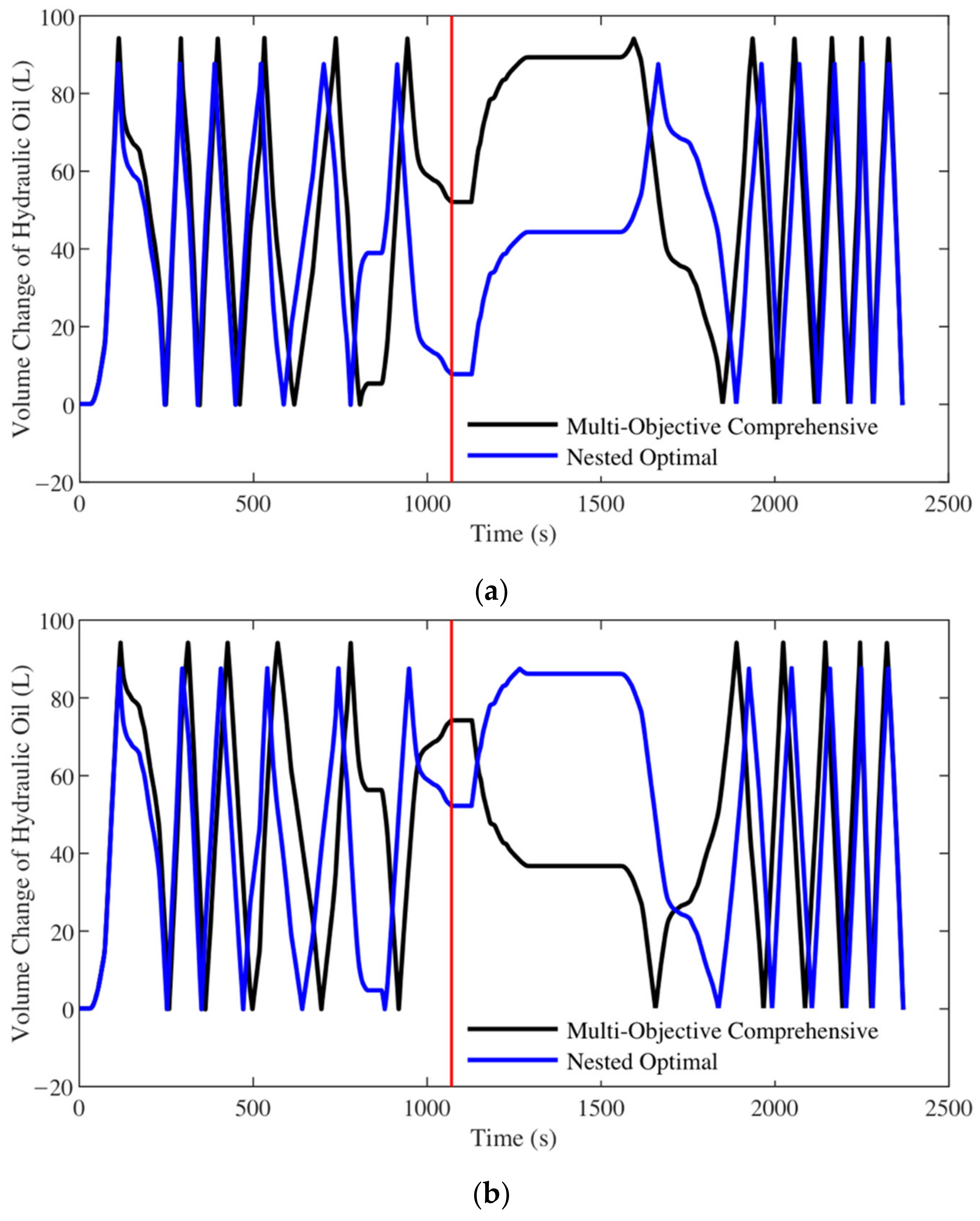
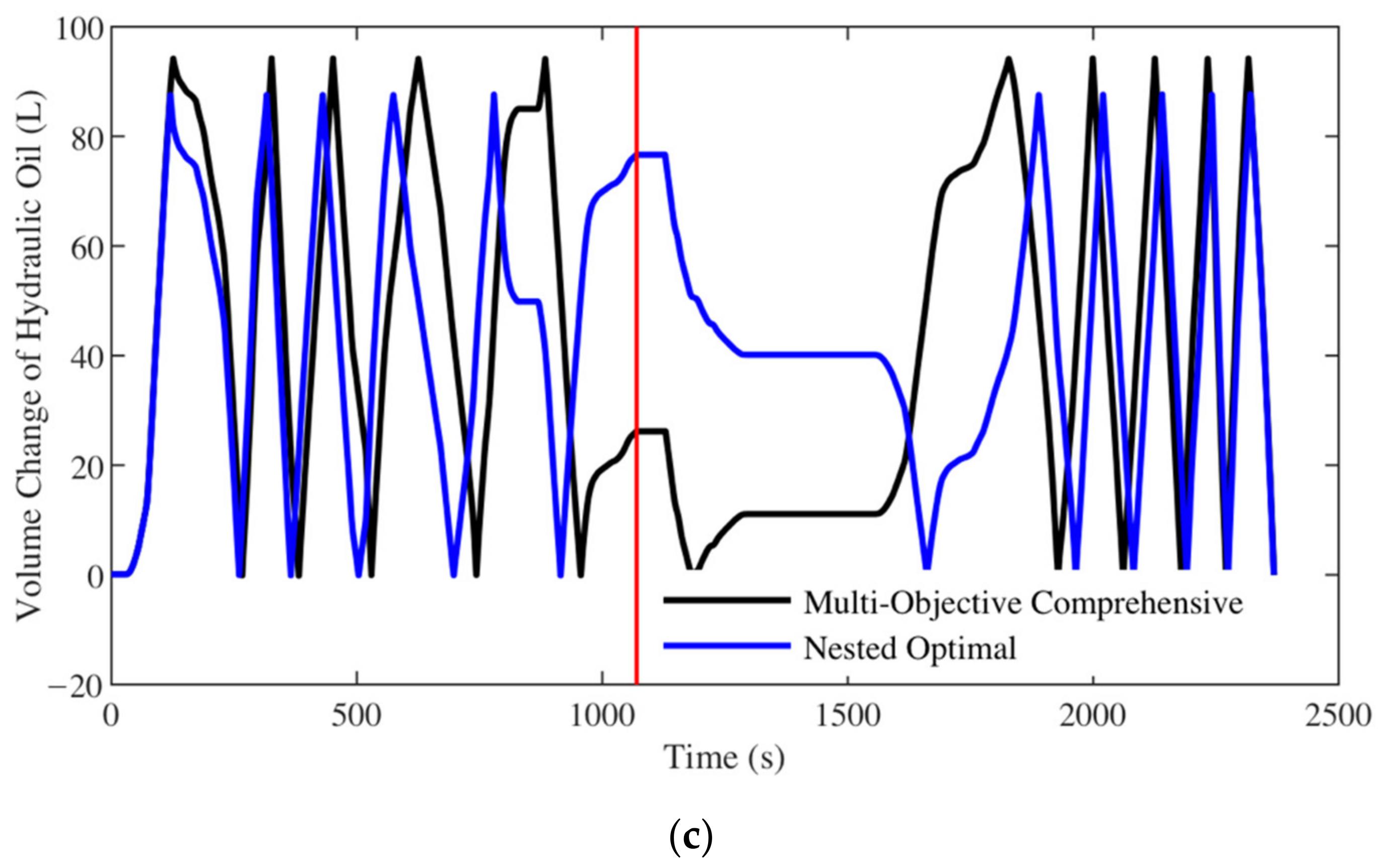
Because the multi-objective comprehensive scheme is based on a finite solution set, it does not take infinite continuous variables of and into account. Considering that the numbers of the accumulators in the multi-objective comprehensive scheme and the nested optimal scheme are both 12, to achieve “fully charge” and “fully discharge”, the volume of hydraulic oil in the odd-number functioning accumulator should complete 6 full-empty cycles just before the end of the process, that is, there should be six complete waveforms before the red line in Figure 28. Define the volume utilization rate as 100% when the system achieves “fully charge” and “fully discharge”. In this case, the volume of hydraulic oil in the odd-number functioning accumulator should be reduced to 0 at the red line in Figure 28 after 6 waveforms. For a case that it is not 0 at the red line, the ratio of the volume of compressed nitrogen to the total volume of the accumulators is the volume utilization rate.
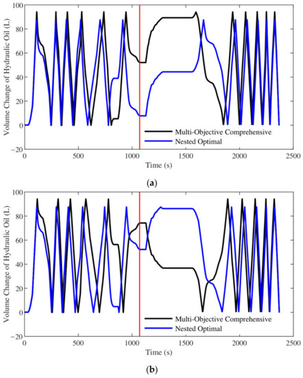

Figure 28.
Volume change of hydraulic oil at different temperatures: (a) −30 °C; (b) 0 °C; (c) 25 °C.
In Figure 28a, there are almost six completed waveforms before the red line for the optimal scheme of the nested optimization at −30 °C. The corresponding volume utilization rate reaches 99.27%, while the one for the multi-objective comprehensive scheme is only 95.40%. Comparing Figure 28a–c, it can be found that although the volume utilization rate decreases with the increase of the ambient temperature, the nested optimal scheme still has a 90.63% one at the highest temperature. The relevant results are listed in Table 6.
Table 6.
Multi-objective comprehensive scheme and nested optimal scheme.
As shown in Table 6, compared with the multi-objective comprehensive scheme, the nested optimal scheme has a lower optimization result, smaller volume and weight , and lesser fuel consumption and CO2 emission. Moreover, the nested optimal scheme also has a higher volume utilization rate under different ambient temperatures. Therefore, taking and into account and using the advanced AMGO algorithm to solve the complex nonlinear hybrid optimization problem of OHESS, can obtain better optimization results with a lower computation cost.
6. Conclusions
In order to recover and utilize the potential energy of mining trucks efficiently, this paper proposes a nested optimization method of its novel energy storage system. By analyzing the multi-objective optimization problem of the oil-circulating hydro-pneumatic energy storage system, a nested optimization method based on the advanced adaptive Metamodel-based global optimization algorithm is carried out. With the data from the working cycle test and bench experiment of the mining truck, the optimization research shows that this nested method only requires a short time to solve the complex optimization problem, and achieves better results. The optimized scheme has higher system efficiency, energy density, and volume utilization rate, thus obtaining a smaller system volume and weight. Verified by the bench experiment of its powertrain, the hydro-pneumatic hybrid mining truck with the optimized scheme reduces its fuel consumption and CO2 emission by 23.57 kg/day and 72.12 kg/day compared with the reverse dragging one, respectively. Considering the idling fuel consumption of regular mining trucks in the downhill process is 189.84 kg/day, the total fuel saving and CO2 emission reduction are 213.42 kg/day and 652.83 kg/day, respectively.
The above conclusions carry out a feasible solution to the complex nonlinear hybrid optimization problem of the oil-circulating hydro-pneumatic energy storage system. Therefore, it lays the foundation for the practical application of hydro-pneumatic hybrid mining trucks.
Author Contributions
Conceptualization, J.H. and C.J.; methodology, T.Y.; software, Y.L.; validation, J.H., T.Y. and Y.L.; formal analysis, C.J.; investigation, T.Y.; resources, J.H.; data curation, T.Y.; writing-original draft, T.Y.; visualization, J.H.; supervision, T.Y.; project administration, C.J.; funding acquisition, J.H. and L.G.; writing—review & editing, L.G. All authors have read and agreed to the published version of the manuscript.
Funding
This research was funded by Ministry of Science and Technology of the People’s Republic of China, grant number 2016YFC0802905, and Shunde Graduate School of University of Science and Technology Beijing, grant number BK19BE003.
Institutional Review Board Statement
Not applicable.
Informed Consent Statement
Not applicable.
Data Availability Statement
The original contributions presented in the study are included in the article; further inquiries can be directed to the corresponding author.
Acknowledgments
The authors, therefore, acknowledge and thank Ministry of Science and Technology of the People’s Republic of China and Shunde Graduate School of University of Science and Technology Beijing, for their technical and financial support.
Conflicts of Interest
The authors declare no conflict of interest. The funders had no role in the design of the study; in the collection, analyses, or interpretation of data; in the writing of the manuscript, or in the decision to publish the results.
References
- Gu, Z.; Mi, C.; Ding, Z.; Zhang, Y.; Liu, S.; Nie, D. An energy-based fatigue life prediction of a mining truck welded frame. J. Mech. Sci. Technol. 2016, 30, 3615–3624. [Google Scholar] [CrossRef]
- Yang, W.W. Investigation of Control Strategy of an Innovational Hybrid Electric Transmission System for Off-Road Trucks. Ph.D. Thesis, University of Science and Technology Beijing, Beijing, China, 2020. [Google Scholar]
- Koellner, W.; Brown, G.; Rodriguez, J.; Pontt, J.; Cortes, P.; Miranda, H. Recent Advances in Mining Haul Trucks. IEEE Trans. Ind. Electron. 2004, 51, 321–329. [Google Scholar] [CrossRef]
- Sahoo, L.K.; Bandyopadhyay, S.; Banerjee, R. Benchmarking energy consumption for dump trucks in mines. Appl. Energy 2014, 113, 1382–1396. [Google Scholar] [CrossRef] [Green Version]
- Yamakawa, J.; Kojima, A.; Watanabe, K. A method of torque control for independent wheel drive vehicles on rough terrain. J. Terramechanics 2007, 44, 371–381. [Google Scholar] [CrossRef]
- Tseng, K.-J.; Chen, G. Computer-aided design and analysis of direct-driven wheel motor drive. IEEE Trans. Power Electron. 1997, 12, 517–527. [Google Scholar] [CrossRef]
- Esfahanian, E.; Meech, J.A. Hybrid Electric Haulage Trucks for Open Pit Mining. In Proceedings of the 16th IFAC Symposium on Control, Optimization and Automation in Mining, Minerals and Metal Processing, San Diego, CA, USA, 25–28 August 2013; Volume 46, pp. 104–109. [Google Scholar]
- Richter, T.; Slezak, L.; Johnson, C.; Young, H.; Funcannon, D. Advanced Hybrid Propulsion and Energy Management System for High Efficiency, Off Highway, 240 Ton Class, Diesel Electric Haul Trucks. In Annual Progress Report for Heavy Vehicle Systems Optimization Program, Washington; GE Global Research: Niskayuna, NY, USA, 2007. [Google Scholar]
- Hong, J.; Wang, Z.; Chen, W.; Wang, L.; Lin, P.; Qu, C. Online accurate state of health estimation for battery systems on real-world electric vehicles with variable driving conditions considered. J. Clean. Prod. 2021, 294, 125814. [Google Scholar] [CrossRef]
- Mi, C.; Gu, Z.; Yang, Q.; Nie, D. Frame fatigue life assessment of a mining dump truck based on finite element method and multibody dynamic analysis. Eng. Fail. Anal. 2012, 23, 18–26. [Google Scholar] [CrossRef]
- Hong, J.; Wang, Z.; Ma, F.; Yang, J.; Xu, X.; Qu, C.; Zhang, J.; Shan, T.; Hou, Y.; Zhou, Y. Thermal Runaway Prognosis of Battery Systems Using the Modified Multi-Scale Entropy in Real-World Electric Vehicles. IEEE Trans. Transp. Electr. 2021, 7, 2269–2278. [Google Scholar] [CrossRef]
- Zaman, M.S.U.; Haider, R.; Bukhari, S.B.A.; Ashraf, H.M.; Kim, C.-H. Impacts of Responsive Loads and Energy Storage System on Frequency Response of a Multi-Machine Power System. Machines 2019, 7, 34. [Google Scholar] [CrossRef] [Green Version]
- Hong, J.; Wang, Z.; Yao, Y. Fault prognosis of battery system based on accurate voltage abnormity prognosis using long short-term memory neural networks. Appl. Energy 2019, 251, 113381. [Google Scholar] [CrossRef]
- Datasheet of XDE110. Available online: http://www.xcmg.com/ (accessed on 17 August 2019).
- Jin, C.; Yi, T.; Shen, Y.; Khajepour, A.; Meng, Q. Comparative study on the economy of hybrid mining trucks for open-pit mining. IET Intell. Transp. Syst. 2019, 13, 201–208. [Google Scholar] [CrossRef]
- Yi, T.; Ma, F.; Jin, C.; Huang, Y. A novel coupled hydro-pneumatic energy storage system for hybrid mining trucks. Energy 2018, 143, 704–718. [Google Scholar] [CrossRef]
- Yi, T.; Ma, F.; Jin, C.; Hong, J.; Liu, Y. Investigation on Thermal Characteristics of the Oil-Circulating Hydraulic Energy Storage System for Hybrid Mining Trucks. Front. Energy Res. 2021, 9, 733919. [Google Scholar] [CrossRef]
- Liu, J.J. Optimal Design and Control of Li-Battery/Ultracapacitor Hybrid Energy Storage System. Ph.D. Thesis, University of Science and Technology Beijing, Beijing, China, 2018. [Google Scholar]
- Song, Z.; Li, J.; Han, X.; Xu, L.; Lu, L.; Ouyang, M.; Hofmann, H. Multi-objective optimization of a semi-active battery/supercapacitor energy storage system for electric vehicles. Appl. Energy 2014, 135, 212–224. [Google Scholar] [CrossRef]
- Hung, Y.-H.; Wu, C.-H. An integrated optimization approach for a hybrid energy system in electric vehicles. Appl. Energy 2012, 98, 479–490. [Google Scholar] [CrossRef]
- Lu, K.; Phung, T.H.; Sultan, I.A. On the Design of a Class of Rotary Compressors Using Bayesian Optimization. Machines 2021, 9, 219. [Google Scholar] [CrossRef]
- Xu, P.P.; Cai, T.F.; Yi, Y.; Pan, Y. The Frequency Feature Extraction of the Signal in Oscillation Cavity of a Self-Resonating Jet Nozzle Based on Improved HHT Method. Chin. J. Eng. 2015, 12, 99–105. [Google Scholar]
- Liu, Q.; Zha, Y.; Liu, T.; Lu, C. Research on Adaptive Control of Air-Borne Bolting Rigs Based on Genetic Algorithm Optimization. Machines 2021, 9, 240. [Google Scholar] [CrossRef]
- Jiang, R.; Ci, S.; Liu, D.; Cheng, X.; Pan, Z. A Hybrid Multi-Objective Optimization Method Based on NSGA-II Algorithm and Entropy Weighted TOPSIS for Lightweight Design of Dump Truck Carriage. Machines 2021, 9, 156. [Google Scholar] [CrossRef]
- Zhou, X.J.; Ma, Y.Z.; Li, X.F. Ensemble of surrogates with recursive arithmetic average. Struct. Multidiscip. Optim. 2011, 44, 651–671. [Google Scholar] [CrossRef]
- Jiang, R.; Jin, Z.; Liu, D.; Wang, D. Multi-Objective Lightweight Optimization of Parameterized Suspension Components Based on NSGA-II Algorithm Coupling with Surrogate Model. Machines 2021, 9, 107. [Google Scholar] [CrossRef]
- Sun, L.; Walker, P.; Feng, K.; Zhang, N. Multi-objective component sizing for a battery-supercapacitor power supply considering the use of a power converter. Energy 2018, 142, 436–446. [Google Scholar] [CrossRef]
- Yun, Y.; Yoon, M.; Nakayama, H. Based on Meta-modeling by Using Support Vector Regression. Optim. Eng. 2009, 10, 167–181. [Google Scholar] [CrossRef]
- Jie, H.; Wu, Y.; Ding, J. An adaptive metamodel-based global optimization algorithm for black-box type problems. Eng. Optim. 2014, 47, 1–22. [Google Scholar] [CrossRef]
- Guo, W.; Xu, P.; Yi, Z.; Xing, J.; Zhao, H.; Yang, C. Variable Stiffness Design and Multiobjective Crashworthiness Optimization for Collision Post of Subway Cab Cars. Machines 2021, 9, 246. [Google Scholar] [CrossRef]
- Shi, X.; Tian, X.; Wang, G.; Zhao, D. Semantic-Based Assembly Precision Optimization Strategy Considering Assembly Process Capacity. Machines 2021, 9, 269. [Google Scholar] [CrossRef]
- Herrera, V.; Milo, A.; Gaztañaga, H.; Etxeberria-Otadui, I.; Villarreal, I.; Camblong, H. Adaptive energy management strategy and optimal sizing applied on a battery-supercapacitor based tramway. Appl. Energy 2016, 169, 831–845. [Google Scholar] [CrossRef]
- National Temperature Data Sharing Platform. Available online: http://data.sheshiyuanyi.com/ (accessed on 24 September 2021).
- Berbyuk, V. Weight-Vibration Pareto Optimization of a Triple Mass Flywheel for Heavy-Duty Truck Powertrains. Machines 2020, 8, 50. [Google Scholar] [CrossRef]
- Zhang, H.; Yang, X.; Sun, X.; Liang, J. Optimal Design of Shift Point Strategy for DCT Based on Particle Swarm Optimization. Machines 2021, 9, 196. [Google Scholar] [CrossRef]
- Haemers, M.; Ionescu, C.-M.; Stockman, K.; Derammelaere, S. Optimal Hardware and Control Co-Design Applied to an Active Car Suspension Setup. Machines 2021, 9, 55. [Google Scholar] [CrossRef]
- Zou, P.; Rajora, M.; Lin, C.-F.; Lu, Y.-C.; Ma, M.; Fan, Z.; Chen, H.; Wu, W.; Liang, S. A Two-Stage Filter Split-Optimization Approach for Obtaining Multiple Solutions with Identical Objective Value. Machines 2021, 9, 65. [Google Scholar] [CrossRef]
- Tang, Y.; Chen, J.; Wei, J.A. Surrogate-Based Particle Swarm Optimization Algorithm for Solving Optimization Problems with Ex-pensive Black Box Functions. Eng. Optim. 2013, 45, 557–576. [Google Scholar] [CrossRef]


Publisher’s Note: MDPI stays neutral with regard to jurisdictional claims in published maps and institutional affiliations. |
© 2021 by the authors. Licensee MDPI, Basel, Switzerland. This article is an open access article distributed under the terms and conditions of the Creative Commons Attribution (CC BY) license (https://creativecommons.org/licenses/by/4.0/).