Article

Dynamic Sliding Mode Control of Spherical Bubble for Cavitation Suppression

by
Ali Karami-Mollaee
1 and
Oscar Barambones
2,*
1
Faculty of Electrical and Computer Engineering, Hakim Sabzevari University, Sabzevar 9617976487, Iran
2
Automatic Control and System Engineering Department, University of the Basque Country, UPV/EHU, Nieves Cano 12, 01006 Vitoria-Gasteiz, Spain
*
Author to whom correspondence should be addressed.
Axioms 2024, 13(10), 706; https://doi.org/10.3390/axioms13100706
Submission received: 14 July 2024 / Revised: 2 October 2024 / Accepted: 11 October 2024 / Published: 13 October 2024
(This article belongs to the Special Issue New Perspectives in Control Theory)

Abstract

:
Cavitation is a disadvantageous phenomenon that occurs when fluid pressure drops below its vapor pressure. Under these conditions, bubbles form in the fluid. When these bubbles flow into a high-pressure area or tube, they erupt, causing harm to mechanical parts such as centrifugal pumps. The difference in pressure in a fluid is the result of varying temperatures. One way to eliminate cavitation is to reduce the radius of the bubbles to zero before they reach high-pressure areas, using a robust approach. In this paper, sliding mode control is used for this purpose due to its invariance property. To force the radius of the bubbles toward zero and prevent chattering, a new dynamic sliding mode control approach is used. In dynamic sliding mode control, chattering is removed by passing the input control through a low-pass filter, such as an integrator. A general model of the spherical bubble is used, transferred to the state space, and then a state proportional-integral feedback is applied to obtain a linear system with a new input control signal. A comparison is also made with traditional sliding mode control using state feedback, providing a trusted comparison.

1. Introduction

Cavitation is a significant and dangerous phenomenon in fluid systems [1]. It is caused by the formation of microbubbles in low-pressure sections of the fluid and their bursting in high-pressure regions [2]. The difference in pressure is due to varying temperatures. This bursting can potentially damage or destroy mechanical parts of systems such as turbine blades or valves [3], or solid surface in general [4]. To mitigate cavitation, it is necessary to eliminate or remove these bubbles before they reach and burst in high-pressure areas. To this end, it is essential to have the bubbles model. A good approximation for modeling microbubbles is the spherical structure [3,4].
Following the presentation of the Rayleigh–Plesset (RP) model in recent years [5], a more comprehensive Keller–Miksis (KM) model was proposed [6,7,8]. These two models have several major differences. For instance, the KM model offers greater precision in predicting burst timing and the maximum bubble radius than the RP model. The ability of RP model is limited and cannot simulate large-amplitude bubbles or compressible fluids accurately. Additionally, while the RP model accounts only for bubble behavior up to the initial burst, the KM model extends to describe subsequent oscillations of the bubble. Although these oscillations are smaller in radius, they are significant in bubble-related industries and applications and should be considered in controller design [9]. Therefore, the KM model shows more similar behavior to the real world.
Control of bubble radius is a critical issue in cavitation suppression [8,9]. To measure this radius in a fluid, ultrasonic waves are used. These ultrasonic waves are considered as inputs to the mentioned models and should be smooth signals [1]. Moreover, they should be robust against fluid turbulence. Therefore, robust control should be used to produce these waves.
Many controllers have been proposed for cavitation or super cavitation [10,11,12,13,14,15,16,17]. In [10], a nonlinear time-varying controller is proposed. A nonlinear supercavitating vehicle dynamic model is presented in [11], followed by the design of a linearization feedback controller. In [12], a bifurcation model for a supercavitating vehicle with a complicated nonlinear dynamic controller is developed. In [13], several nonlinear controllers are designed, such as SMC and a linear parameter-varying (LPV) controller for the dive plane of a supercavitating vehicle model. In [14], an LPV nonlinear controller with uncertainty is proposed. In [15], the authors design an adaptive nonlinear controller using the backstepping technique for a supercavitating vehicle model. In [16], a predictive time-delay nonlinear controller is constructed. Finally, an adaptive SMC for supercavitation is proposed in [17]. However, these approaches are not robust.
Thus, sliding mode controller (SMC) is implemented for cavitation control [9,17,18]. As anyone knows, SMC has invariance property against uncertainty and plays a powerful role [19,20]. Since the invariance characteristic is stronger than robustness [21,22], many researchers have been directed towards using SMC for cavitation control [9,18].
Moreover, SMC has three stages: reaching phase to the sliding surface, sliding phase on the sliding surface, and steady-state phase in the origin of axes. In the reaching phase, the closed-loop system is robust, and in the sliding phase, the closed-loop system is invariant. Therefore, to ensure the invariance characteristic, the reaching phase should be finite. This means a finite time for reaching the sliding surface must be proved [19].
However, chattering is an unwanted phenomenon in most of these methods. To address chattering, several strategies have been introduced [23,24,25], such as boundary layer SMC (BSMC) [26,27], adaptive boundary layer SMC (ABSMC) [28,29], higher-order SMC (HOSMC) [30,31], and dynamic SMC (DSMC) [21,22,32]. However, BSMC and ABSMC lack the invariance property [21,22,23,26], and HOSMC requires system model derivatives [33,34,35]. DSMC employs a low-pass filter before the system input to counteract and eliminate chattering [21,22]. IIn DSMC, the dynamics produced by this integrator are used [22] whereas HOSMC requires plant differentiation. This can be superiority of DSMC.
Given these discussions and challenges, we propose DSMC for cavitation suppression through bubble control, maintaining the invariance property, preventing chattering, and mitigating mechanical stress or damage. A proportional-integral (PI) feedback is first implemented to obtain a linear structure with a new control signal. Two DSMC approaches are simulated. The first one is without uncertainty and for Air, and the second one is with additive uncertainty and unknown liquid viscosity for Argon gas with different heat ratios. We conducted a comparison using the same parameters for both DSMC and traditional SMC (TSMC). To validate the stability of the proposed controllers, we apply Lyapunov stability theory.
Five sections are presented to organize the proposed method. At first, the spherical models of the bubble are demonstrated in Section 2. Then, the proposed structure of the controller is in Section 3. The superiority of the proposed controller through two simulations is in Section 4. Finally, conclusions are explained in Section 5.

2. Bubble State Space Model

There are two kinds of models for a bubble: the Rayleigh–Plesset (RP) model and the Keller–Miksis (KM) model. Both consider the bubbles as spheres and are explained as follows.

2.1. The Spherical Bubble Model

The following equation describes the RP model [9]:
ρ r r ¨ + 1.5 ρ r ˙ 2 + 2 σ r + 4 μ r ˙ r = 2 σ r 0 + p 0 p v r 0 r 3 ε + p v + p a u ( t )
Moreover, the KM model is as follows [9]:
1 r ˙ c ρ r r ¨ + 1 r ˙ 3 c 1.5 ρ r ˙ 2 + 2 σ r + 4 μ r ˙ r + 3 r ˙ c 2 σ r 0 + p 0 p v r 0 r 3 ε               = 1 r ˙ c 2 σ r 0 + p 0 p v r 0 r 3 ε + p v + p a u ( t )
In both models, r ( t ) is the radius of the spherical bubble and r 0 = r ( 0 ) is its initial value, ρ is the liquid density, and μ   σ are the liquid viscosity and liquid surface tension, respectively. Moreover, p 0 , p a and p v are the atmosphere, ambient, and gas pressures, respectively, and u ( t ) is the ultrasonic wave. In Equation (2), c represents the sound speed. In contrast to the RP model, in the KM equation, the wave motion of the bubble radius is also considered due to the term r ˙ / c . In addition, ε is the specific heat ratio and its value is represented in Table 1 for various gases [36,37].

2.2. State Space Model of Bubble

In both RP and KM models, the u ( t ) represents the ultrasonic wave used to measure the bubble’s radius, which can also affect the bubble’s radius. Then, we can consider the following state variables and input control signals for the RP and KM models.
x 1 ( t ) = r ( t ) x 2 ( t ) = r ˙ ( t )
where:
x ˙ 1 = x 2 x ˙ 2 = f ( x ) + g ( x ) u x = [ x 1 , x 2 ] T
Such that x 1 ( 0 ) = r ( 0 ) = r 0 and also for the RP model, one can write:
f ( x ) = 1.5 ρ x 2 2 2 σ x 1 4 μ x 2 x 1 + 2 σ r 0 + p 0 p v r 0 x 1 3 ε ρ x 1 + p v ρ x 1 g ( x ) = p a ρ x 1
And for the KM model, we have:
f ( x ) = 1 x 2 3 c 1.5 ρ x 2 2 2 σ x 1 4 μ x 2 x 1 + 1 4 x 2 c 2 σ r 0 + p 0 p v r 0 x 1 3 ε 1 x 2 c ρ x 1       + p v ρ x 1 g ( x ) = p a ρ x 1
Due to the comprehensive KM structure with respect to the RP model [9], we just simulated KM with Equation (6), using both DSMC and TSMC for comparison.

3. Sliding Mode Controller (SMC) Design

Note that, for precise measurement of the bubble radius, a smooth, robust ultrasonic wave should be used. The input ultrasonic wave should be robust due to fluid turbulence. Therefore, in the case of using SMC as an invariant method, a chattering-free approach should be provided. Here, DSMC is constructed as the chattering -free approach. Then, to have the advantages of DSMC in chattering suppression, a comparison is done with the TSMC approach. Both approaches are simulated in the next section.

3.1. Dynamic Sliding Mode Control (DSMC)

First, the following proportional-integral (PI) state feedback is applied to the system in Equation (4) with a new input control signal  v ( t ) .
u ( t ) = f ( x ) a 1 0 t x 1 ( τ ) d τ a 2 x 1 ( t ) a 3 x 2 ( t ) + v ( t ) g ( x )
where, a 1 , a 2 , and a 3 are positive arbitrary constants. To have DSMC, a new state variable as x 3 = x ˙ 2 is defined, so one can write:
x ˙ 1 = x 2 x ˙ 2 = f ( x ) + g ( x ) u = a 1 0 t x 1 ( τ ) d τ a 2 x 1 ( t ) a 3 x 2 ( t ) + v ( t ) x ˙ 3 = a 1 x 1 a 2 x 2 a 3 x 3 + v ˙ ( t )
Now, we calculate the v ˙ ( t ) using DSMC, ensuring that the available chattering in v ˙ ( t ) does not appear in v ( t ) , and hence u ( t ) is a smooth, chattering-free signal. To this end, the following sliding surface is defined:
s = λ 1 x 1 ( t ) + λ 2 x 2 ( t ) + λ 3 x 3 ( t )
where, λ 1 , λ 2 , and λ 3 are selected as positive constants.
Remark 1.
These parameters are selected such that the internal dynamics of the sliding surface in Equation (9) are set to zero, i.e., when the sliding surface reaches zero in finite time, the sliding variables ( x 1 , x 2 , and x 3 ) converge to zero.
Theorem 1.
The following input for v ˙ ( t )  force reaching the sliding surface in Equation (9) in finite time.
v ˙ ( t ) = λ 1 x 2 λ 2 ( f + g u ) λ 3 ( a 1 x 1 a 2 x 2 a 3 x 3 ) η 1 s i g n ( s ) η 2 s λ 3
with using of scalars η 1 > 0  and η 2 > 0 , which are positive arbitrary constants.
Proof. 
Using the derivative of the sliding surface in Equation (9) and considering the system model in Equation (8), one can conclude that:
s ˙ = λ 1 x ˙ 1 + λ 2 x ˙ 2 + λ 3 x ˙ 3 = λ 1 x 2 + λ 2 ( f + g u ) + λ 3 ( a 1 x 1 a 2 x 2 a 3 x 3 + v ˙ )
Replacing Equation (10) into Equation (11) results in:
s ˙ = η 1 s i g n ( s ) η 2 s
Now, we proceed with the Lyapunov function as E ( s ) = 0.5 s 2 .
E ˙ = s s ˙ = s ( η 1     s i g n ( s ) η 2 s ) = η 1 s η 2 s 2 η 1 s
Considerer t f as the finite reaching time to the sliding surface, and hence s ( t f ) = 0 . Now, we have the following two cases:
  • First case: If s > 0 , then from Equation (13), one can write s ˙ η 1 . By integrating this inequality between zero and t f , we have s ( t f ) s ( 0 ) η 1 ( t f 0 ) , and then, t f s ( 0 ) η 1 .
  • Second case: If s < 0 , then from Equation (13), one can write s ˙ η 1 . By integrating this inequality between zero and t f , we have s ( t f ) s ( 0 ) η 1 ( t f 0 ) , and then, t f s ( 0 ) η 1 .
  • Thus, we can conclude that t f s ( 0 ) η 1 , and the proof is completed. □
Remark 2.
After calculating v ˙ ( t ) , variable v ( t ) will be obtained by integration.
Remark 3.
Parameter η 1  is selected to reach the sliding surface in a short time t f . Parameter η 2  is selected to have a good performance of the closed-loop system.

3.2. Traditional Sliding Mode Control (TSMC)

The following state feedback is applied to the system in Equation (4) with a new input control signal v ( t ) :
u ( t ) = f ( x ) a 1 x 1 ( t ) a 2 x 2 ( t ) + v ( t ) g ( x )
Then:
x ˙ 1 = x 2 x ˙ 2 = a 1 x 1 a 2 x 2 + v ( t )
In this case, the following sliding surface is defined:
s = λ 1 x 1 ( t ) + λ 2 x 2 ( t )
Theorem 2.
The following input for v ( t )  force reaches the sliding surface in Equation (16) in finite time.
v ( t ) = λ 1 x 2 λ 2 ( a 1 x 1 a 2 x 2 ) η 1 s i g n ( s ) η 2 s λ 2
with using of scalars η 1 > 0 and η 2 > 0 , which are positive arbitrary constants.
Proof. 
Using the derivative of the sliding surface in Equation (16) and considering the system model in Equation (15), one can conclude that:
s ˙ = λ 1 x ˙ 1 + λ 2 x ˙ 2 = λ 1 x 2 + λ 2 ( a 1 x 1 a 2 x 2 + v )
Replacing Equation (17) into Equation (18) results in:
s ˙ = η 1 s i g n ( s ) η 2 s
Now, we proceed with the Lyapunov function as E ( s ) = 0.5 s 2 .
E ˙ = s s ˙ = s ( η 1     s i g n ( s ) η 2 s ) = η 1 s η 2 s 2 η 1 s
Consider t f as the finite reaching time to the sliding surface, and hence s ( t f ) = 0 . As in Theorem 1, we can conclude that t f s ( 0 ) η 1 , and the proof is completed. □

4. Simulations Section

In this section, both DSMC and TSMC are simulated using MATLAB Software of version R2022a with a step size of 0.0001 and a final time of 6 s.
In addition, the parameters of the KM model are shown in Table 2 [37,38]. These values are used for simulating a single spherical gas or vapor bubble (refer to Table 1) in a water fluid. It is assumed that the fluid is at rest and the bubble is under adiabatic fluctuations.

4.1. DSMC Simulation

The DSMC is simulated using the parameters of a 1 = 3 , a 2 = 4 , and a 3 = 5 for the state feedback. Moreover, we chose η 1 = 5 , η 2 = 5 , λ 1 = 0.1 , λ 2 = 0.1 and λ 3 = 0.01 . All these parameters are selected according to Remark 1 and Remark 3.
Based on the previous discussion, the block diagram of the proposed DSMC is illustrated in Figure 1.
As explained previously and shown in this figure, by using the state variables x 1 and x 2 , the functions f ( x ) and g ( x ) are defined. Therefore, by definition the sliding surface s , the derivative of the signal v ˙ can be obtained. This integrator produces a delay. Finally, u ( t ) is calculated from a linear PI state feedback.
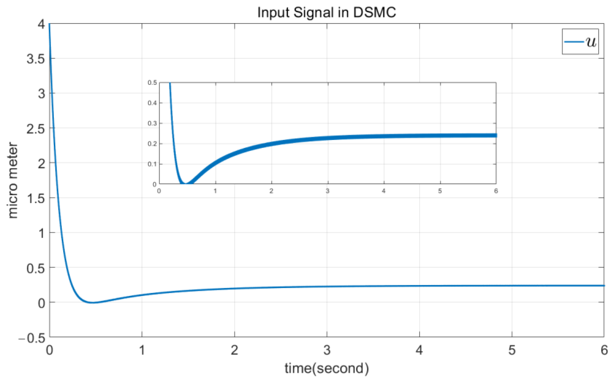
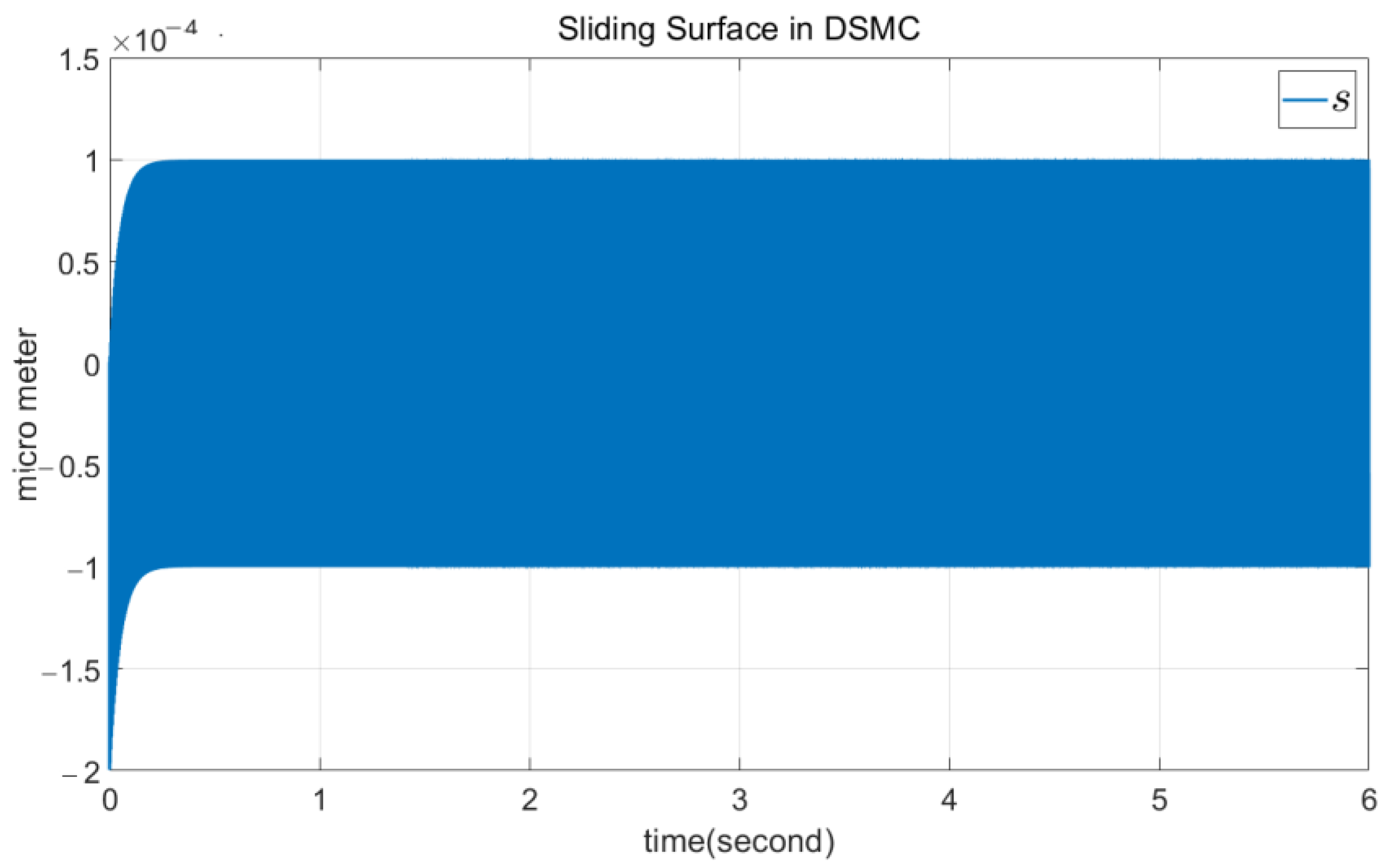
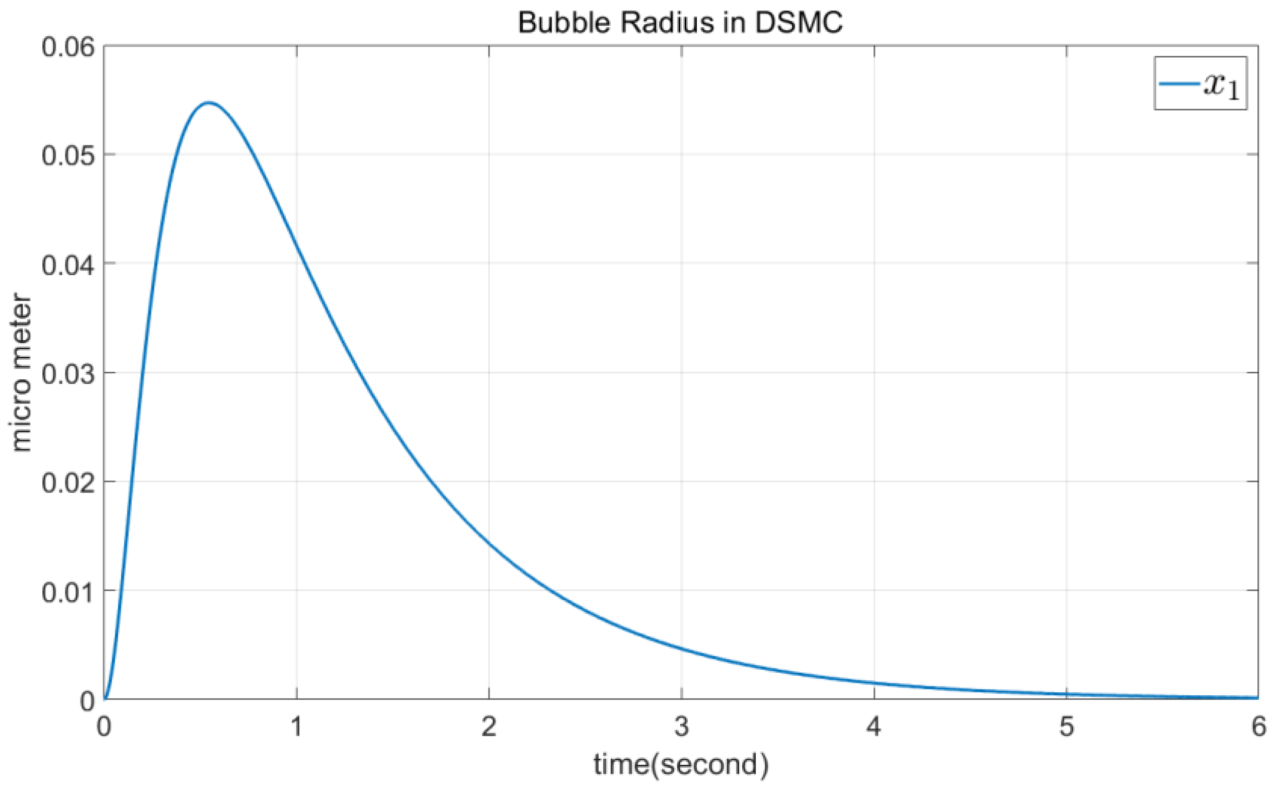
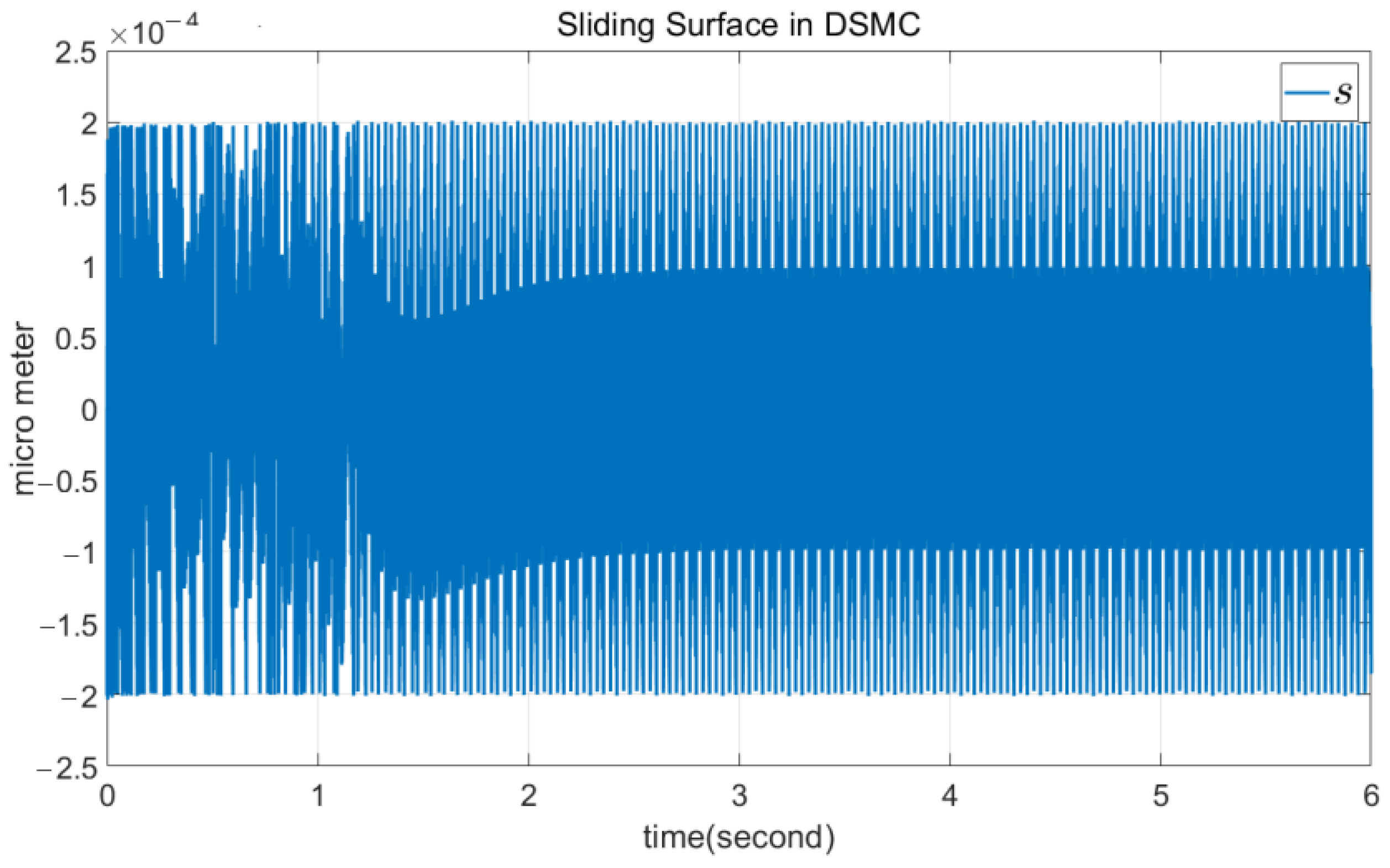
The first DSMC simulation was performed for Air with ε = 1.40 , and the results are shown in Figure 2, Figure 3 and Figure 4. From Figure 2, it can be seen that the radius of the bubble tends to increase at first, before 0.5 s, and then DSMC forces it to converge to zero. Thus, around 5 s, the radius of the bubble reaches zero, while the ultrasonic input control, shown in Figure 3, is smooth and without chattering. Moreover, Figure 4 shows the sliding surface, focusing on its low amplitude vibrations.
The second DSMC simulation was performed for Argon with ε = 1.66 . To show the robustness and invariance property of DSMC approach, the following unknown part was added to the function f(x) as the uncertain section.
Δ = 0.1 cos ( 100 t ) 0.2 exp ( 3 t )
Moreover, we suppose that instead of water, we have a mixture of liquids, i.e., the liquid viscosity μ is unknown. To model this phenomenon, we considered the following time-variable liquid viscosity:
μ ( t ) = μ 0.05 + cos ( t )
This means that the controller is based on and designed from Equations (7) and (10), but the system is as follows:
f ( x ) = 1 x 2 3 c 1.5 ρ x 2 2 2 σ x 1 4 μ ( t ) x 2 x 1 + 1 4 x 2 c 2 σ r 0 + p 0 p v r 0 x 1 3 ε 1 x 2 c ρ x 1       + p v ρ x 1 + Δ
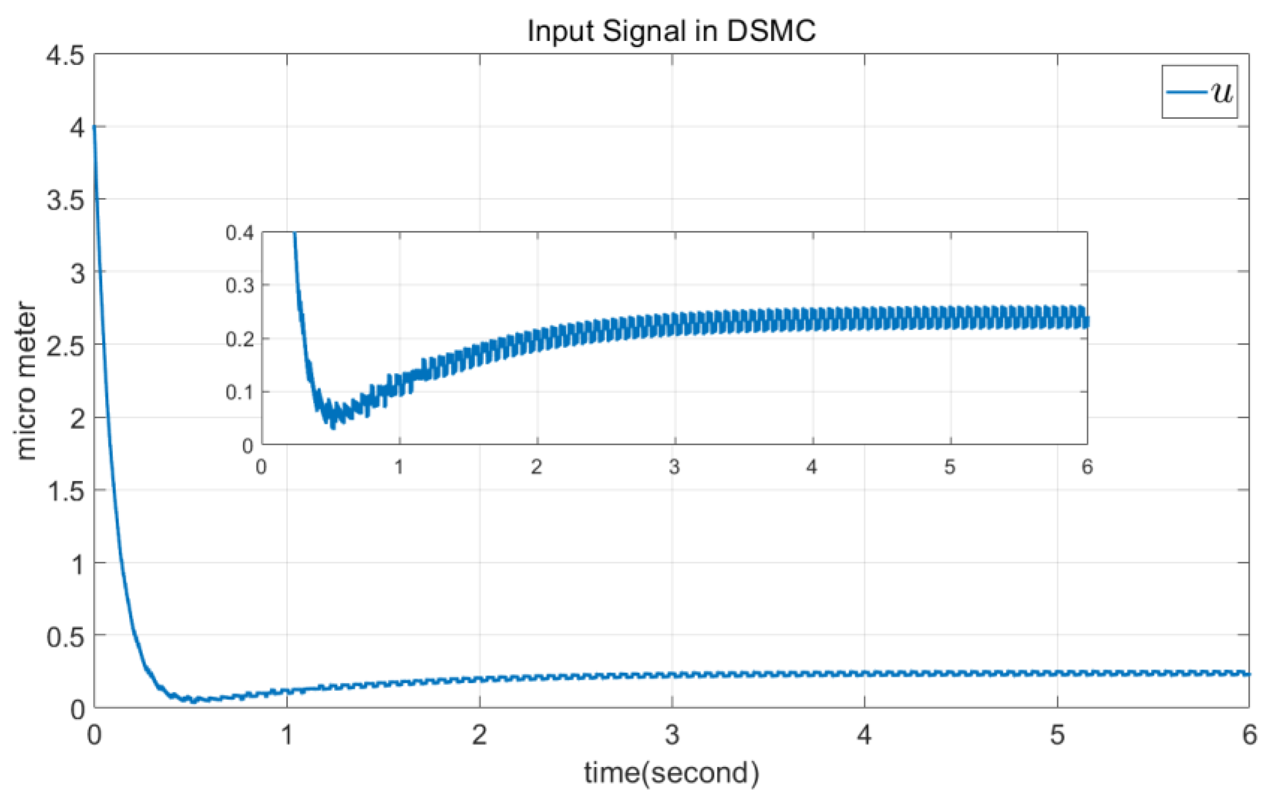
The results are shown in Figure 5, Figure 6 and Figure 7. As shown in these figures, the results are very similar to those for Air. This is due to the PI state feedback in Equation (7) and the invariance of the closed loop over the sliding surface in Equation (9).

4.2. TSMC Simulation

The block diagram of the proposed TSMC is illustrated in Figure 8. This is similar to Figure 1, but the low-pass integrator has been removed, and the type of state feedback is different.
As shown in Figure 8, by using the state variables x 1 and x 2 , the functions f ( x ) and g ( x ) are defined. Therefore, by defining the sliding surface s , signal v can be obtained. Finally, u ( t ) is calculated from linear state feedback.
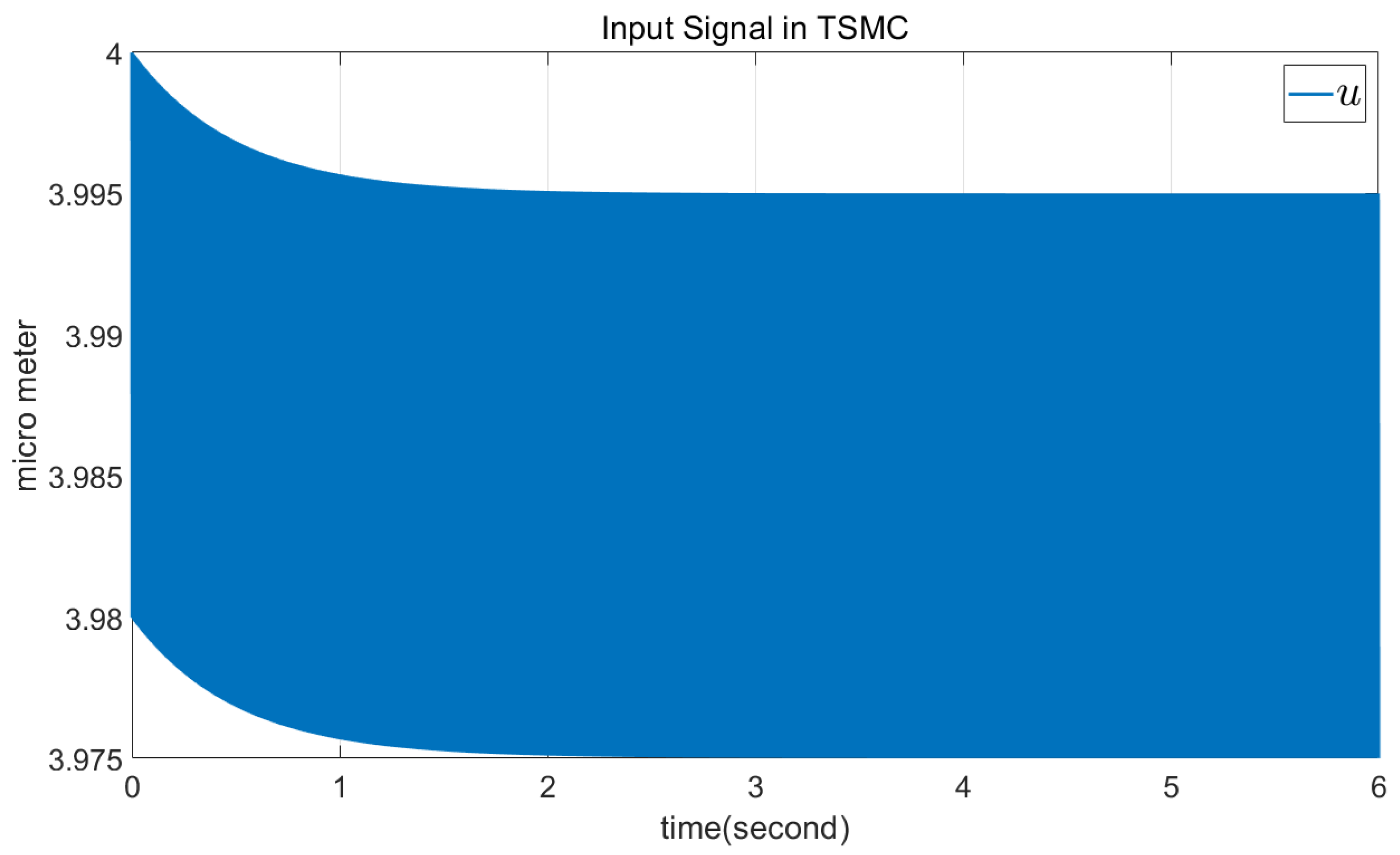
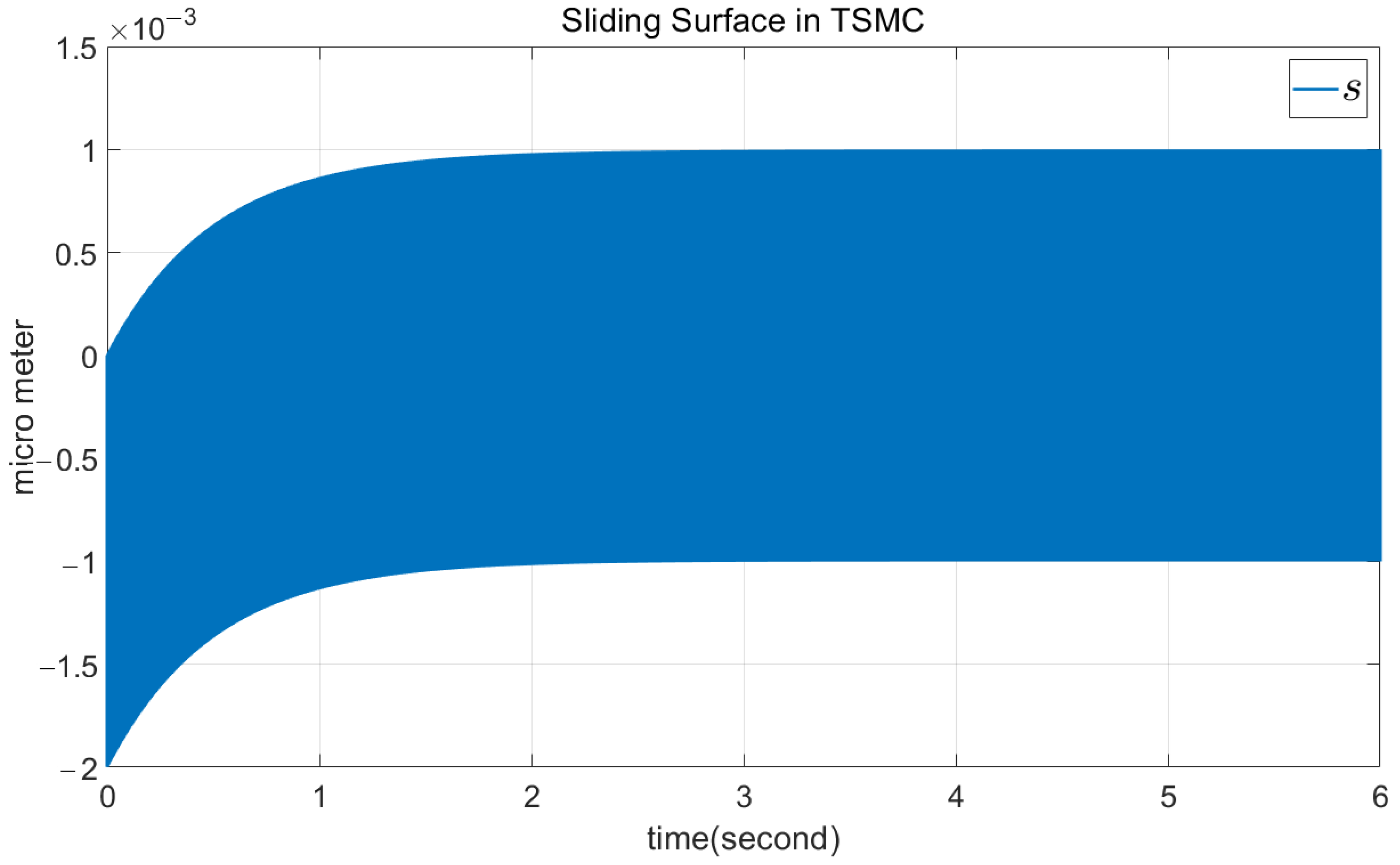
The TSMC is simulated using the same parameters as DSMC for Air. The parameters are chosen as a 1 = 3 and a 2 = 4 for the state feedback. Moreover, η 1 = 5 , η 2 = 5 , λ 1 = 0.1 , and λ 2 = 0.1 are chosen. The simulation results are shown in Figure 9, Figure 10 and Figure 11. Figure 9 shows that the radius of the bubble tends to increase at first, before 0.8 s. Then, TSMC forces it to converge to zero. Around 6 s, the radius of the bubble reaches zero, while the ultrasonic input control, shown in Figure 10 is not smooth and has high-frequency chattering. Moreover, Figure 11 shows the sliding surface.

4.3. Comparison of DSMC and TSMC

Comparing Figure 2 and Figure 5 demonstrates the robustness of the DSMC approach, as in both figures, the bubble radius converges to zero in about 5 s. However, a lower amplitude of chattering can be seen in Figure 3 compared to the chattering in Figure 6. Larger chattering around the sliding surface is observed in the case of unknown disturbances.
These simulations show the advantages of DSMC over TSMC in forcing the desired signals to zero. From Figure 2 and Figure 9, it can be seen that the maximum radius of bubble in DSMC is larger than in TSMC due to the delay of the integrator used in DSMC. However, the bubble radius converges to zero faster in DSMC. This is due to the slower convergence of the sliding surface in TSMC, as shown in Figure 11.
On the other hand, chattering is present in TSMC and can be suppressed in DSMC, which can be observed by comparing Figure 3 and Figure 10. Note that the ultrasonic wave shown in Figure 10 cannot be used to measure the bubble radius, as it presents high chattering components. This is one of the main advantages of DSMC over TSMC.

5. Conclusions

In this paper, a new approach for cavitation control is proposed. At first stage, the models of the Rayleigh–Plesset and Keller–Miksis were introduced for bubbles, which considers bubbles as spherical structures. To measure the radius of bubble, an ultrasonic wave is used. To provide a robust, smooth ultrasonic wave, dynamic sliding mode control is used, and this signal can be used to measure the bubble radius. In dynamic sliding mode control, an integrator is used as a low-pass filter to suppress high-frequency chattering from the input signal. To apply the dynamic sliding mode control, a proportional-integral state feedback is used. Then, a linear system with a new input control signal is obtained. To illustrate the fair advantages and priority of dynamic sliding mode control over traditional sliding mode control, similar parameters are used in both controllers. Chattering elimination is seen in dynamic sliding mode control, while it remains in traditional sliding mode control. Moreover, the design procedure developed in this work shows the simplicity of realization and concept for the proposed dynamic sliding mode control. Future work could focus on combining dynamic sliding mode control and terminal sliding mode control to suppress bubbles in a desired finite time.

Author Contributions

A.K.-M.: analysis, writing—original draft and preparation; O.B.: conceptualization, review, and editing. All authors have read and agreed to the published version of the manuscript.

Funding

The authors wish to express their gratitude to the Basque Government, through the project EKOHEGAZ II (ELKARTEK KK-2023/00051); to the Diputación Foral de Álava (DFA), through the project CONAVANTER; to the UPV/EHU, through the project GIU23/002; and to the Mobility Lab Foundation (CONV23/14) for supporting this work.

Data Availability Statement

The original contributions presented in the study are included in the article, further inquiries can be directed to the corresponding author.

Conflicts of Interest

The authors declare no conflict of interest.

References

  1. Wu, J.; Wesley, L. Ultrasound, cavitation bubbles and their interaction with cells. Adv. Drug Deliv. Rev. 2008, 60, 1103–1116. [Google Scholar] [CrossRef]
  2. Huang, S.; Mohamad, A.A. Modeling of cavitation bubble dynamics in multicomponent mixtures. J. Fluids Eng. 2009, 131, 031301. [Google Scholar] [CrossRef]
  3. Prosperetti, A.; Lezzi, A. Bubble dynamics in a compressible liquid. Part 1. First-order theory. J. Fluid Mech. 1986, 168, 457–478. [Google Scholar] [CrossRef]
  4. Haosheng, C.; Jiadao, W.; Darong, C. Cavitation damages on solid surfaces in suspensions containing spherical and irregular microparticles. Wear 2009, 266, 345–348. [Google Scholar] [CrossRef]
  5. Doinikov, A.A.; Aired, L.; Bouakaz, A. Dynamics of a contrast agent microbubble attached to an elastic wall. IEEE Trans. Med. Imaging 2012, 31, 654–662. [Google Scholar] [CrossRef]
  6. Orlandi, F.; Montorsi, A.; Milani, M. Cavitation analysis through CFD in industrial pumps: A review. Int. J. Thermofluids 2023, 20, 100506. [Google Scholar] [CrossRef]
  7. Akhatov, S.; Konovalova, S. Regular and chaotic dynamics of a spherical bubble. J. Appl. Math. Mech. 2005, 69, 575–584. [Google Scholar] [CrossRef]
  8. Kannan, Y.S.; Karri, B.; Sahu, K.C. Entrapment and interaction of an air bubble with an oscillating cavitation bubble. Phys. Fluids 2018, 30, 041701. [Google Scholar] [CrossRef]
  9. Rahmatizadeh, B.; Hamidi Beheshti, M.T.; Azadegan, M.; Najafi, N. Stability analysis and sliding mode control of a single spherical bubble described by Keller–Miksis equation. Int. J. Dyn. Cont. 2021, 9, 1757–1764. [Google Scholar] [CrossRef]
  10. Kirschner, I.N.; Kring, D.C.; Stokes, A.W.; Fine, N.E.; Uhlman, J.S. Control strategies for supercavitating vehicles. J. Vib. Contr. 2002, 8, 219–242. [Google Scholar] [CrossRef]
  11. Dzielski, J.; Kurdila, A. A benchmark control problem for supercavitating vehicles and an initial investigation of solutions. J. Vib. Contr. 2003, 9, 791–804. [Google Scholar] [CrossRef]
  12. Lin, G.; Balachandran, B.; Abed, E.H. Nonlinear dynamics and bifurcations of a supercavitating vehicle. IEEE J. Ocean. Eng. 2008, 32, 753–761. [Google Scholar] [CrossRef]
  13. Mao, X.; Qian, W. Nonlinear control design for a supercavitating vehicle. IEEE Trans. Contr. Sys. Tech. 2009, 17, 816–832. [Google Scholar]
  14. Vanek, B.; Balas, G.J.; Arndt, R. Linear, parameter-varying control of a supercavitating vehicle. Contr. Eng. Pract. 2010, 18, 1003–1012. [Google Scholar] [CrossRef]
  15. Mao, X.; Wang, Q. Adaptive control design for a supercavitating vehicle model based on fin force parameter estimation. J. Vib. Contr. 2015, 21, 1220–1233. [Google Scholar] [CrossRef]
  16. Han, Y.; Xu, Z.; Guan, L. Predictive control of a supercavitating vehicle based on time-delay characteristics. IEEE Access 2020, 9, 13499–13512. [Google Scholar] [CrossRef]
  17. Wang, J.; Liu, Y.; Cao, G.; Zhao, Y.; Zhang, J. Design of RBF adaptive sliding mode controller for a supercavitating vehicle. IEEE Access 2021, 9, 39873–39883. [Google Scholar]
  18. Badfar, E.; Alinaghizadeh Ardestani, M.; Azadegan, M.; Najafi, N. Utilizing sliding mode control for the cavitation phenomenon and using the obtaining result in modern medicine. SN Appl. Sci. 2019, 1, 1419. [Google Scholar] [CrossRef]
  19. Slotine, J.J.E.; Li, W. Applied Nonlinear Control; Prentice Hall: Englewood Cliffs, NJ, USA, 1991. [Google Scholar]
  20. Perruquetti, W.; Barbot, J.P. Sliding Mode Control in Engineering; CRC Press: Boca Raton, FL, USA, 2002. [Google Scholar]
  21. Karami-Mollaee, A.; Pariz, N.; Shanechi, H.M. Position control of servomotors using neural dynamic sliding mode. J. Dyn. Sys. Meas. Contr. 2011, 133, 141–150. [Google Scholar] [CrossRef]
  22. Karami-Mollaee, A.; Tirandaz, H.; Barambones, O. Dynamic sliding mode position control of induction motors based load torque compensation using adaptive state observer. Int. J. Comput. Math. Electr. Electron. Eng. 2018, 37, 2249–2262. [Google Scholar] [CrossRef]
  23. Alsaadi, F.E.; Yasami, A.; Alsubaie, H.; Alotaibi, A.; Jahanshahi, H. Control of a hydraulic generator regulating system using Chebyshev-neural-network-based non-singular fast terminal sliding mode method. Mathematics 2023, 11, 168–186. [Google Scholar] [CrossRef]
  24. Zhu, Q. Model-free sliding mode enhanced proportional, integral, and derivative (SMPID) control. Axioms 2023, 12, 721. [Google Scholar] [CrossRef]
  25. Nie, J.; Hao, L.; Lu, X.; Wang, H.; Sheng, C. Global fixed-time sliding mode trajectory tracking control design for the saturated uncertain rigid manipulator. Axioms 2023, 12, 883. [Google Scholar] [CrossRef]
  26. Lee, H.; Utkin, V.I. Chattering suppression methods in sliding mode control systems. Annu. Rev. Control 2007, 31, 179–188. [Google Scholar] [CrossRef]
  27. Fuh, C.-C. Variable-thickness boundary layers for sliding mode control. J. Mar. Sci. Tech. 2008, 16, 288–294. [Google Scholar] [CrossRef]
  28. Chen, H.-M.; Renn, J.-C.; Su, J.-P. Sliding mode control with varying boundary layers for an electro-hydraulic position servo system. Int. J. Adv. Manuf. Tech. 2005, 26, 117–123. [Google Scholar] [CrossRef]
  29. Zhang, X. Sliding mode-like fuzzy logic control with adaptive boundary layer for multiple-variable discrete. J. Intell. Syst. 2016, 25, 209–220. [Google Scholar] [CrossRef]
  30. Gandikota, G.; Das, D.K. Disturbance observer–based adaptive boundary layer sliding mode controller for a type of nonlinear multiple-input multiple-output system. Int. J. Robust. Nonlinear Contr. 2019, 29, 5886–5912. [Google Scholar] [CrossRef]
  31. Cucuzzella, M.; Incremona, G.P.; Ferrara, A. Design of robust higher order sliding mode control for microgrids. IEEE J. Emerg. Sel. Top. Cir. Sys. 2015, 5, 393–401. [Google Scholar] [CrossRef]
  32. Karami-Mollaee, A. Design of dynamic sliding mode controller for active suspension system. Modares Mech. Eng. 2016, 16, 51–58. [Google Scholar]
  33. Levant, A. Homogeneity approach to high-order sliding mode design. Automatica 2005, 41, 823–830. [Google Scholar] [CrossRef]
  34. Plestan, F.; Glumineau, A.; Laghrouche, S. A new algorithm for high-order sliding mode control. Int. J. Robust. Non. Contr. 2008, 18, 441–453. [Google Scholar] [CrossRef]
  35. Levant, A. Higher-order sliding modes, differentiation and output-feedback control. Int. J. Robust. Non. Contr. 2010, 76, 924–941. [Google Scholar] [CrossRef]
  36. Kerboua, K.; Hamdaoui, O. Insights into numerical simulation of controlled ultrasonic waveforms driving single cavitation bubble activity. Ultrason.-Sonochemistry 2018, 43, 237–247. [Google Scholar] [CrossRef]
  37. Hilgenfeldt, S.; Lohse, D.; Brenner, M. Phase diagrams for sonoluminescing bubbles. Phys. Fluids 1996, 11, 2808–2826. [Google Scholar] [CrossRef]
  38. Grossmann, S.; Hilgenfeldt, S.; Lohse, D.; Zomack, M. Sound radiation of 3-MHz driven gas bubbles. J. Acoust. Soc. Am. 1997, 2, 1223–1230. [Google Scholar] [CrossRef]
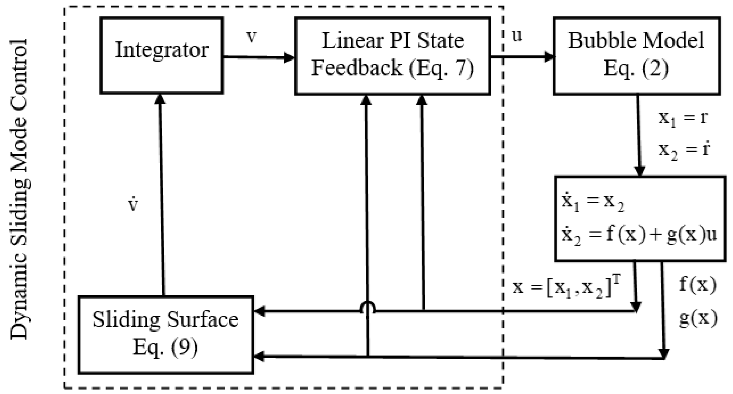
Figure 1. DSMC proposed approach structure.
Axioms 13 00706 g001
Figure 2. The radius of the bubble in DSMC for Air.
Axioms 13 00706 g002
Figure 3. The ultrasonic wave in DSMC for Air.
Axioms 13 00706 g003
Figure 4. The sliding surface in DSMC for Air.
Axioms 13 00706 g004
Figure 5. The radius of the bubble in DSMC for Argon.
Axioms 13 00706 g005
Figure 6. The ultrasonic wave in DSMC for Argon.
Axioms 13 00706 g006
Figure 7. The sliding surface in DSMC for Argon.
Axioms 13 00706 g007
Figure 8. TSMC proposed approach structure.
Axioms 13 00706 g008
Figure 9. The radius of the bubble in TSMC for Air.
Axioms 13 00706 g009
Figure 10. The ultrasonic wave in TSMC for Air.
Axioms 13 00706 g010
Figure 11. The sliding surface in TSMC for Air.
Axioms 13 00706 g011
Table 1. Specific heat ratio.
ValueNotationGas or Vapor
1.40 Air
1.40 O 2 Oxygen
1.40 N 2 Nitrogen
1.41 H 2 Hydrogen
1.66 H e Helium
1.66 A r Argon
Table 2. Model parameters.
UnitValueParameter
μ m 4.5 r 0
μ m / s 0 r ˙ 0
a t m 1 p 0
a t m 1.2 p a
P a 4240 p v
k g / m 3 1000 ρ
P a × s 0.001 μ
N / m 0.073 σ
Disclaimer/Publisher’s Note: The statements, opinions and data contained in all publications are solely those of the individual author(s) and contributor(s) and not of MDPI and/or the editor(s). MDPI and/or the editor(s) disclaim responsibility for any injury to people or property resulting from any ideas, methods, instructions or products referred to in the content.