Article

Passive Damping of Longitudinal Vibrations of a Beam in the Vicinity of Natural Frequencies Using the Piezoelectric Effect

Institute of Digital Technologies and Modeling in Construction, Moscow State University of Civil Engineering, Yaroslavskoye Shosse, 26, 129337 Moscow, Russia
*
Author to whom correspondence should be addressed.
Axioms 2023, 12(10), 981; https://doi.org/10.3390/axioms12100981
Submission received: 27 June 2023 / Revised: 11 September 2023 / Accepted: 22 September 2023 / Published: 18 October 2023
(This article belongs to the Special Issue Applied Numerical Analysis in Civil Engineering)

Abstract

:
To significantly reduce the amplitude of longitudinal vibrations of the beam in the vicinity of its natural frequencies, a fundamentally new method of damping vibrations is used. For this purpose, the beam surfaces are covered with layers of polarized piezoceramics with a strong piezoelectric effect. We will use two types of electrical conditions on the electrodes of the piezoelectric layers: short-circuited electrodes and disconnected electrodes. On short-circuited electrodes, the electric potential is zero. As a result of the piezoelectric effect, an electric charge appears on the disconnected electrodes when the beam is deformed. The electroelastic state of a beam with different electrical conditions is described by different boundary value problems. A new approach to damping vibrations in the vicinity of natural frequencies is based on the following rule for controlling the dynamic characteristics of a structure: when the beam vibration frequency approaches its natural vibration frequency, we change the electrical conditions on the electrodes of the piezoelectric layers, thereby changing the spectrum of its natural frequencies. Let, for example, the vibration frequency of a beam with short-circuited electrodes approach its natural frequency. In this case, the amplitudes of the sought quantities grow without limit. The natural frequency spectrum of a beam with disconnected electrodes will differ from the spectrum of a beam with short-circuited electrodes. As a result, the amplitudes of the sought quantities will decrease. It is shown that the efficiency of vibration damping can be significantly increased by choosing the direction of the preliminary polarization of the piezoelectric material and the location of its electrodes. Numerical examples are given that demonstrate the effectiveness of the proposed method. The advantage of the method lies in its simplicity and the low cost of the piezoelectric material, which serves as a non-inertial damper.

1. Introduction

Vibration damping in various fields of technology, such as building structures, machines, military equipment, electronics, is an urgent scientific and technical problem. For example, in construction, the level of vibration significantly affects the durability of various structures, such as high-rise and large-span structures, chimneys, television towers, bridges, etc., which are subjected to wind and seismic loads.
In modern practice, active vibration damping, passive vibration damping and their combinations are widely used.
With active damping of vibrations, force effects are applied to the object, causing vibrations in the antiphase of its vibrations and thus reducing the amplitude of vibrations. For this purpose, active power devices (actuators) are widely used, which use mechanical, hydraulic, electrodynamic, piezoelectric and other types of drives to actively suppress vibrations [1,2,3,4,5,6].
The passive system controls vibration through the use of special materials in the construction, while the active system usually uses a special type of moving mechanism.
Passive vibration damping does not require energy sources. For passive damping, inertial dampers are used, the devices built into the building structure and designed to reduce the amplitude of its mechanical vibrations. The use of these devices in structures can reduce the discomfort of people from vibrations of the building, as well as prevent its destruction in the event of earthquakes, hurricanes and other extreme impacts. For this purpose, structural vibration control devices are used to dissipate the huge energy entering the structures, including active, passive, semi-active and hybrid vibration control systems [7,8,9,10,11,12,13].
For passive vibration damping of a structure in the vicinity of its natural frequencies, this paper proposes a new method based on the use of the piezoelectric effect [14]. The method is based on the following well-known position of mathematics: when the boundary conditions of the boundary value problem change, the spectrum of natural frequencies also changes. In order to control the spectrum of natural frequencies, we supplement the design with elements of pre-polarized piezoceramics with electrodes. With passive damping of vibrations, the piezoceramic electrodes can be either short-circuited or disconnected. The spectrum of natural frequencies of the design with short-circuited electrodes differs from the spectrum of natural frequencies of the design with disconnected electrodes. To dampen vibrations near natural frequencies, we will use a simple idea: if the vibration frequency of a structure with piezoelectric elements, the electrodes of which are short-circuited, approaches its natural frequency, we will disconnect the electrodes. The new boundary value problem has other eigenfrequencies; its eigenfrequency is no longer equal to the vibration frequency, and the amplitudes of the sought quantities will decrease significantly. Conversely, when the oscillation frequency of a structure with open electrodes approaches its natural frequency, the electrodes should be closed.
The proposed article is the first of a forthcoming series of works on active and passive vibration damping of structures using the piezoelectric effect.
It should be noted that piezoelectric materials are widely used in modern technology. There are piezoelectric transformers, bandpass filters, sound emitters and receivers, ultrasonic delay lines, piezoelectric sensors, piezoelectric motors, piezoelectric elements of gyroscopes, piezoelectric elements of computer technology—this is not a complete list of devices based on the piezoelectric effect. Piezoelectric materials are distinguished by the stability of their properties in wide temperature and time ranges, low costs, and the manufacturability of their application.

2. Passive Vibration Damping of a Beam with Piezoelectric Layers with Transverse Polarization

2.1. Piezoelectric Layers with Continuous Electrodes

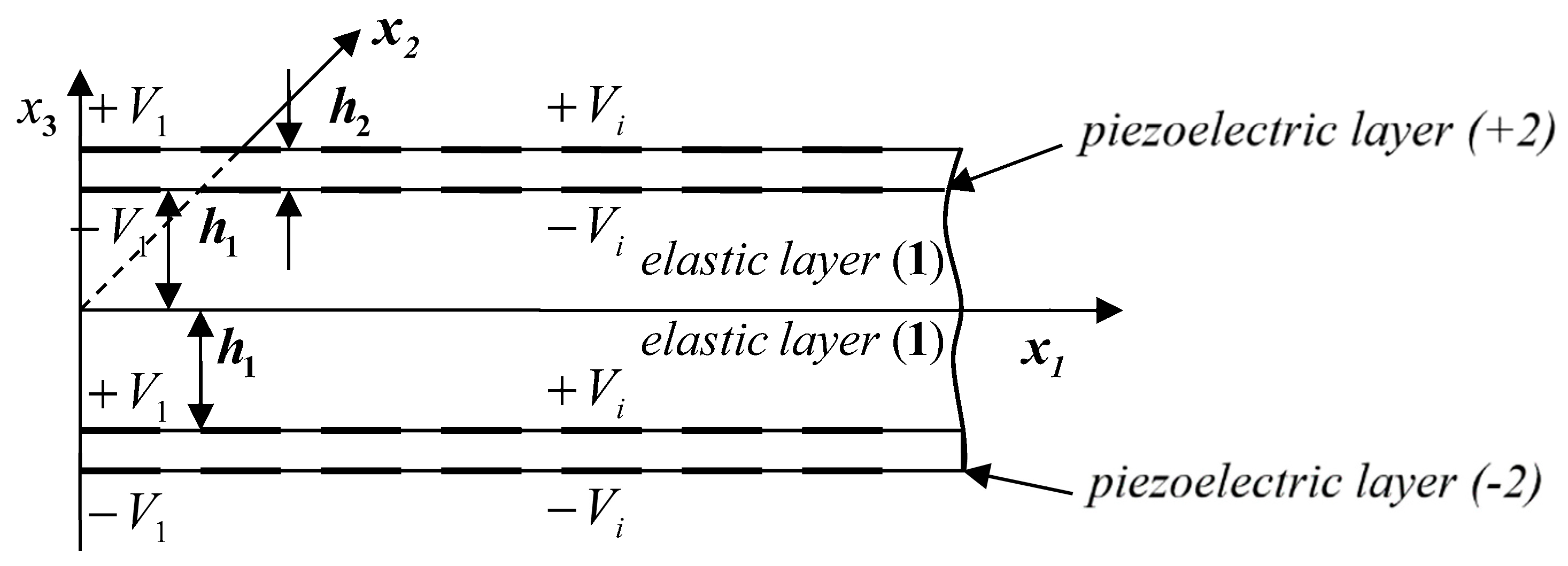
A three-layer beam with one elastic layer and two piezoelectric layers located symmetrically with respect to the elastic layer is considered. The middle layer is elastic, the outer layers are made of a piezoelectric material. The number of the elastic layer is (1), and the numbers of the upper and lower layers are ( ± 2 ), respectively. The thickness of the elastic layer is equal to 2 h 1 , the thickness of each piezoelectric layer is equal to h 2 , the length of the beam is l , and the width of the beam is g (Figure 1). The total thickness of the beam is 2h = 2h1 + 2h2. In Figure 1, the electrodes are drawn with a thick line.
The longitudinal section of the beam in Cartesian coordinates and the values of the electrical potential are schematically shown in Figure 1.
The axis x1 is directed along the length of the beam; the axis x2 is directed along the width of the beam; the axis x3 is orthogonal to them.
It is assumed that the piezoelectric layers are pre-polarized in the direction of the x3-axis. In [14,15], we constructed the theory of the multilayer electroelastic beam. Here we briefly present the results for a particular case of a three-layer beam.
In the case of thin-walled beams in the equations of state, the stresses σ 22 and σ 33 can be neglected compared to the stresses σ 11 . In addition, it is assumed that the electroelastic state does not depend on the coordinate x2.
Taking into account the assumptions made, the equations for the elastic and electroelastic layers will be written as
Motion equation:
σ ( k ) x 1 = ρ ( k ) 2 u ( k )   t 2     ,                 k = 2 , 1 , 2
Strain—displacement formulas:
e ( k ) = u ( k ) x 1 ,             k = 2 , 1 , 2
Equation of state (Hooke’s law) for the elastic layer:
σ ( 1 ) = E e ( 1 )
Equations of state for piezoelectric layers:
σ ( ± 2 ) = 1 s 11 E e ( ± 2 ) d 31 s 11 E E 3 ( ± 2 )
D 3 ( ± 2 ) = ε 33 T E 3 ( ± 2 ) + d 31 σ ( ± 2 )
where
E 3 ( ± 2 ) = ϕ ( ± 2 ) x 3
The electroelastic state of piezoelectric layers is described by a coupled electroelastic problem. Formulas (4) and (5) are well-known formulas [16]. Since the problem is electroelastic, Formulas (4) and (5) simultaneously contain mechanical and electrical quantities.
In Formulas (1)–(6), σ is the stress component in the direction x1; u and e are the displacement and deformation in the direction x1, respectively; E3 and D3 are the components of the electric field vector and electric induction vector in the direction x3; E is the modulus of elasticity of elastic layer; ϕ is the electric potential; s 11 E is the elastic compliance at zero electric field; d31 is the piezoelectric constant; and ε 33 T is the dielectric constant at zero voltages. The notation used is the same as that used in [15].
For our purposes, we will consider piezoelectric layers, in which the faces x3 = ±h and x3 = ±h1 (Figure 1) are completely covered with electrodes. Here we will consider only two kinds of conditions on the electrodes:
-
the electrodes are short-circuited. On short-circuited electrodes, the electric potential is zero
ϕ ( ± 2 ) x 3 = ± h = ϕ ( ± 2 ) x 3 = ± h   1 = 0
-
the electrodes are disconnected. On disconnected electrodes, the electric potential is not zero. It is equal to
ϕ ( ± 2 ) x 3 = ± h = ± V ( ± 2 ) ,   ϕ ( ± 2 ) x 3 = ± h 1 = V ( ± 2 )
where the values V(±2) are determined from the following integral condition:
I = Ω D 3 t d Ω = 0
Here I is the electricity. The integral is evaluated over the surface Ω of one of the electrodes and t denotes the time.
On the surfaces of the beam, the mechanical surface load is usually specified as
σ 13 ( ± 2 ) x 3 = ± h = ± q 1 ± ,                       σ 33 ( ± 2 ) x 3 = ± h = ± q 3 ± ,   σ 33 ( ± 2 ) x 3 = ± h = ± q 3 ±
The superscript in parentheses indicates the layer number. Hereinafter, each formula with double signs ± , contains two formulas. To obtain one formula, the upper signs must be selected; to obtain the second formula, only the lower signs must be considered.
For simplicity, we consider the damping of harmonic vibrations of a three-layer beam (all values vary with time t according to the law e i ω   t , where ω is the circular frequency). Therefore, we will write down all the equations and boundary conditions with respect to the amplitude values of the unknown quantities.
The transition from three-dimensional Equations (1)–(10) to the theory of multilayer electroelastic beams was made in [15].
We write the equations for the plane problem for the beam with short-circuited electrodes in the notation accepted in the theory of beams:
d T d x 1 + X + 2 h ρ ω 2 u = 0 ,                   T = A ε ,                 ε = d u d x 1
X = q 1 + + q 1 ,                 A = 2 h 1 E + 2 h 2 s 11 E ,                 ρ ( k ) = 1 h ( ρ ( 1 ) h 1 + ρ ( 2 ) h 2 )
σ ( ± 2 ) = 1 s 11 E ε ,   E 3 , 0 ( ± 2 ) = 0 ,   D 3 , 0 ( ± 2 ) = d 31 s 11 E ε
The equations for the plane problem for the beam with disconnected electrodes are written as
d T d x 1 + X + 2 h ρ ω 2 u = 0 ,                   T = A ε + P ,                 ε = d u d x 1       P = 2 s 11 E h 2 l k 31 2 1 k 31 2 u x 1 = l u x 1 = 0
σ ( ± 2 ) = 1 s 11 E ε + 2 d 31 h 2 s 11 E V ( ± 2 ) ,   E 3 , 0 = 2 V h 2 ,   P = 4 d 31 s 11 E V = 2 d 31 h 2 s 11 E E 3 , 0
D 3 , 0 ( ± 2 ) = ε 33 T ( 1 k 31 2 ) E 3 , 0 ( ± 2 ) + d 31 s 11 E ε ,         V = h 2 2 l d 31 k 31 2 1 k 31 2 u x 1 = l u x 1 = 0
Here, ε is the strain and T = h 1 h σ ( 2 ) d x + h 1 h 1 σ ( 1 ) d x + h h 1 σ ( 2 ) d x is the total longitudinal force acting in the beam.
We will consider the forced harmonic vibrations of the beam under the action of a constant distributed load with the following boundary conditions:
u x 1 = 0 = 0 ,             T x 1 = l = 0
For numerical examples, we introduce dimensionless coordinates and dimensionless quantities.
ξ = x 1 l ,   u * = u l   ,   T * = T A ,   X * = X l A   ,   ε = ε * ,   D 3 * = s 11 E d 31 D 3 ,   E 3 * = d 31 E 3
Let the beam electrodes be short-circuited. Substituting Formula (16) into Equation (13), we obtain the following system of equations:
d T * d ξ + X * + λ 2 u * = 0 ,               T * = ε * ,                 ε * = d u * d ξ ,             λ 2 = 2 h ρ ω 2 l 2 A
Here λ 2 is the dimensionless frequency parameter.
The resulting governing equation is
d 2 u * d ξ 2 + λ 2 u * + X * = 0
Its solution is
u * = c 1 sin λ ξ + c 2 cos λ ξ 1 λ 2 X * T * = λ ( c 1 cos λ ξ c 2 sin λ ξ )
Arbitrary integration constants c 1 and c 2 are determined from the conditions at the ends of the beam
u * ξ = 0 = 0 ,             T * ξ = 1 = 0
Satisfying condition (20), we obtain
c 1 = sin λ λ 2 cos λ X * ,                   c 2 = 1 λ 2 X *
The natural frequencies are determined from the equation cos λ = 0 and they are equal to
n π + π / 2 ,             n = 0 , 1 , 2 , 3 ,
Consider now the plane problem for the beam with disconnected electrodes. Note that the electric potential is an odd function in the plane problem.
V ( 2 ) = V ( 2 ) = V
The system of equations in terms of the dimensionless sought quantities has the form
d T * d ξ + X * + λ 2 u * = 0 ,               T * = ε * + P * ,                 ε * = d u * d ξ ,             λ 2 = 2 h ρ ω 2 l 2 A P * = r u * ξ = 1 ,   r = 2 h 2 A s 11 E k 31 2 1 k 31 2 ,   k 31 2 = d 31 2 s 11 E ε 33 T
σ ( ± 2 ) = 1 s 11 E ε + 2 d 31 h 2 s 11 E V ( ± 2 ) ,   E 3 , 0 = 2 V h 2 ,   P = 4 d 31 s 11 E V = 2 d 31 h 2 s 11 E E 3 , 0 D 3 , 0 ( ± 2 ) = ε 33 T ( 1 k 31 2 ) E 3 , 0 ( ± 2 ) + d 31 s 11 E ε ,         V = h 2 2 l d 31 k 31 2 1 k 31 2 u x 1 = l u x 1 = 0
The resulting governing equation has the form (18). The force T * is determined by the formula
T * = λ ( c 1 cos λ ξ c 2 sin λ ξ ) + P * = λ ( c 1 cos λ ξ c 2 sin λ ξ ) + r ( c 1 sin λ + c 2 cos λ )
Arbitrary integration constants c 1 and c 2 are determined from the conditions at the ends of the beam (15):
c 1 = X * λ 2 λ sin λ r ( cos λ 1 ) λ cos λ + r sin λ ,   c 2 = X * λ 2
The natural frequencies are determined from the equation
λ cos λ + r sin λ = 0
Let us introduce the concept of efficiency f of passive damping of vibrations using the piezoelectric effect. We assume that the damping efficiency is equal to the ratio of the absolute value of the difference of resonant frequencies, with the same numbers, for the beam with disconnected and short-circuited electrodes, respectively, as the resonant frequencies of the beam with short-circuited electrodes
f = ω ( sh ) ω ( d ) ω ( sh ) = λ ( sh ) λ ( d ) λ ( sh )
Here the subscripts (sh) and (d) mean that the quantity belongs to the electroelastic state with short-circuited and disconnected states, respectively.
It is clear that the damping efficiency increases when the relative difference between the absolute values of resonant frequencies for a beam with disconnected and short-circuited electrodes gets larger.
In Table 1, we list the vibration damping efficiency for the cantilever beam considered above.
Here, n is the number of the resonant vibration frequency, λ ( sh ) and λ ( d ) are the values of the dimensionless frequency parameter at the beam resonances. The calculation was performed for a beam made of reinforced concrete with layers of polarized piezoceramics with a strong piezoelectric effect PZ29 [17], h2/h1 = 0.1.
From Table 1 it can be seen that the highest efficiency in the case of continuous electrodes is achieved at the main (lower) resonant frequency of the beam vibrations and rapidly decreases with increasing resonant frequency numbers.

2.2. Piezoelectric Layers with Split Electrodes

Consider a beam with piezoelectric layers having a pair of electrodes on each surface. The length of each electrode is equal to half the length of the beam. Let us perform the calculation for this beam as it was performed in Section 2.1. The calculation results are summarized in Table 2.
It can be seen from the table that in the presence of a pair of electrodes on each surface of the piezoelectric layers, the efficiency is lower and decreases with increasing resonant frequency numbers.
We will now show that the use of a large number of split electrodes will be more effective for passive vibration damping.
Consider a beam with m electrodes on each surface of the piezoelectric layers x3 = ±h and x3 = ±h1. The length of each electrode is δ = l/m. We choose m such that the length of the electrode is less than or equal to the thickness of the beam h (Figure 2).
In the case of short-circuited electrodes, it does not matter if the electrodes are continuous or cut since in this case, the electric potential on the electrodes is zero. If all electrodes are short-circuited, then for the electroelastic state of the beams, Equation (17) and solution (19) remain valid.
Consider a beam with disconnected electrodes. Let us find the value of the electric potential on the i-th electrode using Formula (9). As a result of integration over the surface of the i-th electrode, we obtain
V i = h 2 2 l d 31 k 31 2 1 k 31 2 u x 1 = x 1 , i + 1 u x 1 = x 1 , i δ
Let us move on from the finite displacement differences along the length of the beam to the derivative with respect to the variable x and obtain an approximate expression for the electric field strength E3.
      E 3 = d 31 s 11 E ε 33 T 1 k 31 2 d u d x
Taking into account Formula (29), the elasticity relation for the force T will be written in the form
      T = B ε
Using Formula (30), we write the following system of equations for the dimensionless quantities for the beam with disconnected electrodes:
d T * d ξ + X * + λ 1 2 u * = 0 ,               T * = ε * ,                 ε * = d u * d ξ ,             λ 1 2 = 2 h ρ ω 2 l 2 B
X = q 1 + + q 1 ,                 B = 2 h 1 E + 2 h 2 s 11 E ( 1 + k 31 2 1 k 31 2 ) ,                 ρ = 1 h ( ρ 1 h 1 + ρ 2 h 2 ) u * = u l ,   T * = T B ,   X * = X l B
The general solution of Equation (31) has the form
u * = c 1 sin λ 1 ξ + c 2 cos λ 1 ξ 1 λ 1 2 X * T * = λ 1 ( c 1 cos λ 1 ξ c 2 sin λ 1 ξ )
Arbitrary integration constants c 1 and c 2 are determined from the conditions at the ends of the beam
u * ξ = 0 = 0 ,             T * ξ = 1 = 0
Satisfying condition (32), we get
c 1 = sin λ 1 λ 1 2 cos λ 1 X * ,                     c 2 = 1 λ 1 2 X *
The natural frequencies are determined from the equation cos λ 1 = 0 and they are equal to   n π + π / 2 ,             n = 0 , 1 , 2 , 3 ,

2.3. Numerical Example

Let us perform the analysis of a cantilever beam with a large number of split electrodes. To dampen the vibrations of the beam as the vibration frequency approaches the resonant frequency, we change the electrical conditions. The calculation is made for the same materials as in Section 2.1. The results are presented in Table 3.
It should be noted that for a beam with a large number of electrodes, the efficiency is higher than for a beam with continuous electrodes or for a beam with two electrodes on each surface of the piezoceramic layer (Table 1 and Table 2). We especially note that for a beam with a large number of electrodes, the damping efficiency is approximately the same for all resonant frequencies.
In Section 2.2, the dimensional quantities were replaced by dimensionless ones. The formulas for the dimensionless desired values for a beam with short-circuited electrodes (16) and for a beam with split electrodes (32) are different. To compare the values of the dimensionless sought values for different electrical conditions on the electrodes, we write out formulas that relate the dimensionless sought values of the beam with disconnected electrodes with the corresponding values of the beam with short-circuited electrodes:
  λ 1 2 = A B λ 2 ,   X * ( d ) = A B X * ( sh ) ,   T * ( d ) = A B T * ( sh )
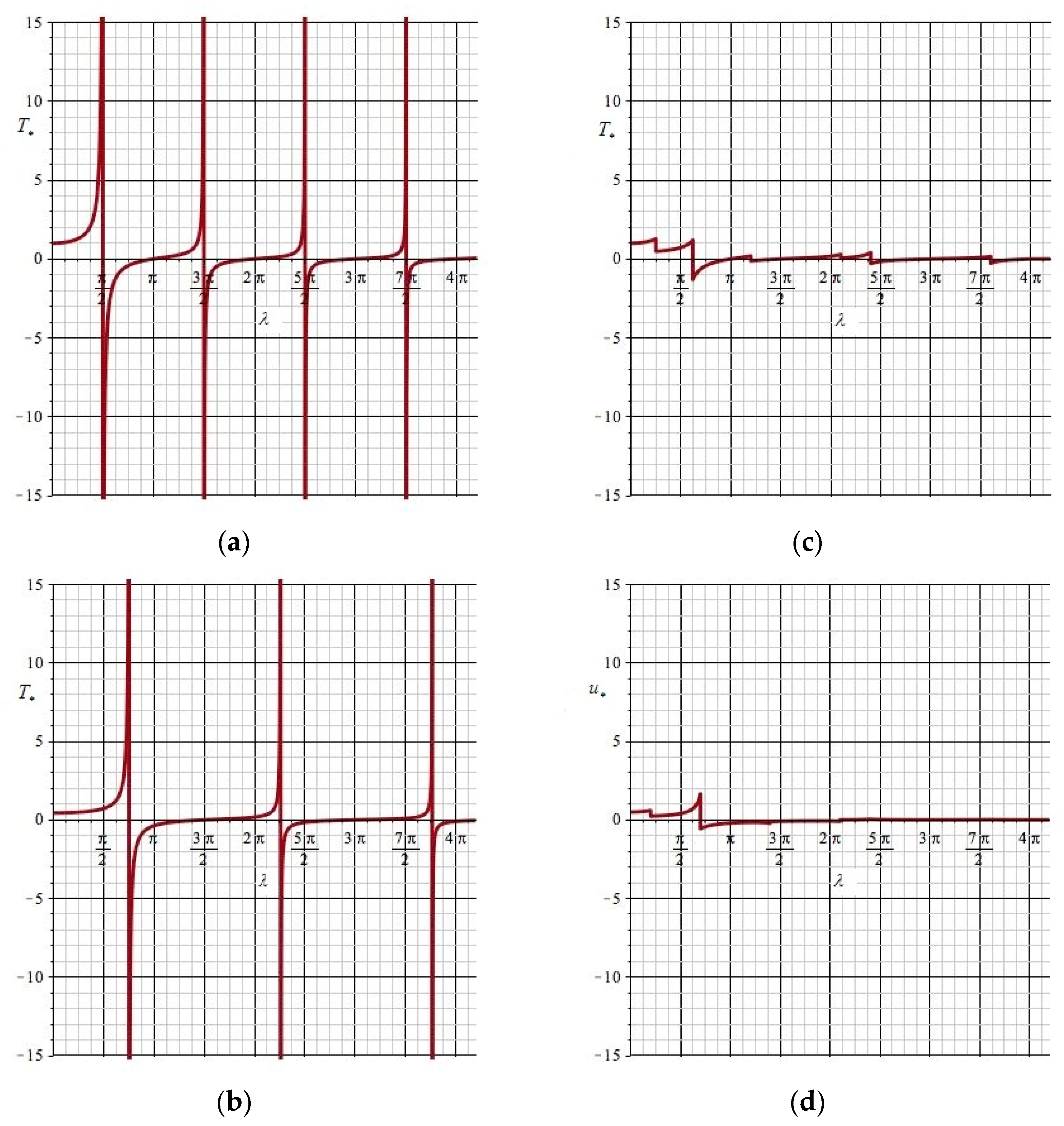
Let us compare the results of the calculation of forces and displacements and resonant frequencies of a beam with short-circuited electrodes and a beam with disconnected split electrodes. Let us show on the graphs the efficiency of vibration damping by the proposed method (Figure 3).
From graphs Figure 3a,b it can be seen that the resonant frequencies of the beam with short-circuited electrodes are less than the corresponding resonant frequencies of the beam with disconnected electrodes. Graphs Figure 3c,d show how the amplitudes of force and displacement vibrations at resonant frequencies have decreased as a result of vibration damping.

3. Passive Vibration Damping of a Beam with Piezoelectric Layers with Longitudinal Pre-Polarization

3.1. Construction of the Theory of Structurally Anisotropic Beams

Consider a beam with piezoceramic layers with longitudinal pre-polarization in the x1 direction. The schematic structure of the beam is shown in Figure 4. The arrows on the sections of the piezoelectric layers show the direction of the pre-polarization of the piezoelectric ceramics. Composite piezoceramics of this structure are widely used in electronics, robotics, measuring devices, etc., since its electromechanical coupling coefficient is large and reaches the values of the order of 0.75, for example, for PZ29 piezoceramics [17].
The main relations for piezoelectric layers with longitudinal polarization have
σ 11 ( ± 2 ) = 1 s 33 E e 1 ( ± 2 ) d 33 s 33 E E 1 ( ± 2 ) D 1 ( ± 2 ) = ε 33 T E 1 ( ± 2 ) + d 33 σ 11 ( ± 2 ) ,   d D 1 ( ± 2 ) d x 1 = 0
where
E 1 ( ± 2 ) = d ϕ ( ± 2 ) d x 1
The equations of motion and the equations for the elastic middle layer of the beam, presented in Section 2.1, remain valid.
The electrical conditions are the same as for the beams with piezoceramic layers with transverse polarization: on short-circuited electrodes, the electric potential is zero; on disconnected electrodes, the integral over the electrode surface of the component D1 of the electric induction vector is zero.
As a result of simple transformations similar to those performed above, we obtain the following equations for a beam with short-circuited electrodes:
d T * d ξ + X * + λ 2 u * = 0 ,               T * = ε * ,                 ε * = d u * d ξ ,             λ 2 = 2 h ρ ω 2 l 2 A X = q 1 + + q 1 ,                 A = 2 h 1 E + 2 h 2 s 33 E ,                 ρ = 1 h ( ρ 1 h 1 + ρ 2 h 2 ) ξ = x 1 l ,   u * = u l   ,   T * = T A
The system of Equation (36) is reduced to the following equation:
d 2 u * d ξ 2 + λ 2 u * + X * = 0
Its solution has the form (19).
For the beam with disconnected electrodes, the equations are written as
d T * d ξ + X * + λ 1 2 u * = 0 ,               T * = ε * ,                 ε * = d u * d ξ ,             λ 1 2 = 2 h ρ ω 2 l 2 B X = q 1 + + q 1 ,                 B = 2 h 1 E + 2 h 2 s 33 E ( 1 + k 33 2 1 k 33 2 ) ,                 ρ = 1 h ( ρ 1 h 1 + ρ 2 h 2 ) u * = u l , T * = T B ,   X * = X l B
Its solution has the form (33).

3.2. Numerical Example

Let us analyze a cantilever beam with piezoceramic layers with polarization in the direction of the beam axis. The results of calculating the dimensionless frequency parameters at the beam resonances for short-circuited λ ( sh ) and disconnected electrodes λ ( d ) and the values of the vibration damping efficiency are presented in Table 4.
It can be seen from the calculation results that the resonant frequencies with short-circuited and disconnected electrodes are very different and the oscillation damping efficiency is high. The damping efficiency is the same at all resonant frequencies.
In the calculation, we use Formula (34), which relates the dimensionless quantities for the problems of vibrations of a beam with short-circuited and disconnected electrodes. The values A and B included in (34) for a beam with longitudinal polarization of piezoceramics are determined by Formulas (36) and (37).
The calculation results are presented in the form of graphs (Figure 5).
From graphs Figure 5a,b, it can be seen that the resonant frequencies of the beam with short-circuited electrodes differ significantly from the corresponding resonant frequencies of the beam with disconnected electrodes. Graphs Figure 5c,d show how the amplitudes of force and displacement fluctuations at resonant frequencies have significantly decreased as a result of vibration damping.

4. Discussion

In this paper, a new method for passive damping of structure vibrations in the vicinity of resonant vibration frequencies using the piezoelectric effect is proposed. We have considered in detail the passive damping of longitudinal vibrations of a beam with layers of polarized piezoelectric ceramics. The performed study shows that the method allows one to significantly reduce the value of the sought values in the vicinity of the resonant vibration frequencies. A new concept of the efficiency of passive damping of oscillations in the vicinity of resonant frequencies is introduced. It is shown that the vibration damping efficiency can be significantly increased by choosing the direction of preliminary polarization of the piezoceramics and using a sufficient number of electrodes.
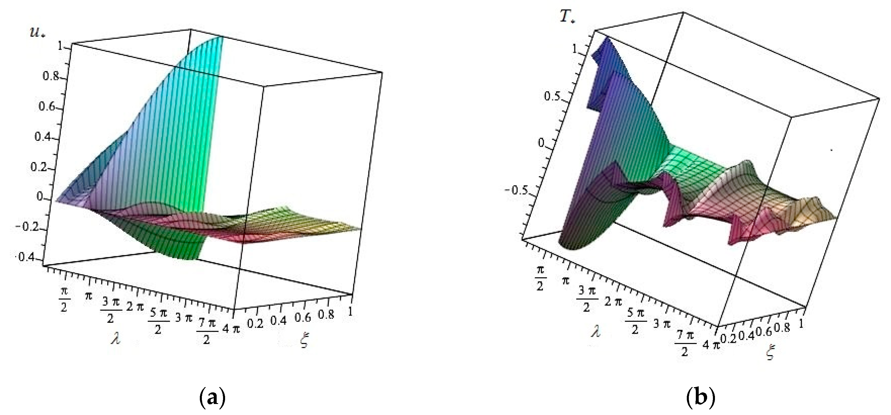
The results of the passive damping of a longitudinally polarized beam with a large number of electrodes are shown in Figure 6. The graphs show the dependence of forces T * and displacements u * on the dimensionless frequency coordinate ξ and the dimensionless frequency parameter. The graphical representation of the solution shows that the amplitude of the desired quantities near the resonances is small.
The performed calculations confirm the possibility of passive damping of the longitudinal vibrations of the beam near resonant frequencies using the piezoelectric effect.
We are currently conducting further research on active and passive damping of vibrations using the piezoelectric effect.
Estimates of the effectiveness of active and passive vibration damping are completely different. In the case of active vibration damping, piezoelements work as actuators. As a rule, in modern works, the efficiency of active vibration damping is not calculated since this is a complex problem.
The efficiency of active vibration damping is usually determined as the electromechanical coupling coefficient (EMCC). The EMCC has nothing to do with passive vibration damping. The EMCC is an important characteristic of the performance of piezoceramic elements. The concept of the EMCC is as follows: the EMCC is the ratio of electrical (mechanical) energy stored in the volume of a piezoceramic body and capable of conversion into the total mechanical (electrical) energy supplied to the body. This determination is the most complete one, but it is difficult to understand what “capable of conversion” means. The electromechanical coupling coefficient depends on many parameters—the geometry of the structure, the properties of the materials from which this structure is made, mechanical and electrical load, boundary conditions, vibration frequency. For some parameter values, the EMCC may be zero. This means that the piezo actuator does not convert energy and active damping does not occur. In [18], it was shown that the EMCC ke is determined according to the following formula
k e = U ( d ) U ( sh ) U ( d )
where U(d) is the internal energy of the body when the electrodes are disconnected and U(sh) is the internal energy for short-circuit electrodes. Our earlier investigations [18] have shown that this formula is general and it is true for any static and dynamic state for any electroelastic structure. Our previous published results will make it possible to correctly calculate the EMCC.

5. Conclusions

The studies performed have shown that the efficiency of vibration damping depends significantly on the direction of pre-polarization of the piezoceramic layers and on the number and location of its electrodes.
To dampen longitudinal vibrations of the beam near its resonant frequencies, we used piezoelectric layers on the faces of the beam. Since the properties of a piezoelectric material significantly depend on the direction of its pre-polarization, we considered different directions of pre-polarization—transverse along the x3 axis (Figure 1 and Figure 2) and longitudinal along the x1 axis (Figure 4). In addition, the location of the electrodes plays an important role in our study. In order to evaluate the vibration damping ability of the new method, we introduced the concept of damping efficiency. According to the definition, the damping efficiency is equal to the ratio of the absolute value of the difference of resonant frequencies, with the same numbers, for the beam with disconnected and short-circuited electrodes, respectively, as the resonant frequencies of the beam with short-circuited electrodes. Our research has shown that damping vibrations near the resonant frequencies of a beam with layers of piezoelectric material with transverse pre-polarization completely covered with electrodes (Figure 1) has low efficiency, which decreases with the increasing number of the resonant frequencies (Table 1). It is shown that if a large number of split electrodes are used for the same composite beam (Figure 2), then the damping efficiency remains small and is of the same order of magnitude for all resonant frequencies (Table 3). The highest damping efficiency was obtained when using piezoceramics with longitudinal pre-polarization with a large number of electrodes (Figure 4, Table 4). It is piezoceramics with longitudinal pre-polarization with a large number of electrodes that we recommend using to dampen beam vibrations near its resonant frequencies.
In the case of using piezoceramics with transverse pre-polarization of the beam, the face surfaces of which are covered with continuous electrodes (Table 1), the efficiency of damping is low. This is explained by:
(1)
the direction of polarization is orthogonal to the direction of longitudinal vibrations, and the main role in damping vibrations is played by that part of the electroelastic state, which is a consequence of the Poisson effect and operates in the longitudinal direction;
(2)
the use of continuous electrodes makes it possible to dampen vibrations only at the first resonant frequency.
To control the process of closing and opening electrodes, dynamic strain sensors (for example, piezoelectric sensors [19,20]) and a special program that processes sensor readings should be used. As the beam vibration frequency approaches the resonant frequency, the rate of change in deformations increases sharply. At this point, the program should provide a change in the electrical conditions on the electrodes.
The advantages of using the piezoelectric effect for passive damping of vibrations at resonances consist in its simplicity—the absence of the need for inertial operation of the vibration damper, the same intensity of damping at all resonant frequencies, as well as the stability of the properties of the piezoelectric damper material in wide temperature and time ranges and its low cost.

Author Contributions

All authors have contributed equally to the manuscript. All authors have read and agreed to the published version of the manuscript.

Funding

This research was supported by the Ministry of Science and Higher Education of the Russian Federation (project No. FSWG-2023-0004, «A system of territorial seismic protection of critical infrastructure facilities based on granular metamaterials with the properties of wide-range phonon crystals»).

Data Availability Statement

Not applicable.

Conflicts of Interest

The authors declare no conflict of interest.

References

  1. Preumont, A.; Seto, K. Vibration Control of Active Structures; John Wiley & Sons: Hoboken, NJ, USA, 2008; 295p. [Google Scholar]
  2. Salu, R.; Gokul, P.V.; James, S.C. Active Vibration Control of Laminated Composite Thin Plates Using a Smart Material. Int. J. Eng. Res. Technol. (IJERT) 2023, 11, 2278–0181. [Google Scholar]
  3. Inmah, D.J. Vibration with Control; Wiley Online Books; John Wiley & Sons: Hoboken, NJ, USA, 2017; ISBN 9781119375081. [Google Scholar]
  4. Kwak, M.K. Dynamic Modeling and Active Vibration Control of Structures; Springer: Dordrecht, The Netherlands, 2021; 371p. [Google Scholar]
  5. He, W.; Liu, J. Active Vibration Control and Stability Analysis of Flexible Beam Systems; Springer: Berlin/Heidelberg, Germany, 2019; 212p. [Google Scholar]
  6. Majeed, W.I.; Al-Samarraie, S.A.; Al-Saior, M.M. Vibration Control Analysis of a Smart Flexible Cantilever Beam Using Smart Material. J. Eng. 2023, 19, 82–95. [Google Scholar] [CrossRef]
  7. Liu, Z.; Chen, L.; Sun, L.; Zhao, L.; Cui, W.; Guan, H. Multimode damping optimization of a long-span suspension bridge with damped outriggers for suppressing vortex-induced vibrations. Eng. Struct. 2023, 286, 115959. [Google Scholar] [CrossRef]
  8. Isić, S.; Mehremić, S.; Karabegović, I.; Husak, E. Systems for Passive and Active Vibration Damping. In New Technologies, Development and Application II. NT 2019; Karabegović, I., Ed.; Lecture Notes in Networks and Systems; Springer: Cham, Switzerland, 2020; Volume 76. [Google Scholar] [CrossRef]
  9. Xiong, F.; Li, Y.; Wang, C. Experiment and analysis of active vibration isolation system based on rigid pedestal using SDOF actuator. J. Vibroeng. 2022, 24, 1072–1081. [Google Scholar] [CrossRef]
  10. Fujino, Y.; Siringoringo, D.M.; Ikeda, Y.; Nagayama, T.; Mizutani, T. Research and Implementations of Structural Monitoring for Bridges and Buildings in Japan. Engineering 2019, 5, 1093–1119. [Google Scholar] [CrossRef]
  11. Sidorov, V.N.; Badina, E.S. Finite-element modeling of vibrations of composite beams taking into account the damping of the non-local in time. Mech. Compos. Mater. Struct. 2021, 27, 65–72. [Google Scholar]
  12. Enríquez-Zárate, J.; Abundis-Fong, H.F.; Velázquez, R.; Gutiérrez, S. Passive vibration control in a civil structure: Experimental results. Meas. Control 2019, 52, 938–946. [Google Scholar] [CrossRef]
  13. Shen, R.; Qian, X.; Zhou, J.; Lee, C.L. Characteristics of passive vibration control for exponential non-viscous damping system: Vibration isolator and absorber. J. Vib. Control. 2022, 1, 10775463221130925. [Google Scholar] [CrossRef]
  14. Rogacheva, N.N. Passive Vibration Suppression of Structures in the Vicinity of Natural Frequencies Using Piezoeffect. Int. J. Comput. Civ. Struct. Eng. 2019, 15, 125–134. [Google Scholar] [CrossRef]
  15. Rogacheva, N.N. The dynamic behaviour of piezoelectric laminated bars. J. Appl. Math. Mech. 2007, 71, 494–510. [Google Scholar] [CrossRef]
  16. Berlincourt, D.A.; Curran, D.R.; Jaffe, H. Piezoelectric and Piezomagnetic Materials and Their Function in Transducers; Mason, W.P., Ed.; Physical Acoustics; Academic Press: New York, NY, USA, 1964; Volume 1A, pp. 169–270. [Google Scholar]
  17. CTS Product Catalogue. Available online: https://www.ferropermpiezoceramics.com/ (accessed on 25 June 2023).
  18. Chou, C.C.; Rogacheva, N.N.; Chang, S.H. Analysis of methods for determining electromechanical coupling-coefficients of piezoelectric elements. IEEE Trans. Ultrason. Ferroelectr. Freq. Control 1995, 42, 630–640. [Google Scholar]
  19. Werner, J.M.; Engelmann, M.; Schmidt, M.; Titsch, C.; Dix, M.; Drossel, W.G. Comparison of Structural Integrated Piezoceramics, Piezoelectric Patches and Strain Gauges for Condition Monitoring. Sensors 2022, 22, 8847. [Google Scholar] [CrossRef] [PubMed]
  20. Kim, K.; Kim, J.; Jiang, X.; Kim, T. Static Force Measurement Using Piezoelectric Sensors. J. Sens. 2021, 2021, 6664200. [Google Scholar] [CrossRef]
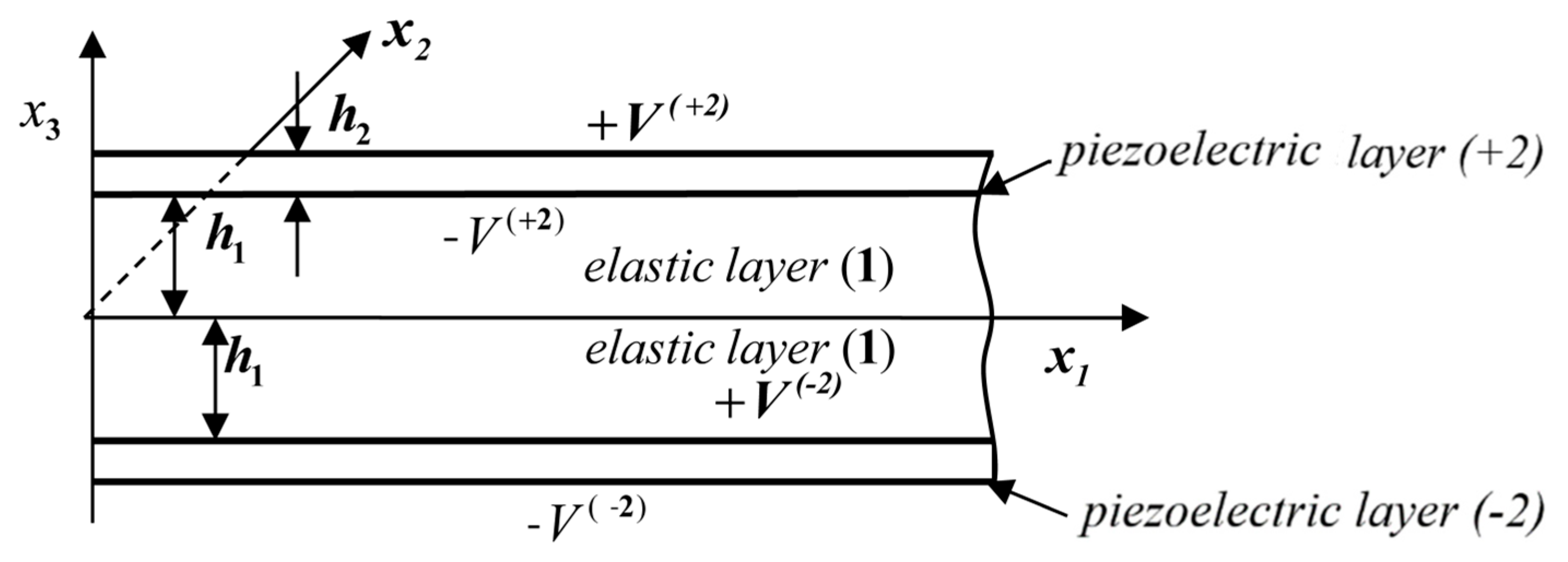
Figure 1. Schematic representation of the structure of the layered beam with continuous electrodes.
Axioms 12 00981 g001
Figure 2. Schematic representation of the structure of the layered beam with many split electrodes.
Axioms 12 00981 g002
Figure 3. (a) Force T * (x1 = 0) for a beam with short-circuited electrodes as a function of a dimensionless frequency parameter; (b) force T * (x1 = 0) for a beam with disconnected electrodes as a function of a dimensionless frequency parameter; (c) dependence of the force T * (x1 = 0) on the dimensionless frequency parameter as a result of vibration damping in the vicinity of resonances; (d) dependence of the displacement u * (x1 = l) on the free edge of the beam on the dimensionless frequency parameter as a result of vibration damping in the vicinity of resonances.
Axioms 12 00981 g003
Figure 4. Schematic representation of the structure of the layered beam with composite piezoelectric layers.
Axioms 12 00981 g004
Figure 5. (a) Force T * (x1 = 0) for a beam with short-circuited electrodes as a function of a dimensionless frequency parameter; (b) force T * (x1 = 0) for a beam with disconnected electrodes as a function of a dimensionless frequency parameter; (c) dependence of the force T * (x1 = 0) on the dimensionless frequency parameter as a result of vibration damping in the vicinity of resonances; (d) dependence of the displacement u * (x1 = l) on the free edge of the beam on the dimensionless frequency parameter as a result of vibration damping in the vicinity of resonant frequencies.
Axioms 12 00981 g005
Figure 6. (a) Dependence of displacements u * on variable ξ and a dimensionless frequency parameter; (b) dependence of force T * on a variable ξ and a dimensionless frequency parameter.
Axioms 12 00981 g006
Table 1. Values of the dimensionless frequency parameter at resonances of a beam with continuous electrodes and the efficiency of vibration damping for the first five resonant frequencies.
n12345
λ ( sh ) 1.57084.71247.854010.995614.1372
λ ( d ) 1.66484.74547.873811.009814.1482
f0.05980.00700.00250.00130.0008
Table 2. Values of the dimensionless frequency parameter at resonances of a beam with a pair of electrodes on each surface and the efficiency of vibration damping at the first five resonances.
n12345
λ ( sh ) 1.57084.71247.854010.995614.1372
λ ( d ) 1.62814.82057.922911.003914.1437
f0.03650.02290.00880.00080.0005
Table 3. Values of the dimensionless frequency parameter at resonances of a beam with a large number of split electrodes and the efficiency of vibration damping for the first five resonant frequencies.
n12345
λ ( sh ) 1.57084.71247.854010.995614.1372
λ ( d ) 1.68975.06918.448511.828015.2074
f0.07040.07570.07570.07570.0757
Table 4. Values of the dimensionless frequency parameter at beam resonant frequencies and vibration damping efficiency for the first five resonant frequencies.
n12345
λ ( sh ) 1.57084.71247.854010.995614.1372
λ ( d ) 2.36697.100611.834416.568221.3019
f0.50680.50680.50680.50680.5068
Disclaimer/Publisher’s Note: The statements, opinions and data contained in all publications are solely those of the individual author(s) and contributor(s) and not of MDPI and/or the editor(s). MDPI and/or the editor(s) disclaim responsibility for any injury to people or property resulting from any ideas, methods, instructions or products referred to in the content.