Development of a Simulator for Random and Non-Random Breakage of Particles and Liberation of Grains Based on Voronoi Tessellation


Abstract
:1. Introduction
2. Materials and Methods
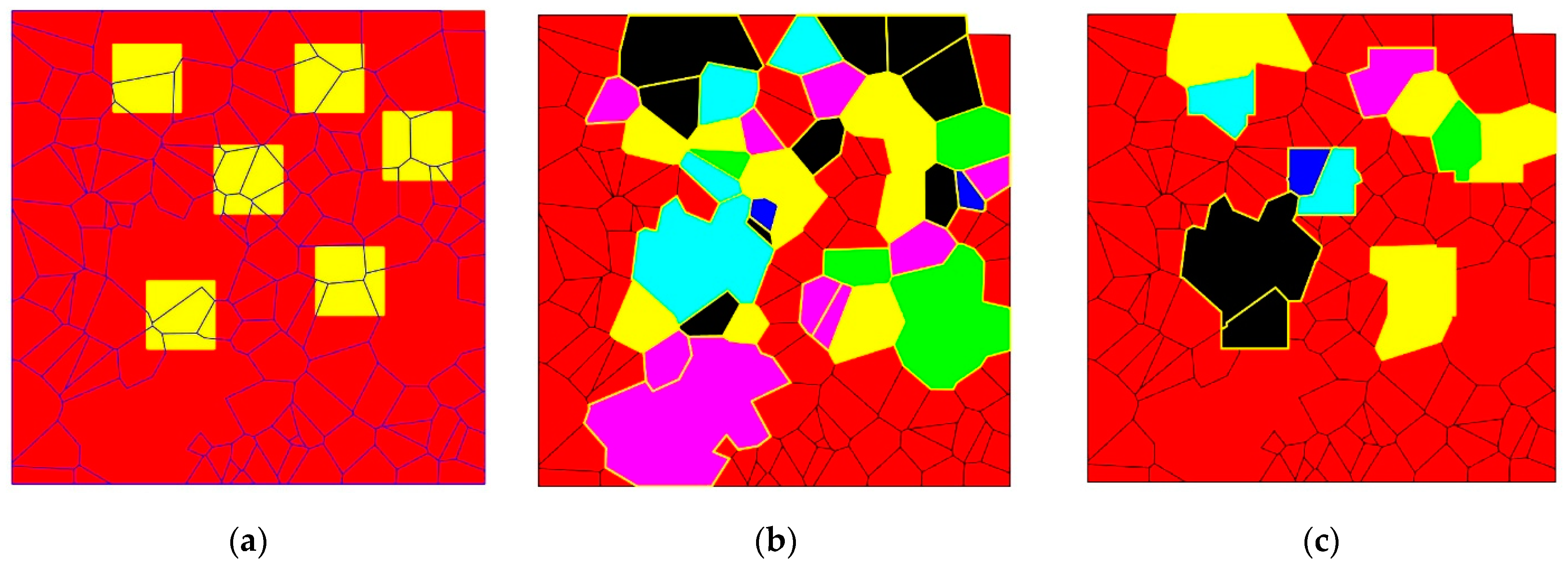
2.1. Simulation
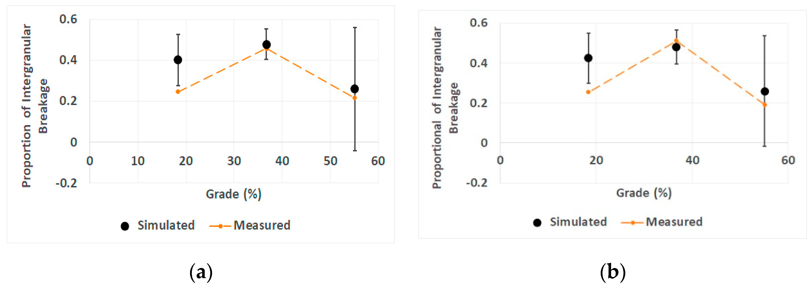
2.2. Validation
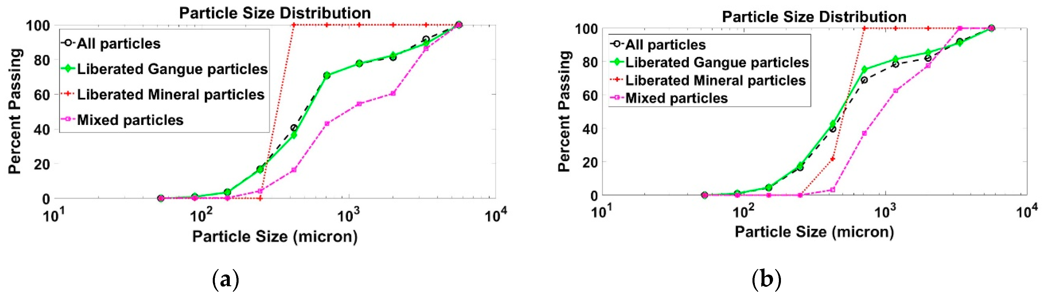
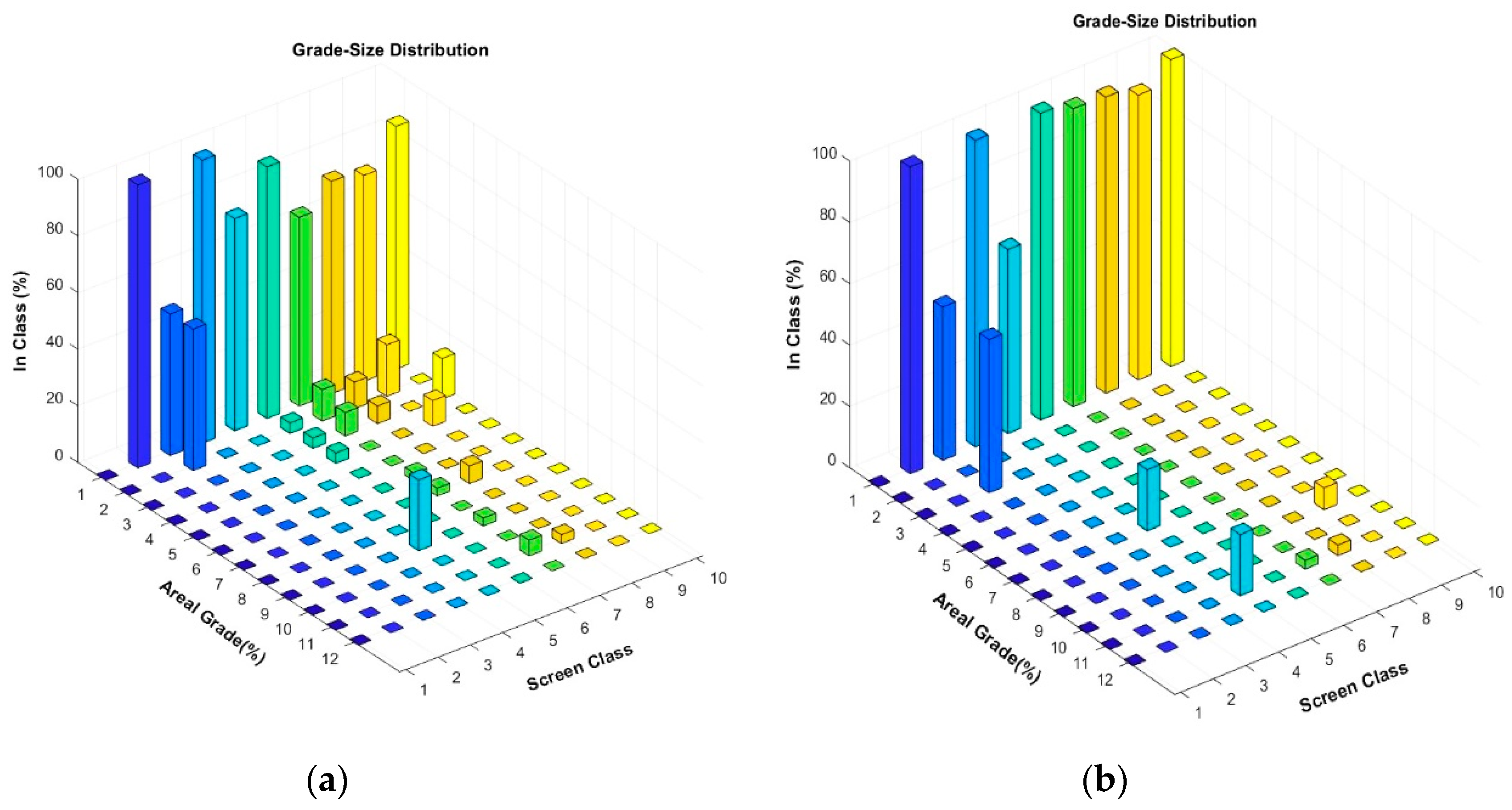
3. Results
4. Discussion
5. Conclusions
Author Contributions
Funding
Acknowledgments
Conflicts of Interest
References
- Leißner, T.M.; Mütze, T.; Bachmann, K.; Rode, S.; Gutzmer, J.; Peuker, U.A. Evaluation of mineral processing by assessment of liberation and upgrading. Miner. Eng. 2013, 53, 171–173. [Google Scholar] [CrossRef]
- Bole, J.; Lin, C.L.; Miller, J.D. Experimental verification of the PARGEN simulator for liberation analysis. Int. J. Miner. Process. 1993, 37, 209–221. [Google Scholar] [CrossRef]
- Herbst, J.A.; Rajamani, K.; Lin, C.L.; Miller, J.D. Development of a multicomponent-multisize liberation model. Miner. Eng. 1988, 1, 97–111. [Google Scholar] [CrossRef]
- Gay, S. A liberation model for comminution based on probability theory. Miner. Eng. 2004, 17, 525–534. [Google Scholar] [CrossRef]
- Wills, B.; Atkinson, K. Some observations on the fracture and liberation of mineral assemblies. Miner. Eng. 1993, 6, 697–706. [Google Scholar] [CrossRef]
- Hsih, C.S.; Wen, S.B. An extension of Gaudin’s liberation model for quantitatively representing the effect of detachment in liberation. Int. J. Miner. Process. 1994, 42, 15–35. [Google Scholar] [CrossRef]
- King, R.P. Modeling and Simulation of Mineral Processing Systems; Butterworth-Heinemann: Oxford, UK, 2001. [Google Scholar]
- Gaudin, A. Principles of Mineral Dressing; McGraw-Hill: New York, NY, USA, 1939. [Google Scholar]
- Klimpel, R.R.; Austin, L.G. A Preliminary Model of Liberation from a Binary System. Powder Technol. 1983, 34, 121–130. [Google Scholar] [CrossRef]
- Wiegel, R.L. A random model for mineral liberation by size reduction. Trans. AIME 1967, 238, 179–189. [Google Scholar]
- King, R.P.; Schneider, C.L. Mineral liberation and the batch communition equation. Miner. Eng. 1998, 11, 1143–1160. [Google Scholar] [CrossRef]
- Mariano, R.; Evans, C.; Manlapig, E. Definition of random and non-random breakage in mineral liberation-A review. Miner. Eng. 2016, 94, 51–60. [Google Scholar] [CrossRef]
- Sutherland, D.; Fandrich, R. Selective fracture and liberation of minerals. In Proceedings of the Chemeca 96: Excellence in Chemical Engineering: 24th Australian and New Zealand Chemical Engineering Conference and Exhibition, Sydney, Australia, 30 September–2 October 1996; pp. 83–88. [Google Scholar]
- Wills, B.A.; Finch, J. Wills’ Mineral Processing Technology: An Introduction to the Practical Aspects of Ore Treatment and Mineral Recovery; Butterworth-Heinemann: Oxford, UK, 2015. [Google Scholar]
- Bérubé, M.A.; Marchand, J.C. Evolution of the mineral liberation characteristics of an iron ore undergoing grinding. Int. J. Miner. Process. 1984, 13, 223–237. [Google Scholar] [CrossRef]
- Revnivtsev, V.K.; Ye, P.; Finkelstein, G.A.; Zarogatsky, L.P.; Ivanov, N.A.; Blekhman, I.I.; Ivanov, B.G. Selective liberation of minerals in inertial cone crushers. Powder Technol. 1984, 38, 195–203. [Google Scholar] [CrossRef]
- Austin, L.G.; Luckie, P.T. The problems of quantifying mineral liberation: A review. Part. Part. Syst. Charact. 1988, 5, 122–129. [Google Scholar] [CrossRef]
- Laslett, G.; Sutherland, D.; Gottlieb, P.; Allen, N. Graphical assessment of a random breakage model for mineral liberation. Powder Technol. 1990, 60, 83–97. [Google Scholar] [CrossRef]
- Choi, W.; Adel, G.; Yoon, R. Liberation modeling using automated image analysis. Int. J. Miner. Process. 1988, 22, 59–73. [Google Scholar] [CrossRef]
- Fandrich, R.G.; Bearman, R.A.; Boland, J.; Lim, W. Mineral liberation by particle bed breakage. Miner. Eng. 1997, 10, 175–187. [Google Scholar] [CrossRef]
- Garcia, D.; Lin, C.L.; Miller, J.D. Quantitative analysis of grain boundary fracture in the breakage of single multiphase particles using X-ray microtomography procedures. Miner. Eng. 2009, 22, 236–243. [Google Scholar] [CrossRef]
- Xu, W.; Dhawan, N.; Lin, C.L.; Miller, J.D. Further study of grain boundary fracture in the breakage of single multiphase particles using X-ray microtomography procedures. Miner. Eng. 2013, 46, 89–94. [Google Scholar] [CrossRef]
- King, R.P. Calculation of the liberation spectrum in products produced in continuous milling circuits. In Proceedings of the 7th European Symposium on Comminution, Ljubljana, Slovenia, 12–14 June 1990; pp. 429–444. [Google Scholar]
- Little, L.; Mainza, A.N.; Becker, M.; Wiese, J.G. Using mineralogical and particle shape analysis to investigate enhanced mineral liberation through phase boundary fracture. Powder Technol. 2016, 301, 794–804. [Google Scholar] [CrossRef]
- Leißner, T.; Hoang, D.; Rudolph, M.; Heinig, T.; Bachmann, K.; Gutzmer, J.; Schubert, H.; Peuker, U. A mineral liberation study of grain boundary fracture based on measurements of the surface exposure after milling. Int. J. Miner. Process. 2016, 156, 3–13. [Google Scholar] [CrossRef]
- Tanemura, M.; Ogawa, T.; Ogita, N. A new algorithm for three-dimensional voronoi tessellation. J. Comput. Phys. 1983, 51, 191–207. [Google Scholar] [CrossRef]
- Machado Leite, M.R. Liberation by size reduction. Consequences and improvements on flotation kinetics. In Innovations in Flotation Technology; Springer: Dordrecht, The Netherlands, 1992; pp. 149–170. [Google Scholar]
- Vassiliev, P.V.; Ledoux, H.; Gold, C. Modeling Ore Texture and Mineral Liberation Using 3D Voronoi Diagrams. In Proceedings of the International Conference “Numerical Geometry, Grid Generation and High Performance Computing”, Moscow, Russia, 10–13 June 2008; pp. 10–13. [Google Scholar]
- Khalesi, M.R.; Bazin, C.; Hodouin, D.; Bellec, S. A grinding-liberation model for the size reduction of gold ores. In Proceedings of the World Gold Conference, Johannesburg, South Africa, 26–30 October 2009. [Google Scholar]
- Khalesi, M.R.; Bazin, C.; Hodouin, D.; Bellec, S. Simulation of gold grain exposure of ground ore using Voronoi tessellation. IFAC Proc. Vol. 2009, 42, 43–48. [Google Scholar] [CrossRef]
- Rozenbaum, O.; Machault, J.; Le Trong, E.; Tankeu, Y.G.N.; Barbanson, L. Ore fragmentation modelling for the evaluation of the liberation mesh size. In Proceedings of the 13th SGA Biennal Meeting, Nancy, France, 24–27 August 2015; pp. 1447–1450. [Google Scholar]
- Van der Wielen, K.P.; Rollinson, G. Texture-based analysis of liberation behaviour using Voronoi tessellations. Miner. Eng. 2016, 89, 93–107. [Google Scholar] [CrossRef]
- Ueda, T.; Oki, T.; Koyanaka, S. A general quantification method for addressing stereological bias in mineral liberation assessment in terms of volume fraction and size of mineral phase. Miner. Eng. 2018, 119, 156–165. [Google Scholar] [CrossRef]
- Mirzaei, Z.S.; Khalesi, M.R. Liberation Analysis Using a New Simulator of Random and non-Random Breakage. In Proceedings of the 16th International Mineral Processing Symposium (IMPS 2018), Antalya, Turkey, 23–25 October 2018. [Google Scholar]
- Johnston, I.W.; Choi, S.K. Synthetic soft rock for laboratory model studies. Int. J. Rock Mech. Min. Sci. Geomech. Abstr. 1986, 23, 251–263. [Google Scholar] [CrossRef]
- Kiss, L.; Schönert, K. Liberation of two-component material by single particle compression and impact crushing. Aufbereitungs-Technick 1980, 5, 223–230. [Google Scholar]
- Woollacott, L.C.; Valenta, M. Use of synthetic ore particles to test a transformation function in liberation analysis. Miner. Eng. 1996, 9, 1017–1032. [Google Scholar] [CrossRef]
- Ueda, T.; Oki, T.; Koyanaka, S. Experimental analysis of mineral liberation and stereological bias based on X-ray computed tomography and artificial binary particles. Adv. Powder Technol. 2018, 29, 462–470. [Google Scholar] [CrossRef]
- Rezvani, A.; Khalesi, M.R.; Mirzaei, Z.S.; Albijanic, B. A simple method for determination of liberation spectrum of high-grade ores by images analysis of crushed particles. Adv. Powder Technol. 2019. submitted. [Google Scholar]
- Ueda, T.; Oki, T.; Koyanaka, S. Statistical effect of sampling particle number on mineral liberation assessment. Miner. Eng. 2016, 98, 204–212. [Google Scholar] [CrossRef]
- Ueda, T.; Oki, T.; Koyanaka, S. Numerical analysis of the general characteristics of stereological bias in surface liberation assessment of ore particles. Adv. Powder Technol. 2018, 29, 3327–3335. [Google Scholar] [CrossRef]


© 2019 by the authors. Licensee MDPI, Basel, Switzerland. This article is an open access article distributed under the terms and conditions of the Creative Commons Attribution (CC BY) license (http://creativecommons.org/licenses/by/4.0/).
Share and Cite
Mirzaei, Z.S.; Khalesi, M.R. Development of a Simulator for Random and Non-Random Breakage of Particles and Liberation of Grains Based on Voronoi Tessellation. Minerals 2019, 9, 341. https://doi.org/10.3390/min9060341
Mirzaei ZS, Khalesi MR. Development of a Simulator for Random and Non-Random Breakage of Particles and Liberation of Grains Based on Voronoi Tessellation. Minerals. 2019; 9(6):341. https://doi.org/10.3390/min9060341
Chicago/Turabian StyleMirzaei, Zeinab Sadat, and Mohammad Reza Khalesi. 2019. "Development of a Simulator for Random and Non-Random Breakage of Particles and Liberation of Grains Based on Voronoi Tessellation" Minerals 9, no. 6: 341. https://doi.org/10.3390/min9060341
APA StyleMirzaei, Z. S., & Khalesi, M. R. (2019). Development of a Simulator for Random and Non-Random Breakage of Particles and Liberation of Grains Based on Voronoi Tessellation. Minerals, 9(6), 341. https://doi.org/10.3390/min9060341