Article

Swell–Shrink Behavior of Rubberized Expansive Clays during Alternate Wetting and Drying

1
School of Civil, Environmental and Mining Engineering, The University of Adelaide, Adelaide, SA 5005, Australia
2
Department of Infrastructure Engineering, The University of Melbourne, Parkville, VIC 3010, Australia
3
School of Engineering and Technology, Central Queensland University, Melbourne, VIC 3000, Australia
4
Department of Civil Engineering, The University of Ottawa, Ottawa, ON K1N 6N5, Canada
*
Authors to whom correspondence should be addressed.
Minerals 2019, 9(4), 224; https://doi.org/10.3390/min9040224
Submission received: 18 March 2019 / Revised: 31 March 2019 / Accepted: 6 April 2019 / Published: 9 April 2019

Abstract

:
The present study examines rubber’s capacity of improving the swell–shrink potential of expansive clays. Two rubber types of fine and coarse categories with different geometrical features were considered. The test program consisted of standard Proctor compaction and cyclic wetting–drying tests. Scanning electron microscopy (SEM) analysis was also performed to identify the soil–rubber amending mechanisms, and to observe the evolution of fabric in response to alternate wetting and drying. Cyclic wetting–drying led to the reconstruction of the soil/soil–rubber microstructure by way of inducing aggregation and cementation of the soil grains. The greater the number of applied cycles, the lower the swell–shrink features, following a monotonically decreasing trend, with the rubberized blends holding a notable advantage over the virgin soil. The tendency for reduction, however, was in favor of a larger rubber size, and more importantly the rubber’s elongated form factor; thus, predicating a rubber size/shape-dependent amending mechanism. The soil–rubber amending mechanisms were discussed in three aspects—increase in non-expansive content, frictional resistance generated as a result of soil–rubber contact, and mechanical interlocking of rubber particles and soil grains. The swell–shrink patterns/paths indicated an expansive accumulated deformation for the virgin soil, whereas the rubberized blends manifested a relatively neutral deformational state, thereby corroborating the rubber’s capacity to counteract the heave and/or settlement incurred by alternate wetting and drying.

1. Introduction

The design and implementation of geostructures often necessitate incorporating expansive clays, with high moisture susceptibility and low bearing capacity, into the construction. A notable fraction of the expansive clay is constituted of active smectite minerals, such as montmorillonite, which exhibit significant swell–shrink volume changes, as well as desiccation-induced cracking, upon the addition or removal of water [1]. Such actions bring forth major instability concerns to the overlying structures, and thus demand engineering solutions to alleviate the associated socio-economic impacts on human life [2].
Common solutions to counteract the adversities associated with expansive clays include soil replacement and/or soil stabilization. The former involves substituting a portion of the low-graded expansive clay with suitable quarried materials possessing minimal swell–shrink tendency. The latter, soil stabilization, refers to any chemical, mechanical, or combined chemical-mechanical practice of altering the expansive clay fabric to meet the intended engineering criteria [3]. The chemical stabilization scheme makes use of chemical binders (e.g., cements, limes, fly ashes, slags, polymers, resins and sulfonated oils), which initiate a series of short- and long-term chemical reactions in the soil–water medium, thereby amending the soil fabric into a coherent matrix of improved mechanical performance [4,5,6,7,8,9]. Mechanical stabilization often involves the placement of random or systematically engineered reinforcements in the soil regime (e.g., fibers and geogrids), thereby engendering a spatial three-dimensional reinforcement network in favor of weaving/interlocking the soil grains into a unitary mass of restricted swell–shrink movements [4,10,11,12,13,14]. Though proven effective, conventional stabilization agents often suffer from sustainability issues, attributed to high manufacturing and/or transportation costs, as well as environmental concerns due to greenhouse gas emissions.
A sustainable soil stabilization scheme can be characterized as one that maintains a perfect balance between infrastructure performance and the social, economic, and ecological processes required to maintain human equity, diversity, and the functionality of natural systems [9]. The transition towards sustainable stabilization necessitates reusing solid wastes and/or industrial by-products as part of the infrastructure system, and more specifically as replacements for conventional stabilization agents. Promising replacements, as reported in the research literature, consist of recycled tire rubbers, waste textiles, demolition wastes, and silicate/calcium geopolymers [15,16,17,18,19,20]. Among others, discarded tires account for the largest volume of disposals throughout the world, and thus demand further attention. The use of recycled tire rubbers in geotechnical practice dates back to the early 1990s, where theoretical concepts governing the performance of soil–rubber blends were put into perspective. It was noted that similar to fiber-reinforced soils, the rubber assemblage randomly distributes in the soil regime, and where optimized in content and geometry, alters the soil fabric by amending the bonding along the interface/contact between the soil and the reinforcement, thereby enhancing the integrity and stability of the low-graded host soil [21,22,23,24,25]. The literature from this era, however, was mainly focused on coarse-grained soils; as such, rubber’s capacity of improving the inferior engineering characteristics of expansive clays remained rather vague. Table 1 presents a summary of recent contributions addressing the swelling behavior of rubber mixed expansive clays [2,26,27,28,29,30,31,32,33,34,35,36,37,38,39].
Based on these studies, the soil–rubber amending mechanisms can be attributed to the rubber content, with higher rubber inclusions yielding a more pronounced reduction in the swelling capacity. Moreover, the rubber’s geometrical features, mainly defined in terms of the rubber’s mean particle size, may also portray an equally important role; this aspect still remains a rather limited area of study and hence requires further examination.
Seasonal fluctuations—defined as alternate periods of rainfall and drought (or cyclic wetting–drying)—lead to the reconstruction of the soil microstructure, which in turn alters the volume change behavior of the expansive clay [40]. Consequently, arriving at reliable solutions capable of counteracting the adversities associated with expansive clays demands a further examination of the introduced stabilization scheme under the cyclic wetting–drying action. The cyclic wetting–drying behavior of natural expansive clays has been well documented in the literature [41,42,43,44,45,46,47,48]. In comparison, the number of documented studies addressing the cyclic wetting–drying behavior of stabilized expansive clays is limited, most of which have been carried out in the context of chemical stabilization by means of cementitious and/or polymeric binders [6,7,49,50,51,52,53]. To the authors’ knowledge, however, the cyclic wetting–drying behavior of rubber mixed expansive clays remains undetermined.
To accommodate a further step towards sustainability, the present study intends to examine rubber’s capacity of improving the inferior engineering characteristics of expansive clays. Two rubber types of fine and coarse categories with different geometrical features were considered. The experimental program consisted of standard Proctor compaction and cyclic wetting–drying tests. Scanning electron microscopy (SEM) analysis was also introduced to identify the soil–rubber amending mechanisms, and to observe the evolution of fabric in response to alternate wetting and drying.

2. Materials

2.1. Expansive Clay

The soil used in this study was a mixture of 85% kaolinite and 15% sodium-activated bentonite by mass [39]. The physical and mechanical properties of the soil, determined as per relevant ASTM and Australian (AS) standards, are summarized in Table 2.
The conventional gradation analysis, carried out in accordance with ASTM D422–07, indicated a clay fraction (<2 μm) of 52.80%, along with 46.16% silt (2–75 μm) and 1.04% fine sand (0.075–0.425 mm). The liquid limit and plasticity index were, respectively, measured as wL = 59.60% and IP = 32.32%, from which the soil was characterized as clay with high plasticity (CH) in accordance with the Unified Soil Classification System (USCS). The free swell ratio (FSR) was measured as 2.91, from which the soil was graded as highly expansive [55]. Other soil properties, as supplied by the manufacturer, included a neutral pH of 7.80, a specific surface area of 42.75 m2/g, and a cation exchange capacity of 21.65 meq/100 mL.

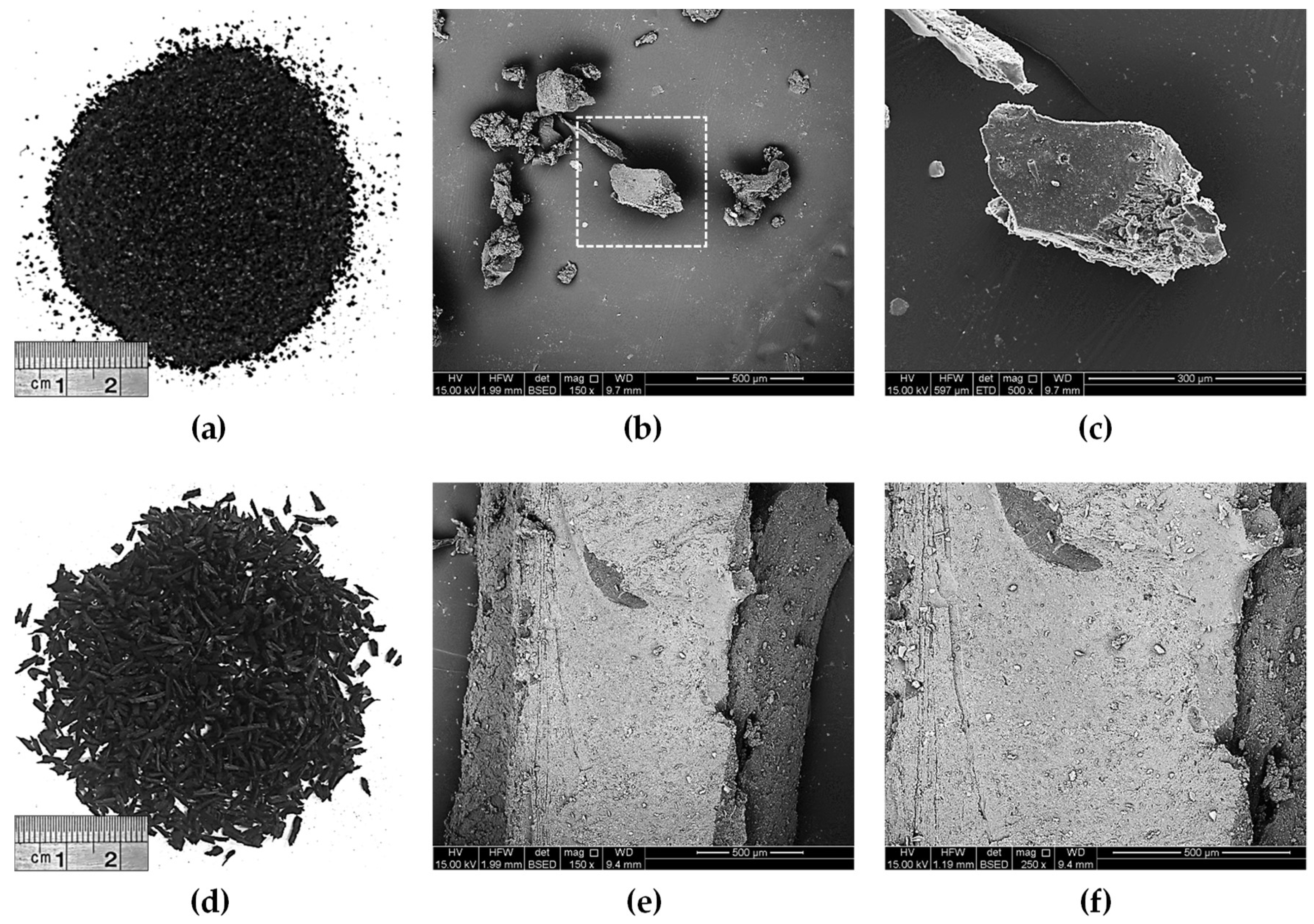
2.2. Recycled Tire Rubbers

Commercially available recycled tire rubbers of fine (RA) and coarse (RB) gradations were used for swell–shrink mitigation [39]. The physical properties and chemical composition of the rubbers, as supplied by the manufacturer, are presented in Table 3. The particles of RA were analogous in size to fine-medium sand (0.075–2 mm), whereas RB was graded into the medium-coarse sand category (0.425–4.75 mm). The coefficients of uniformity and curvature were measured as Cu = 2.81 and Cc = 1.20 for RA, and Cu = 1.56 and Cc = 1.04 for RB, from which both rubber types were characterized as poorly graded sand (SP) in accordance with the USCS criterion. The specific gravity (at 20 °C) for both rubber types was provided as Gsr = 1.09, which is in compliance with that reported in the literature (see Yadav and Tiwari [56] for details).
The SEM technique was used to observe the rubbers’ surface features, and the results are provided in Figure 1. The rubber particles are non-spherical and highly irregular in shape, with some cavities and microcracks propagated along the rubbers’ surface, thus predicating a rough surface texture. Such surface features may potentially engender a spatial three-dimensional reinforcement network in favor of weaving/interlocking the soil grains into a coherent matrix of enhanced mechanical performance [2,20,37].

3. Experimental Methodologies

Three mix designs, consisting of the virgin soil (C) and two rubberized blends (CRA and CRB), were considered for the experimental program. The choice of rubber content for the rubberized blends was selected as 10% (by mass of soil), which, as reported by the authors, was deemed as optimum to satisfy desirable improvements in the swell–shrink–consolidation capacity (without cyclic wetting–drying action), as well as the strength-related features [39]. The experimental program was carried out in two phases consisting of preliminary compaction studies and cyclic wetting–drying tests. SEM analysis was also introduced to complement the discussion on soil–rubber interactions during alternate wetting and drying.

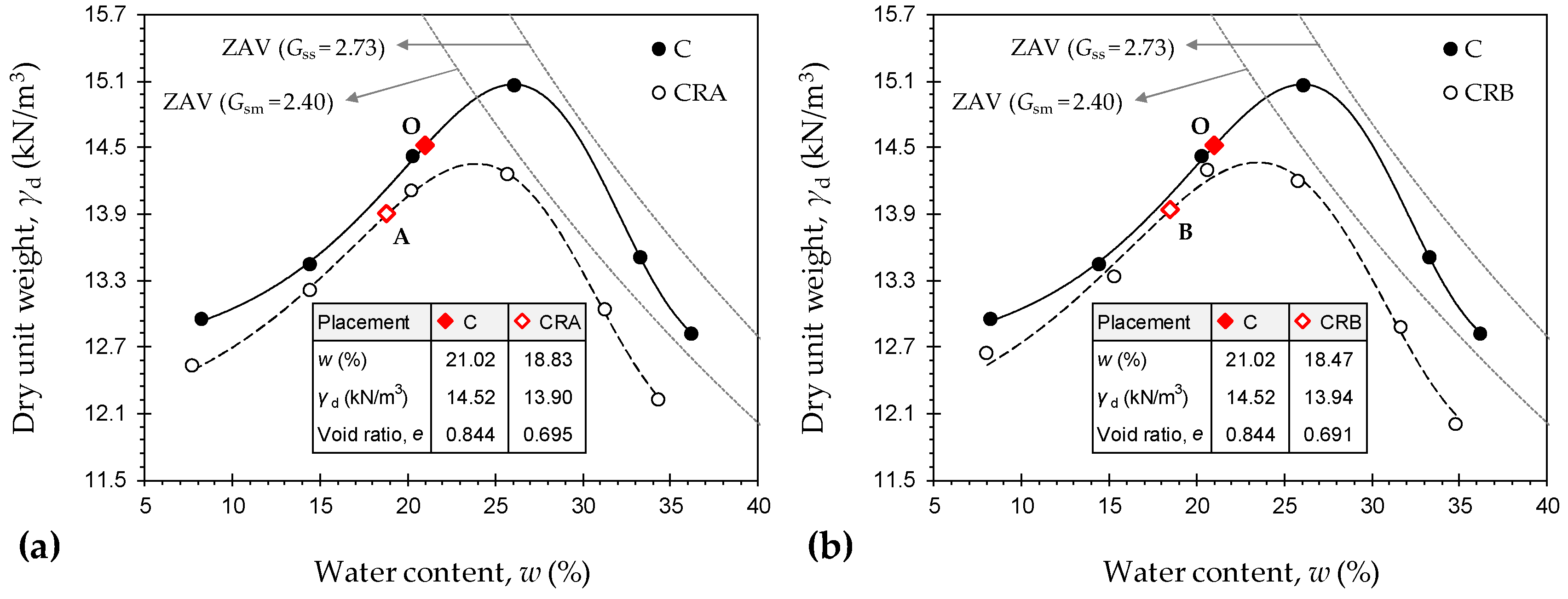
3.1. Compaction Studies and Sample Preparations

The three mix designs, namely, C, CRA, and CRB, were tested for standard Proctor compaction characteristics in accordance with ASTM D698–12, and the results are provided in Figure 2. The specific gravity of CRA and CRB was estimated using the weighted averaging technique [30], which this resulted in Gsm = 2.40 for both rubberized blends. As a result of rubber inclusion, the compaction locus experienced a notable downward-leftward translation over the γd:w space (i.e., where γd represents dry unit weight and w represents water content), indicating a notable reduction in both the maximum dry unit weight γdmax and the optimum water content wopt. The effect of rubber size, however, was found to be marginal. The virgin soil resulted in γdmax = 15.07 kN/m3 (wopt = 26.00%), whereas the inclusion of 10% RA and RB resulted in γdmax = 14.35 kN/m3 and 14.37 kN/m3 (wopt = 23.87% and 23.46%), respectively. Such trends can be attributed to the lower specific gravity, specific surface area, and water adsorption capacity (or hydrophobic nature) of the rubber particles compared with the soil grains [32,34].
Samples for the cyclic wetting–drying tests were prepared at their respective dry of optimum condition, defined as 5% less than the optimum water content and its corresponding dry unit weight—point “O” for C, point “A” for CRA, and point “B” for CRB, as outlined in Figure 2. The choice of dry of optimum was to account for the delay in compaction under field conditions. The virgin soil and the two rubberized blends were each statically compacted to the desired placement condition in the oedometer mold (measuring 50 mm in diameter and 20 mm in height), and were further subjected to cyclic wetting–drying tests (see Section 3.2). Supplementary details on the sample preparations, including soil–rubber mixing and static compaction, can be found in Soltani et al. [39].

3.2. Cyclic Wetting–Drying Test

The desired sample, namely, C, CRA, or CRB, was inundated with water and allowed to freely swell in a conventional oedometer setup under a low nominal overburden stress of 1 kPa, as per the ASTM D4546–14 standard. The incurred axial swelling strain was recorded (by a digital displacement transducer) during predefined time intervals to a point at which the ultimate swelling strain, denoted as swelling potential, could be achieved. Upon completion of the wetting process, reservoir water was drained through a drainage valve embedded within the oedometer cell. The oedometer cell, which houses the swollen sample, was then transferred to an oven where drying of the sample was attempted at a constant temperature of 40 °C. The incurred axial shrinkage strain was regularly monitored (by a dial displacement transducer) to a point at which the ultimate shrinkage strain, denoted as shrinkage potential, could be achieved. The combination of one wetting and the subsequent drying stage is designated as one wetting–drying cycle. For any given cycle, the swelling or shrinkage potential can be obtained as follows:
S P ( N ) S H P ( N ) = Δ H U ( N ) H o ( N 1 )     N = { 1 , 2 , 3 , }
where SP(N) is the swelling potential with respect to the Nth wetting cycle; SHP(N) is the shrinkage potential with respect to the Nth drying cycle; ΔHU(N) is the ultimate change in the sample’s thickness with respect to the Nth wetting or drying cycle; and Ho(N − 1) is the sample’s thickness prior to commencement of the Nth wetting or drying cycle.
The swelling and shrinkage potentials may either decrease or increase with an increase in the number of applied cycles; regardless of the observed trend, they attain equilibrium upon the completion of several cycles [43]. In the present study, the equilibrium condition was noted at the fourth cycle, and as such, only five wetting–drying cycles were implemented for the tested samples. The void ratio–water content relationship during shrinkage, denoted as the shrinkage curve, was also measured at the first and fifth drying cycles. For each mix design, a total of two duplicated samples were subjected to cyclic wetting–drying and dismantled upon completion of the first and fifth wetting stages. The swollen samples were then carefully removed from the oedometer cell and transferred to an oven where drying was attempted at a constant temperature of 40 °C. These samples were regularly tested for void ratio (as per ASTM D427–04) and water content (as per ASTM D2216–10) to a point at which the shrinkage process ceased.

3.3. Microstructure Analysis

Scanning electron microscopy (SEM) studies were carried out to observe the evolution of fabric in response to alternate wetting and drying. The Philips XL20 (Amsterdam, The Netherlands) scanning electron microscope, with a resolution of 4 μm and a maximum magnification ratio of 50,000×, was employed for SEM imaging. Two cases/samples were tested for each mix design: (i) prior to wetting–drying (or as-compacted); and (ii) after wetting–drying (or at the end of the fifth drying cycle). The desired samples were carefully fractured into small cubic-shaped pieces, measuring approximately 1 cm3 in volume, as suggested in the research literature [2,50], and were further scanned over various magnification ratios ranging from 150× to 20,000×.

4. Results and Discussion

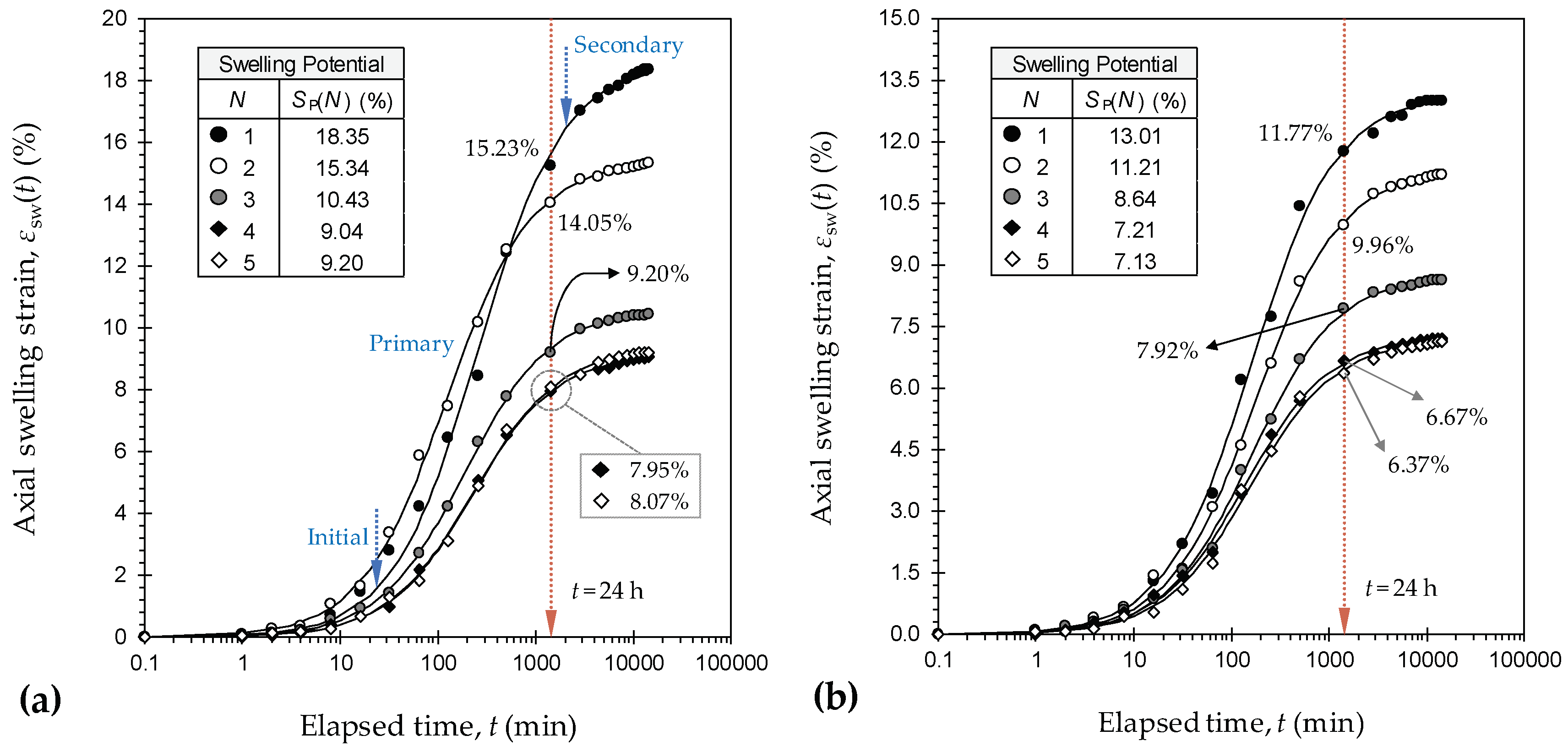
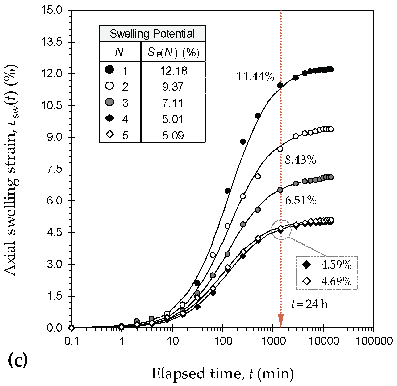
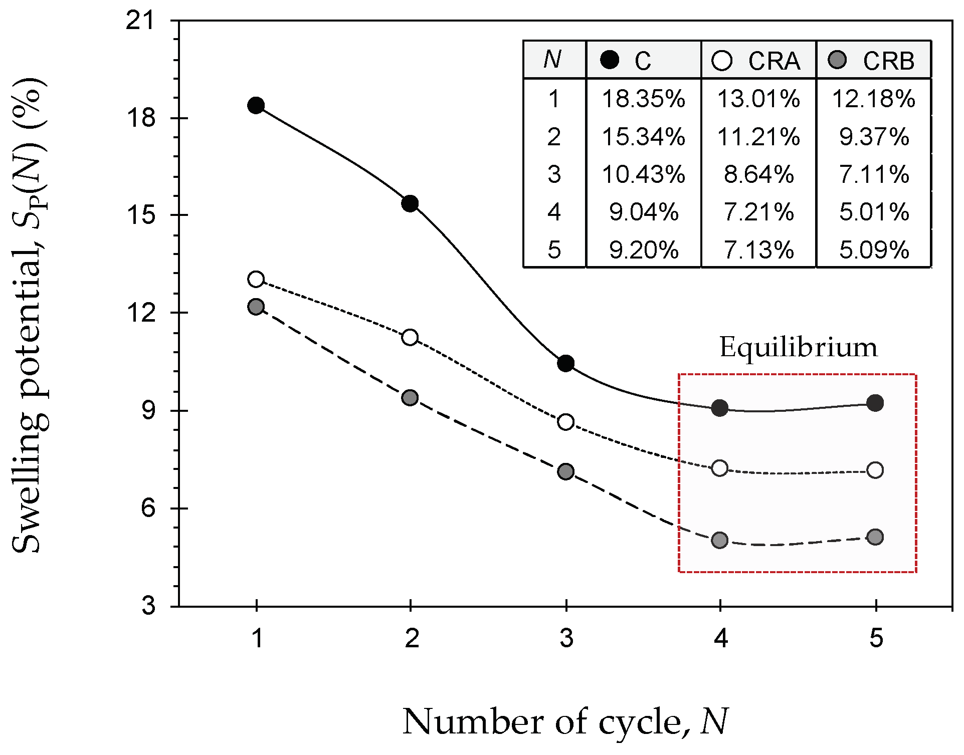
4.1. Swelling Characteristics

Swell–time curves for the samples C, CRA, and CRB during alternate wetting cycles are provided in Figure 3a–c, respectively. As a result of alternate wetting and drying, the swell–time locus encountered a major downward shift over the εsw:logt space (i.e., where εsw represents axial swelling strain and t represents elapsed time of swelling), indicating a significant reduction in the magnitude of the exhibited swelling strain during swell evolvement. At any given elapsed time of swelling, the greater the number of applied cycles N, the lower the swelling tendency, with both rubberized blends holding a notable advantage over the virgin soil. At t = 24 h, for instance, the virgin soil resulted in εsw = 15.23%, 14.05%, 9.20%, 7.95%, and 8.07% at N = 1–5 (see Figure 3a), whereas the inclusion of 10% RA resulted in lower values of 11.77%, 9.96%, 7.92%, 6.67%, and 6.37%, respectively (see Figure 3b). The same 10% inclusion of RB demonstrated a more pronounced decreasing trend, as the aforementioned values dropped to εsw = 11.44%, 8.43%, 6.51%, 4.59%, and 4.69% (at N = 1–5), respectively (see Figure 3c).
Figure 4 illustrates the variations of swelling potential SP against the number of applied cycles for the tested samples. The greater the number of applied cycles, the lower the swelling potential, following a monotonically decreasing trend with marginal variations beyond the equilibrium cycle (or N = 4). For any given cycle, the swelling potential can be orderly ranked as C > CRA > CRB, thus predicating a rubber size/shape-dependent amending mechanism. The virgin soil resulted in SP = 18.35%, 15.34%, 10.43%, 9.04%, and 9.20% at N = 1–5, respectively. With the inclusion of 10% RA, the aforementioned values dropped to 13.01%, 11.21%, 8.64%, 7.21%, and 7.13%, respectively. The rubber of coarser category, RB, consistently outperformed the finer rubber, RA, in terms of lower SP values (particularly at N ≥ 2), which were measured as 12.18%, 9.37%, 7.11%, 5.01%, and 5.09% at N = 1–5, respectively.
A typical swell–time path, plotted over the εsw:logt space, develops into an S-shaped curve, thereby suggesting three phases during swell evolvement, namely, initial, primary, and secondary swelling [2,3,57,58,59]. The initial swelling stage progresses at macrostructural level where swelling of active smectite minerals takes place within the inter-assemblage pore spaces. This stage prolongs to a point at which the inter-assemblage pore spaces become incapable of accommodating further expansion incurred by active clay minerals. Consequently, initial swelling accounts for minor inter-void volume changes often less than 10% of the total volume increase or swelling potential (e.g., see sample C at N = 1 in Figure 3a). The primary swelling stage accounts for up to 80% of the total volume increase, and is graphically represented by a steep-sloped linear relationship, indicating an escalated rate of swelling with respect to time (e.g., see sample C at N = 1 in Figure 3a). The secondary swelling stage takes place as a result of double-layer repulsion, and thus accounts for small, time-dependent volume changes often similar to those of the initial swelling phase (e.g., see sample C at N = 1 in Figure 3a). As opposed to initial swelling, both the primary and secondary swelling phases evolve at microstructural level. The time-dependency nature of the swelling phenomenon can be interpreted by means of the coefficients of primary and secondary swelling (i.e., χpsw and χssw), which can be defined as follows [14]:
χ psw = Δ ε sw ( t ) Δ log t ]   t isw   t psw = ε psw log [ t psw t isw ]
χ ssw = Δ ε sw ( t ) Δ log t ]   t psw   t ssw = ε ssw log [ t ssw t psw ]
where tisw, tpsw, and tssw represent completion time (from t = 0) of the initial “isw”, primary “psw”, and secondary “ssw” swelling stages; and εpsw and εssw represent axial swelling strain exhibited during the primary and secondary swelling regions.
Figure 5a,b illustrates the variations of χpsw and χssw against the number of applied cycles for the tested samples, respectively. Much like the swelling potential (see Figure 4), the greater the number of applied cycles, the lower the swelling coefficients, with both rubberized blends holding a notable advantage over the virgin soil, thereby corroborating the rubber’s capacity to counteract the heave in both magnitude and time. The tendency for reduction, however, was found to be in favor of a larger rubber size, as is evident with the lower swelling coefficients exhibited by CRB compared with those of CRA. The samples C, CRA, and CRB resulted in χpsw = 8.38 × 10⁻², 5.92 × 10⁻², and 5.58 × 10⁻² (χssw = 2.56 × 10⁻², 1.46 × 10⁻², and 1.19 × 10⁻²) at N = 1, respectively. As optimum cases, the aforementioned values dropped to χpsw = 4.14 × 10⁻², 3.27 × 10⁻², and 2.27 × 10⁻² (χssw = 1.15 × 10⁻², 0.77 × 10⁻², and 0.50 × 10⁻²) at the equilibrium cycle (or N = 4), respectively.

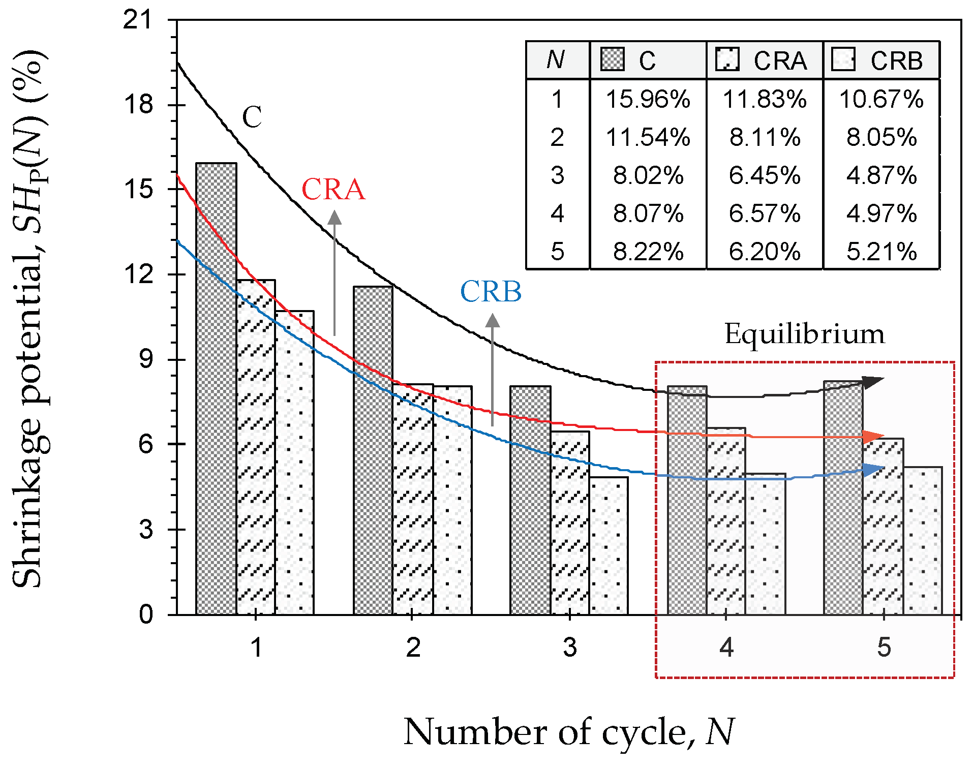
4.2. Shrinkage Characteristics

Figure 6 illustrates the variations of shrinkage potential SHP—obtained as per oedometer testing conditions—against the number of applied cycles N for the tested samples. The shrinkage potential demonstrated a trend similar to that observed for the swelling potential (compare Figure 4 and Figure 6). In this case, the greater the number of applied cycles, the lower the shrinkage potential, following a monotonically decreasing trend up to the equilibrium cycle (or N = 3–4), beyond which marginal variations were noted. For any given cycle, the rubberized blends, CRA and CRB, consistently outperformed the virgin soil, C, in terms of lower SHP values. The tendency for shrinkage reduction, however, was found to be in favor of a larger rubber size, as is evident with the lower SHP values (particularly at N ≥ 3) exhibited by CRB compared with that of CRA (compare the trendlines “CRA” and “CRB” in Figure 4). The virgin soil resulted in SHP = 15.96%, 11.54%, 8.02%, 8.07%, and 8.22% at N = 1–5, whereas the inclusion of 10% RA resulted in lower values of 11.83%, 8.11%, 6.45%, 6.57%, and 6.20%, respectively. The same 10% inclusion of RB demonstrated a more pronounced decreasing trend, as the aforementioned values dropped to SHP = 10.67%, 8.05%, 4.87%, 4.97%, and 5.21% (at N = 1–5), respectively.
Void ratio–water content shrinkage curves for the tested samples at N = 1 and 5 are provided in Figure 7. Much like the swell–time path (see Figure 3), the shrinkage curve also develops into an S-shaped curve, and thus suggests three phases during shrink evolvement, namely, structural, primary and residual shrinkage [44,46,60,61,62]. The structural shrinkage phase progresses at macrostructural level where drainage of water takes place from the larger inter-assemblage pore spaces. Consequently, this stage accounts for minor (and often negligible) changes in the bulk soil volume (e.g., see sample C at N = 1 in Figure 7a). The primary shrinkage stage is graphically represented by a steep-sloped linear relationship, indicating an escalated rate of shrinkage with respect to water loss. This portion of the shrinkage curve is theoretically parallel to the Sr = 100% saturation line, and as such, any decrease in water volume brings forth an equal decrease in the bulk soil volume. Primary shrinkage extends up to the shrinkage limit where particles come into close contact, and the contained water is just sufficient to fill the intra-assemblage pore spaces (e.g., see sample C at N = 1 in Figure 7a). The residual shrinkage phase marks the entrance of air into the intra-assemblage pore spaces, thereby promoting air-filled porosity coupled with a dense particle configuration. At this stage, the volume of lost water exceeds the decrease in bulk soil volume (e.g., see sample C at N = 1 in Figure 7a).
As a result of alternate wetting and drying, the shrinkage curve encountered a major vertical dilation over the e:w space, i.e., where e represents void ratio and w represents water content, indicating a reduced tendency for shrinkage. Furthermore, the primary shrinkage segment shifted away from its corresponding Sr = 100% saturation line, thus signifying a tendency towards a more unsaturated character upon achieving equilibrium condition (compare N = 1 with N = 5 in Figure 7). As a typical case outlined in Figure 7b (see sample CRB at N = 1), the shrinkage curve can be employed to obtain the volumetric shrinkage strain εvsh by means of basic volume–mass relations—εvsh = Δe/(1 + eo) where Δe represents change in void ratio, and eo represents initial void ratio. The virgin soil resulted in εvsh = 26.97% and 14.28% at N = 1 and 5, whereas the inclusion of 10% RA resulted in lower values of 20.33% and 10.73%, respectively. The same 10% inclusion of RB demonstrated a slightly more pronounced decreasing trend, as the aforementioned values dropped to εvsh = 19.60% and 9.85% (at N = 1 and 5), respectively. Cyclic wetting–drying and/or rubber inclusion led to a notable increase in the shrinkage limit wS. The effect of rubber size/shape, however, was found to be rather marginal. The samples C, CRA, and CRB resulted in wS = 14.88%, 18.00%, and 16.40% at N = 1, whereas the aforementioned values increased to 17.47%, 20.87%, and 19.92% at N = 5, respectively. The shrinkage limit is adversely related to the packing capacity of particles during drying, which in turn is governed by the grain-size distribution. The more uniform the grain-size distribution, the lower the packing capacity and hence the higher the shrinkage limit [63,64]. The addition of poorly graded rubber (see Table 3) offsets the well-graded distribution of the host soil, and thus gives rise to higher shrinkage limits. Similarly, cyclic wetting–drying leads to a more uniform grain-size distribution by inducing aggregation and cementation of the soil grains (see Section 4.4 for details), which in turn results in higher shrinkage limits.

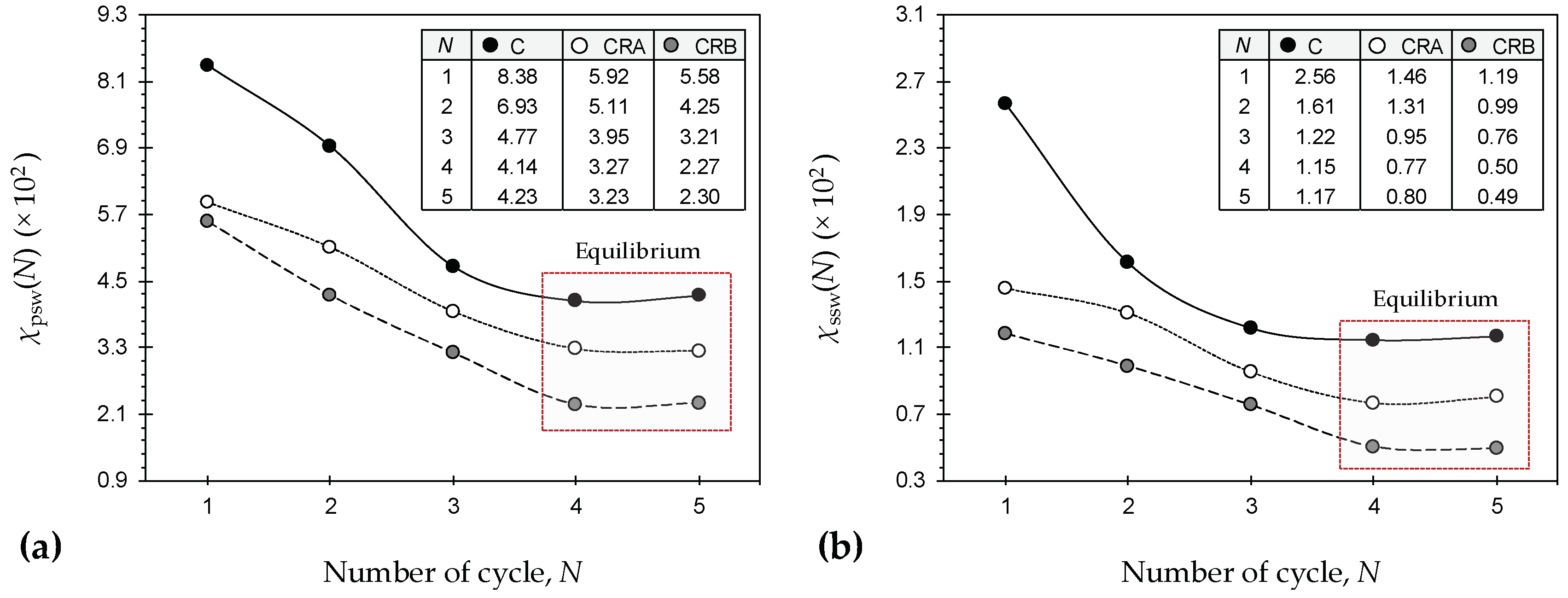
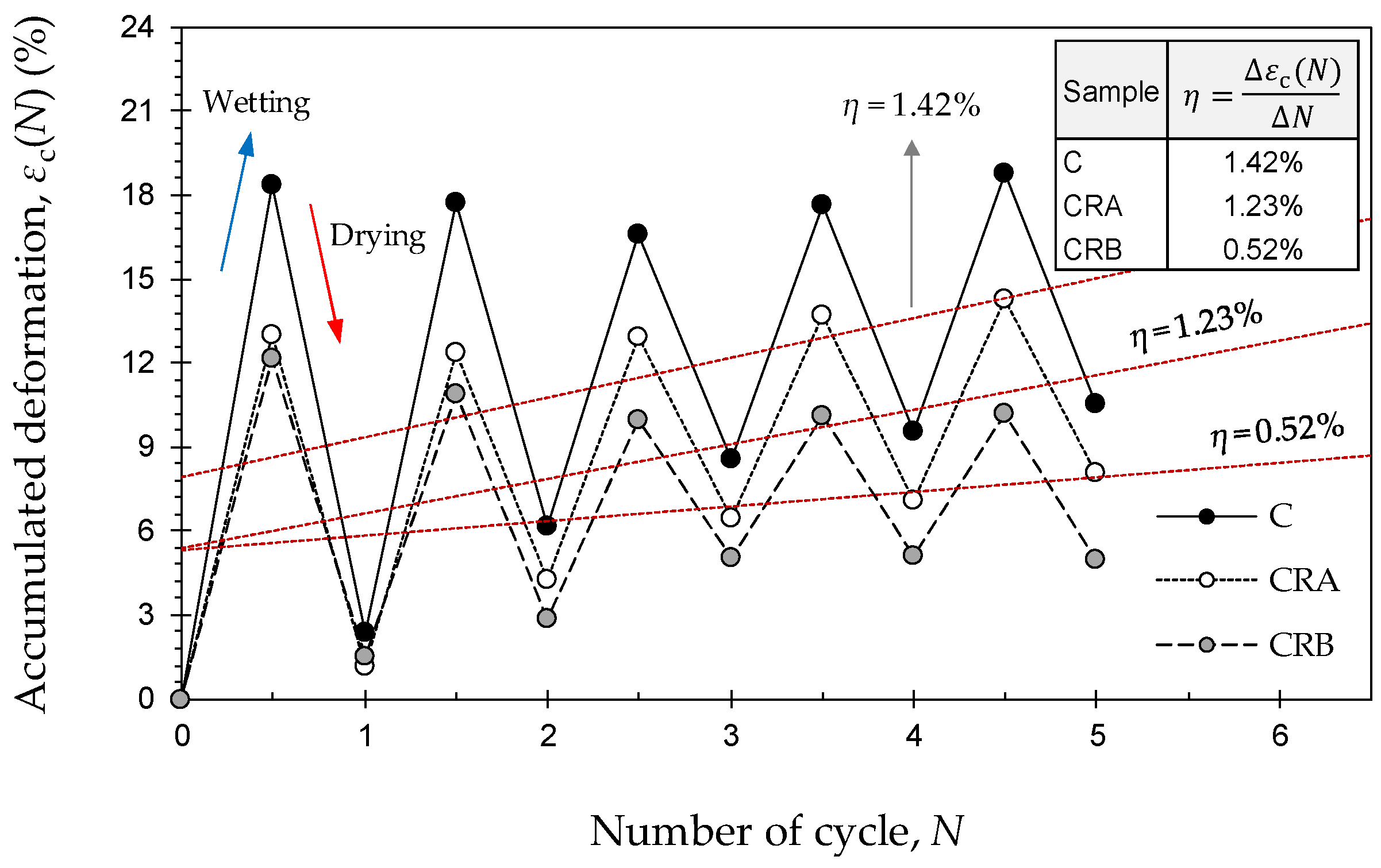
4.3. Swell–Shrink Patterns

The swelling and shrinkage potentials—obtained as per Equation (1) and illustrated in Figure 4 and Figure 6—n be incorporated in a cumulative manner to arrive at the accumulated axial deformation during alternate wetting and drying as follows [7,47]:
ε c ( N ) = { W : N = 1 [ S P ( N ) S H P ( N 1 ) ]     N = { 1 , 2 , 3 , } D : N = 1 [ S P ( N ) S H P ( N ) ]     N = { 1 , 2 , 3 , }
where εc(N) is accumulated axial deformation at the Nth wetting ‘W’ or drying ‘D’ cycle with respect to the sample’s initial (or as-compacted) placement condition.
The accumulated deformation plotted against the number of applied cycles, commonly referred to as the swell–shrink pattern/path, can be employed to perceive/predict free surface ground movements under field conditions. Swell–shrink paths for the samples C, CRA, and CRB are provided in Figure 8. As a result of rubber inclusion, the swell–shrink path, while lingering above the reference deformation level, εc = 0, encountered a notable downward shift over the εc:N space, thereby corroborating the rubber’s capacity to counteract the heave and/or settlement incurred by alternate wetting and drying. The nature and extent of the accumulated deformation can be interpreted by the slope of a two-parameter linear trendline fitted through the desired εcN dataset—η = Δεc/ΔN. Depending on the sign and magnitude of η, three scenarios can be hypothesized [7]:
  • η > 0: The magnitude of incurred swelling is greater than that of shrinkage, and as such, the accumulated deformation is expansive. Quite clearly, the greater the magnitude of η, the higher the expansive tendency.
  • η < 0: The magnitude of incurred shrinkage is greater than that of swelling, and as such, the accumulated deformation is contractive. In this case, the greater the magnitude of η, the higher the tendency for contraction.
  • η = 0: The magnitude of incurred swelling and shrinkage are on par with each other, and as such, the accumulated deformation is neutral and hence desirable for minimizing free surface ground movements.
In terms of η, the tested mix designs can be orderly ranked as C > CRA >> CRB. The virgin soil resulted in η = +1.42%, thus signifying an expansive accumulated deformation as a result of alternate wetting and drying. With the inclusion of 10% RA, the aforementioned value dropped to +1.23%, which indicates an expansive condition with lower expansive tendency compared with that of the virgin soil. The same 10% inclusion of RB, however, manifested a relatively neutral value of η = +0.52%, thereby suggesting a more effective resistance to alternate wetting and drying compared with that of RA.

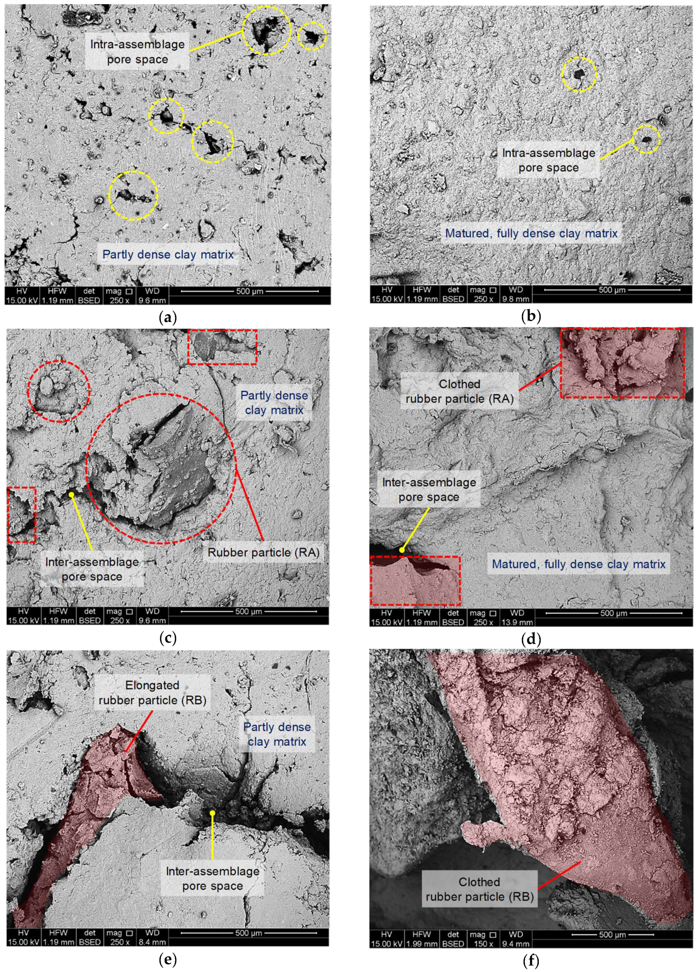
4.4. Amending Mechanisms and Fabric Evolution

The swelling and shrinkage potentials both exhibited a notable decreasing trend with an increase in the number of applied cycles (see Figure 4 and Figure 6). Such trends can be attributed to the reconstruction of the soil microstructure upon completion of the first or second cycle [2,40,43,46,47]. Capillary stresses generated as a consequence of drying facilitate the formation of strong van der Waals bonds capable of inducing aggregation and cementation of the soil grains. This is followed by a decrease in the expansive clay content, leading to a reduced specific surface area and hence a lower water adsorption–retention capacity, which in turn brings forth a reduced tendency for swelling and shrinkage. SEM micrographs for the samples C, CRA, and CRB, prior to and after cyclic wetting–drying (or N = 5), are provided in Figure 9.
The microfabric of the as-compacted virgin soil sample (without wetting–drying action) exhibited a partly dense matrix, along with a notable number of intra-assemblage pore spaces which facilitate the entrance of water into the sample during wetting (see Figure 9a). As a result of alternate wetting and drying, the microfabric became more uniform in nature, indicating aggregation and cementation of the soil grains and hence the development of a matured, fully dense matrix. Moreover, the intra-assemblage pore spaces displayed a notable reduction in both number and size, thereby leading to a decreased water intrusion capacity and hence a reduced tendency for swelling (see Figure 9b). Much like the as-compacted virgin soil sample, the microfabric of the as-compacted rubberized blends (i.e., CRA and CRB) consisted of a partly dense matrix, accompanied by a number of inter-assemblage pore spaces mainly distributed along the soil–rubber connection interface. The rubber inclusions effectively limited the clay’s available surface area for interaction with water, which in turn led to a reduced swelling potential compared with that of the as-compacted virgin soil sample. In addition, the rubber particles acted as physical anchors within the matrix, interlocking the neighboring clay aggregates and hence withstanding tensile stresses developed during desiccation (see Figure 9c,e). Quite clearly, the larger size and elongated form factor of RB makes for a more pronounced interlocking and hence a higher resistance against swelling and shrinkage compared with that of RA (compare Figure 9c,e). With the progression of cyclic wetting–drying, the connection interface between the rubber particles and the clay matrices was markedly improved, as is evident with the reduced number of inter-assemblage pore spaces, as well as the presence of clothed rubber particles; this in turn resulted in a further reduction of the swelling and shrinkage potentials (see Figure 9d,f).
Taking into account the above discussion, as well as those outlined in previous studies [2,29,30,37,39], the soil–rubber amending mechanisms can be ascribed to the following three aspects:
  • Increase in non-expansive content: The swell–shrink capacity is primarily a function of the soil’s expansive clay content, implying that the lower the expansive clay content, the lower the tendency for swelling and shrinkage. The rubber inclusions substitute a fraction of the expansive clay content with non-plastic, hydrophobic rubber particles, thereby leading to a decrease in the swell–shrink capacity.
  • Frictional resistance generated as a result of soil–rubber contact: The frictional resistance is a function of the soil–rubber contact area, with greater contact levels offering a higher resistance to bear the swell–shrink forces. Consequently, this amending mechanism can be ascribed to the rubber content, and potentially the rubber size or surface area (not shape). For any given rubber content, the coarser the rubber particles (or the lower the rubber’s specific surface area), the greater the achieved contact level (or interface) between the rubber particles and the soil grains, and thus the higher the generated frictional resistance against swelling and shrinkage (compare CRB with CRA in Figure 4 and Figure 6).
  • Mechanical interlocking of rubber particles and soil grains: Mechanical interlocking is achieved during sample preparation (or compaction), and induces matrix adhesion by immobilizing the soil grains against swell–shrink movements. Quite clearly, the more effective the achieved mechanical interlocking, the higher the resistance to swelling and shrinkage. Consequently, this amending mechanism is in line with the rubber content, and more importantly the rubber shape (not size or surface area). As opposed to the granular form factor of RA, the particles of RB are rather fiber-shaped or elongated (see Figure 1), and thus favor a more pronounced mechanical interlocking by entwining within the matrix and immobilizing the soil grains against swell–shrink movements with increased efficiency (compare CRB with CRA in Figure 4 and Figure 6).

5. Conclusions

The present study has arrived at the following conclusions:
  • Alternate wetting and drying led to the reconstruction of the soil/soil–rubber microstructure by way of inducing aggregation and cementation of the soil grains. The greater the number of applied cycles, the lower the swelling and shrinkage potentials, both following a monotonically decreasing trend, with the rubberized blends holding a notable advantage over the virgin soil. The tendency for reduction, however, was found to be in favor of a larger rubber size, thus signifying a rubber size/shape-dependent amending mechanism.
  • The axial swelling strain–time data (time in logarithmic scale) developed into an S-shaped curve, and thus suggested three phases during swell evolvement, namely, initial, primary, and secondary swelling. As a result of cyclic wetting–drying and/or rubber inclusion, the swell–time locus encountered a major downward shift, thereby indicating a capacity to counteract the heave in both magnitude and time.
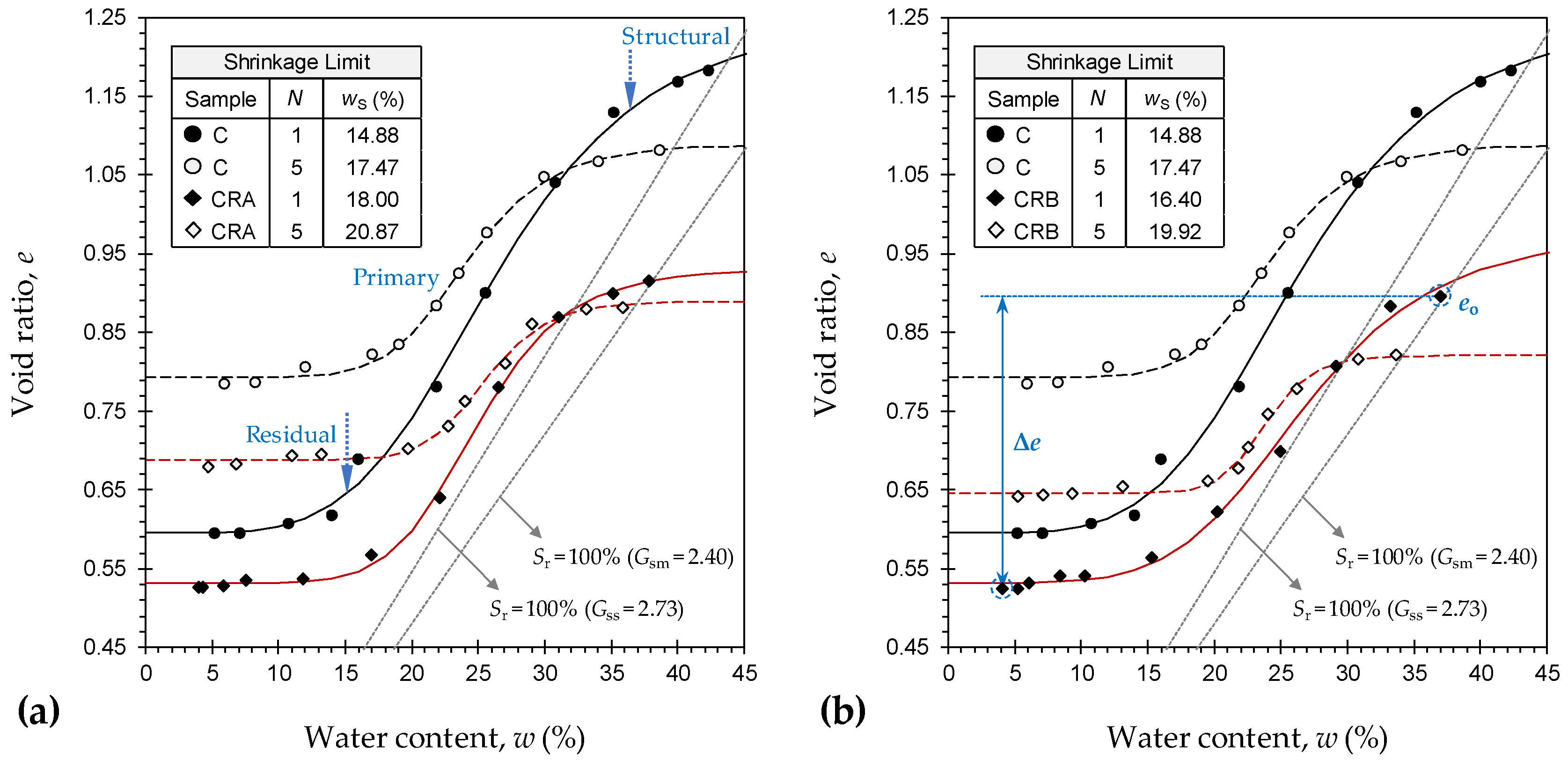
  • The void ratio–water content shrinkage data also developed into an S-shaped curve, and thus suggested three phases during shrink evolvement, namely, structural, primary, and residual shrinkage. As a result of cyclic wetting–drying and/or rubber inclusion, the shrinkage curve encountered a major vertical dilation, thus indicating a reduced tendency for shrinkage. Furthermore, alternate wetting and drying and/or rubber inclusion led to a notable increase in the shrinkage limit, whereas the effect of rubber size/shape was found to be marginal.
  • The rubber inclusions led to a notable decrease in the magnitude of the accumulated axial deformation during successive wetting–drying cycles. The swell–shrink patterns/paths indicated an expansive accumulated deformation for the virgin soil, whereas the rubberized blends, particularly the one blended with the rubber of coarser category, manifested a relatively neutral accumulated deformation, thereby corroborating the rubber’s capacity to counteract the heave and/or settlement incurred by alternate wetting and drying.

Author Contributions

Conceptualization, A.S., A.D., and A.T.; Methodology, A.S., A.D., A.T., and S.K.V.; Validation, A.S. and M.M.; Formal analysis, A.S. and M.M.; Investigation, A.S.; Writing—Original Draft preparation, A.S. and M.M.; Writing—Review and Editing, A.D., A.T., and S.K.V.; Visualization, A.S. and M.M.; Supervision, A.D., A.T., and S.K.V.; Funding acquisition, A.D. and A.T.

Funding

This research was funded by the Australian Research Council (ARC) under Project No. DP140103004; this support is gratefully acknowledged.

Acknowledgments

Special thanks go to Asuri Sridharan of the Indian National Science Academy (INSA) for valuable suggestions to the authors. This research was made possible through the provision of an Australian Government Research Training Program Scholarship; this support is gratefully acknowledged.

Conflicts of Interest

The authors declare no conflict of interest.

References

  1. Jones, L.D.; Jefferson, I. Expansive soils. In ICE Manual of Geotechnical Engineering: Volume I; Burland, J., Chapman, T., Brown, M., Skinner, H., Eds.; ICE Publishing: London, UK, 2012; pp. 413–441. ISBN 9780727757081. [Google Scholar] [CrossRef]
  2. Soltani, A.; Deng, A.; Taheri, A.; Mirzababaei, M. Rubber powder–polymer combined stabilization of South Australian expansive soils. Geosynth. Int. 2018, 25, 304–321. [Google Scholar] [CrossRef]
  3. Soltani, A.; Taheri, A.; Khatibi, M.; Estabragh, A.R. Swelling potential of a stabilized expansive soil: A comparative experimental study. Geotech. Geol. Eng. 2017, 35, 1717–1744. [Google Scholar] [CrossRef]
  4. Estabragh, A.R.; Rafatjo, H.; Javadi, A.A. Treatment of an expansive soil by mechanical and chemical techniques. Geosynth. Int. 2014, 21, 233–243. [Google Scholar] [CrossRef]
  5. Onyejekwe, S.; Ghataora, G.S. Soil stabilization using proprietary liquid chemical stabilizers: Sulphonated oil and a polymer. Bull. Eng. Geol. Environ. 2015, 74, 651–665. [Google Scholar] [CrossRef]
  6. Alazigha, D.P.; Indraratna, B.; Vinod, J.S.; Ezeajugh, L.E. The swelling behaviour of lignosulfonate-treated expansive soil. Proc. Inst. Civ. Eng. Ground Improv. 2016, 169, 182–193. [Google Scholar] [CrossRef]
  7. Soltani, A.; Deng, A.; Taheri, A.; Mirzababaei, M. A sulphonated oil for stabilisation of expansive soils. Int. J. Pavement Eng. 2017. [Google Scholar] [CrossRef]
  8. Mirzababaei, M.; Arulrajah, A.; Horpibulsuk, S.; Soltani, A.; Khayat, N. Stabilization of soft clay using short fibers and poly vinyl alcohol. Geotext. Geomembr. 2018, 46, 646–655. [Google Scholar] [CrossRef]
  9. Zhang, J.; Soltani, A.; Deng, A.; Jaksa, M.B. Mechanical performance of jute fiber-reinforced micaceous clay composites treated with ground-granulated blast-furnace slag. Materials 2019, 12, 576. [Google Scholar] [CrossRef]
  10. Al-Omari, R.R.; Hamodi, F.J. Swelling resistant geogrid—A new approach for the treatment of expansive soils. Geotext. Geomembr. 1991, 10, 295–317. [Google Scholar] [CrossRef]
  11. Al-Akhras, N.M.; Attom, M.F.; Al-Akhras, K.M.; Malkawi, A.I.H. Influence of fibers on swelling properties of clayey soil. Geosynth. Int. 2008, 15, 304–309. [Google Scholar] [CrossRef]
  12. Viswanadham, B.V.S.; Phanikumar, B.R.; Mukherjee, R.V. Swelling behaviour of a geofiber-reinforced expansive soil. Geotext. Geomembr. 2009, 27, 73–76. [Google Scholar] [CrossRef]
  13. Phanikumar, B.R.; Singla, R. Swell–consolidation characteristics of fibre-reinforced expansive soils. Soils Found. 2016, 56, 138–143. [Google Scholar] [CrossRef]
  14. Soltani, A.; Deng, A.; Taheri, A. Swell‒compression characteristics of a fiber-reinforced expansive soil. Geotext. Geomembr. 2018, 46, 183–189. [Google Scholar] [CrossRef]
  15. Mirzababaei, M.; Miraftab, M.; Mohamed, M.; McMahon, P. Impact of carpet waste fibre addition on swelling properties of compacted clays. Geotech. Geol. Eng. 2013, 31, 173–182. [Google Scholar] [CrossRef]
  16. Arulrajah, A.; Mohammadinia, A.; D’Amico, A.; Horpibulsuk, S. Effect of lime kiln dust as an alternative binder in the stabilization of construction and demolition materials. Constr. Build. Mater. 2017, 152. [Google Scholar] [CrossRef]
  17. Kua, T.A.; Arulrajah, A.; Mohammadinia, A.; Horpibulsuk, S.; Mirzababaei, M. Stiffness and deformation properties of spent coffee grounds based geopolymers. Constr. Build. Mater. 2017, 138, 79–87. [Google Scholar] [CrossRef]
  18. Mirzababaei, M.; Mohamed, M.; Arulrajah, A.; Horpibulsuk, S.; Anggraini, V. Practical approach to predict the shear strength of fibre-reinforced clay. Geosynth. Int. 2018, 25, 50–66. [Google Scholar] [CrossRef]
  19. Phummiphan, I.; Horpibulsuk, S.; Rachan, R.; Arulrajah, A.; Shen, S.L.; Chindaprasirt, P. High calcium fly ash geopolymer stabilized lateritic soil and granulated blast furnace slag blends as a pavement base material. J. Hazard. Mater. 2018, 341, 257–267. [Google Scholar] [CrossRef]
  20. Soltani, A.; Deng, A.; Taheri, A.; Mirzababaei, M.; Nikraz, H. Interfacial shear strength of rubber-reinforced clays: A dimensional analysis perspective. Geosynth. Int. 2019. [Google Scholar] [CrossRef]
  21. Edil, T.; Bosscher, P. Engineering properties of tire chips and soil mixtures. Geotech. Test. J. 1994, 17, 453–464. [Google Scholar] [CrossRef]
  22. Foose, G.J.; Benson, C.H.; Bosscher, P.J. Sand reinforced with shredded waste tires. J. Geotech. Eng. 1996, 122, 760–767. [Google Scholar] [CrossRef]
  23. Al-Tabbaa, A.; Blackwell, O.; Porter, S.A. An investigation into the geotechnical properties of soil–tyre mixtures. Environ. Technol. 1997, 18, 855–860. [Google Scholar] [CrossRef]
  24. Lee, J.H.; Salgado, R.; Bernal, A.; Lovell, C.W. Shredded tires and rubber sand as lightweight backfill. J. Geotech. Geoenviron. Eng. 1999, 125, 132–141. [Google Scholar] [CrossRef]
  25. Zornberg, J.G.; Cabral, A.R.; Viratjandr, C. Behaviour of tire shred–sand mixtures. Can. Geotech. J. 2004, 41, 227–241. [Google Scholar] [CrossRef]
  26. Al-Tabbaa, A.; Aravinthan, T. Natural clay–shredded tire mixtures as landfill barrier materials. Waste Manag. 1998, 18, 9–16. [Google Scholar] [CrossRef]
  27. Cokca, E.; Yilmaz, Z. Use of rubber and bentonite added fly ash as a liner material. Waste Manag. 2004, 24, 153–164. [Google Scholar] [CrossRef]
  28. Seda, J.H.; Lee, J.C.; Carraro, J.A.H. Beneficial use of waste tire rubber for swelling potential mitigation in expansive soils. In Geo-Denver 2007: Soil Improvement (GSP 172); Schaefer, V.R., Filz, G.M., Gallagher, P.M., Sehn, A.L., Wissmann, K.J., Eds.; ASCE: Denver, CO, USA, 2007; pp. 1–9. [Google Scholar] [CrossRef]
  29. Patil, U.; Valdes, J.R.; Evans, T.M. Swell mitigation with granulated tire rubber. J. Mater. Civ. Eng. 2011, 23, 721–727. [Google Scholar] [CrossRef]
  30. Trouzine, H.; Bekhiti, M.; Asroun, A. Effects of scrap tyre rubber fibre on swelling behaviour of two clayey soils in Algeria. Geosynth. Int. 2012, 19, 124–132. [Google Scholar] [CrossRef]
  31. Kalkan, E. Preparation of scrap tire rubber fiber–silica fume mixtures for modification of clayey soils. Appl. Clay Sci. 2013, 80–81, 117–125. [Google Scholar] [CrossRef]
  32. Cabalar, A.F.; Karabash, Z.; Mustafa, W.S. Stabilising a clay using tyre buffings and lime. Road Mater. Pavement Des. 2014, 15, 872–891. [Google Scholar] [CrossRef]
  33. Srivastava, A.; Pandey, S.; Rana, J. Use of shredded tyre waste in improving the geotechnical properties of expansive black cotton soil. Geomech. Geoengin. 2014, 9, 303–311. [Google Scholar] [CrossRef]
  34. Signes, C.H.; Garzón-Roca, J.; Fernández, P.M.; Torre, M.E.G.; Franco, R.I. Swelling potential reduction of Spanish argillaceous marlstone Facies Tap soil through the addition of crumb rubber particles from scrap tyres. Appl. Clay Sci. 2016, 132–133, 768–773. [Google Scholar] [CrossRef]
  35. Mukherjee, K.; Mishra, A.K. The impact of scrapped tyre chips on the mechanical properties of liner materials. Environ. Process. 2017, 4, 219–233. [Google Scholar] [CrossRef]
  36. Yadav, J.S.; Tiwari, S.K. A study on the potential utilization of crumb rubber in cement treated soft clay. J. Build. Eng. 2017, 9, 177–191. [Google Scholar] [CrossRef]
  37. Yadav, J.S.; Tiwari, S.K. Effect of waste rubber fibres on the geotechnical properties of clay stabilized with cement. Appl. Clay Sci. 2017, 149, 97–110. [Google Scholar] [CrossRef]
  38. Mukherjee, K.; Mishra, A.K. Hydraulic and mechanical characteristics of compacted sand–bentonite: Tyre chips mix for its landfill application. Environ. Dev. Sustain. 2018. [Google Scholar] [CrossRef]
  39. Soltani, A.; Deng, A.; Taheri, A.; Sridharan, A. Swell–shrink–consolidation behavior of rubber-reinforced expansive soils. Geotech. Test. J. 2018. [Google Scholar] [CrossRef]
  40. Zhang, R.; Yang, H.; Zheng, J. The effect of vertical pressure on the deformation and strength of expansive soil during cyclic wetting and drying. In Unsaturated Soils 2006: Proceedings of the Fourth International Conference on Unsaturated Soils; Miller, G.A., Zapata, C.E., Houston, S.L., Fredlund, D.G., Eds.; ASCE: Carefree, AZ, USA, 2006; pp. 894–905. [Google Scholar] [CrossRef]
  41. Dif, A.; Bluemel, W. Expansive soils under cyclic drying and wetting. Geotech. Test. J. 1991, 14, 96–102. [Google Scholar] [CrossRef]
  42. Al-Homoud, A.S.; Basma, A.A.; Malkawi, A.I.H.; Al-Bashabsheh, M.A. Cyclic swelling behaviour of clays. J. Geotech. Eng. 1995, 121, 562–565. [Google Scholar] [CrossRef]
  43. Subba Rao, K.S. Swell–shrink behaviour of expansive Soils—Geotechnical challenges. Indian Geotech. J. 2000, 30, 1–68. [Google Scholar]
  44. Tripathy, S.; Subba Rao, K.S.; Fredlund, D.G. Water content–void ratio swell–shrink paths of compacted expansive soils. Can. Geotech. J. 2002, 39, 938–959. [Google Scholar] [CrossRef]
  45. Tripathy, S.; Subba Rao, K.S. Cyclic swell–shrink behaviour of a compacted expansive soil. Geotech. Geol. Eng. 2009, 27, 89–103. [Google Scholar] [CrossRef]
  46. Estabragh, A.R.; Parsaei, B.; Javadi, A.A. Laboratory investigation of the effect of cyclic wetting and drying on the behaviour of an expansive soil. Soils Found. 2015, 55, 304–314. [Google Scholar] [CrossRef]
  47. Zhao, N.F.; Ye, W.M.; Chen, Y.G.; Chen, B.; Cui, Y.J. Investigation on swelling–shrinkage behavior of unsaturated compacted GMZ bentonite on wetting–drying cycles. Bull. Eng. Geol. Environ. 2019, 78, 617–627. [Google Scholar] [CrossRef]
  48. Estabragh, A.R.; Soltani, A.; Javadi, A.A. Effect of pore water chemistry on the behaviour of a kaolin–bentonite mixture during drying and wetting cycles. Eur. J. Environ. Civ. Eng. 2018. [Google Scholar] [CrossRef]
  49. Guney, Y.; Sari, D.; Cetin, M.; Tuncan, M. Impact of cyclic wetting–drying on swelling behavior of lime-stabilized soil. Build. Environ. 2007, 42, 681–688. [Google Scholar] [CrossRef]
  50. Yazdandoust, F.; Yasrobi, S.S. Effect of cyclic wetting and drying on swelling behavior of polymer-stabilized expansive clays. Appl. Clay Sci. 2010, 50, 461–468. [Google Scholar] [CrossRef]
  51. Kalkan, E. Impact of wetting–drying cycles on swelling behavior of clayey soils modified by silica fume. Appl. Clay Sci. 2011, 52, 345–352. [Google Scholar] [CrossRef]
  52. Estabragh, A.R.; Pereshkafti, M.R.S.; Parsaei, B.; Javadi, A.A. Stabilised expansive soil behaviour during wetting and drying. Int. J. Pavement Eng. 2013, 14, 418–427. [Google Scholar] [CrossRef]
  53. Alazigha, D.P.; Vinod, J.S.; Indraratna, B.; Heitor, A. Potential use of lignosulfonate for expansive soil stabilisation. Environ. Geotech. 2018. [Google Scholar] [CrossRef]
  54. Sridharan, A.; Nagaraj, H.B. Compressibility behaviour of remoulded, fine-grained soils and correlation with index properties. Can. Geotech. J. 2000, 37, 712–722. [Google Scholar] [CrossRef]
  55. Prakash, K.; Sridharan, A. Free swell ratio and clay mineralogy of fine-grained soils. Geotech. Test. J. 2004, 27, 220–225. [Google Scholar] [CrossRef]
  56. Yadav, J.S.; Tiwari, S.K. The impact of end-of-life tires on the mechanical properties of fine-grained soil: A Review. Environ. Dev. Sustain. 2017. [Google Scholar] [CrossRef]
  57. Sivapullaiah, P.V.; Sridharan, A.; Stalin, V.K. Swelling behaviour of soil–bentonite mixtures. Can. Geotech. J. 1996, 33, 808–814. [Google Scholar] [CrossRef]
  58. Day, R.W. Geotechnical and Foundation Engineering: Design and Construction, 1st ed.; McGraw-Hill: New York, NY, USA, 1999; ISBN 0071341382. [Google Scholar]
  59. Sridharan, A.; Gurtug, Y. Swelling behaviour of compacted fine-grained soils. Eng. Geol. 2004, 72, 9–18. [Google Scholar] [CrossRef]
  60. Haines, W.B. The volume-changes associated with variations of water content in soil. J. Agric. Sci. 1923, 13, 296–310. [Google Scholar] [CrossRef]
  61. Cornelis, W.M.; Corluy, J.; Medina, H.; Díaz, J.; Hartmann, R.; van Meirvenne, M.; Ruiz, M.E. Measuring and modelling the soil shrinkage characteristic curve. Geoderma 2006, 137, 179–191. [Google Scholar] [CrossRef]
  62. Thyagaraj, T.; Thomas, S.R.; Das, A.P. Physico-chemical effects on shrinkage behavior of compacted expansive clay. Int. J. Geomech. 2017, 17, 06016013:1–06016013:11. [Google Scholar] [CrossRef]
  63. Sridharan, A.; Prakash, K. Mechanism controlling the shrinkage limit of soils. Geotech. Test. J. 1998, 21, 240–250. [Google Scholar] [CrossRef]
  64. Sridharan, A.; Prakash, K. Shrinkage limit of soil mixtures. Geotech. Test. J. 2000, 23, 3–8. [Google Scholar] [CrossRef]
Figure 1. Recycled tire rubbers at different magnification ratios: (a) RA (no magnification); (b) RA (150×); (c) RA (500×); (d) RB (no magnification); (e) RB (150×); and (f) RB (250×).
Minerals 09 00224 g001
Figure 2. Standard Proctor compaction curves for the tested mix designs (ZAV is zero air voids): (a) C and CRA; and (b) C and CRB.
Minerals 09 00224 g002
Figure 3. Swell–time curves during alternate wetting cycles: (a) C; (b) CRA; and (c) CRB.
Minerals 09 00224 g003aMinerals 09 00224 g003b
Figure 4. Variations of swelling potential against the number of applied cycles for the tested samples.
Minerals 09 00224 g004
Figure 5. Rate of swelling for the tested samples during alternate wetting cycles: (a) primary swelling coefficient; and (b) secondary swelling coefficient.
Minerals 09 00224 g005
Figure 6. Variations of shrinkage potential against the number of applied cycles for the tested samples.
Minerals 09 00224 g006
Figure 7. Void ratio–water content shrinkage curves, at N = 1 and 5, for the tested samples: (a) C and CRA; and (b) C and CRB.
Minerals 09 00224 g007
Figure 8. Swell–shrink patterns for the tested samples.
Minerals 09 00224 g008
Figure 9. Scanning electron microscopy (SEM) micrographs for the tested samples: (a) C (as-compacted); (b) C (N = 5); (c) CRA (as-compacted); (d) CRA (N = 5); (e) CRB (as-compacted); and (f) CRB (N = 5).
Minerals 09 00224 g009
Table 1. Recent contributions addressing the swelling behavior of rubber mixed expansive clays.
SourcewL (%) 1IP (%) 2USCS 3RubberRubber Size (mm)Rubber Content (%)Binder(s)
[26]3412CL 4Shreds1–4; 4–86–15 (M)
[27]---Crumbs0.08–0.851–10 (M)Bentonite
[28]5234CH 5Shreds2–6.730 (V)
[29]8158CHCrumbs0.075–0.8520–36 (V)
[30]4522CI 6Fibers5–30 (L)10–50 (M)
[30]13383CHFibers5–30 (L)10–50 (M)
[31]7237MH 7Fibers5–10 (L), 0.25–1.25 (W)1–4 (M)Silica fume
[32]5027CIBuffings0.6–4.755–15 (M)Lime
[33]6132CHShreds0.075–2; 2–4.755–50 (M)
[34]5228CHCrumbs0.08–22.5–25 (M)
[35]32--Chips2–4.755–15 (M)
[36]349CICrumbs0.8–22.5–10 (M)Cement
[37]349CIFibers10–15 (L), 2–3 (W)2.5–10 (M)Cement
[38]---Chips2–4.755–15 (M)
[2]7856CHCrumbs0.075–1.1810–30 (M)PAM 8
[39]6033CHCrumbs0.075–1.185–30 (M)
[39]6033CHBuffings1.18–4.755–30 (M)
1 Liquid limit; 2 Plasticity index; 3 Unified Soil Classification System; 4 Clay with low plasticity; 5 Clay with high plasticity; 6 Clay with intermediate plasticity; 7 Silt with high plasticity; 8 Polyacrylamide; (M) is mass fraction; (V) is volume fraction; (L) is length; and (W) is width.
Table 2. Physical and mechanical properties of the expansive clay soil.
PropertiesValueStandard Designation
Specific gravity, Gss2.73ASTM D854–14
Clay [<2 μm] (%)52.80ASTM D422–07
Silt [2–75 μm] (%)46.16ASTM D422–07
Fine sand [0.075–0.425 mm] (%)1.04ASTM D422–07
Liquid limit, wL (%)59.60AS 1289.3.9.1–15
Plastic limit, wP (%)27.28AS 1289.3.2.1–09
Plasticity index, IP (%) 132.32AS 1289.3.3.1–09
Linear shrinkage, LS (%)8.19AS 1289.3.4.1–08
Shrinkage index, IS (%) 251.41Sridharan and Nagaraj [54]
USCS classificationCHASTM D2487–11
Free swell ratio, FSR 32.91Prakash and Sridharan [55]
Degree of expansivityHighPrakash and Sridharan [55]
Optimum water content, wopt (%)26.00ASTM D698–12
Maximum dry unit weight, γdmax (kN/m3)15.07ASTM D698–12
Unconfined compressive strength, qu (kPa) 4112.62ASTM D2166–16
Splitting tensile strength, qs (kPa) 413.57ASTM C496–17
1IP = wLwP; 2 IS = wLLS; 3 Ratio of equilibrium sediment volume of 10 g oven-dried soil passing sieve 425 μm in distilled water to that of kerosene; and 4 Tested at standard Proctor optimum condition.
Table 3. Physical properties and chemical composition of the recycled tire rubbers.
PropertiesCrumbs (RA)Buffings (RB)
Specific gravity (at 20 °C), Gsr1.091.09
Particle diameter D10 (mm)0.1821.077
Particle diameter D30 (mm)0.3341.370
Particle diameter D60 (mm)0.5131.682
Particle diameter D90 (mm)0.8642.105
Coefficient of uniformity, Cu 12.811.56
Coefficient of curvature, Cc 21.201.04
USCS classification 3SP 4SP
Water adsorption (%)<4<4
Softening point (°C)170170
Solubility in waterInsolubleInsoluble
Resistance to acid/alkalineExcellentExcellent
Styrene–butadiene copolymer (wt %)5555
Carbon black (wt %)25–3525–35
Acetone extract (wt %)5–205–20
Zinc oxide (wt %)2–32–3
Sulphur (wt %)1–31–3
1Cu = D60/D10; 2 Cc = D302/(D10D60); 3 ASTM D2487–11 method; and 4 Poorly graded sand.

