Article

Improving the Quality of Ferruginous Chromite Concentrates Via Physical Separation Methods

1
Research and Development Division, Tata Steel Ltd., Jamshedpur 831001, India
2
GeoRessources, University of Lorraine, CNRS, UMR 7359, F54505 Nancy, France
*
Author to whom correspondence should be addressed.
Minerals 2019, 9(11), 667; https://doi.org/10.3390/min9110667
Submission received: 8 October 2019 / Revised: 27 October 2019 / Accepted: 28 October 2019 / Published: 29 October 2019
(This article belongs to the Special Issue Physical Separation and Enrichment)

Abstract

:
The low chromium-to-iron ratio of chromite ores is an important issue in some chromite deposits. The value of the chromite ore is indeed dictated in the market by its iron, as well as its chromium content. In the present study, a chromite concentrate was reprocessed by gravity (spiral concentrator) and magnetic separation to enhance the chromium-to-iron ratio. Also, detailed characterization studies including automated mineralogy were carried out to better understand the nature of the samples. Enhancing the chromium-to-iron ratio was achieved by using advanced spiral separators which will be discussed in this paper.

1. Introduction

Chromite is the only available source of chromium metal which is used for alloy steels in the form of ferrochrome. Production of ferroalloy is a high energy-intensive process and the economics of the process depends on the associated impurity level. Among the impurities, iron is one of the gangue element, which is present in the form of gangue minerals as well as in the chromite crystal lattice. It is well reported in the literature that the chromium-to-iron ratio (Cr:Fe ratio) of chromite ores plays a crucial role in the efficiency of ferrochrome production [1,2,3]. For removal of the gangue minerals, including iron-bearing minerals, beneficiation is mandatory prior to the smelting process [4,5,6]. Conventionally, the chromite ore is beneficiated by using gravity concentration techniques. With the decrease in the particle size, separation of the chromite particles by gravity separation becomes difficult due to the presence of near density gangue minerals as well as limitation in the equipment design [7]. Thus, the improvement in the Cr:Fe ratio of the product is limited with ferruginous chromite ore deposits compared to the siliceous type deposits. Beyond a specific limit, it is challenging to process these iron-bearing minerals by using conventional gravity separators [4,8,9].
Beneficiation flow sheets generally consist of different classifiers (mechanical screw classifiers, hydraulic based hindered settling classifiers as well as hydro cyclones), gravity units (jig, heavy media cyclones/separators, spiral concentrators as well as shaking tables) and dewatering processes (thickening and filtration). The ferruginous chromite ore deposits are mostly found in India. The achievable Cr:Fe ratio of the concentrates varies from 1.5 to 2.8 from a low-grade deposit with Cr:Fe ratios of 0.5 to 1.0 by using gravity separation [4,10,11,12,13].
There are few published data available about processing low-grade deposits or tailings in order to beneficiate chromite. Publications relevant to the gravity separation of different chromite deposits as well as tailing fraction were studied [10,14,15,16,17,18,19,20]. Most of these studies are limited to the flowsheet development, as well as recovery of the chromite particles. Gravity separators (water only cyclone, multi-gravity separator, and knelson concentrator) have also been used to improve the product quality of low-grade chromite ores as well as tailings of the beneficiation plant [12,16,17,21,22,23,24]. It should be added that the higher centrifugal Falcon separator has not been studied for chromite ores although this device is widely used in the mineral industry [25,26]. There are published papers available on magnetic separation as well as roasting assisted magnetic separation to discard the iron-bearing gangue minerals [9,13,27,28,29,30,31]. Flotation, selective flocculation, as well as magnetic carrier separation studies have also been carried out for different chromite ores to separate chromite from the gangue minerals [32,33,34,35,36,37,38,39]. However, most of the studied ores are either synthetic samples, or silicate rich gangue minerals. It should be mentioned that while separation of iron from chromite ore is reported in the literature, the separation feature from the concentrate produced by gravity separation is not available. Gravity concentration is a viable option due to the difference in the density of the associated gangue minerals and chromite. Also, some case studies discussed on the application of spiral concentrator for treating such ores from the gangue minerals. Furthermore, the spiral concentrator is widely used for separation of minerals due to its lower operating cost. The other option for treating such materials is by utilizing the difference between the magnetic susceptibility of the minerals. The wet high-intensity magnetic separator is a common piece of industrial equipment for treating ferrous minerals. In this case, the gangue minerals exhibit paramagnetic property due to their iron content. Therefore, any study in this direction will assist on the amenability for the enhancement of the Cr:Fe ratio from ferruginous chromite ores.
In this paper, the enhancement of the Cr:Fe ratio of a chromite ore was investigated by reprocessing via gravity separation and magnetic separation. A number of experiments were carried out by varying the critical variables of these units. The ore samples were thoroughly characterized by different techniques including automated advanced mineralogical tools.

2. Materials and Methods

2.1. Chromite Samples

Three different chromite samples were collected from a beneficiation plant as coarse, fine, and ultrafine concentrates. The chromite ore is from an open cast mine at the Sukinda region, India, and treated in a gravity-based plant. In the plant, the chromite ore was beneficiated by grinding to below 1 mm and classification to three different size fractions (by using hydrocyclone and hydraulic classifiers). Each fraction was subjected to three-stage separation (a combination of a rougher–scavenger–cleaner circuit) in spiral concentrators with different designs. The concentrate samples were filtered and dried and about 1 ton of each fractions was collected for this study.

2.2. Particle Characterisation

The particle size distribution (PSD) of the sample was measured in a laboratory sieve shaker. ICP-AES (Integra XL, I.R. Tech. Pvt. Ltd. (GBC Scientific Equipment, Victoria, Australia )) was carried out for the chemical assays. The mineral analysis was carried out by X-ray diffraction (XRD) supplied by PANanalytical B.V. (Malvern Panalytical, Almelo, The Netherlands) and QEMSCAN (FEI Company, Hillsboro, OR, United States). The details of these procedures are given in earlier publications [8,40].

2.3. Separation Processes

To enhance the Cr:Fe ratio of the samples, gravity concentration by the spiral concentrator and magnetic separation by the wet-high intensity magnetic separator was used. The details of the experimental setup along with the process conditions are discussed in Section 2.3.1 and Section 2.3.2.

2.3.1. Spiral Concentrator Tests

Tests were carried out by varying the slurry flow rate and feed pulp density in two different spiral designs (HG10i and FM1 (Mineral Technologies, Carrara, Australia)). The other variables, such as splitter position, were maintained constant. Important parameters of the spiral concentrators and their design features along with the process conditions are given in Table 1. Experiments were carried out by varying the listed variables and operated in closed circuit arrangement whereby the product streams were recycled back to the feed tank. A valve located on the feed line was used to adjust the desired feed rate. The splitter position was maintained at 18 and 21 cm, respectively, for the HG10i and FM1 designs. The sampling was planned after setting the slurry flow rate with the designated slurry pulp density and it was allowed to run until a steady flow of the products streams achieved (i.e., more than 5 min). The products were collected, dried, weighed, and analyzed for the efficiency.

2.3.2. Wet High Intensity Magnetic Concentrator Tests

Tests were carried out on a pilot-scale wet high-intensity magnetic separator (Jones P40 model WHIMS, MBE Coal & Minerals Technology GmbH, Gottfried-Hagen-Straße 20, Germany) by varying the magnetic field intensity at the different levels (0.4 to 1.35 T). The slurry pulp density and feed rate were maintained at 10% and 0.1 tph, respectively. Wash water flow rate of the WHIMS was also maintained at 7 L·min−1. Also, the samples were also treated in two-stage at different magnetic field intensity. In the 1st stage, it was targeted to discard the non-magnetic particles at higher magnetic field intensity whereas paramagnetic minerals were targeted at a lower magnetic field intensity in the 2nd stage.

2.3.3. Experimental Analysis

After each experiment, the products (magnetic, middling, and non-magnetic for the WHIMS, and concentrate, middling, and tailing for the spiral concentrator) were collected for a fixed time, and dried. The weight distribution, as well as the elemental analysis for each product was measured and used for analyzing the grade, recovery, the Cr:Fe ratio and the Cr:Fe enrichment ratio. All tests were repeated at least 3 times, and the experimental error was found to be ±5%. The recovery and enrichment ratio for each test were calculated using Equations (1) and (2).
R e c o v e r y   % C r 2 O 3 = 100 × M a s s   s p l i t × G r a d e   % C r 2 O 3   o f   t h e   p r o d u c t G r a d e   % C r 2 O 3   o f   t h e   f e e d
C r : F e   e n r i c h m e n t   r a t i o = C r : F e   r a t i o   o f   t h e   p r o d u c t   C r : F e   r a t i o   o f   t h e   f e e d

3. Result and Discussion

3.1. Characterisation Studies

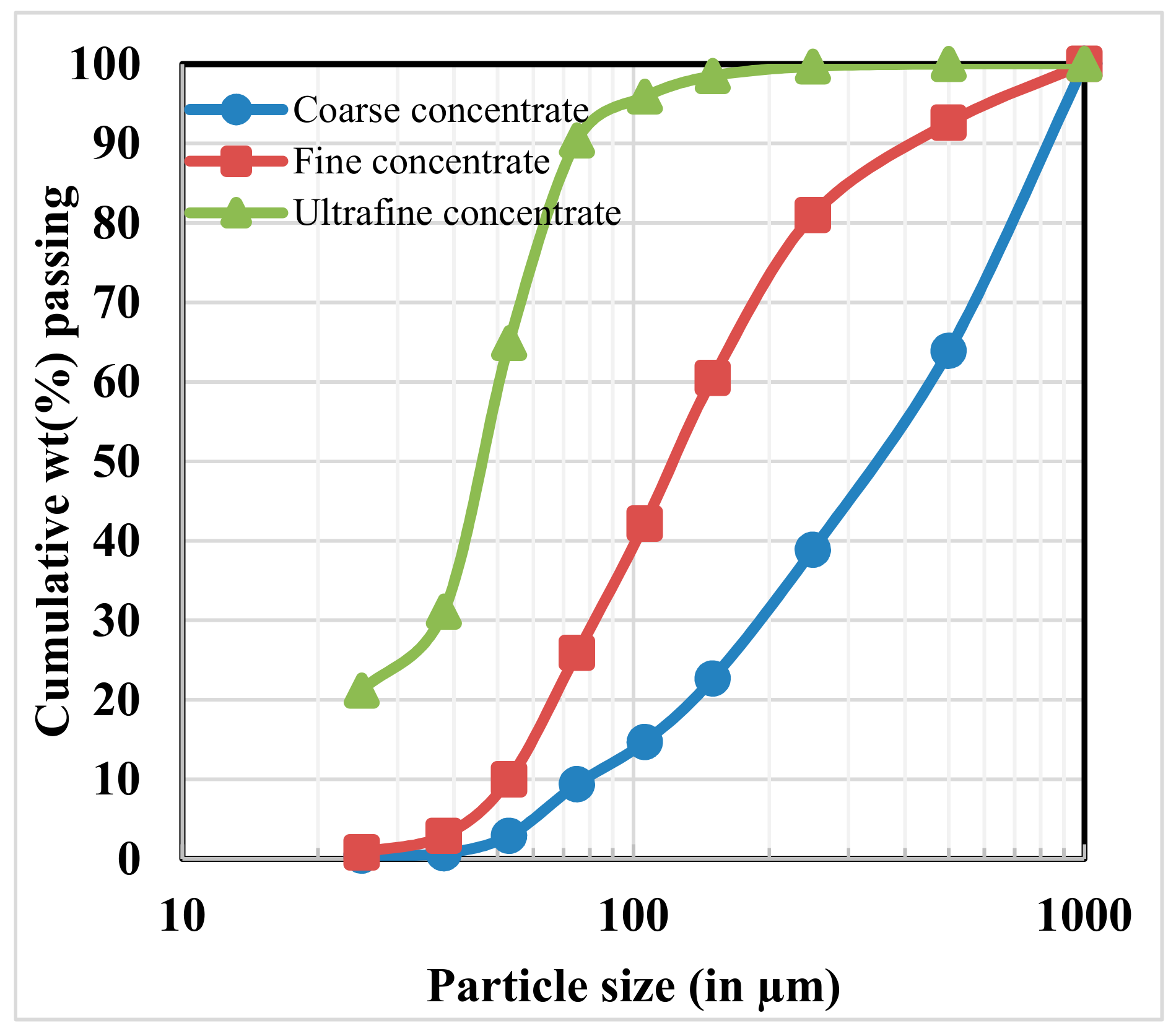
3.1.1. Particle Size and Chemical Analysis

The PSD of the chromite concentrates is given in Figure 1. It is observed that 80% of the particles are below 715, 241, and 62 µm, respectively, for the coarse, fine, and ultrafine concentrates. Similarly, 50% of the particles are less than 345, 120, and 45µm, respectively, for the coarse, fine, and ultrafine concentrates. It is also observed that 21.2% of the sample is of ultrafine size (below 25 µm) for the ultrafine concentrate whereas this value is very minimum for the other two samples (i.e., 0.4% and 0.8% for the coarse and fine concentrates, respectively). The elemental analysis of the chromite concentrates is given in Table 2. Size by size chemical analysis results are also given in Table 3. The chromium oxide and total iron content of all size fractions in all concentrates are varied in a broader range. The iron content at finer fractions of all samples was found to be higher compared to the coarser size fractions.

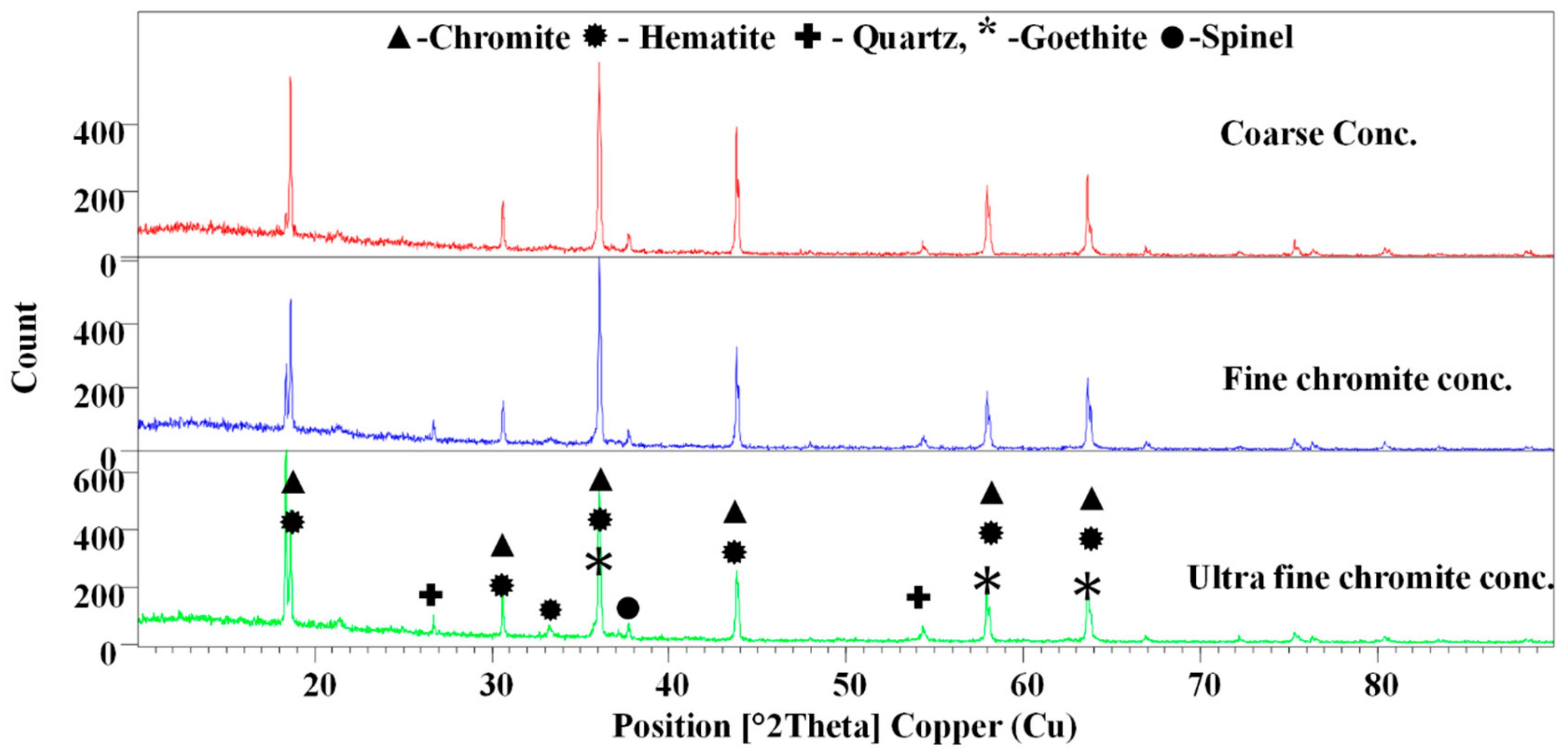
3.1.2. X-ray Diffraction Analysis

The XRD analysis results (Figure 2) shows that the samples contain mainly chromite magnesian (Al0.06Cr1.64Fe0.78Mg0.5O4Ti0.02), hematite (Fe2O3), goethite (FeO(OH)), spinel (MgAl2O4) and quartz(SiO2).

3.1.3. Heavy Liquid Separation Tests

Heavy-liquid separation studies were carried out by using organic liquids to analyze the liberation of mineral grains of the samples. The heavy density separation study was performed by considering two types of density liquids of densities at 2.8 (bromoform) and 3.3 g/cm3 (di-iodo-methane). Results are presented in Table 4. It is evident that the Cr:Fe ratio of the coarse concentrate increased from 2.4 to 2.7. Similarly, the Cr:Fe ratio of the fine and ultrafine concentrates were enhanced from 2.8 and 1.6, to 3.2 and 2.5, respectively. Results also indicate that the liberation of the iron-bearing minerals are significantly increasing when particle size decreases and therefore, the Cr:Fe ratio is enhanced to about 0.9 for the ultrafine size concentrate. Also, this is an indication on the amenability scope for the gravity separation for the removal of the iron-bearing gangue minerals. It can be assumed that by discarding the float parts to the non-magnetic fraction at higher magnetic intensity, the desired Cr:Fe ratio can be achieved.

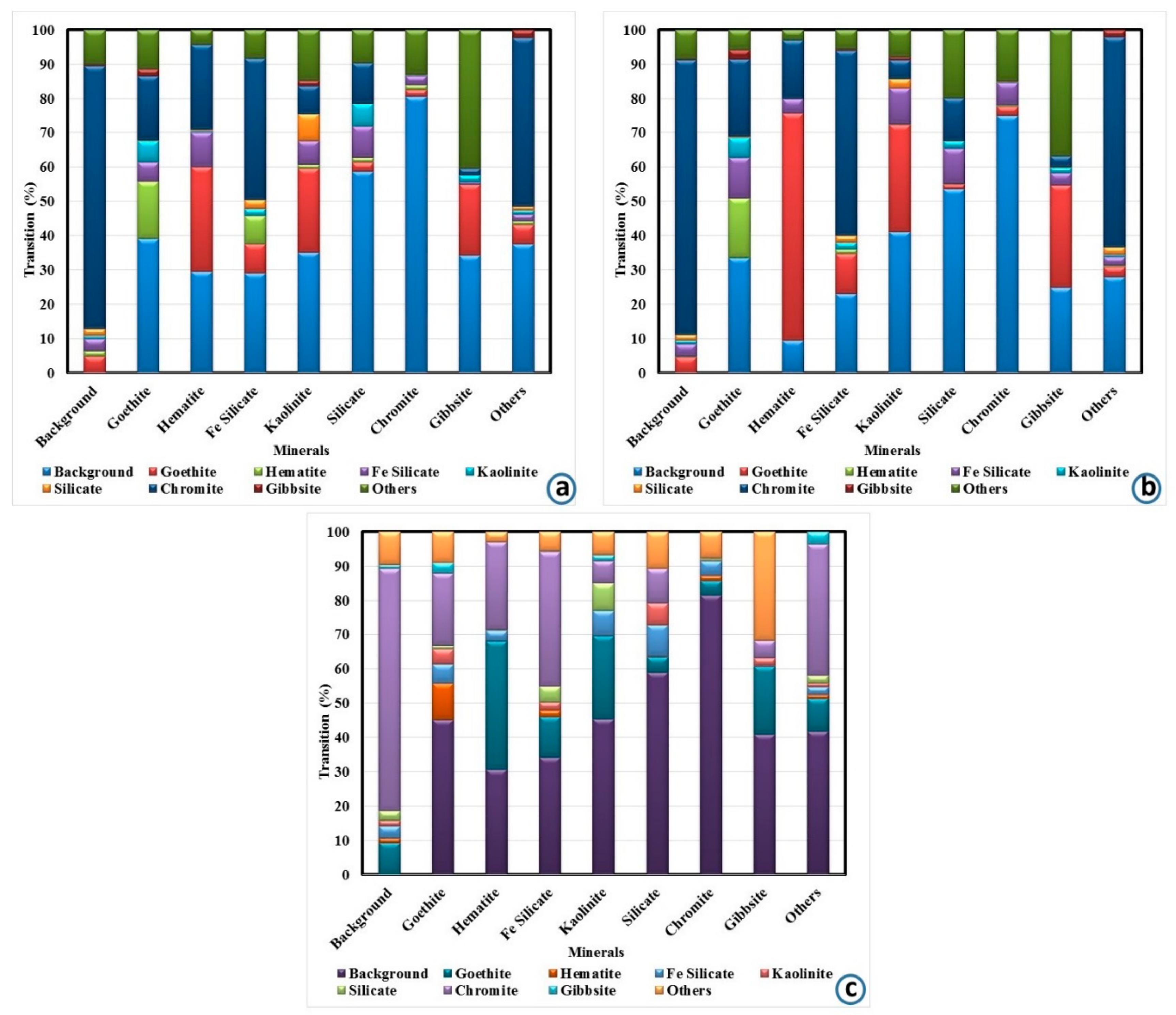
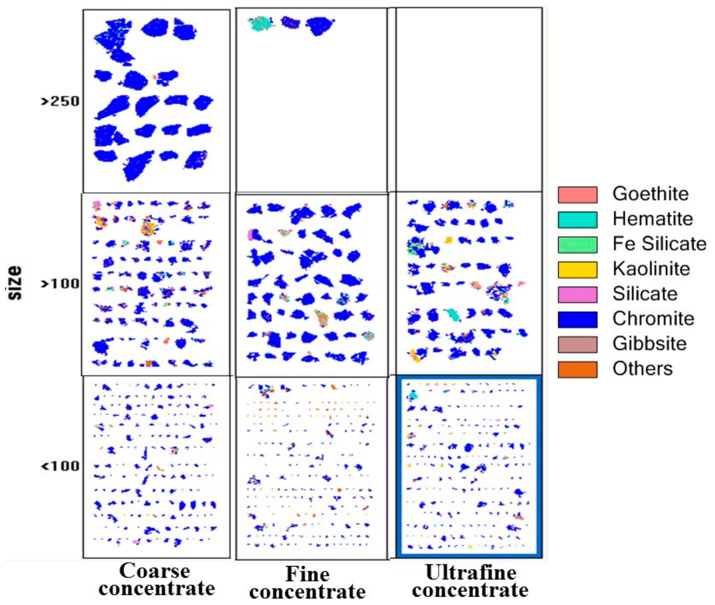
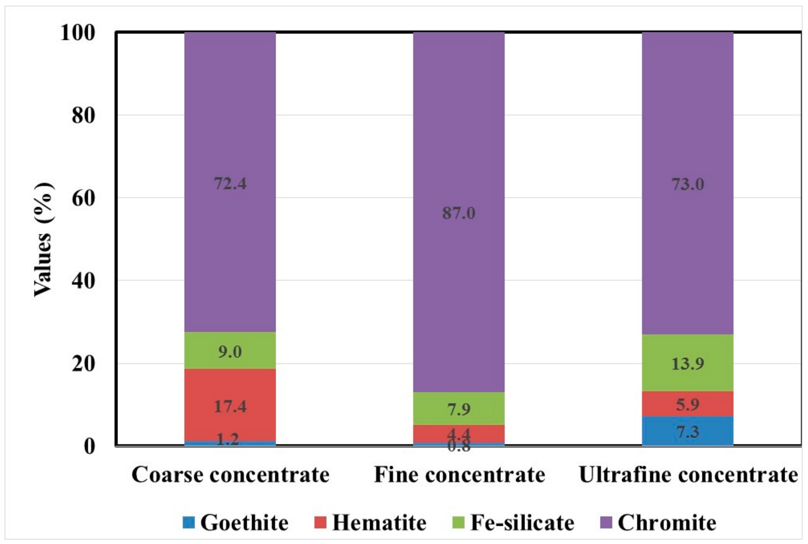
3.1.4. Mineralogical Studies

The polished sections of the samples were studied by QEMSCAN. The results were derived by analyzing more than 8500 particle using five different polished blocks. The mineral composition of the concentrates are shown in Table 5. It can be seen that hematite, goethite, and iron silicates (serpentine, olivine group of minerals) are predominant as iron-bearing gangue minerals along with chromite.
Further, the average liberation grain size of the minerals are also given in Table 5. It is found that the average grain size for chromite and gangue minerals widely varies and the gangue minerals are liberated at a finer size compared to chromite. It is also observed that the gangue minerals are well liberated at ultrafine particle size ranges which indicates the desliming, as well as gravity separation techniques, can be used to separate.
While Figure 3 shows the presence of different minerals interlocked together but it is evident that a substantial amount of chromite is present in free form, as shown by the QEMSCAN images (Figure 4). In fact, 76.8%, 80.1% and 70.7% of the chromite particles are in free form in the coarse, fine, and ultrafine concentrates, respectively (which can be separated). Similarly, the association or interlock of the gangue minerals can be observed in Figure 3. For example, the Fe-silicate particles in the coarse concentrate indicate that 53.9% of the particles are interlocked with the chromite particles. In other words, the separation of Fe-silicate is possible at a higher efficiency due to their different density, but the interlocking of these particles with chromite enhances the apparent particle density and in turn, it minimizes the efficiency of the gravity separation. Similar interpretations are valid for different gangue minerals in these three cases. However, the enhancement of the Cr:Fe ratio due to the separation of liberated gangue particle may not help in decreasing the Fe content to zero. It should be noted that iron is present in the chromite spinel and it cannot be separated. Therefore, the Cr:Fe ratio data may not be helpful in this case. For a better understanding, the deportment of iron was analyzed by QEMSCAN. The elemental deportments for iron (Figure 5) showed that it is reported from hematite, goethite, and Fe-silicates along with chromite. In other words, a higher value of iron might have come from chromite particles as well as from the interlocking of iron-bearing minerals with chromite. This observation has been also reported earlier [9,28,41]. Therefore, the iron level in the concentrate can be lowered to only a certain extent, and beyond that, its separation is not feasible through the beneficiation. From Figure 5, it is observed that 72.4%, 87%, and 73% of the total iron is reported from chromite in the coarse, fine, and ultrafine concentrate, respectively. It is also found that iron is distributed mostly in hematite for the coarse concentrate, whereas Fe-silicate bearing minerals are dominant in the fine and ultrafine concentrate, respectively. It is concluded that the iron content in the beneficiation product can be lowered to 10.4%, 11.6%, and 13.2% for the coarse, fine, and ultrafine concentrate, respectively. Beyond these points, the iron content cannot be decreased further without losing chromite particles.
From the automated mineralogy, it is established that the best beneficiation strategy should decrease the hematite content of the coarse concentrate. The amenability of the separation is feasible by the gravity separation as well as magnetic separation. However, the magnetic separation may be more helpful due to the differences in the particle magnetic susceptibility. On the other hand, the gravity separation may be difficult due to the low concentration criterion between the minerals.

3.2. Separation Studies

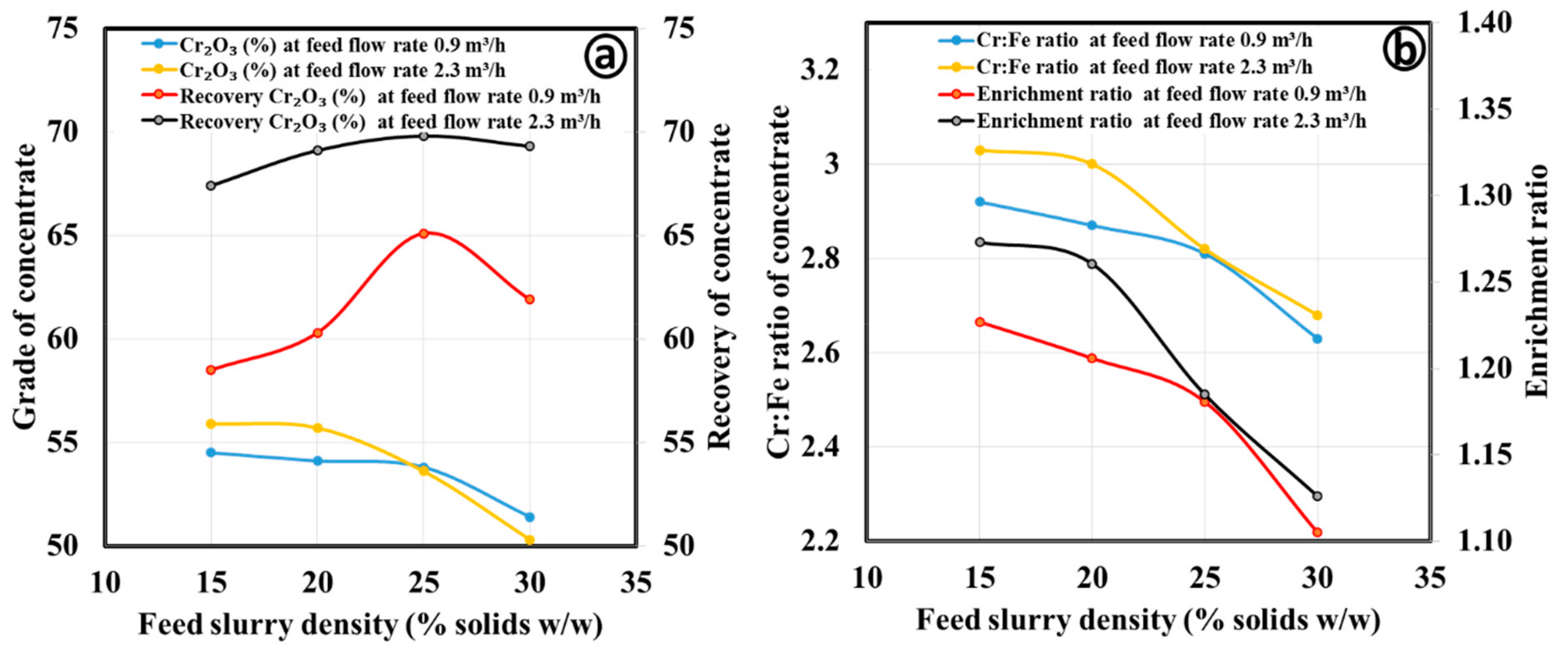
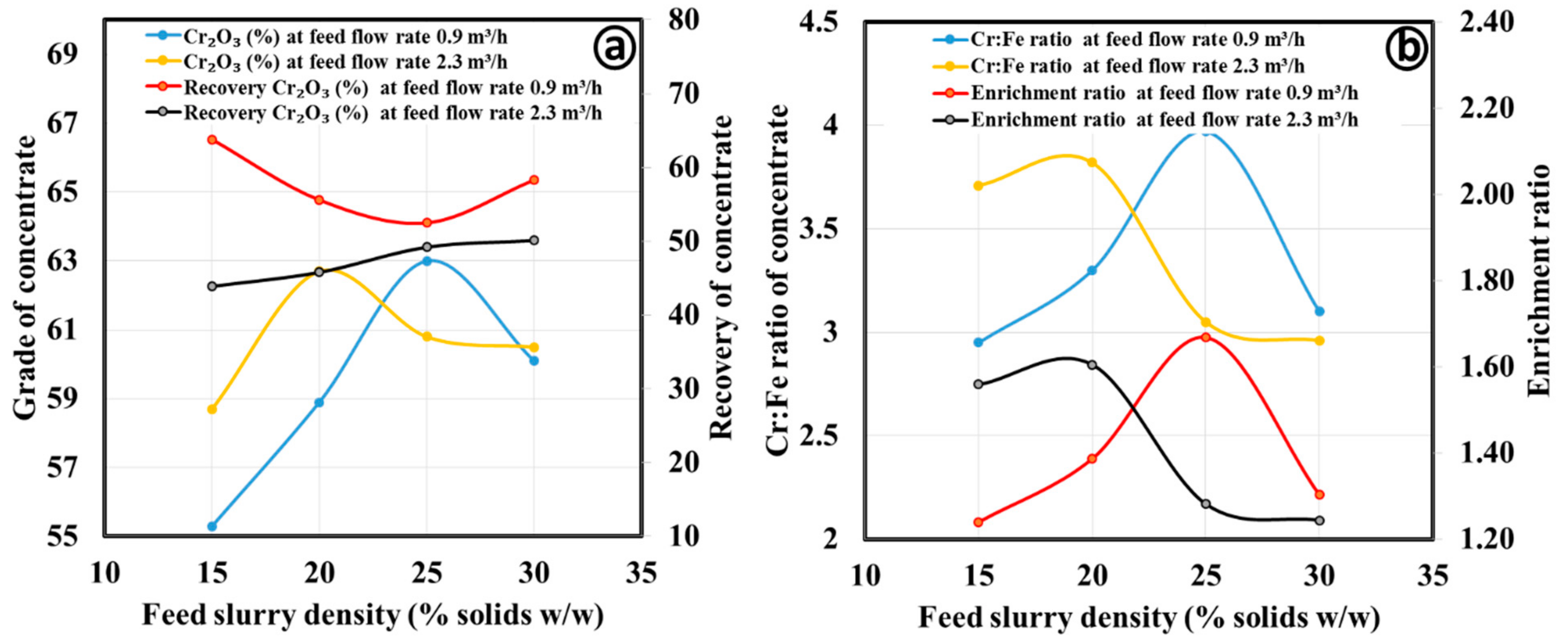
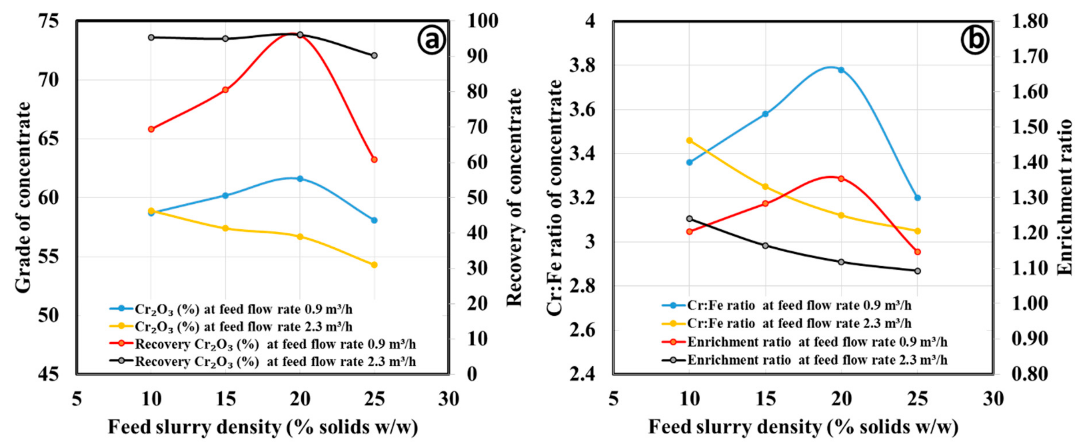
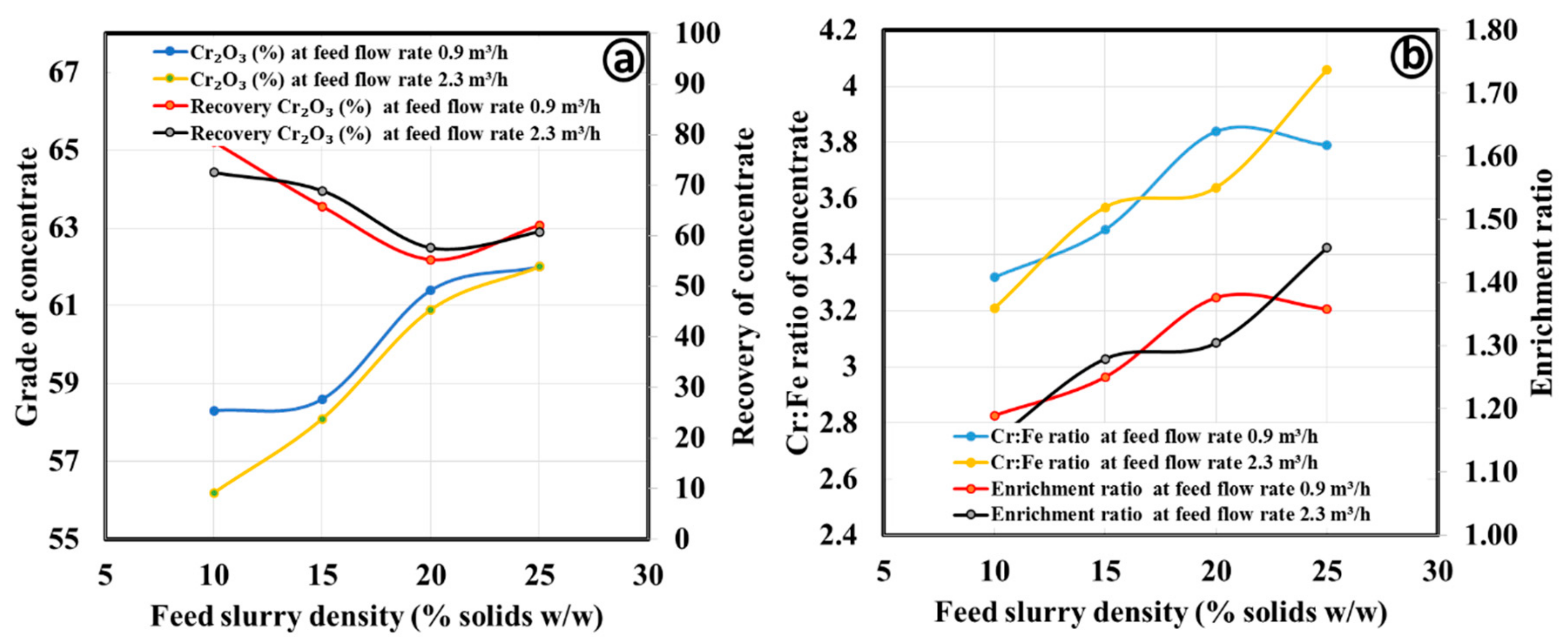
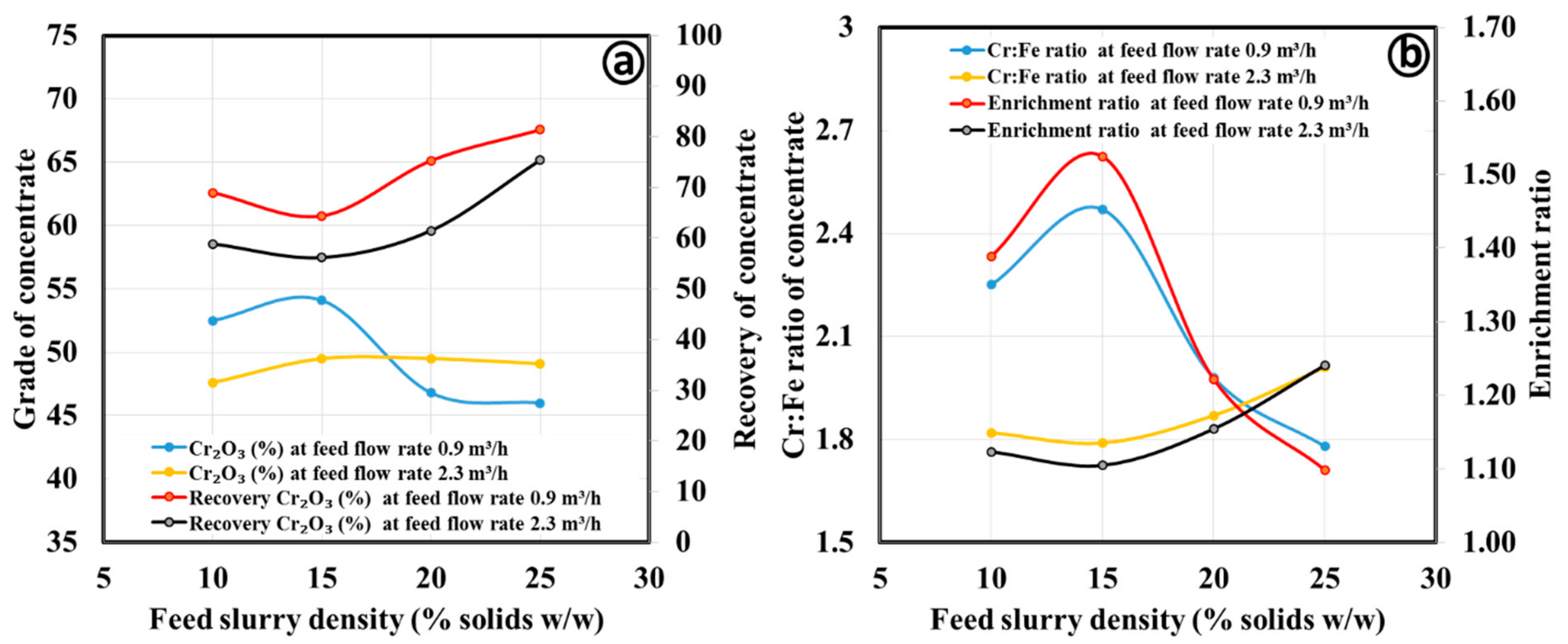
3.2.1. Gravity Separation by Spiral Concentrator

Results of the separation using the FM1 spiral design for the coarse concentrate is shown in Figure 6. From Figure 6a, it is found that the grade of the concentrate decreases with an increase in the slurry pulp density at both slurry flow rates. It is also observed that the separation efficiency is poor with slurry pulp density higher than 20%. The recovery in the concentrate fraction is found to be in reverse trend of the grade, which is a general feature in the separation. Influence of the slurry flow rate also significantly influences the separation, which is evident from both grade and recovery values. A better separation is observed for the higher slurry flow rate of 2.3 m3/h. A similar observation has been reported for other spiral designs for treating low-grade chromite and hematite ores [10,11,42]. The separation efficiency improves with increasing the feed velocity due to the enhancement of the centrifugal force acting on the particles. This, results in migration of coarser gangue particles (iron silicate bearing minerals) to the peripheral tailing stream. The influence of the slurry density, as well as flow rate on the separation, is analyzed in terms of Cr:Fe and enrichment ratio to understand the rejection of iron-bearing gangue minerals (Figure 6b). However, the rejection of iron-bearing gangue minerals is drastically affected with an increase in the slurry pulp density, but the separation is favorable at a higher slurry flow rate.
Similar tests were carried out in the HG10i spiral concentrator for the coarse concentrate sample. From Figure 7a, it is found that the optimum separation (grade) is at a pulp density of more than 20%. The layer of particles governs the separation inside the trough flows over the surface, which is dictated by the slurry flow rate as well as slurry density. The influence of slurry density on the coarse particle recovery is well explained in the literature [43,44]. However, the influence of the wash water flow rate is more of an influence than slurry density, which is not considered in the present research. It is also found that the grade, as well as the iron rejection, is better in the HG10i design. The lower diameter trough with a minimum pitch in the design facilitated the enhanced separation and resulted in Cr:Fe ratio values of more than 4 (Figure 7b).
Separation studies using fine concentrate samples were carried out in the spirals by varying slurry flow rate and pulp density. The results of the separation using FM1 spiral design is shown in Figure 8. From the Figure 8a, it is found that the grade of the concentrate increases with an increase in slurry pulp density up to 20% solids and after that, it decreases at the low slurry flow rate. The grade decreases with an increase of slurry density at the higher slurry flow rate. The Cr2O3 grade of the concentrate was enriched to values above 60% at the lower slurry flow rate. This is basically due to the better liberation of the chromite particles in the feed slurry along with a single layer of particle flow which enhances the separation. This in turn, results in better segregation of the heavy particles in the concentrate. Further, influence of the slurry density, as well as the flow rate on the separation was analyzed in terms of the Cr:Fe and enrichment ratios to understand the rejection of the iron-bearing gangue minerals. Results in Figure 8b shows that rejection of iron-bearing gangue minerals drastically decreases with an increase in slurry pulp density at the higher slurry flow rate. However, the separation is favorable at a lower slurry flow rate.
Figure 9 presents the results of similar tests carried out in the HG10i spiral design. Figure 9a indicates that the Cr2O3 grade of the concentrate increases with an increases in slurry pulp density at both flow rates. The optimum separation (grade) is also obtained at a pulp density of 25%. Generally, the separation inside the trough is governed by the layer of particles flows over the surface along with the hindered settling phenomena which enhances the separation based on the settling ratio of the heavy and light density particles. Similar to the coarse concentrate, the grade as well as iron rejection, were found to be better in the HG10i type. However, the recovery for both flow rates is below 70% while achieving a Cr2O3 grade higher than 60%. The Cr:Fe and enrichment ratios are found to be increasing as the slurry pulp density increases. The maximum Cr:Fe and enrichment ratios are observed for the higher slurry flow rate of 2.3 m3/h (Figure 9b).
Results of the Cr2O3 upgradation using the FM1 spiral design are shown in Figure 10. From Figure 10a, it is found that the Cr2O3 grade of the concentrate increases with an increase in slurry pulp density up to 15% in both flow rates. The Cr2O3 grade of the concentrate was enriched but it does not exceed 55%. At the higher slurry flow rate, the grade does not exceed 50%. This is basically due to the entrainment of ultrafine gangue minerals to the concentrate flow. The change in the recovery during the separation is found to be the reverse trend of the grade, and the recovery is higher at lower slurry flow rates. Further, the influence of slurry density, as well as flow rate on the separation were analyzed in terms of Cr:Fe and enrichment ratios to understand the rejection of the iron-bearing gangue minerals. The rejection of iron-bearing gangue minerals is found to be proportional to the grade, but the separation is better at a lower slurry flow rate and pulp density of 15% (Figure 10b).
Figure 11 presents the results of similar tests carried out on the HG10i spiral design. Figure 11a indicates that the Cr2O3 grade of the concentrate increases with an increase in slurry pulp density up to 20%, and it decreases after that. However, there is insignificant change by varying the pulp density at higher flow rates. The recovery of Cr2O3 in the concentrate is found to be less than 40% in all tests. Therefore, the main disadvantage of this design is inadequate segregation of the ultrafine chromite particles. This is basically due to the inferior displacement of the particles radially due to the higher viscosity of the slurry. The Cr:Fe and enrichment ratios (Figure 11b) are also increasing when the slurry pulp density increases to 20%, and after that it decreases. The maximum Cr:Fe and enrichment ratio values are observed for the higher slurry flow rate of 2.3 m3/h.

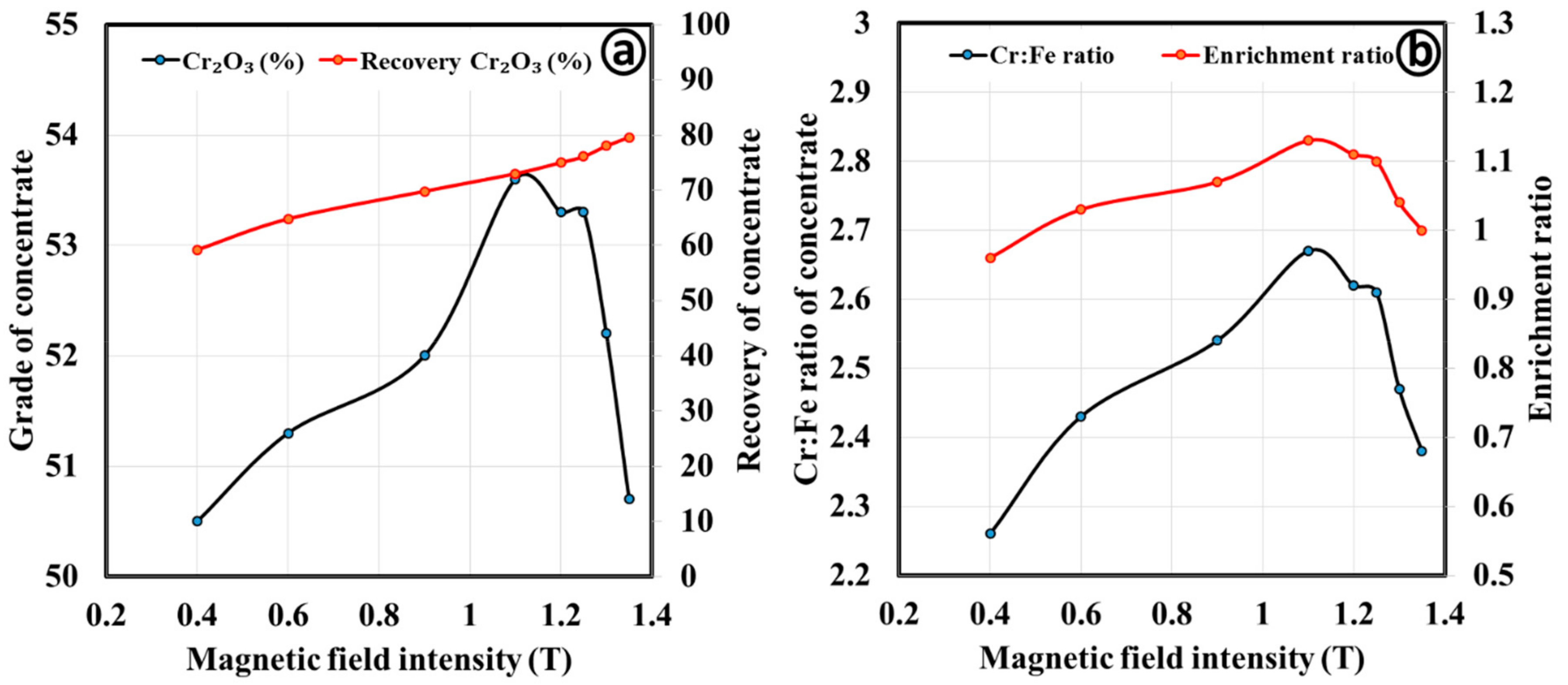
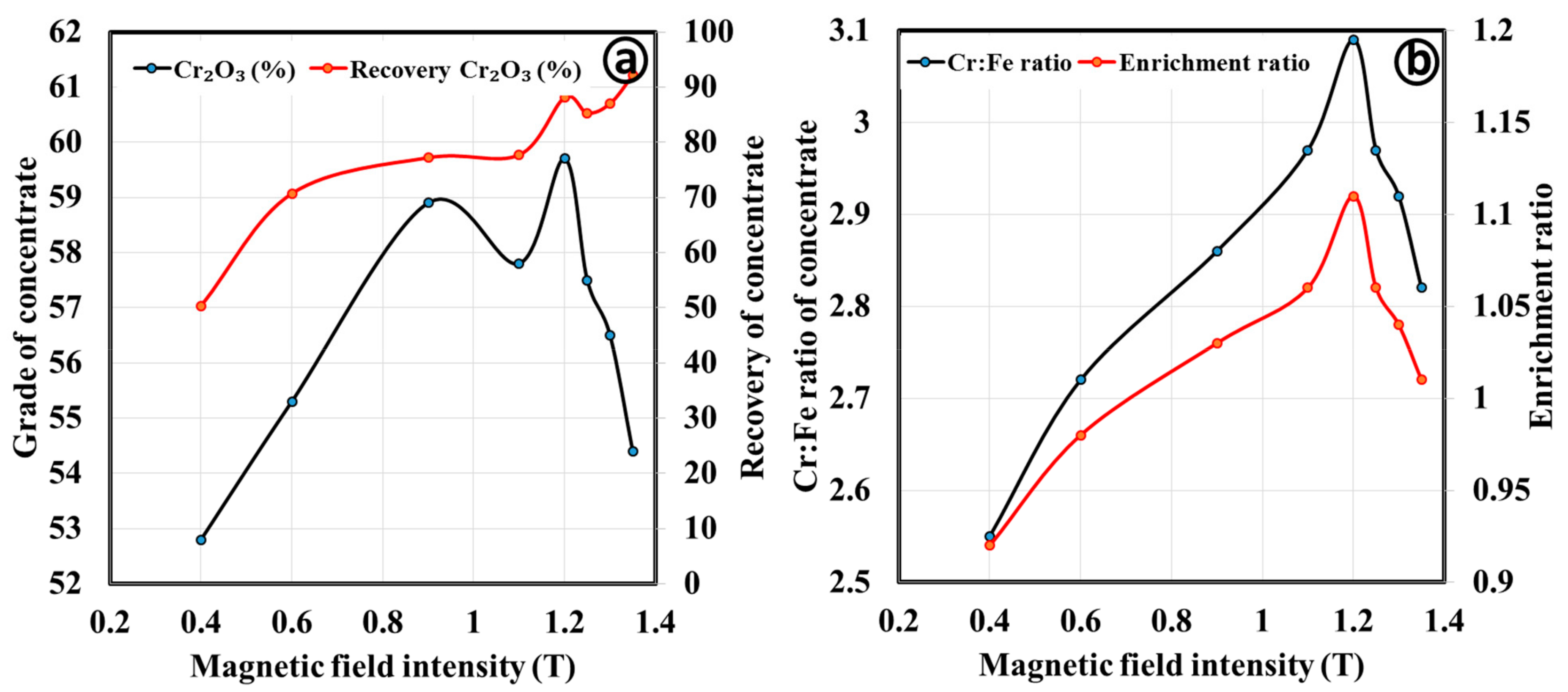
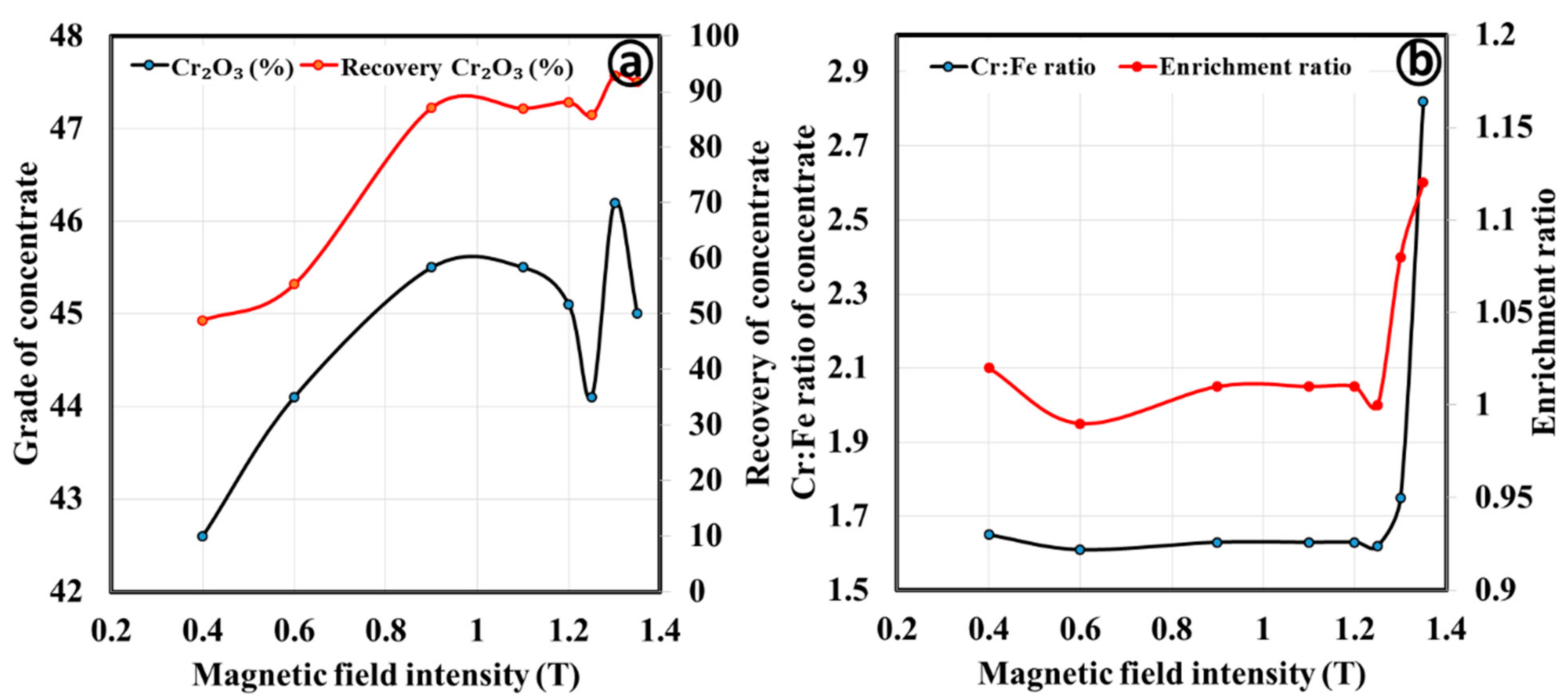
3.2.2. Magnetic Separation by Wet High Intensity Magnetic Separator
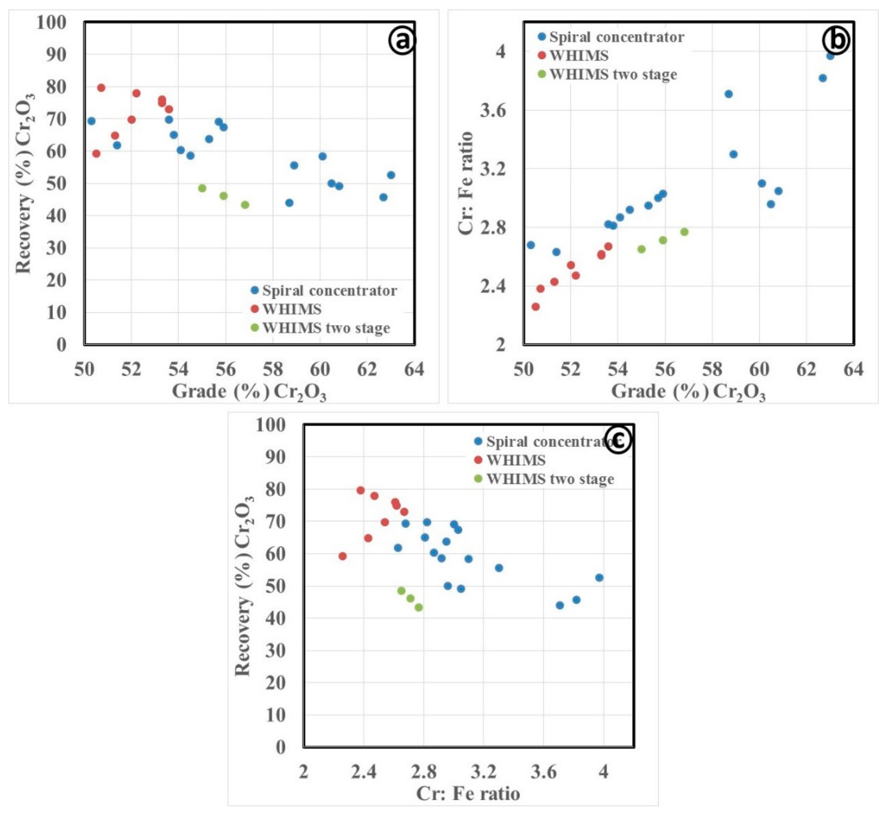
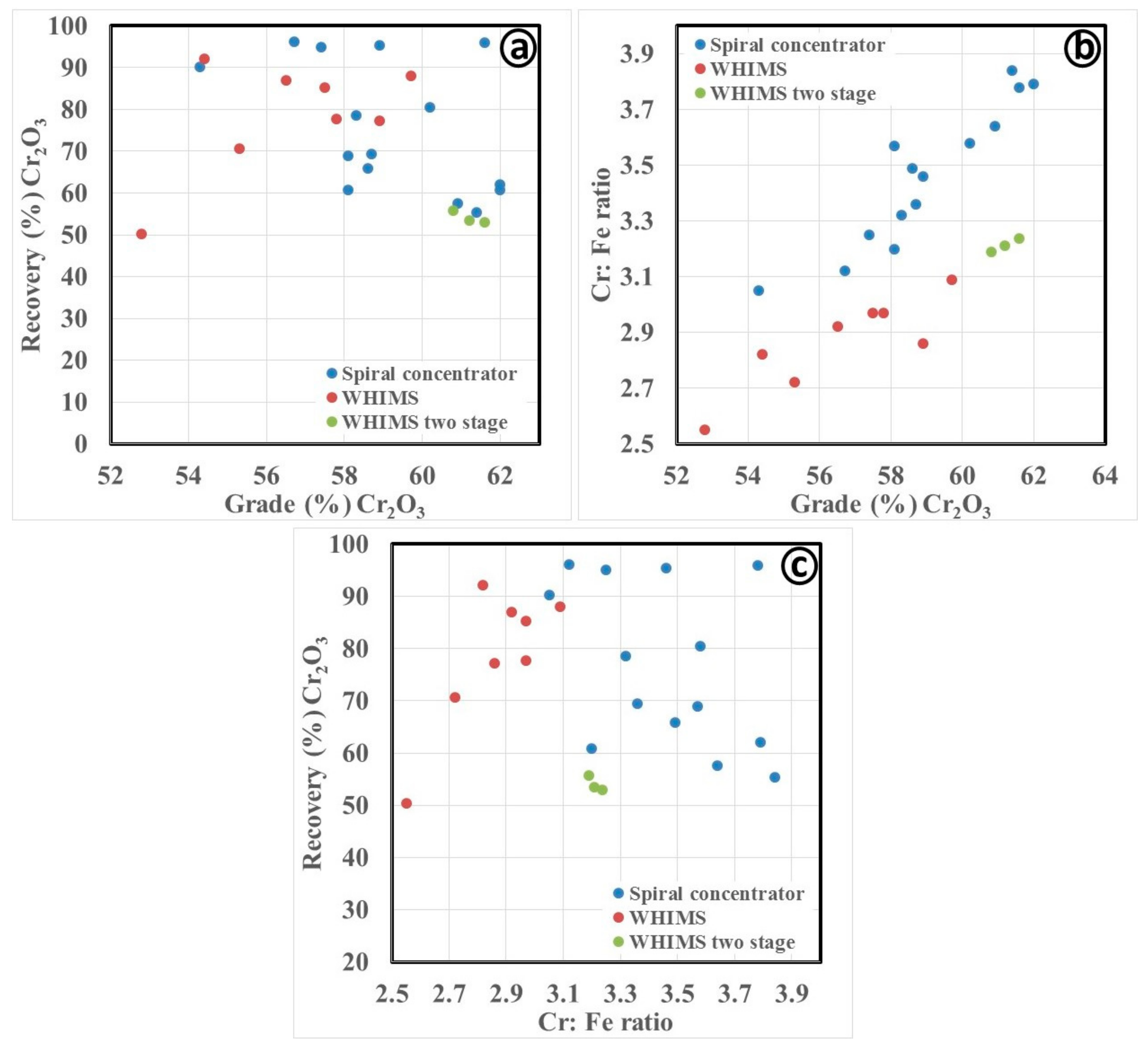
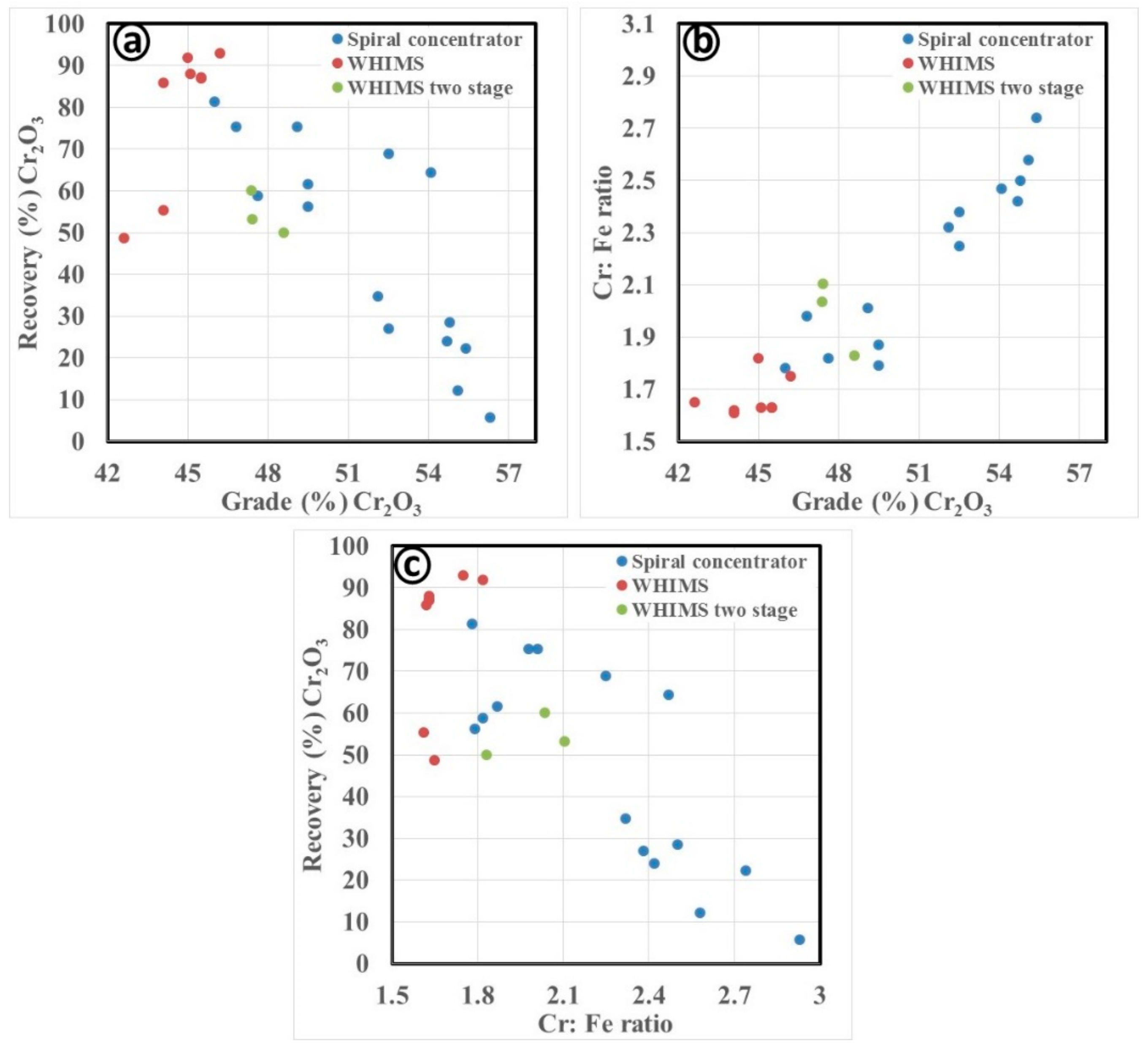
Magnetic separation in WHIMS was carried out by varying the magnetic field intensity from 0.4 to 1.3 T. Figure 12a shows that there is an increase in the grade of the magnetic fraction of the coarse concentrate with an increase in magnetic field intensity up to 1.1T, and it decreases drastically after that. This is due to the paramagnetic nature of the chromite and rejection of the silicate bearing gangue minerals in the non-magnetic fraction. However, at a magnetic field intensity of 1.3 T, there may be the attraction of goethite and iron-silicate bearing minerals which are paramagnetic and are reported to the magnetic fraction. Similarly, the iron rejection and the efficiency of separation with the change in the magnetic field intensity is shown in Figure 12b. The separation of iron-bearing minerals from chromite is found to be limited as the Cr:Fe ratio of the product is below 2.7. This is due to the abundance of the near magnetic susceptibility minerals as well their poor liberation.
Similarly, the results for the fine and ultrafine concentrates are given in Figure 13 and Figure 14. Figure 13 shows separation of chromite, as well as the rejection of iron-bearing minerals at a magnetic field intensity of 1.2 T. Further, the Cr2O3 grade of the magnetic fraction is enriched to 59.7% from 53.7% in the feed. The Cr-Fe ratio was also increased from 2.8 to 3.94.
The maximum achievable Cr2O3 grade for the ultrafine concentrate is 45% from a feed with 42.9% Cr2O3 (Figure 14), with enhancement of the Cr:Fe ratio from 1.6 to 1.8. The maximum grade is reported at a magnetic field intensity of 0.9 T. The separation of the iron-bearing particles is found to be minimal for the ultrafine concentrate compared to other two samples. This is mainly due to inefficient capture of the magnetic particles at finer particle size range as well as the abundance of hematite and goethite in the sample which are paramagnetic and are reported along with chromite.

3.3. Discussion

From Figure 15, it is observed that the WHIMS can be used for increasing chromium oxide recovery, but it does not result in a significant Cr2O3 grade and Cr:Fe ratio. Further, the two-stage separation was adopted to discard hematite and goethite at a lower magnetic field intensity of 0.4 T and iron-bearing silicates at 1.2 T. The two-stage separation for such low-grade ferruginous chromite ore is well reported in the literature [13]. The results of the two-stage separation are found to be insignificant as there is an incremental change in the grade, but the recovery decreases drastically. However, the spiral concentrator can be used to achieve products with a Cr:Fe ratio higher than 2.8, and recovery level at 70%. In the case of the fine concentrate sample, the grade–recovery relationship (Figure 16a) is found to be identical in both units. However, the enhancement of the Cr:Fe ratio is weak in the WHIMS, compared to the spiral separator (Figure 16b,c). This is due to the efficient separation of the non-magnetic gangue minerals (e.g., iron-bearing silicates, quartz) from chromite whereas an inefficient separation of hematite and goethite. Chromite has been previously separated at magnetic field intensities above 1 T by discarding the gangue minerals (serpentine and olivine, which associate with chromite) [32]. This is possible since chromite has slightly more magnetic susceptibility than gangue minerals due to its higher iron content. The major gangue minerals in our case are hematite and goethite along with the silicate bearing phases which hindered the efficient separation as their magnetic susceptibility are similar. The trend of correlation for the separation for ultrafine concentrate (Figure 17) is found to be identical with the coarse concentrate. In all samples, the spiral concentrate is found to be more efficient for the enhancement of the Cr:Fe ratio compared to the WHIMS. Also, it is evident that the separation is primarily influenced by the spiral design.
The optimum conditions derived from the spiral concentrator is given in Table 6. The Cr:Fe ratio of the fine concentrate is upgraded from 2.38 to 3.97 with a Cr2O3 grade of 63% and recovery of 52.5% in the HG10i spiral. Upgradation of the Cr:Fe ratio with higher recovery is possible with two-stage separation. Similarly, the Cr:Fe ratio of the fine concentrate was upgraded from 2.79 to 4.06, with a Cr2O3 grade of 62.0% and 52.6% recovery. Optimum condition was obtained at a feed rate of 2.3 m3/h and pulp density of 25% in HG10i spiral. Also, a higher Cr:Fe ratio was achieved in the FM1 design (3.78 vs. 2.79) with a Cr2O3 grade of 61.6% and mass recovery of 83.7% at a feed rate of 0.9 m3/h and pulp density of 20%. The lower feed flow rate is favorable while separating the ultrafine particles of less than 45 µm [10]. Further upgradation the Cr:Fe ratio is possible with two stages of separation with a combination of these two spiral designs. The Cr:Fe ratio of the ultrafine concentrate was upgraded to 2.47 from 1.62 with a Cr2O3 grade of 54.1% and 51.1% recovery. This was achieved at a feed rate of 0.9 m3/h and pulp density of 15% in the FM1 spiral.
The optimum conditions for the two-stage separation in WHIMS are given in Table 7, Table 8 and Table 9. The Cr:Fe ratio of the coarse concentrate was upgraded to 2.62 from 2.38 with a Cr2O3 grade of 53.3% and mass recovery of 70.3%. Further upgradation the Cr:Fe ratio is possible to 2.77 with a mass recovery of 38.1% and Cr2O3 grade of 56.8% with two-stage separation. Similarly, Table 8 shows that the Cr:Fe ratio of the fine concentrate was upgraded to 3.09 from 2.79 with a Cr2O3 grade of 59.7% and mass recovery of 79.3%. Further upgradation of Cr:Fe ratio is possible to 3.24 with a mass recovery of 46.1% and Cr2O3 grade of 61.6% with two-stage separation. The Cr:Fe ratio of the ultrafine concentrate was upgraded to 1.81 from 1.62 with a Cr2O3 grade of 45% and yield of 87.4% (Table 9). Further upgradation of the Cr:Fe ratio is possible to 2.11 with a yield of 48.1% and Cr2O3 grade of 47.4% with the two-stage separation.

4. Conclusions

The chromite fine particles generated from a gravity-based beneficiation plant was reprocessed using gravity (spiral concentrator) and magnetic separation (WHIMS) to enhance the Cr:Fe ratio. Initially, a detailed mineralogical characterization was carried out to evaluate the feasibility of the separation process. The Cr:Fe ratio of the fine concentrate sample was found to be higher compared to the other two samples (i.e., 2.8 compared to 2.4 and 1.6 for the coarse and ultrafine concentrates, respectively). It was also found that the Cr2O3 content is more segregated at the intermediate size fraction in all samples. XRD data revealed the abundance of iron-bearing minerals (goethite, hematite) and quartz along with chromite. QEMSCAN also showed that 76.8%, 80.1%, and 70.7% of the chromite particles are liberated in the coarse, fine, and ultrafine concentrates, respectively. About 72.4%, 87%, and 73% of the total iron was also found to be reported from chromite in the coarse, fine, and ultrafine concentrates, respectively.
Separation of the iron-bearing gangue minerals was found to be more efficient using gravity concentration rather than magnetic separation. It was also found that the spiral design plays an important role on the efficient chromite segregation. The HG10i model was found to be effective for the separation of chromite in processing coarse and fine concentrate samples, whereas FM1 was found to be suitable for the ultrafine concentrate sample. The Cr:Fe ratio of the coarse, fine, and ultrafine concentrate samples was enhanced to 3.97, 4.06, and 2.47, respectively, via gravity separation. Further upgradation of the Cr:Fe ratio is possible with two or three stages of separation using this type of spiral designs. Also, the recovery values may be further enhanced by recirculating the middling fractions of the spiral concentrator, as well as optimizing the multistage separation in a rougher–scavenger–cleaner circuit. In addition, future studies can focus on the influence of wash water with different trough design or number of troughs, along with other process variables affecting the separation performance. It is also worth suggesting a detailed investigation of enhancing the Cr:Fe ratio of the chromite ore by treatment in the recently developed enhanced gravity separators (e.g., water only cyclone, multi-gravity separator, knelson concentrator, and falcon concentrator).

Author Contributions

For research articles with several authors, a short paragraph specifying their individual contributions must be provided. The following statements should be used “conceptualization, S.K.T and Y.R.M; methodology, S.K.T.; software, V.S.; validation, S.K.T., Y.R.M. and V.S.; formal analysis, S.K.T.; investigation, S.K.T. and Y.R.M.; resources, S.K.T.; data curation, S.K.T.; writing—original draft preparation, S.K.T.; writing—review and editing, S.F., L.O.F.; visualization, S.F.; supervision, L.O.F.; project administration, S.K.T.; funding acquisition, S.K.T.”, please turn to the CRediT taxonomy for the term explanation. Authorship must be limited to those who have contributed substantially to the work reported.

Funding

This research received no external funding.

Acknowledgments

The authors are thankful to the management of Tata Steel Ltd. for the support and permission to publish this study. SKT would like to acknowledge Labex Resources21 supported by the French National Research Agency through the national program “Investissements d’Avenir” [reference ANR–10–LABX–21] for his fellowship.

Conflicts of Interest

The authors declare no conflict of interest.

References

  1. Azari, J. Effect of Chrome ore Qulaity on Ferrochrome Production Efficiency. In Proceedings of the Tenth International Ferroalloys Congress, Cape Town, South Africa, 1—4 February 2004. [Google Scholar]
  2. Dwarapudi, S.; Tathavadkar, V.; Rao, B.C.; Kumar, T.K.S.; Ghosh, T.K.; Denys, M. Development of Cold Bonded Chromite Pellets for Ferrochrome Production in Submerged Arc Furnace. ISIJ Int. 2013, 53, 9–17. [Google Scholar] [CrossRef]
  3. Nurjaman, F.; Subandrio, S.; Ferdian, D.; Suharno, B. Effect of basicity on beneficiated chromite sand smelting process using submerged arc furnace. AIP Conf. Proc. 2018, 1964, 020009. [Google Scholar]
  4. Murthy, Y.R.; Tripathy, S.K.; Kumar, C.R. Chrome ore beneficiation challenges & opportunities–A review. Miner. Eng. 2011, 24, 375–380. [Google Scholar]
  5. Nafziger, R.H. A review of the deposits and beneficiation of lower-grade chromite. J. S. Afr. Inst. Min. Metall. 1982, 82, 205–226. [Google Scholar]
  6. Atalay, U.; Özbayoğlu, G. Beneficiation and agglomeration of chromite—It’s application in Turkey. Miner. Process. Extr. Metall. Rev. 1992, 9, 185–194. [Google Scholar] [CrossRef]
  7. Das, A.; Sarkar, B. Advanced gravity concentration of fine particles: A review. Miner. Process. Extr. Metall. Rev. 2018, 39, 359–394. [Google Scholar] [CrossRef]
  8. Tripathy, S.K.; Murthy, Y.R.; Singh, V. Characterisation and separation studies of Indian chromite beneficiation plant tailing. Int. J. Miner. Process. 2013, 122, 47–53. [Google Scholar] [CrossRef]
  9. Tripathy, S.K.; Banerjee, P.; Suresh, N. Magnetic separation studies on ferruginous chromite fine to enhance Cr: Fe ratio. Int. J. Miner. Metall. Mater. 2015, 22, 217–224. [Google Scholar] [CrossRef]
  10. Tripathy, S.K.; Murthy, Y.R. Modeling and optimization of spiral concentrator for separation of ultrafine chromite. Powder Technol. 2012, 221, 387–394. [Google Scholar] [CrossRef]
  11. Tripathy, S.K.; Murthy, Y.R. Multiobjective optimisation of spiral concentrator for separation of ultrafine chromite. Int. J. Min. Miner. Eng. 2012, 4, 151–162. [Google Scholar] [CrossRef]
  12. Sunil, K.T.; Rama, M.Y.; Tathavadkar, V.; Mark, B.D. Efficacy of multi gravity separator for concentrating ferruginous chromite fines. J. Min. Metall. Min. 2012, 48, 39–49. [Google Scholar]
  13. Tripathy, S.K.; Murthy, Y.R.; Singh, V.; Suresh, N. Processing of Ferruginous Chromite Ore by Dry High-Intensity Magnetic Separation. Miner. Process. Extr. Metall. Rev. 2016, 37, 196–210. [Google Scholar] [CrossRef]
  14. Özgen, S. Modelling and optimization of clean chromite production from fine chromite tailings by a combination of multigravity separator and hydrocyclone. J. S. Afr. Inst. Min. Metall. 2012, 112, 387–394. [Google Scholar]
  15. Öztürk, F.D.; Temel, H.A. Beneficiation of Konya-Beyşehir Chromite for Producing Concentrates Suitable for Industry. JOM 2016, 68, 2449–2454. [Google Scholar] [CrossRef]
  16. Çiçek, T.; Cengizler, H.; Cöcen, İ. An efficient process for the beneficiation of a low grade chromite ore. Miner. Process. Extr. Metall. 2010, 119, 142–146. [Google Scholar] [CrossRef]
  17. Özgen, S. Clean chromite production from fine chromite tailings by combination of Multi Gravity Separator and Hydrocyclone. Sep. Sci. Technol. 2012, 47, 1948–1956. [Google Scholar] [CrossRef]
  18. Singh, R.K.; Dey, S.; Mohanta, M.K.; Das, A. Enhancing the Utilization Potential of a Low Grade Chromite Ore through Extensive Physical Separation. Sep. Sci. Technol. 2014, 49, 1937–1945. [Google Scholar] [CrossRef]
  19. Can, İ.B.; Özsoy, B.; Ergün, Ş.L. Developing an optimum beneficiation route for a low-grade chromite ore. Physicochem. Probl. Miner. Process. 2019, 55, 865–878. [Google Scholar]
  20. Tripathy, S.K.; Ramamurthy, Y.; Singh, V. Recovery of chromite values from plant tailings by gravity concentration. J. Miner. Mater. Charact. Eng. 2011, 10, 13. [Google Scholar] [CrossRef]
  21. Akar Sen, G. Application of Full Factorial Experimental Design and Response Surface Methodology for Chromite Beneficiation by Knelson Concentrator. Minerals 2016, 6, 5. [Google Scholar] [CrossRef]
  22. Çiçek, T.; Cöcen, I.; Engin, V.T.; Cengizler, H.; Şen, S. Technical and economical applicability study of centrifugal force gravity separator (MGS) to Kef chromite concentration plant. Miner. Process. Extr. Metall. 2008, 117, 248–255. [Google Scholar] [CrossRef]
  23. Tripathy, S.K.; Bhoja, S.K.; Murthy, Y.R. Processing of chromite ultra-fines in a water only cyclone. Int. J. Min. Sci. Technol. 2017, 27, 1057–1063. [Google Scholar] [CrossRef]
  24. Aslan, N. Application of response surface methodology and central composite rotatable design for modeling and optimization of a multi-gravity separator for chromite concentration. Powder Technol. 2008, 185, 80–86. [Google Scholar] [CrossRef]
  25. Foucaud, Y.; Dehaine, Q.; Filippov, L.O.; Filippova, I.V. Application of Falcon Centrifuge as a Cleaner Alternative for Complex Tungsten Ore Processing. Minerals 2019, 9, 448. [Google Scholar] [CrossRef]
  26. Farrokhpay, S.; Filippov, L.; Fornasiero, D. Pre-concentration of nickel in laterite ores using physical separation methods. Miner. Eng. 2019, 141, 105892. [Google Scholar] [CrossRef]
  27. Altın, G.; İnal, S.; Alp, İ. Recovery of Chromite from Processing Plant Tailing by Vertical Ring and Pulsating High-Gradient Magnetic Separation. MT Bilimsel 2018, 13, 23–35. [Google Scholar]
  28. Ayinla, K.I.; Baba, A.A.; Tripathy, B.C.; Ghosh, M.K.; Dwari, R.K.; Padhy, S.K. Enrichment of a Nigerian chromite ore for metallurgical application by dense medium flotation and magnetic separation. Metall. Res. Technol. 2019, 116, 324. [Google Scholar] [CrossRef]
  29. Subandrio, S.; Dahani, W.; Alghifar, M.; Purwiyono, T.T. Enrichment Chromite Sand Grade Using Magnetic Separator. IOP Conf. Ser. Mater. Sci. Eng. 2019, 588, 012033. [Google Scholar] [CrossRef]
  30. Gupta, P.; Bhandary, A.K.; Chaudhuri, M.G.; Mukherjee, S.; Dey, R. Kinetic Studies on the Reduction of Iron Oxides in Low-Grade Chromite Ore by Coke Fines for Its Beneficiation. Arab. J. Sci. Eng. 2018, 43, 6143–6154. [Google Scholar] [CrossRef]
  31. Tripathy, S.K.; Singh, V.; Ramamurthy, Y. Improvement in Cr:Fe Ratio of Indian Chromite Ore for Ferro Chrome Production. Int. J. Min. Eng. Miner. Process. 2012, 1, 101–106. [Google Scholar]
  32. Güney, A.; Onal, G.; Çelik, M.S. A new flowsheet for processing chromite fines by column flotation and the collector adsorption mechanism. Miner. Eng. 1999, 12, 1041–1049. [Google Scholar] [CrossRef]
  33. Ucbas, Y.; Bozkurt, V.; Bilir, K.; Ipek, H. Concentration of chromite by means of magnetic carrier using sodium oleate and other reagents. Physicochem. Probl. Miner. Process. 2014, 50, 767–782. [Google Scholar]
  34. Ucbas, Y.; Bozkurt, V.; Bilir, K.; Ipek, H. Separation of Chromite from Serpentine in Fine Sizes using Magnetic Carrier. Sep. Sci. Technol. 2014, 49, 946–956. [Google Scholar] [CrossRef]
  35. Gallios, G.P.; Deliyanni, E.A.; Peleka, E.N.; Matis, K.A. Flotation of chromite and serpentine. Sep. Purif. Technol. 2007, 55, 232–237. [Google Scholar] [CrossRef]
  36. Seifelnasr, A.A.; Tammam, T. Flotation behavior of Sudanese chromite ores. J. Eng. Sci. Fac. Eng. Assiut Univ. 2011, 39, 649–661. [Google Scholar]
  37. Alesse, V.; Belardi, G.; Freund, J.; Piga, L.; Shehu, N. Acidic medium flotation separation of chromite from olivine and serpentine. Min. Metall. Explor. 1997, 14, 26–35. [Google Scholar] [CrossRef]
  38. Güney, A.; Atak, S. Separation of chromite from olivine by anionic collectors. Fizykochem. Probl. Miner. 1997, 31, 99–106. [Google Scholar]
  39. Panda, L.; Banerjee, P.K.; Biswal, S.K.; Venugopal, R.; Mandre, N.R. Modelling and optimization of process parameters for beneficiation of ultrafine chromite particles by selective flocculation. Sep. Purif. Technol. 2014, 132, 666–673. [Google Scholar] [CrossRef]
  40. Devasahayam, S. Predicting the liberation of sulfide minerals using the breakage distribution function. Miner. Process. Extr. Metall. 2015, 36, 136–144. [Google Scholar] [CrossRef]
  41. Das, S.K. Quantitative mineralogical characterization of chrome ore beneficiation plant tailing and its beneficiated products. Int. J. Miner. Metall. Mater. 2015, 22, 335–345. [Google Scholar] [CrossRef]
  42. Dixit, P.; Tiwari, R.; Mukherjee, A.K.; Banerjee, P.K. Application of response surface methodology for modeling and optimization of spiral separator for processing of iron ore slime. Powder Technol. 2015, 275, 105–112. [Google Scholar] [CrossRef]
  43. Dehaine, Q.; Filippov, L.O. Modelling heavy and gangue mineral size recovery curves using the spiral concentration of heavy minerals from kaolin residues. Powder Technol. 2016, 292, 331–341. [Google Scholar] [CrossRef]
  44. Sadeghi, M.; Bazin, C.; Renaud, M. Effect of wash water on the mineral size recovery curves in a spiral concentrator used for iron ore processing. Int. J. Miner. Process. 2014, 129, 22–26. [Google Scholar] [CrossRef]
Figure 1. Particle size distribution of the chromite concentrates.
Minerals 09 00667 g001
Figure 2. XRD pattern of the chromite concentrates.
Minerals 09 00667 g002
Figure 3. Association of different minerals in the chromite concentrate samples: (a) coarse, (b) fine, and (c) ultrafine concentrates.
Minerals 09 00667 g003
Figure 4. The QEMSCAN images of the samples in different size classes.
Minerals 09 00667 g004
Figure 5. The iron deportment in different iron bearing mineral phases of the samples.
Minerals 09 00667 g005
Figure 6. Influence of the feed flow rate and slurry density on the treatment of coarse concentrate by the spiral FM1 design (a) for grade and recovery; (b) for Cr:Fe ratio and enrichment ratio of concentrate.
Minerals 09 00667 g006
Figure 7. Influence of the feed flow rate and slurry density on the treatment of coarse concentrate by the spiral HG10i design (a) for grade and recovery; (b) for Cr:Fe ratio and enrichment ratio of concentrate.
Minerals 09 00667 g007
Figure 8. Influence of the feed flow rate and slurry density on the treatment of fine concentrate by the spiral FM1 design (a) for grade and recovery; (b) for Cr:Fe ratio and enrichment ratio of concentrate.
Minerals 09 00667 g008
Figure 9. Influence of the feed flow rate and slurry density on the performance of spiral design HG10i in treating fine concentrate (a) for grade and recovery; (b) for Cr:Fe ratio and enrichment ratio of concentrate.
Minerals 09 00667 g009
Figure 10. Influence of the feed flow rate and slurry density on the treatment of ultrafine concentrate by the spiral FM1design (a) for grade and recovery; (b) for Cr:Fe ratio and enrichment ratio of concentrate.
Minerals 09 00667 g010
Figure 11. Influence of the feed flow rate and slurry density on the treatment of ultrafine concentrate by the spiral HG10i design (a) for grade and recovery; (b) for Cr:Fe ratio and enrichment ratio of concentrate.
Minerals 09 00667 g011
Figure 12. Influence of the magnetic field intensity on the treating coarse concentrate by the WHIMS (a) for grade and recovery; (b) for Cr:Fe ratio and enrichment ratio of concentrate.
Minerals 09 00667 g012
Figure 13. Influence of the magnetic field intensity on the treating fine concentrate by the WHIMS (a) for grade and recovery; (b) for Cr:Fe ratio and enrichment ratio of concentrate.
Minerals 09 00667 g013
Figure 14. Influence of the magnetic field intensity on the treating ultrafine concentrate by the WHIMS (a) for grade and recovery; (b) for Cr:Fe ratio and enrichment ratio of concentrate).
Minerals 09 00667 g014
Figure 15. Comparison of the performance of the spiral concentrator and the WHIMS in treating coarse concentrate (a) for grade and recovery; (b) for grade and Cr:Fe rato; (c) for Cr:Fe rato and recovery.
Minerals 09 00667 g015
Figure 16. Comparison of the performance of the spiral concentrator and the WHIMS in treating fine concentrate (a) for grade and recovery; (b) for grade and Cr:Fe rato; (c) for Cr:Fe rato and recovery.
Minerals 09 00667 g016
Figure 17. Comparison of the performance of the spiral concentrator and the WHIMS in treating ultrafine concentrate (a) for grade and recovery; (b) for grade and Cr:Fe rato; (c) for Cr:Fe rato and recovery.
Minerals 09 00667 g017
Table 1. The process parameters during the spiral concentrator tests.
ParametersSpiral Design Types
HG10iFM1
Spiral length (m)2.843.12
Trough diameter (mm)580685
Trough height/pitch (mm)350360
Number of turns88
Slurry flow rate (m3/h)0.9–2.30.9 and 2.3
Slurry pulp density (wt.%)20 and 2515, 20, 25, 30
Table 2. Elemental assay of the concentrates.
Sample (Concentrates)Assay (%)
Fe(T)CaOSiO2MgOAl2O3Cr2O3LOICr:Fe Ratio
Coarse 14.40.37.99.39.549.93.82.4
Fine 13.20.33.910.89.253.73.72.8
Ultrafine 18.10.28.87.99.542.94.31.6
Table 3. Size by size elemental assay of the concentrates.
Size Fractions (µm)Cr2O3Fe(T)Cr:Fe Ratio
Coarse concentrate
+7105114.62.4
−710 + 50047.915.32.1
−500 + 25048.315.12.2
−250 + 15051.414.22.5
−150 + 7551.812.12.9
−7550.414.42.4
Fine concentrate
+15051.613.62.6
−150 + 7554.613.12.9
−75 + 4556.412.13.2
−45 + 2555.813.42.8
−2548.322.91.4
Ultrafine concentrate
+15025.619.80.9
−150 + 10032.318.71.2
−100 + 7533.118.61.2
−75 + 4542.616.81.7
−45 + 2551.814.42.5
−2536.225.61.0
Table 4. Results of the heavy liquid separation for chromite concentrates.
ProductMass Split (%)Assay (%) Cr:Fe RatioDistribution (%)
Cr2O3Fe(T)Cr2O3Fe(T)
Coarse concentrate
Density (2.8 g/cm3)
Float7.511.611.30.71.75.9
Sink92.553.014.72.598.394.1
Density (3.3 g/ cm3)
Float12.417.818.70.74.416.1
Sink87.654.413.82.795.683.9
Fine concentrate
Density (2.8 g/ cm3)
Float3.222.949.40.31.411.9
Sink96.854.712.13.198.688.1
Density (3.3 g/ cm3)
Float6.110.733.30.21.215.3
Sink93.956.512.03.298.884.7
Ultrafine concentrate
Density (2.8 g/ cm3)
Float5.69.541.50.21.212.9
Sink94.444.916.71.898.887.1
Density (3.3 g/ cm3)
Float14.310.548.90.13.538.7
Sink85.748.313.02.596.561.3
Table 5. Mineral analysis of the concentrates along with the grain size of different minerals.
MineralsMineral Mass (%) Grain Size (µm)
Coarse ConcentrateFine ConcentrateUltrafine ConcentrateCoarse ConcentrateFine ConcentrateUltrafine Concentrate
Chromite81.089.476.1110.758.542.1
Goethite4.02.57.525.024.918.1
Hematite4.12.34.026.735.920.8
Fe-silicate4.71.85.119.921.014.4
Kaolinite0.60.41.128.727.021.3
Silicate1.00.81.628.636.724.3
Gibbsite0.50.20.728.237.521.2
Others4.12.74.017.525.715.7
Table 6. Results of the optimum condition for enhancing Cr:Fe ratios.
Process ParametersProductsMass Split (%)Cr2O3 (%)Cr:Fe RatioCr2O3 (%) RecoveryEnrichment Ratio
Coarse concentrate
Spiral type: HG10i; Slurry density (wt.%): 25; Slurry flow rate (m3/h); 0.9; Splitter position: 20 cmConcentrate41.663.03.9752.51.67
Middling15.949.42.3415.70.98
Tailing42.637.31.4331.80.60
Fine concentrate
Spiral type: HG10i; Slurry density (wt.%): 25; Slurry flow rate (m3/h); 2.3; Splitter position: 20 cm Concentrate52.662.04.0660.81.46
Middling29.257.63.1731.31.14
Tailing18.223.20.727.80.26
Ultrafine concentrate
Spiral type: FM1; Slurry density (wt.%): 15; Slurry flow rate (m3/h); 0.9; Splitter position: 18 cmConcentrate51.154.12.4764.41.52
Middling24.127.50.9415.50.58
Tailing24.834.91.0520.20.65
Table 7. Results of the two-stage separation in the WHIMS for the coarse concentrate.
Magnetic Field IntensityProductsMass Split (%)Cr2O3 (%)Cr:Fe RatioCr2O3 (%) RecoveryEnrichment Ratio
1.2Magnetic70.353.32.675.01.11
Middling8.346.42.17.70.89
Nonmagnetic21.440.21.817.30.74
0.4Magnetic38.156.82.843.41.17
Middling12.552.742.713.21.12
Nonmagnetic19.746.762.318.50.98
Table 8. Results of the two-stage separation in the WHIMS for the fine concentrate.
Magnetic Field IntensityProductsMass Split (%)Cr2O3 (%)Cr:Fe RatioCr2O3 (%) RecoveryEnrichment Ratio
1.2Magnetic79.359.73.188.11.11
Middling4.048.32.63.60.92
Nonmagnetic16.626.41.48.20.50
0.4Magnetic46.161.63.252.91.16
Middling11.457.63.212.21.14
Nonmagnetic21.856.62.723.00.98
Table 9. Results of the two-stage separation in the WHIMS for the ultrafine concentrate.
Magnetic Field IntensityProductsMass Split (%)Cr2O3 (%)Cr:Fe RatioCr2O3 (%) RecoveryEnrichment Ratio
1.3Magnetic87.445.01.891.81.12
Middling4.137.32.03.61.21
Nonmagnetic8.520.21.14.00.70
0.4Magnetic48.147.42.153.21.30
Middling15.045.31.615.80.99
Nonmagnetic24.340.31.522.80.91

