Article

Recovery and Purification of Tin from Tailings from the Penouta Sn–Ta–Nb Deposit

by
Félix Antonio López
1,*,
Irene García-Díaz
1,
Olga Rodríguez Largo
1,
Francisco García Polonio
2 and
Teresa Llorens
2
1
National Center for Metallurgical Research (CENIM), CSIC, 28040 Madrid, Spain
2
Strategic Minerals Spain S.L., 32558 Penouta, Spain
*
Author to whom correspondence should be addressed.
Minerals 2018, 8(1), 20; https://doi.org/10.3390/min8010020
Submission received: 17 November 2017 / Revised: 22 December 2017 / Accepted: 8 January 2018 / Published: 12 January 2018
(This article belongs to the Special Issue Minerals in Mine Wastes: Contributions to the Circular Economy)

Abstract

:
A concentrate obtained from mining tailings containing mainly cassiterite and columbotantalite was reduced for the production of tin metal. The compounds CaCO3, Na2CO3, K2CO3, and borax were used as fluxes in the pyrometallurgical reduction smelting process, and graphite was employed as the reducing agent. The greatest recovery of Sn (>95%) was obtained when using CaCO3 as the flux; the purity of Sn was 96%. A slag equivalent to 25% of the mass of the initial concentrate was produced during the recovery of the Sn. This contained 45% Nb2O5 and Ta2O5, adding extra value to the mine tailings. The tin metal ingot was purified by electrorefining involving a tin and H2SO4 electrolyte solution and a 101.9 A/m2 current applied for 148 h. Under these conditions, 90 wt % of the Sn in the ingot was recovered at a purity of 99.97%.

1. Introduction

The malleability, ductility, and resistance to corrosion of tin render it suitable for use in a variety of applications. Tin is produced in almost equal amounts from ores (mostly conventionally mined but also via some artisanal mining) and secondary sources (recycled materials), both yielding some 300,000 tons per year [1]. The most important tin mineral is cassiterite (SnO2), which is commonly concentrated by gravity separation methods owing to the differences between the density of the materials in the gangue (usually silicates) [2], and flotation techniques [3,4,5]. China and Indonesia together produce about 70% of the world’s tin, and it is in these countries where most of the world’s tin smelters are located. Tin recycling, however, is an industry unlikely to wane in importance since about 30% of all the tin produced goes into recyclable tin–lead alloys, solder, brass, and bronze. The tin extracted from them requires no new refining [1].
The demand for tin has been increasing for the last 30 years and is expected to grow by 2% per annum over the next 5–10 years [1]. A secure supply is essential for the construction business, the manufacture of vehicles, other consumer goods, and even packaging. One of its most important uses is in the manufacture of specialized solders for the electronics industry. It is also required for novel applications such as new lithium ion batteries, tin–stainless steel alloys, and energy production technologies. It is therefore important that new techniques for obtaining tin be investigated. Those that could valorize abandoned mining residues would be of particular interest.
The fall in the price of metals during the 1980s led to the closure of many tin mines. Many of these were located in Europe’s Variscan Belt, whichk has both Sn–W and Sn–Nb–Ta deposits. Unfortunately, these are not always very rich, making their exploitation unprofitable. The fusion and electrorefining techniques discussed in the present work, however, could change this, allowing, for example, the Golpejas and Penouta [6] mines in Spain to be re-opened. It could also make the mining of the Cínovec granitic cupula in the Moldanubian Zone of the Czech Republic [7] viable (the area is currently being surveyed) and help bring the Beauvoir Granite of the Massif Central in France [8,9] into production.
The Penouta Sn–Ta–Nb deposit is located in the Central Iberian Zone (CIZ) towards the innermost part of the Iberian Variscan Belt in Galicia, northwestern Spain. Here, the Viana do Bolo Series (which consists mainly of highly metamorphic rocks) and the Ollo de Sapo Formation (best represented in this zone by an augen gneiss) crop out. The deposit is largely a sheet-like albitized and greisenized granitic cupola, elongated in the SW–NE direction, with a maximum length of about 1100 m, a maximum E–W width of 700 m, and a maximum depth of over 200 m [10]. It is mainly composed of quartz, albite, muscovite and K-feldspar, with garnet and beryl as common accessory minerals. Banded pegmo–aplite dikes commonly occur in the apical zone of the granite. The cupola system culminates with the development of a stockwork of quartz veins up to 2 m thick, which caused the strong greisenization of the hosting augen gneiss and the granitic cupola. The deposit was extensively mined during the 1970s to obtain cassiterite from the latter cupola and the related hydrothermal quartz veins. Tantalum was obtained as a by-product. The open pit methods employed targeted the kaolinized leucogranite and those portions of the host rock that had become muscovitized and soft enough to be extracted using free-dig methods. These materials were not milled, and only fragments up to 2 mm in size were treated in the gravity plant. Thus, large amounts of cassiterite and columbite group minerals were never liberated from the unused host rock, which was progressively dumped in tailing ponds [6]. Strategic Minerals Spain S.L. (Penouta, Spain), which owns the exploitation rights to the Penouta Mine, has recently constructed a gravimetric separation plant for the processing of these wastes. Designed to handle 1 million tons per annum, the plant possesses a series of milling, cyclonic separation, gravimetric concentration (via spirals and shaking tables) and magnetic separation facilities that allow a concentrated Sn–Nb–Ta mineral to be obtained. Given the very different prices they demand, Sn and Ta–Nb concentrates are normally marketed separately. However, the small grain size of the Ta–Nb minerals at the Penouta Mine, and their strong relationship with cassiterite, make it hard to obtain separate concentrates; new methods that can separate the Sn and Nb–Ta are therefore required. The present work investigates the use of carbothermic reduction smelting and electrorefining.
Carbothermic reduction smelting [11] is a very effective way of obtaining Sn from gangue minerals. Different authors have examined the reduction of cassiterite using methane [12,13], carbonaceous reductants [12,14] and direct reduction [15]. SnO2 is mainly reduced by the gaseous intermediates of CO and H2, and the overall reduction rate of SnO2 controlled by the gasification of carbon (C + CO2 → CO, Boudouard reaction). Some admixtures, e.g., K2CO3, SiO2, Al2O3, CaO or metallic Sn, accelerate the reduction of cassiterite by graphite [16,17]. All of these admixtures reduce the activation energy required for the reduction reaction to occur, i.e., they have catalytic effects on the Boudouard reaction [14].
Electrorefining can be used to extract Sn in ultrapure form (without Fe) from ingots: metallic Sn appears at the cathode, while any Fe present accumulates at the anode in sludge form (the electrochemical potential of the Sn/Sn2+ system is −0.14 V while that of the Fe/Fe+2 system is 0.44 V). Rimaszeki et al. [18,19] described the recovery of metallic Sn from waste solder via electrorefining using HCl as an electrolyte. Kékesi [20] successfully recovered Sn from waste solder using HCl and SnCl2 as electrolytes.
The present work examines the pyrometallurgical reduction smelting of the Penouta Mine’s residues for the production of metallic tin, and the purification (removal of Fe impurities) of the latter by electrorefining.

2. Materials and Methods

A mineral concentrate obtained by the milling, gravimetric concentration, and magnetic separation of mining tailings containing mainly cassiterite was used as a source material for the production of metallic tin. The tailings, which came from the Penouta Mine, were provided by Strategic Minerals S.L.
An Sn–Nb–Ta concentrate was obtained from these tailings by gravimetric separation at the on-site plant owned by the company. This process involves the following:
  • Milling. The tailings are milled in a mineral ball mill to a particle size of approximately 300 µm.
  • Cyclonic separation. Very small-grained material (<75 µm) is removed; the remaining material is retained for gravimetric concentration.
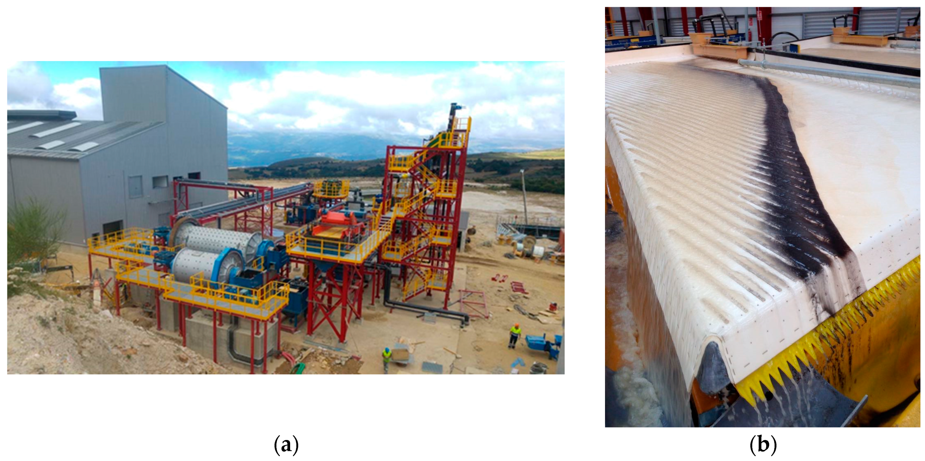
  • Gravimetric concentration. This involves several stages of gravity-assisted concentration made possible by density differences:
    • Spirals. Rougher, cleaner, recleaner and scavenger spirals remove the sterile material of lower density (gangue minerals such as silicates), concentrating the those of interest. The product then passes to the next stage.
    • Shaking tables. Rougher, cleaner, recleaner and scavenger stage shaking tables separate the minerals on the basis of their density. The product then passes to the next stage.
    • Falcon treatment. Gravimetric concentration, using centripetal force for the concentration of the finest metallic particles.
  • Low-intensity magnetic separation. This separates out the non-mineralogical iron (not associated with columbo-tantalite) as well as that released during milling. The aim is to improve the purity of the Sn to be obtained in later processing.
  • Drying. The gravimetric concentration process occurs under 30%/70% solid/liquid conditions. The resulting materials must, therefore, be dried before further processing.
Figure 1 provides a view of some parts of the plant where the Sn–Nb–Ta concentrate is obtained.
The distribution of the particle size was determined by diffraction using a Malvern Mastersizer S device (Malvern, Worcestershire, UK) equipped with a He–Ne laser (λ = 632.8 nm), employing dampened samples (dispersed in water containing an anti-flocculant in an ultrasonic bath). The concentrate produced was analyzed by X-ray fluorescence spectroscopy (XRF) using a Bruker S8 Tiger (Bruker, Billerica, MA, USA) device, and by atomic absorption (AA) using a SpectrAA 220 FS AA spectrometer (Varian, Palo Alto, CA, USA). The phase compositions were characterized by X-ray diffraction analysis (XRD) using a Siemens D5000 (Siemens, Berlin, German) apparatus and quantified by the Rietveld method. The concentrate was also subjected to morphological examination by field emission scanning electron microscopy (FE-SEM) using a JEOL JSM 6500 microscope (Jeol, Tokyo, Japan) equipped with an Oxford EDX energy-dispersive X-ray (EDX) analyzer for semi-quantifying the elemental composition (FE-SEM-EDX).
Metallic tin was obtained from the concentrate (held in graphite crucibles) via pyrometallurgical reduction smelting at 1100–1200 °C in an AFI-02 induction furnace containing an argon atmosphere. Different blends of graphite (Desulco® 9012S, 99.9% C, 0.041% S, 42 ppm N and 10 ppm H) and fluxes were tested (Table 1) as a means of reducing the melting point and to increase the Nb and Ta content of the slag produced. The furnace temperature was raised to 1200 °C. The Sn samples obtained were subjected to optical emission spectrometry (OES) using a Varian ICP-OES 725-ES (Varian, Palo Alto, CA, USA) instrument; all were attacked with lithium metaborate at 1050 °C and acidified with HNO3 before taking readings. The slag produced during the processing of the concentrate was characterized by electron microprobe microscopy (EMP) using a JEOL JEM 2100 microprobe (Jeol, Tokyo, Japan).
The metallic tin obtained by the pyrometallurgical reduction process was then melted and an ingot prepared (dimensions 18 cm × 10 cm × 0.6 cm, mass 0.688 kg) for use as an anode to allow its purification by electrorefining. Electrorefining was performed using a 5.3 L capacity electrolytic cell, into which two Sn cathodes (dimensions 15 cm × 11 cm × 0.1 cm, mass 200 g) and the prepared anode were inserted (order: cathode-anode-cathode) [21]. All electrodes were submerged in an electrolyte pumped continuously through the cell. The electrical current was supplied using a 32 V, 6A LNG 32-6 Heinzinger power supply. A Graphtec model GL220 MIDI Logger (Graphtec, Tokyo, Japan) was used to monitor the current. The cell voltage (Vc) was 0.5 V (calculated as the mean tension between the anode and cathode of the generator over time (t (h) of operation, at a current I). The electrolyte was prepared by dissolving 250 g Sn granules in 1 L of 18 M H2SO4 for 72 h with agitation. The resulting solution was filtered to remove any unwanted, presumably hydrated oxide-type precipitate. An aliquot of the filtrate was diluted with distilled water to obtain a concentration equivalent to 0.85 M H2SO4, containing 215 ± 6 mg/L Sn. This value was confirmed using a Perkin Elmer OPTIMA 3300 DV (Perkin, Waltham, MA, USA) optical emission spectrometer (OES) with an inductively coupled plasma (ICP) excitation source. Analytical grade thiourea (1 g/L) (Sigma-Aldrich, St. Louis, MO, USA) was added to the electrolyte to inhibit dendritic Sn crystal growth at the cathode. Table 2 summarizes the electrorefining conditions used.
The purified Sn deposits produced in the different tests were characterized by washing with distilled water, drying at 80 °C in an oven, and then melting at 1150 °C in a graphite crucible in an inert atmosphere inside a Morgan-type oven. The melted mass was poured into a mold to produce metallic bars of dimensions 60 mm × 26 mm × 10 mm for analysis. The chemical composition of these bars was determined using a Spectromax spark optical emission spectrometer (Spectromax, Surrey, UK). After each electrorefining process, the sludge deposited on the anode was washed with distilled water, dried at 80 °C, and weighed. Its chemical composition was then determined using a Varian SpectrAA 220 FS atomic absorption spectrometer (Varian, Palo Alto, CA, USA) equipped with a hydride generator. Figure 2 shows a diagram of the entire process followed.

3. Results

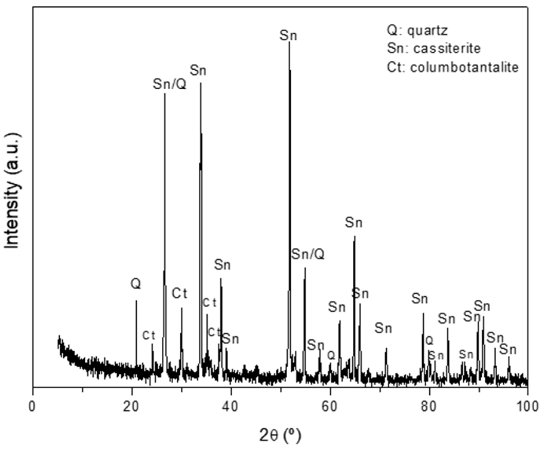
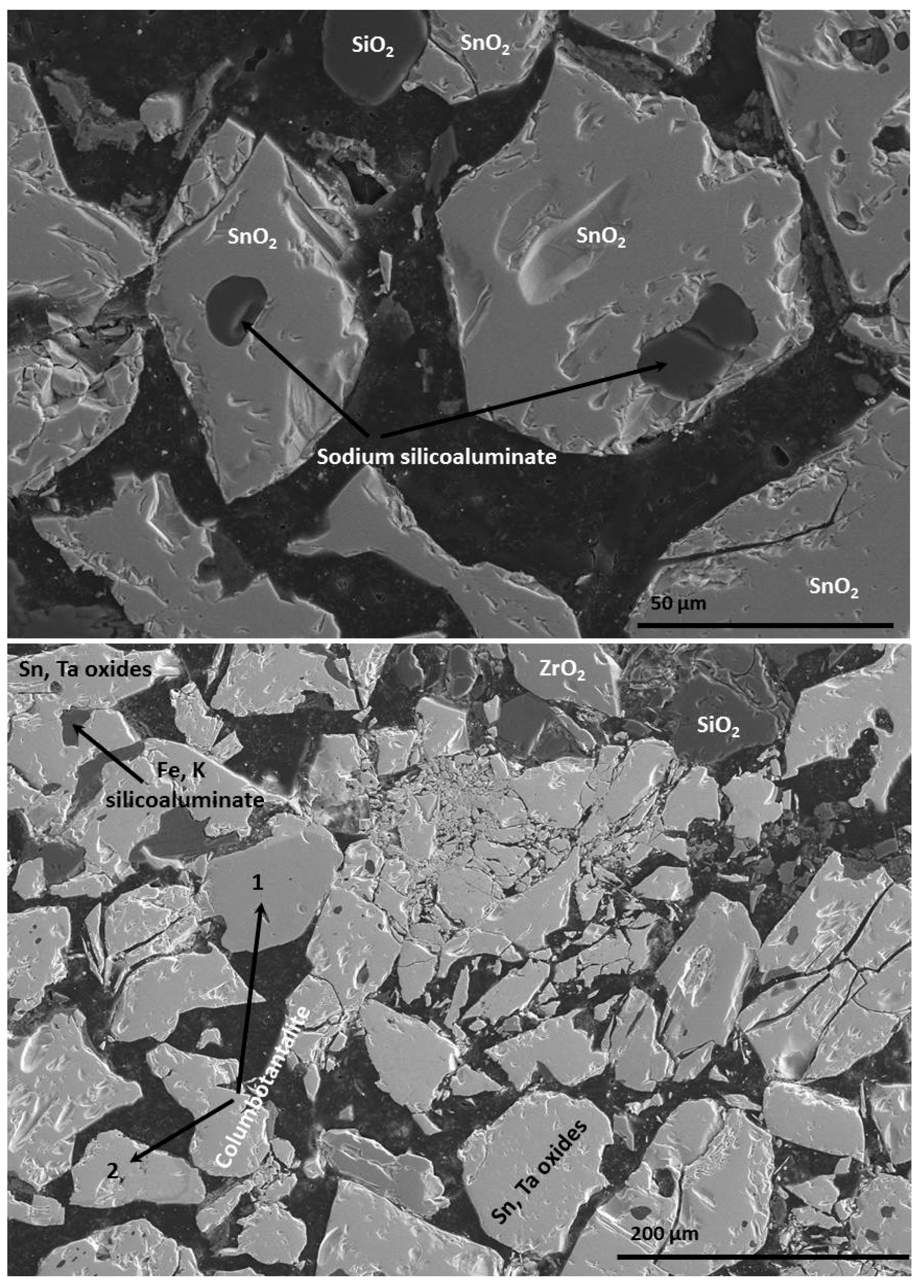
3.1. Chemical and Mineralogical Characterization of the Concentrate

The concentrate was composed of SnO2 (67.20 wt %), Ta2O5 (8.45 wt %), Fe2O3 (6.99 wt %) and Nb2O5 (5.40 wt %). The Rietveld-quantified majority phase was cassiterite (SnO2) (64.4%), followed by columbotantalite ((Fe,Mn)(Ta,Nb)2O6) (21.5%), and different phases containing Nb and Ta, such as ixiolite ((Sn,Fe)(Sn,Ta,Nb)2O6), and finally quartz (SiO2) (Figure 3). Figure 4 shows the mineralogical characteristics of the concentrate as determined by FE-SEM-EDX (Field Emission-Scanning Electron Microscopy-Energy Dispersive X-Ray). Large grains of cassiterite (SnO2) were seen, along with mixed grains of cassiterite-silico aluminates, Sn–Ta oxides, columbotantalite, quartz and zirconium oxide. The particle size distribution was: D10 = 0.61 µm; D50 = 9.85 µm and D90 = 10.44 µm.

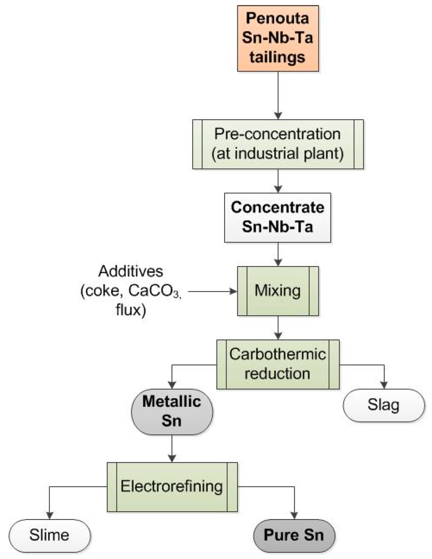
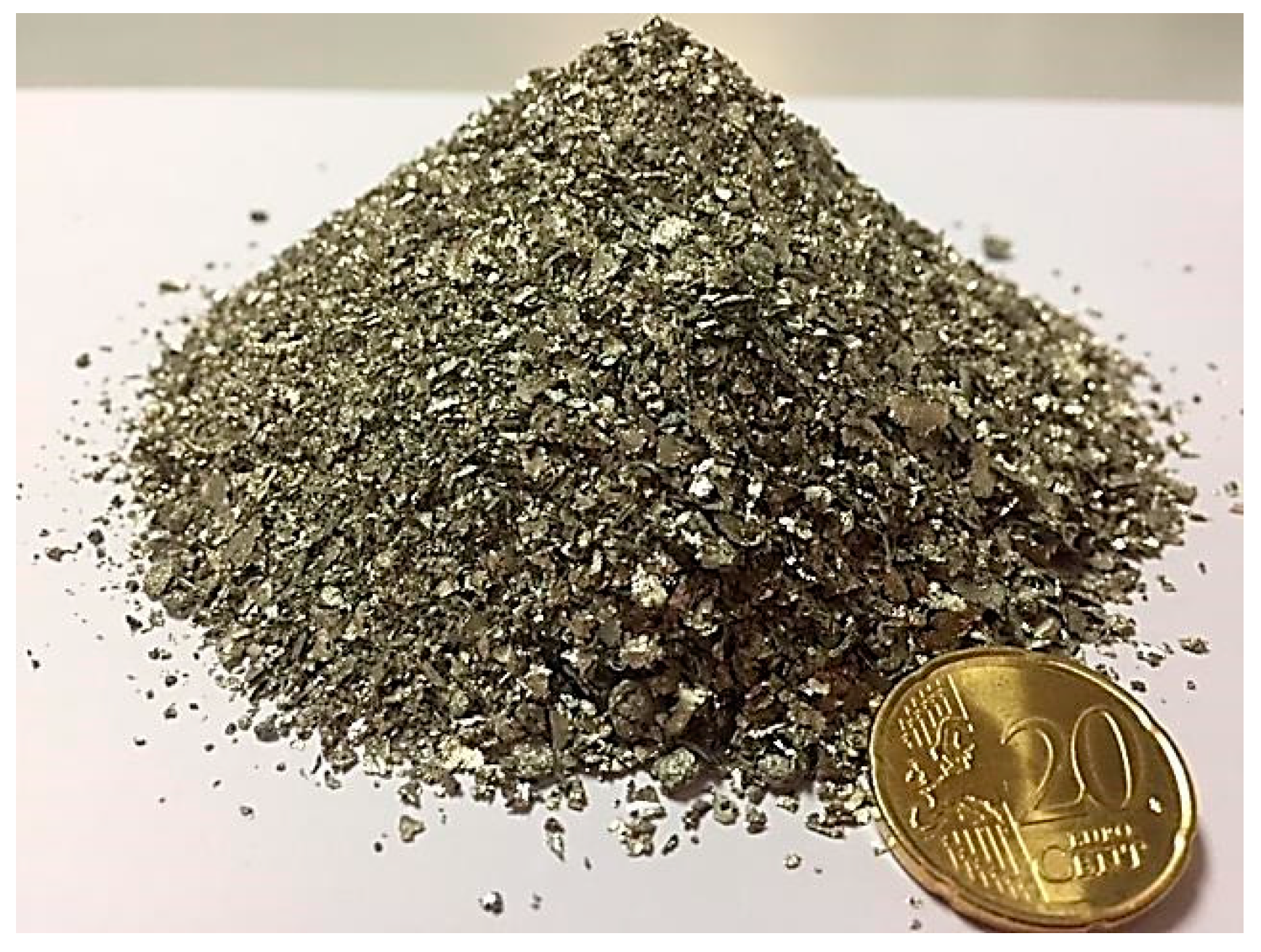
3.2. Obtaining Sn from the Mineral Concentrate

The greatest recovery of Sn (>95%) was obtained when using CaCO3 (blend A; Table 3). The OES analysis returned a percentage purity of 96% (Table 4), similar to that obtained with ores and other industrial wastes. However, the recovered metallic Sn had an Fe content of >3%; any Sn recovered by this method, therefore, requires purification. The presence of Fe is the consequence of its intrinsic presence in Penouta cassiterite. Given the relationship between the ionic radius and electronegativity, the isomorphic substitution between Sn2+/Fe2+ and Sn4+/Fe3+ occurs easily [22].

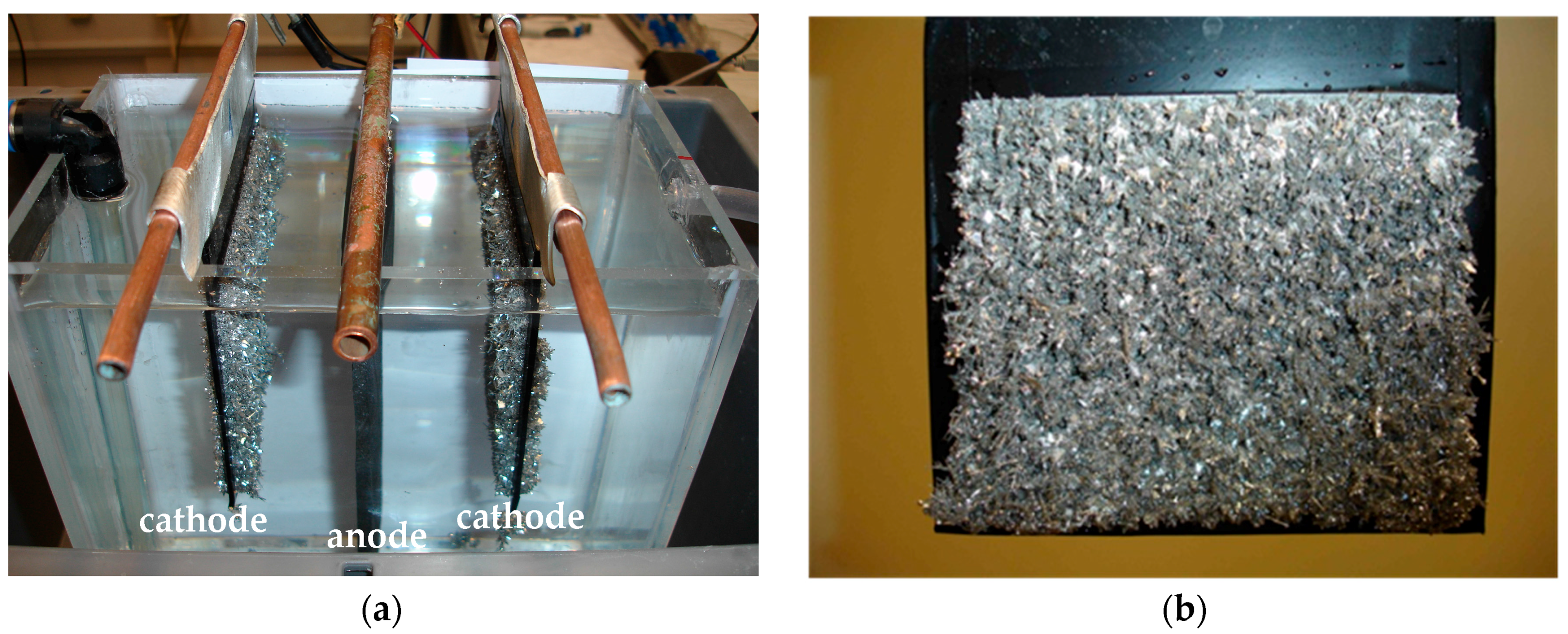
3.3. Electrorefining

Figure 5a shows the electrorefining cell and the cathodes with their Sn deposits. Figure 5b shows one of these cathodes on which the Sn deposit has taken the form of aciculate crystals. The quantity of Sn deposited was 2.5 g/h; the quantity of slime formed at the anode was 28 g/kg Sn. After 148 h of reaction, the Sn deposit had the chemical composition shown in Table 5; the same table shows the composition of the slime. The Sn obtained was very pure (99.97%); virtually all the Fe had been eliminated. The yield of purified Sn was 90% with respect to the Sn anode produced via carbothermic reduction. Figure 6 shows the highly pure Sn finally obtained.

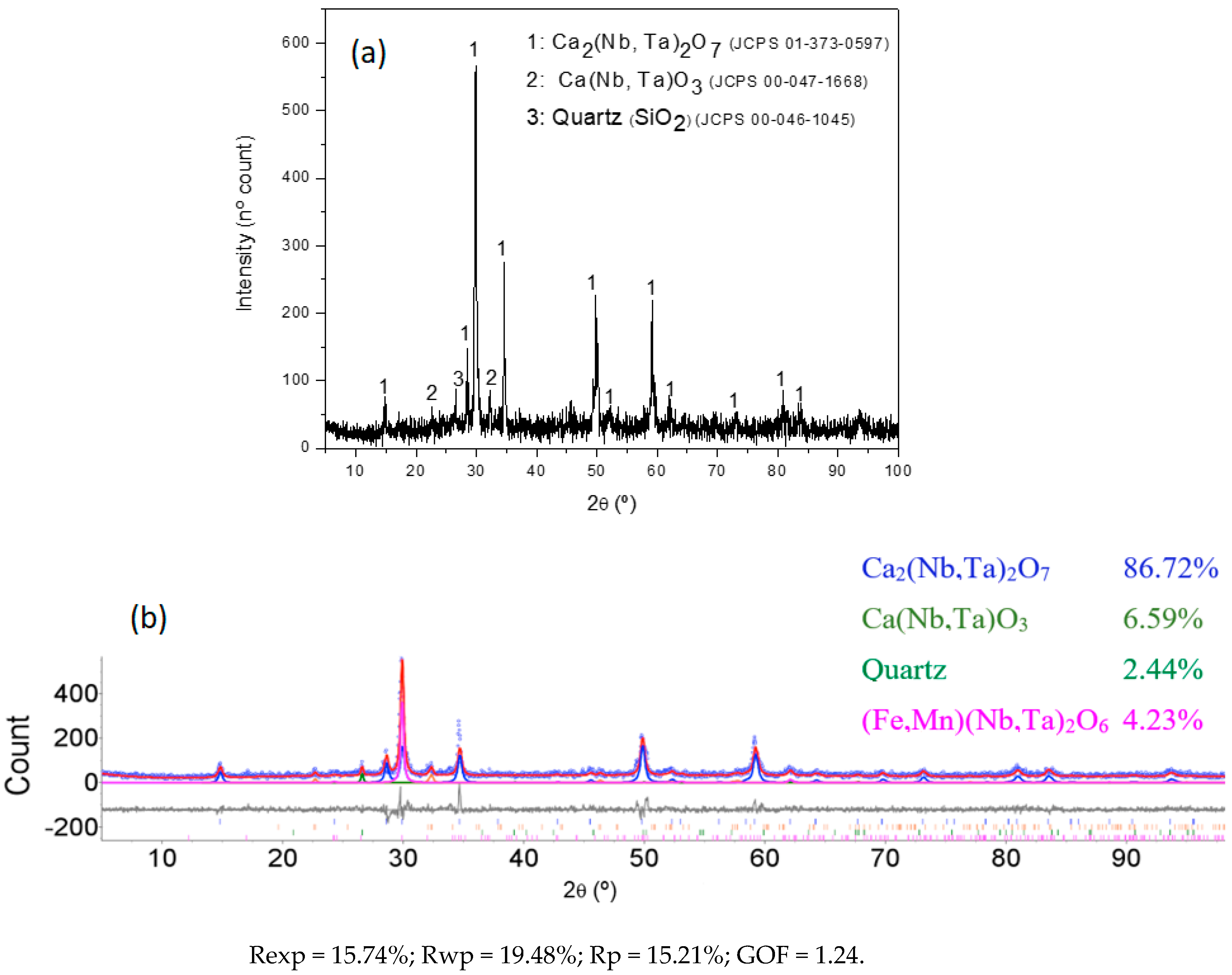
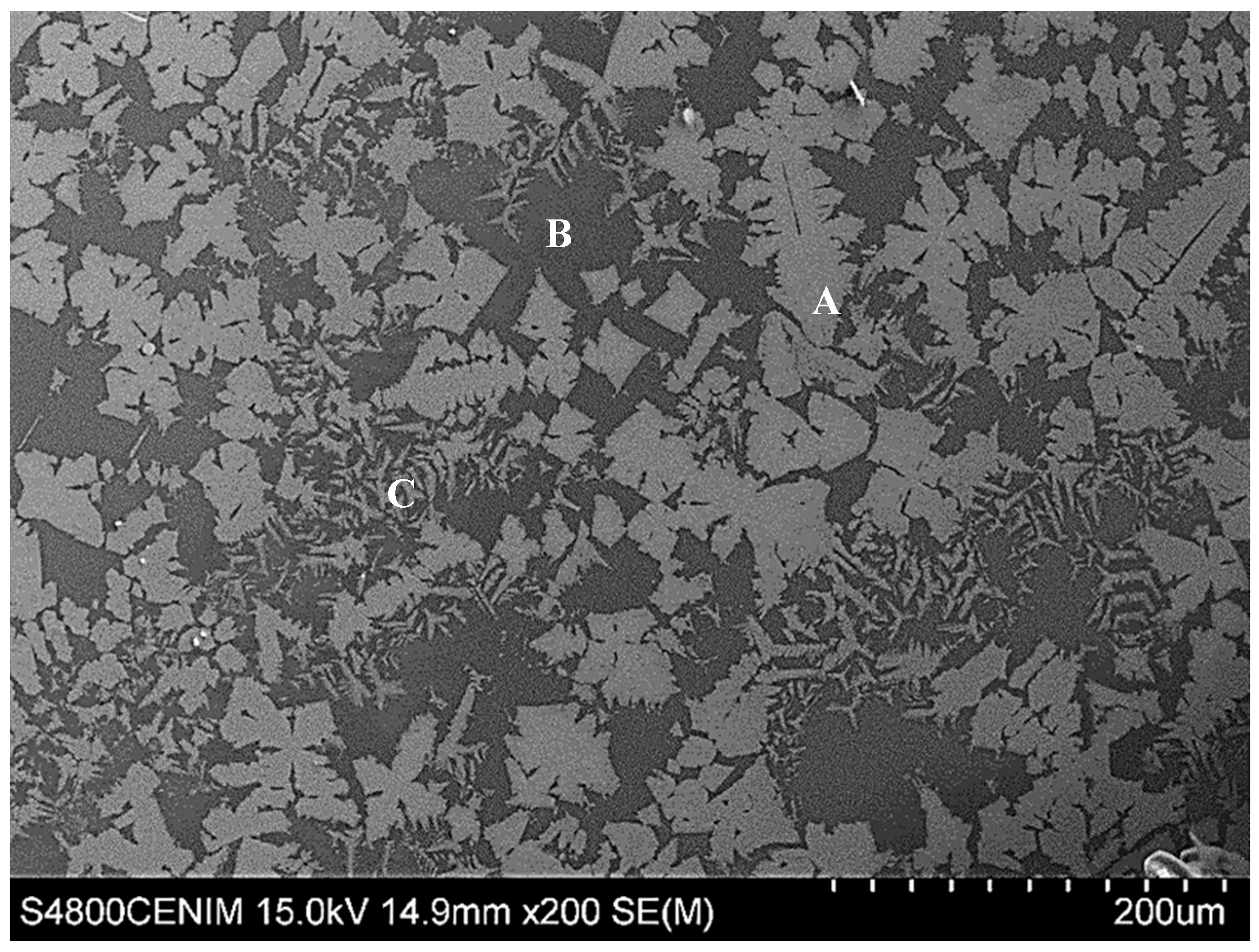
3.4. Characterization of the Slag Produced by the Pyrometallurgical Reduction Smelting Process

The mass of the slag obtained during the recovery of the Sn was equivalent to 25% of the mass of the initial concentrate. This easily ground, glassy material was characterized by XRF (Table 6). Its Nb2O5 and Ta2O5 contents reached 46% each. Mineralogically it contained Ca–Nb–Ta oxides of different stoichiometry (Ca2(Nb,Ta)2O7 and Ca(Nb,Ta)O3), plus much smaller proportions of other oxides of Nb, Ta, Mn and Fe ((Fe,Mn)2(Nb,Ta)2O6). Figure 7 shows the proportions recorded by the Rietveld method.
The slag was also characterized by EMP (Figure 8), which underscored the presence of mixed oxides of Nb–Ta–Ca, confirming the results obtained by XRD. Since oxides of Nb and Ta also concentrated in the slag, these metals might also be recovered, investing the tailings of the Penouta mine with further added value.

4. Discussion

Carbon dioxide can be combined with carbon and transformed into carbon monoxide by the reverse-Boudouard reaction [23]. This transformation is thermodynamically favored, beginning at 700 °C. As it is shown in Figure 9, the thermodynamic conditions would allow the reduction of SnO2 by carbon in standard states (applying unit value relative partial pressure of CO2) above approximately 700 °C. The required reaction would, however, more likely occur through an indirect mechanism, with CO acting as the effective reducing reagent. This would be kinetically and thermodynamically more feasible and beneficial. If the CO/CO2 mixture were correctly manipulated, the process would be possible at temperatures above 400 °C. The reducing CO would be produced by the initial oxidation of the graphite particles and the subsequent Boudouard reaction. However, the latter step requires temperatures higher than 800 °C (as is commonly known). The kinetics of the reduction reaction, however, might require even higher temperatures. Mitchell and Parker [24] reduced pure stannic oxide with anthracite and graphite powder, showing the reaction to be possible in the temperature range of 700–1200 °C, with the reaction rate strongly temperature-dependent. The rate of recovery is always proportional to the amount of carbon present, and the final carbon consumption corresponds to the overall reaction expressed as:
SnO 2 ( s ) +   C ( s )     Sn ( l ) +   CO 2 ( g )
The main steps of the reaction can be assumed as:
C ( s ) +   O 2 ( g )     CO 2 ( g )
C ( s ) +   CO 2 ( g )   2 CO ( g )
SnO 2 ( s ) + CO ( g )   SnO ( s , g ) + CO 2 ( g )
SnO ( s , g ) +   CO ( g ) Sn ( l ) + CO 2 ( g )
Additionally, the thermal decomposition of CaCO3 occurs at 800 °C according to Equation (6):
CaCO 3 ( s ) CaO ( s ) +   CO 2 ( g )
CaO accelerates the reduction of cassiterite by graphite and reduces the activation energy for the reduction reaction given its catalytic effect on the Boudouard reaction [25].
In the industrial plant where the tailings were treated, minimizing the Fe content of the cassiterite is a key objective. The concentrate used in the present work had a low Fe content (4.9%, or 7% when expressed as Fe2O3). It should be noticed that Fe oxides have a significant effect on the reduction of the Sn oxides during the reduction process [26]. The equilibrium diagram for the gas phase of these Fe and Sn oxides under different CO-CO2 atmospheres [27,28,29] indicates that the reduction of the Fe oxides is inevitable, and therefore that the Fe content of the raw material is <15%; were it any higher, it would affect the reduction of SnO2. In addition, any tin metal could easily combine with metallic Fe to form an alloy, and thus cause the loss of the Sn. Thus, the optimum conditions for melting the raw materials lie in the 700–1127 °C region, with a CO/(CO + CO2) ratio of 7–17% [29] in which tin oxides are reduced to tin metal but the iron oxides are reduced only to FeO. This latter FeO can then combine with the CaO and quartz in the concentrate to form Fe–Ca–Si compounds in the slag.
The use of CaCO3 in the pyrometallurgical reduction smelting process is essential for the formation of the slag. The CaO formed in the decomposition of the carbonate reacts with the columbotantalite and ixiolite to form mixed oxides of Ca, Nb and Ta—the majority compounds in the slag (Equation (7)), plus acicular Ca(Fe,Mn)2O2 (Figure 7). However, these latter ferrites were not detected by XRD, suggesting they may actually have an amorphous nature [30].
( Fe , Mn ) 2 ( Ta , Nb ) 2 O 6 ( s ) + 3 CaO ( s )   Ca 2 ( Nb , Ta ) 2 O 7 ( s ) + Ca ( Fe , Mn ) 2 O 2 ( s )
The enthalpy of formation (ΔHox) of Ca2Nb2O7, calculated from the binary oxides, is −208 kJ·mol−1 [30]. Thus, when the enthalpy of decomposition (ΔH) of CaCO3 is taken into account at 298 K (178.8 kJ·mol−1), the formation of the Ca2Nb2O7 becomes possible under the carbothermic reduction conditions employed. The literature contains no information on the formation of Ca2(Nb,Ta)2O7, but it is likely to be similar to that of Ca2Nb2O7 given the similarities of the CaO-Nb2O5 and CaO-Ta2O5 binary systems [31]. Finally, the formation of Ca(Fe,Mn)2O2 at temperatures around 1200 °C is a well-studied phenomenon of the sintering of iron minerals, and its appearance as acicular particles has been described by Cores et al. [32].
Our group is currently designing synthesis routes for obtaining Nb and Ta oxides. The classical route would involve dissolving the slag in HF/H2SO4, extraction with organic solvents, and re-extraction with ammonium salts (NH4F plus NH3). This would allow recovery of salts of the K2Ta2O3F6 and Nb2O5·nH2O type, from which the desired Nb and Ta oxides could be obtained [33].
Tin is normally deposited from divalent stannous ions, Sn2+, in an acidic (H2SO4) bath [34]. At the raw, non-refined tin anode, the following oxidation reaction occurs (8):
Sn → Sn2+ + 2e
At the highly pure tin cathode, the following reduction reaction occurs:
Sn2+ + 2e → Sn
The tin cathode builds up a coating of high purity tin, extracted from the anode. Impurities of higher electrode potential than tin (Fe, Bi, Sb, As, Cu, Ag, Au) mostly fail to dissolve from the anode, and build up a fine slime at its surface in their elemental or oxide form [18]. Due to uneven dissolution the anode slime also contains a significant amount of tin powder (see Table 5). This is suitable for further processing.
The theoretical quantity of metal deposited at the cathode obeys Faraday’s Law, expressed as follows:
m t =   A · I · t n   · F
where mexp is the mass of the metal (in grams) deposited at the cathode, A is the atomic mass of the metal, I the current used (expressed in Amperes), t the time elapsed (in seconds), n the number of electrons involved in the reaction, and F the Faraday constant. The resulting value for mt is 393.3 g.
The efficiency of the current (ŋ, %) was determined via Equation (11), comparing the mass of tin deposited at the cathode during electrolysis (mexp) and the mass of tin expected (mt) according to Faraday’s Law (Equation (10)).
η ( % ) = m e x p m t × 100
Under the reigning conditions the efficiency of the current was 93.9%
The specific energy consumption (CE, kWh/kg) was determined using Equation (12):
C E = V c · I · t 1000 · m e x p
in which Vc is the cell voltage (calculated as described above). Under the described conditions, and with a Vc of 0.5 V, the CE was 0.24 kWh/kg
It should be noted that the process described here could be used at other sites with tin oxides. It could also be used in the recovery of tin from metallic wastes (secondary tin) and even post-consumption wastes. It should also be remembered that today, in a world in which demand for this metal is rising, only 30% of all the tin consumed is recycled [26].

5. Conclusions

The results show that the present mining waste is a good source of cassiterite from which Sn can be obtained. When this is recovered by carbothermic reduction, the best flux to use is CaCO3. The purity of the recovered Sn is some 96%. In addition, 90% of this Sn can be turned into ultra-pure (99.97%) Sn via electrorefining. The slag produced in the carbothermic reduction contains Ca–Nb–Ta oxides, adding extra value to the mine tailings. Further work is underway to see how these latter elements may best be recovered from this slag.

Acknowledgments

Irene García-Díaz thanks the Ministry of Economy and Competiveness for her Postdoctoral Junior Grant (REF. FPDI-2013-16391).

Author Contributions

F.A.L. and F.G.P. conceived and designed the experiments; I.G.-D., O.R.L. and T.L. performed the experiments; F.A.L., I.G.-D. and O.R.L. analyzed the data; O.R.L. contributed reagents/materials/analysis tools; F.A.L. wrote the paper.

Conflicts of Interest

The authors declare no conflict of interest.

References

  1. ITRI. 2016 Report on Global Tin Resources and Reserves. Available online: https://www.itri.co.uk/index.php?option=com_mtree&task=att_download&link_id=55516&cf_id=24 (accessed on 12 January 2018).
  2. Angadi, S.I.; Sreenivas, T.; Jeon, H.-S.; Baek, S.-H.; Mishra, B.K. A review of cassiterite beneficiation fundamentals and plant practices. Miner. Eng. 2015, 70, 178–200. [Google Scholar] [CrossRef]
  3. Leistner, T.; Embrechts, M.; Leißner, T.; Chehreh Chelgani, S.; Osbahr, I.; Möckel, R.; Peuker, U.A.; Rudolph, M. A study of the reprocessing of fine and ultrafine cassiterite from gravity tailing residues by using various flotation techniques. Miner. Eng. 2016, 96–97, 94–98. [Google Scholar] [CrossRef]
  4. Feng, Q.; Zhao, W.; Wen, S.; Cao, Q. Activation mechanism of lead ions in cassiterite flotation with salicylhydroxamic acid as collector. Sep. Purif. Technol. 2017, 178, 193–199. [Google Scholar] [CrossRef]
  5. Sun, L.; Hu, Y.; Sun, W. Effect and mechanism of octanol in cassiterite flotation using benzohydroxamic acid as collector. Trans. Nonferrous Met. Soc. China (Engl. Ed.) 2016, 26, 3253–3257. [Google Scholar] [CrossRef]
  6. López-Moro, F.J.; García Polonio, F.; Llorens González, T.; Sanz Contreras, J.L.; Fernández Fernández, A.; Moro Benito, M.C. Ta and Sn concentration by muscovite fractionation and degassing in a lens-like granite body: The case study of the Penouta rare-metal albite granite (NW Spain). Ore Geol. Rev. 2017, 82, 10–30. [Google Scholar] [CrossRef]
  7. Johan, V.; Johan, Z. Accessory minerals of the Cínovec (Zinnwald) granite cupola, Czech Republic Part 1: Nb-, Ta- and Ti-bearing oxides. Mineral. Petrol. 1994, 51, 323–343. [Google Scholar] [CrossRef]
  8. Raimbault, L.; Cuney, M.; Azencott, C.; Duthou, J.-L.; Joron, J.L. Geochemical evidence for a multistage magmatic genesis of Ta-Sn-Li mineralization in the granite at Beauvoir, French Massif Central. Econ. Geol. 1995, 90, 548–576. [Google Scholar] [CrossRef]
  9. McLellan, B.; Yamasue, E.; Tezuka, T.; Corder, G.; Golev, A.; Giurco, D. Critical Minerals and Energy–Impacts and Limitations of Moving to Unconventional Resources. Resources 2016, 5, 19. [Google Scholar] [CrossRef]
  10. Llorens González, T.; García Polonio, F.; López Moro, F.J.; Fernández Fernández, A.; Sanz Contreras, J.L.; Moro Benito, M.C. Tin-tantalum-niobium mineralization in the Penouta deposit (NW Spain): Textural features and mineral chemistry to unravel the genesis and evolution of cassiterite and columbite group minerals in a peraluminous system. Ore Geol. Rev. 2017, 81, 79–95. [Google Scholar] [CrossRef]
  11. Peng, Z.; Mackey, P.J. New Developments in Pyrometallurgy. JOM 2013, 65, 1550–1551. [Google Scholar] [CrossRef]
  12. Zhang, Y.B.; Li, G.H.; Jiang, T.; Guo, Y.F.; Huang, Z.C. Reduction behavior of tin-bearing iron concentrate pellets using diverse coals as reducers. Int. J. Miner. Process. 2012, 110–111, 109–116. [Google Scholar] [CrossRef]
  13. Ha, H.; Yoo, M.; An, H.; Shin, K.; Han, T.; Sohn, Y.; Kim, S.; Lee, S.-R.; Han, J.H.; Kim, H.Y. Design of Reduction Process of SnO2 by CH4 for Efficient Sn Recovery. Sci. Rep. 2017, 7, 14427. [Google Scholar] [CrossRef] [PubMed]
  14. Komkov, V.G.; Gostishchev, V.V.; Ri, E.K. Physicochemical aspects of carbothermic reduction of cassiterite in the ionic melt. Russ. J. Non-Ferrous Met. 2009, 50, 596–599. [Google Scholar] [CrossRef]
  15. You, Z.; Li, G.; Wen, P.; Peng, Z.; Zhang, Y.; Jiang, T. Reduction of Sn-Bearing Iron Concentrate with Mixed H2/CO Gas for Preparation of Sn-Enriched Direct Reduced Iron. Metall. Mater. Trans. B 2017, 48, 1486–1493. [Google Scholar] [CrossRef]
  16. Van Deventer, J.S.J. The effect of admixtures on the reduction of cassiterite by graphite. Thermochim. Acta 1988, 124, 109–118. [Google Scholar] [CrossRef]
  17. Cetinkaya, S.; Eroglu, S. Thermodynamic analysis and reduction of tin oxide with methane. Int. J. Miner. Process. 2012, 110, 71–73. [Google Scholar] [CrossRef]
  18. Rimaszeki, G.; Kulcsar, T.; Kekesi, T. Application of HCl solutions for recovering the high purity metal from tin scrap by electrorefining. Hydrometallurgy 2012, 125–126, 55–63. [Google Scholar] [CrossRef]
  19. Rimaszeki, G.; Kulcsar, T.; Kekesi, T. Investigation and optimization of tin electrorefining in hydrochloric acid solutions. J. Appl. Electrochem. 2012, 42, 573–584. [Google Scholar] [CrossRef]
  20. Kekesi, T. Electrorefining in aqueous chloride media for recovering tin from waste materials. Acta Metall. Slovaca 2013, 19, 196–205. [Google Scholar] [CrossRef]
  21. López, F.A.; Alguacil, F. Recovery of high-purity Sn from Sn alloys containing Pb by means of electro refining. Patent WO 2016/075350-A1, 19 May 2016. [Google Scholar]
  22. Deposita, M. Magnetism in Cassiterite. Miner. Depos. 1966, 171, 148–171. [Google Scholar] [CrossRef]
  23. Nagase, K.; Shimodaira, T.; Itoh, M.; Zheng, Y. Kinetics and mechanisms of the reverse Boudouard reaction over metal carbonates in connection with the reactions of solid carbon with the metal carbonates. Phys. Chem. Chem. Phys. 1999, 1, 5659–5664. [Google Scholar] [CrossRef]
  24. Mitchell, A.R.; Parker, R.H. The reduction of SnO2 and Fe2O3 by solid carbon. Miner. Eng. 1988, 1, 53–66. [Google Scholar] [CrossRef]
  25. Padilla, R.; Sohn, H.Y. The reduction of stannic oxide with carbon. Metall. Trans. B 1979, 10, 109–115. [Google Scholar] [CrossRef]
  26. Su, Z.; Zhang, Y.; Liu, B.; Lu, M.; Li, G.; Jiang, T. Extraction and Separation of Tin from Tin-Bearing Secondary Resources: A Review. JOM 2017, 69, 2364–2372. [Google Scholar] [CrossRef]
  27. Zhang, Y.B. Research on Physicochemical Fundamental and New Technology of Tin, Zinc-Bearing Complex Iron Concentrate Pellets by Weak Reduction Roasting. Ph.D. Thesis, Central South University, Changsha, China, 2006. [Google Scholar]
  28. Su, Z.; Zhang, Y.; Chen, J.; Liu, B.; Li, G.; Jiang, T. Selective separation and recovery of iron and tin from high calcium type tin- and iron-bearing tailings using magnetizing roasting followed by magnetic separation. Sep. Sci. Technol. 2016, 51, 1900–1912. [Google Scholar] [CrossRef]
  29. Li, G.; You, Z.; Zhang, Y.; Rao, M.; Wen, P.; Guo, Y.; Jiang, T. Synchronous Volatilization of Sn, Zn, and As, and Preparation of Direct Reduction Iron (DRI) from a Complex Iron Concentrate via CO Reduction. JOM 2014, 66, 1701–1710. [Google Scholar] [CrossRef]
  30. Leitner, J.; Nevřiva, M.; Sedmidubský, D.; Voňka, P. Enthalpy of formation of selected mixed oxides in a CaO–SrO–Bi2O3–Nb2O5 system. J. Alloys Compd. 2011, 509, 4940–4943. [Google Scholar] [CrossRef]
  31. Ibrahim, M.; Bright, N.F.H.; Rowland, J.F. The Binary System CaO-Nb2O5. J. Am. Ceram. Soc. 1962, 45, 329–334. [Google Scholar] [CrossRef]
  32. Cores, A.; Mochón, J.; Ruiz-Bustinza, I.; Parra, R. Control of the flame front advance in a sintering bed of iron ores. Rev. Metal. 2010, 46, 249–259. [Google Scholar] [CrossRef] [Green Version]
  33. Nete, M.; Purcell, W.; Nel, J.T. Hydrometallurgical Separation of Niobium and Tantalum: A Fundamental Approach. JOM 2016, 68, 556–566. [Google Scholar] [CrossRef]
  34. Walsh, F.C.; Low, C.T.J. A review of developments in the electrodeposition of tin. Surf. Coat. Technol. 2016, 288, 79–94. [Google Scholar] [CrossRef]
Figure 1. Milling facility (a) and shaking table (b) for concentrating the Sn–Nb–Ta mineral.
Minerals 08 00020 g001
Figure 2. Process followed from tailings to recovery of pure Sn.
Minerals 08 00020 g002
Figure 3. X-ray diffraction analysis (XRD) patterns of the mineral concentrate.
Minerals 08 00020 g003
Figure 4. FE-SEM-EDX EDX (Field Emission-Scanning Electron Microscopy-Energy Dispersive X-Ray) images of the mineral concentrate.
Minerals 08 00020 g004
Figure 5. Electrolytic cell (a) and cathode (Sn deposit) (b).
Minerals 08 00020 g005
Figure 6. Highly pure Sn obtained by electrorefining.
Minerals 08 00020 g006
Figure 7. XRD pattern (a) and Rietveld fit for the X-ray diffractogram of the slag (b).
Minerals 08 00020 g007
Figure 8. SEM (Scanning Electronic Microscopy) image of the slag (A) 40.7% Ta2O5; 20.3% Nb2O5; 16.7% CaO; (B) 4.5% Ta2O5; 21.5% Nb2O5; 20.5% CaO; 12.5% MnO; (C) Ca(Fe,Mn)2O2.
Minerals 08 00020 g008
Figure 9. Ellingham diagram for tin oxide reduction.
Minerals 08 00020 g009
Table 1. Blends used in the pyrometallurgical reduction smelting process.
% (Weight)Blend ABlend BBlend C
Concentrate85.580.074.6
CaCO38.6-7.5
Borax-5.5-
Na2CO3-6.57.5
K2CO3--5.2
Graphite6.08.05.2
C/SnO2 (mol ratio)1/0.761/0.541/1.16
Table 2. Electrorefining conditions.
Current (A)Electrolyte Flow Rate (L/h)Anode-Cathode Separation (cm)Reaction Time (h)
1.20
(190.1 A/m2)
54148
Table 3. Tin recovery via the pyrometallurgical reduction smelting process depending on the type of mixture used.
BlendSn Recovery (wt %)
Blend A95.2 ± 3.8
Blend B87.6 ± 0.6
Blend C54.0 ± 0.3
Table 4. Chemical composition of tin metal obtained by the pyrometallurgical reduction smelting process.
ElementContent
Sn96.06 wt %
Fe3.46 wt %
Mn0.19 wt %
Nb998 ppm
Cr899 ppm
Ti385 ppm
Cu276 ppm
Table 5. Chemical composition (mass %) of the Sn deposited, and of the slime.
MetalSnFeAgCuPb
Pure Sn99.970.0050.0070.0100.009
Anode Slime53.280.440.1644.491.63
Table 6. Chemical composition of the slag (expressed at wt % of oxides).
ComponentContent (wt %)
Ta2O525.48
Nb2O521.43
CaO15.79
SiO210.00
MnO7.23
SnO25.66
ZrO23.68
Al2O33.23
Fe2O30.73
TiO20.62
K2O0.51
Na2O0.30
MgO0.14

