Article

The Effect of Ore Pre-Heating on the Operation of a 300 kVA Submerged Arc Furnace for High Carbon Ferromanganese Alloy Production—Pilot Study Results

Mintek, Private Bag X 3015, Randburg 2125, Gauteng, South Africa
*
Author to whom correspondence should be addressed.
Minerals 2025, 15(9), 968; https://doi.org/10.3390/min15090968
Submission received: 19 May 2025 / Revised: 27 August 2025 / Accepted: 5 September 2025 / Published: 13 September 2025
(This article belongs to the Section Mineral Processing and Extractive Metallurgy)

Abstract

The effect of ore pre-heating on the operation of a 300 kVA Submerged Arc Furnace (SAF) for high carbon ferromanganese (HCFeMn) alloy was investigated. The two types of Mn ores from the Kalahari Manganese Field (KMF) were used in the investigation (Ore #1 and Ore #2). Quartz and coke sourced from South Africa were used as a fluxing agent and a reductant, respectively. The Mn ores, reductant and fluxing agent were delivered to Mintek with a size range of +6–20 mm and were sent to our in-house laboratories to determine the chemical and physical properties. The samples were taken for Inductively Coupled Plasma Optical Emission Spectroscopy (ICP-OES), combustion method (LECO), proximate analysis and quantitative X-ray diffraction (QXRD). A newly designed and constructed pilot facility at Mintek was used in the investigation. The facility included a 1 t/h rotary kiln coupled to an electric arc furnace supplied with an alternating current (AC) with a 300 kVA tap-changer transformer. The main aim of the investigation was to demonstrate the effect of ore pre-heating to 600 °C on the furnace energy consumption and CO/CO2 emissions. The experimental approach adopted involved feeding Mn ore to establish baseline operating conditions, followed by feeding of Mn ore pre-heated with a rotary kiln to compare operational parameters. The pilot campaign experienced several operational challenges but there were periods of stable operation that enabled data collection for furnace energy consumption and CO/CO2 emissions. The effect of pre-heating the ore to 600 °C on the SAF energy consumption and CO/CO2 emissions was demonstrated successfully and revealed that energy savings and reduction in furnace CO2 emissions is achievable. Pre-heating Mn ore to 600 °C lowered the furnace energy consumption by an average of 22.5% and CO2 emissions by an average of 37%. The campaign also achieved an overall manganese recovery of 86%. Operating the furnace with hot feed increased the heat losses through the roof by 300% compared to heat losses observed during cold feed. There were also no significant changes in the furnace electrical parameters observed between the two feed modes.

1. Introduction

Manganese is a strategic metal with various industrial applications that are crucial to mankind, for example, alloying, battery electrons, medicinal needles, chemicals, etc. [1,2,3,4,5]. High Carbon Ferromanganese (HCFeMn) alloys are produced by smelting manganese ores in an electric furnace using a carbon-containing reductant; this generates CO2 emissions which contribute to climate change [6]. This traditional way of producing HCFeMn alloys is highly energy intensive [1,7,8,9]. Energy demand has been increasing exponentially over the past two decades due to increasing population and industrialization [10]. Most of the energy utilized in the world is produced from fossil fuels, which release large quantities of CO2 [10]. As a result, there is a global effort to reduce the energy consumption of industrial processes and greenhouse gas (GHG) emissions from industrial processes [8,11].
PREMA is a Horizon 2020 project, funded by the European Union, aimed at demonstrating an innovative suite of technologies, involving the use of industrial off-gases and solar thermal energy [7]. This was mainly performed to reduce energy consumption and CO2 emissions from manganese ferroalloy production. One of the suites of technologies targeted for demonstration by the PREMA project was the integration of a pre-heater in the process to produce HCFeMn alloy. This new pre-heating unit would use greener energies, such as biocarbon, solar energy, or even by-products considered as waste, such as CO-rich off-gases from the Submerged Arc Furnace [7]. The project explored several pre-heating technologies, namely rotary kilns, shaft kilns and packed bed heaters using various heat sources. The study by [12] explored the technical feasibility of using solar energy to pre-heat manganese ores in a sinter plant. The study revealed that using solar energy for pre-heating can provide significant cost savings compared to the use of fossil fuels. However, more detailed analysis is recommended to establish technical opportunities of integrating a concentrated solar thermal (CST) heating unit into an existing sinter plant. Pre-heating of manganese ores in a packed bed column using air was explored in the study [13]. The experiment was at a lab scale, but the temperature field data generated from the model can be used for sizing pre-heating units and implementation of control protocols for the process [13].
The paper by [14] outlined the individual steps in the process scale-up towards an industrial scale plant for the pre-treatment of manganese ores. The study explored the reactions that take place during the pre-treatment, which include moisture removal, decomposition of carbonated minerals and possible decomposition of manganese oxides. The study by [4] compared the technical advantages and capital costs of different pre-treatment technologies. Pre-treatment in the study included pre-heating, calcination and sintering of manganese ores. The technologies assessed were a rotary kiln, shaft kiln, steel belt kiln and travel grate kiln. The shaft and rotary kilns are applicable to granular manganese ores while the steel belt and travel grate kilns are appropriate for fine manganese ores due to sintering. The latter is very important as it promotes the use of fines, which is not often considered in the industrial processes. Pre-heating in a shaft and rotary kiln require granular ore as thermal disintegration of the ore is likely. The potential of disintegration to form fines positions the use of a shaft kiln at a disadvantage due to fines negatively affecting its smooth operation. The presence of fines in the shaft kiln results in the risk of clinkering that may cause blockages. There is no risk of blockages with the use of a rotary kiln, which results in a stable supply of raw material to the furnace. The stable supply of ore ensures that the composition of the burden in the Submerged Arc Furnace (SAF) is uniform, which positively affects the efficiency of the process. Integrating the rotary kiln into the process offered lower capex costs compared to the shaft kiln, and this supported the decision to use the rotary kiln.
The rotary kiln is widely used in the industry for multiple applications which include pre-heating, pre-reduction, calcining and roasting [15]. The pre-heating of manganese ores in a pilot-scale rotary kiln was studied by [6] at Eramet ideas in France. The reaction kinetics of decomposition and pre-reduction of manganese oxides are difficult to control in a SAF, and this leads to overconsumption of reductant and higher CO2 emissions [6]. The reduction reaction to produce Mn metal produces CO2 as a byproduct. The CO2 produced participates in the endothermic Boudouard reaction at temperatures more than 800 °C, which consumes energy and reductant. This elevates reductant energy consumption by the process [6]. The main aim of the study was to optimize ore heating and pre-reduction before the SAF in a separate unit to reduce its electricity consumption and CO2 emissions. The effect of an integrated pre-heater on the production of FeMn alloy was demonstrated during continuous pilot-scale experiments at Mintek’s facilities. Raw materials for the demonstration work were sourced from a local South African manganese ferroalloys producer. A new facility was designed and constructed for this demonstration. The facility was a 300 kVA Alternating Current (AC) SAF coupled to a 1 ton/hour electrically heated rotary kiln. The aims of the study were to (i) demonstrate the effect of the preheater operation on the SAF operation and (ii) determine the effect of pre-heating the ore to 600 °C on SAF energy consumption and CO2 emissions. There were other work packages that evaluated the use of various sources of renewable energy to be used to pre-heat the ore. This work package focused only on demonstration of the process at a pilot scale, which is the work that is discussed in this article.

2. Materials and Methods

2.1. Materials

The raw materials used in the demonstration were sourced from a South African manganese ferroalloys producer, who sourced the ores from the Kalahari Manganese Field (KMF). Two raw materials, namely coke (reductant) and quartz (flux) were sourced in addition to the two manganese ores. The raw materials were all delivered with a size fraction of +6–20 mm. The size fraction of +6–20 mm was recommended by the industrial partners of the project as it allowed proper burden permeability in the SAF. The pictures of the raw materials and the particle size distribution (PSD) are shown in Figure 1 and Figure 2, respectively.

2.2. Characterization

2.2.1. Chemical Composition

The chemical composition of the raw materials was determined by Mintek’s Analytical Chemistry Division. The two ores and reductant were sent for Inductively Coupled Plasma Optical Emission Spectroscopy (ICP-OES) to determine their chemical composition. With this technique, a sample mass of 0.2 g was weighed and mixed with 3 g of sodium peroxide (Na2O2), used as a flux. The mixture was fused in a fusion machine and then allowed to cool to room temperature. The solid fused sample was then completely digested in a beaker with 40 mL of HCl (1M) acid solution. The digestion liquor was transferred into a 200 mL volumetric flask containing 10 mL of an internal standard solution. The volumetric flask was then filled to the 200 mL mark with distilled water. The resultant solution in the volumetric flask was then analyzed by ICP-OES. The reductant was also sent for combustion method by LECO (developed by LECO Corporation in St Joseph, MI, USA) and proximate analysis to determine the total Carbon (C), Sulfur (S), volatile matter (VM) and ash component of the coke. With this technique, the samples were heated in an oxygen combustion furnace, and the S was oxidized and detected as SO2 by an infrared detector. Carbon was also oxidized and detected as CO2. The chemical composition of the raw materials is shown in Table 1.

2.2.2. Phase Chemical Composition

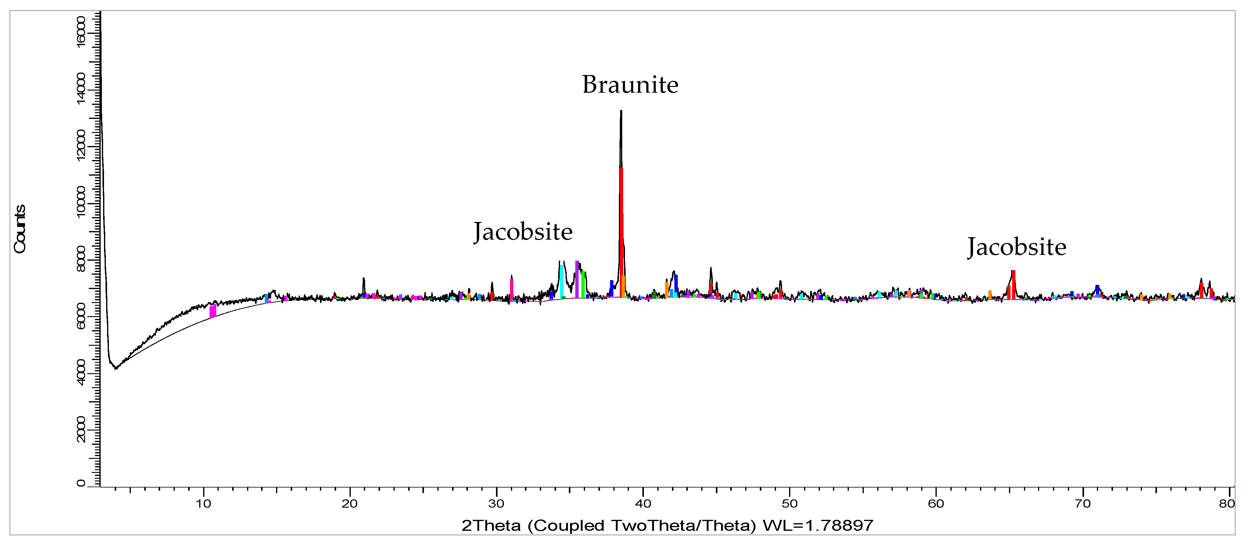
The phase chemical composition of the two ores was determined by Mintek’s Mineralogy Division by quantitative X-ray diffraction (QXRD). The samples were first pulverized then micronized to achieve a particle size below 20 µm to ensure the acquisition of more representative data for mineral and elemental quantification. The samples were subjected to the Bruker D8 diffractometer (supplied by Karlsruhe, Germany) equipped with Fe-filtered Co Kα radiation and run over a 2-theta range of 5–80 degrees with a step size of 0.02 degrees 2 theta. Minerals were initially identified using Bruker EVA® software, version 4.2.2, while the quantification of minerals was performed using TOPAS® software, version 4.2. The bulk phase chemical composition of the two ores is shown in Table 2. The XRD diffractograms for Ore #1 and Ore #2 are shown in Figure 3 and Figure 4, respectively.

2.3. Experimental Equipment

The detailed description of the equipment used (furnace lining, rotary kiln specifications, thermocouple locations, gas analysis connection and furnace dimensions) in the test work is described in the article by Moholwa et al. [16]. The facility is divided into five sections, namely, feed system, rotary kiln, furnace, micro-GC (gas chromatography) and off-gas treatment system. Figure 5 shows the general arrangement of the components.

2.4. Experimental Procedure

The start-up heel consisted of HCFeMn fines, coke and a mild steel former, which was cylindrical in shape with both ends open. HCFeMn fines (weighing 100 kg) were placed on the hearth up to the level of the tap hole. The cylinder (weighing 25 kg) made of 3 mm thick plate with a height and diameter of 500 mm and 700 mm, respectively, was placed on top of the fines. The inside of the cylinder was filled with 23 kg of coke and the outside was filled with 20 kg of ore mixture to prevent the cylinder from shifting during the heat-up. The cylinder (mild steel former) was positioned such that all three electrode tips were located inside the cylinder. Experience from earlier test work identified the need to add coke from time to time during furnace warm-up. As such, the cylinder helped to ensure that the coke added during the warm-up was directed towards the electrode tips where it is needed. The picture of the heel formation is shown in Figure 6.
The furnace and refractory heat-up was conducted over a period of 26 h, which included 2 h of power outage. The refractory heat-up rate was kept between 20 °C/h and 60 °C/h. This was to ensure that the refractory did not experience thermal shock during the heat-up process. Feeding commenced once the hearth and shell refractory temperatures were above 600 °C; this was performed slowly to establish stable feed operations and to build the burden. Non-preheated (cold feed) material was initially fed to establish the base operation parameters. Once the burden was built up and the furnace had reached stable operation, the data related to furnace operation was collected. The data included furnace energy requirement and the composition of the off gas. After seven days of cold feed, a transition to feeding pre-heated (hot feed) material was started, which took a day to complete. During hot feed, a burden was built up and the furnace was stabilized as it was performed during cold feed. The same data that was collected during cold feed was also collected during hot feed. The purpose was to compare the two data sets to see the effect of a preheater on the operation of the SAF.

3. Results and Discussion

3.1. Heat Losses Estimation

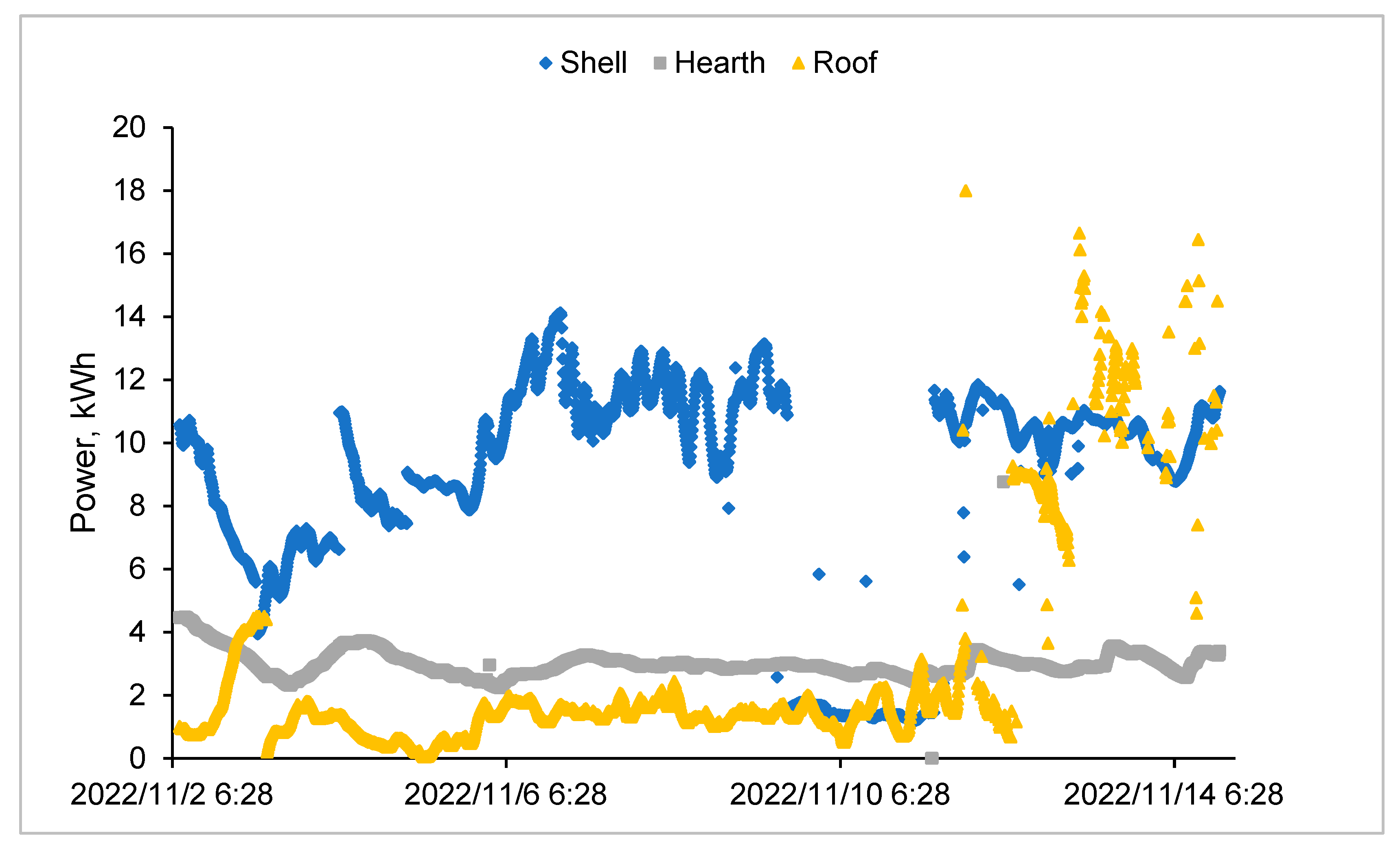
The readings from the thermocouples in the furnace body were used to estimate heat losses from the furnace. The layout of thermocouples was discussed in the article [16] published in 2023. Several thermocouples were located closer to the hot face and others much further from the hot face. The heat losses were calculated based on the temperature differences between the thermocouples. Equation (1) was used to calculate energy losses from the furnace. Figure 7 shows the heat losses from the shell, hearth and roof for the period of the demonstration. The heat losses through the roof of the furnace averaged at 2 kWh and 8 kWh during cold feed and hot feed, respectively. The increased heat loss through the roof was due to an increased temperature of the furnace burden during hot feed. During hot feed, the burden had two sources of heat: the energy from the reaction zone and the heat transferred to the ore in the kiln. No meaningful change in heat losses from the hearth and shell were seen when the test campaign moved from cold feed to hot feed. Pre-heating the ore raises the roof temperatures; intense cooling of the roof would be necessary on an industrial furnace to ensure longevity of the roof lining. Alternatively, a lining that can handle high operating temperature can be used for the roof.
Thermal conduction equation
E = kΔT
E—Energy/heat losses (kWh)
k—Refractory thermal conductivity (kWh/°C)
ΔT—Temperature difference between two thermocouples (°C)

3.2. Specific Energy Requirement (SER)

The specific energy requirement (SER) was estimated using the data logged by the DeltaV historian in 10 min intervals. The SER was calculated using mass fed data, furnace power input and heat losses calculated from temperature differences, see Equation (2). There were periodic power cuts during the demonstration; as a result, not all taps were considered when calculating the average energy requirement of the furnace. The average SER for cold feed was 1.9 kWh/kg of feed material (with a standard deviation of 0.1). The average tapping temperatures for tap 33 and 35 were 1178 °C and 1215 °C for metal and slag, respectively. The same equation that was used to calculate the SER during cold feed conditions was also used to calculate the SER during hot feed conditions. The average SER for hot feed was 1.5 kWh/kg of feed material (with a standard deviation 0.1). The average tapping temperatures for the selected taps were 1308 °C and 1316 °C for metal and slag, respectively. This is a drop of 22.5% in SER during the hot feed condition. The reduction in SER during hot feed is due to an increased burden temperature. The increased burden temperature meant that less energy from the furnace power supply would be needed to melt the material, leading to a reduced SER.
Specific energy requirement calculation
SER = ([Energy IN − Heat losses])/(Mass fed)
where
SER—Specific energy requirement of smelting process (kWh/kg of total feed)
Energy IN—Total electrical energy input from the furnace (kWh)
Heat losses—The average heat energy lost from the furnace through the refractory, shell, roof and hearth (kWh)
Mass fed—Total of all feed materials fed to the furnace during the tap
Boudouard reaction
C + CO2 = 2CO
Ore #1 and Ore #2 contain carbonated minerals (i.e., Calcite, Kutnohorite and Dolomite), as shown in Table 2. As indicated in studies [6,9,17], these decompose during the pre-heating process to release CO2 as one of the products. During cold feed, these decomposition reactions take place in the burden of the furnace, which is at temperatures above 800 °C. The CO2 participates in the endothermic Boudouard reaction at temperatures above 800 °C, as indicated by the study [6]. The Boudouard reaction shown in Equation (3) consumes energy, leading to increased furnace energy consumption. During hot feed, these reactions take place in the kiln, reducing CO2 to participate in the Boudouard reaction. The energy that would have been consumed by the Boudouard reaction is then utilized in the process, which reduces the overall energy consumption by the process. These are some of the reasons we observed a decreased consumption of energy during hot feed. The higher manganese oxides are reduced by either dissociation (reaction 4 to 6) or reaction with CO gas (reaction 7 to 9) [9]. CO2 produced from the reaction with CO gas will once again take part in the Boudouard reaction to release energy. The dissociation reactions are endothermic and take place in the furnace burden during cold feed. This also explains the higher furnace energy consumption during cold feed. There is no CO gas expected in the rotary kiln; therefore, reactions 7 to 9 are not expected in the rotary kiln. Due to operational challenges, it was difficult to control the tapping temperature of the products. The tapping temperatures were higher by 100–150 °C during hot feed when compared to cold feed. If the hot feed tapping temperatures could be lowered to match the cold feed temperatures more energy savings could be seen from the test work.
4MnO2 = 2Mn2O3 + O2
6Mn2O3 = 4Mn3O4 + O2
2Mn3O4 = 6MnO + O2
2MnO2 + CO = Mn2O3 + 2CO2
3Mn2O3 + CO = Mn3O4 + CO2
Mn3O4 + CO = 3MnO + CO2

3.3. CO/CO2 Emissions

A gas chromatograph described in the study [16] was used to determine the composition of the off-gas exiting the furnace. During the pilot campaign, the piping used to extract the off gas from the furnace became clogged with dust 2 to 3 h into the operation. The aim was to measure the gas composition continuously; however, due to the regular cleaning that was needed when the gas piping was clogged, this could not be accomplished. The measurements were therefore taken intermittently, and four measurements were completed for the cold feed and hot feed period of the campaign. The results are presented in Table 3. One of the campaign’s objectives was to compare the difference in CO and CO2 emissions during periods of hot and cold feed. From Table 3, it can be seen that the CO percentages increased from an average of 20.2% to 24.5% when hot feed was fed instead of cold feed. It can also be seen that CO2 has reduced from an average of 15.3% to 9.7% when moving from cold feed to hot feed. From the phase chemical composition of the ores shown in Table 2, the two ores contain carbonated minerals. The carbonated minerals contained in the ore are Kutnohorite, Calcite and Dolomite. These carbonated minerals decompose during the pre-heating process and produce CO2 as one of the products, as mentioned in Section 3.2. During cold feed, the decomposition of carbonated minerals takes place in the burden, which leads to increased CO2 in the furnace off-gas. The decomposition of carbonated minerals takes place in the kiln during hot feed, which leads to decreased CO2 in the furnace off-gas. This is the main reason the CO2 concentration drops. This drop means that there is less CO2 to participate in the Boudouard reaction to form CO. The reduced occurrence of the Boudouard reaction results in reduced reductant consumption, as indicated by the study [6]. This is evident in the overall mass balance that showed that the average coke consumption during cold and hot feed was 54 kg and 43 kg per batch, respectively. The reduced reductant consumption leads to reduced CO2 emissions.

3.4. Overall Mass Balance

The overall mass balance is presented in Table 4. The mass balance only includes masses of solid feed and product material that could be collected and weighed during the campaign. The campaign had a total of 35 taps; the furnace processed a total of 10,424 kg feed and produced 6330 kg of products. The metal accounted for 28% by mass of the products, slag 65% and dust 7%. The campaign had an overall mass loss of 37% that can be attributed to the process gases emanating from the decomposition of carbonates in the Mn ore, oxidation of C to CO and CO2 gas during reduction of the metal oxides and the release of volatile constituents from the raw materials.

3.5. Elemental Mass Balance

The recovery and distribution of major elements from the campaigns are presented in Table 5. The exceptionally low recovery of C results from the escape of C from the system in the gaseous phase (CO or CO2). Mn, Si and Ca had good recoveries as they mainly report to the slag. Mg is present in low concentrations in the feed materials and elements, with low concentrations tending to have low recoveries at pilot plant scale. This happens due to small variations in the assays of the products having a large impact on the recovery. The campaign was able to achieve an overall Mn and Fe recovery of 48% and 86% to the metal, respectively. The majority of Mn and Fe were distributed to the metal while the majority of Ca was distributed to slag.
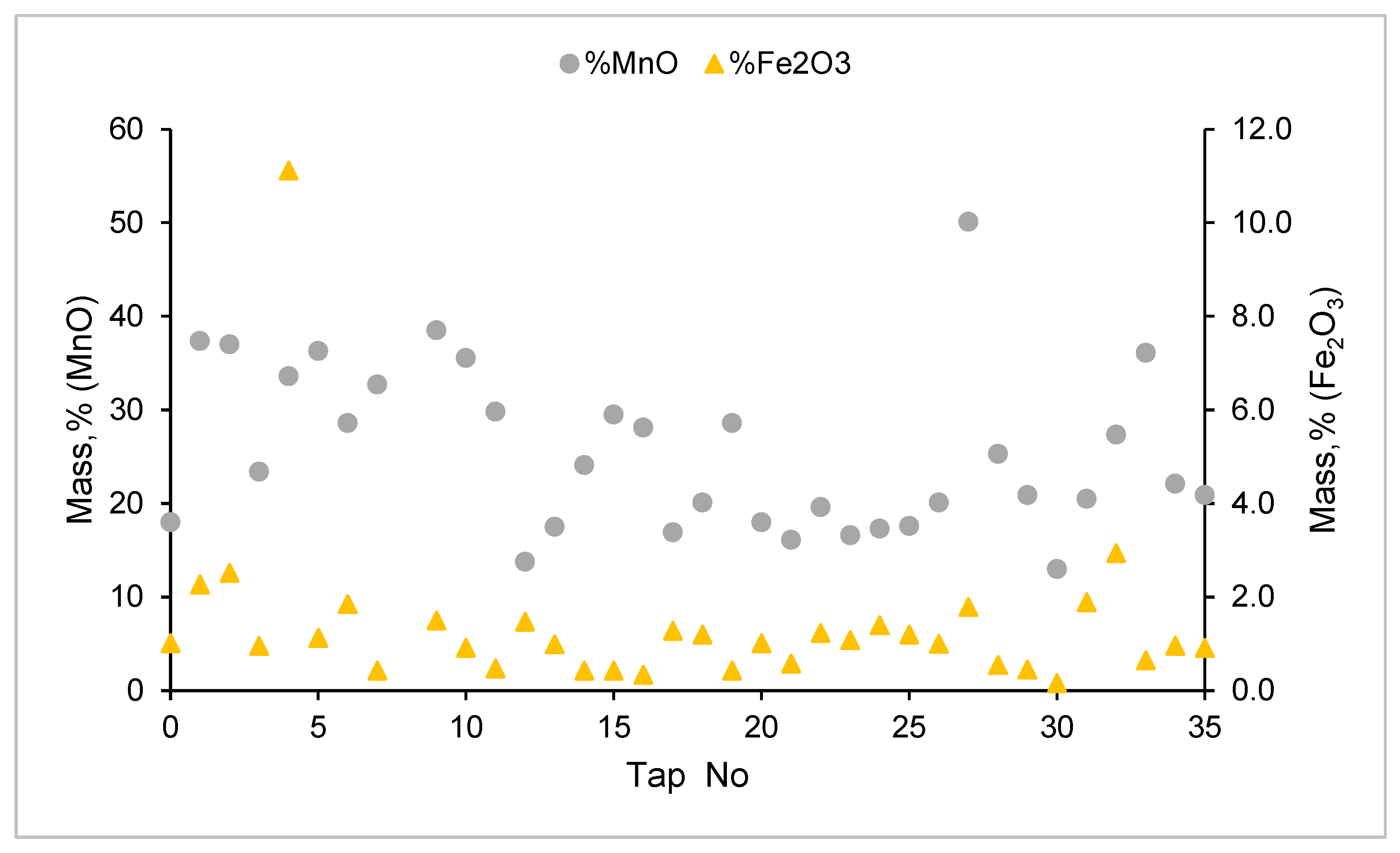
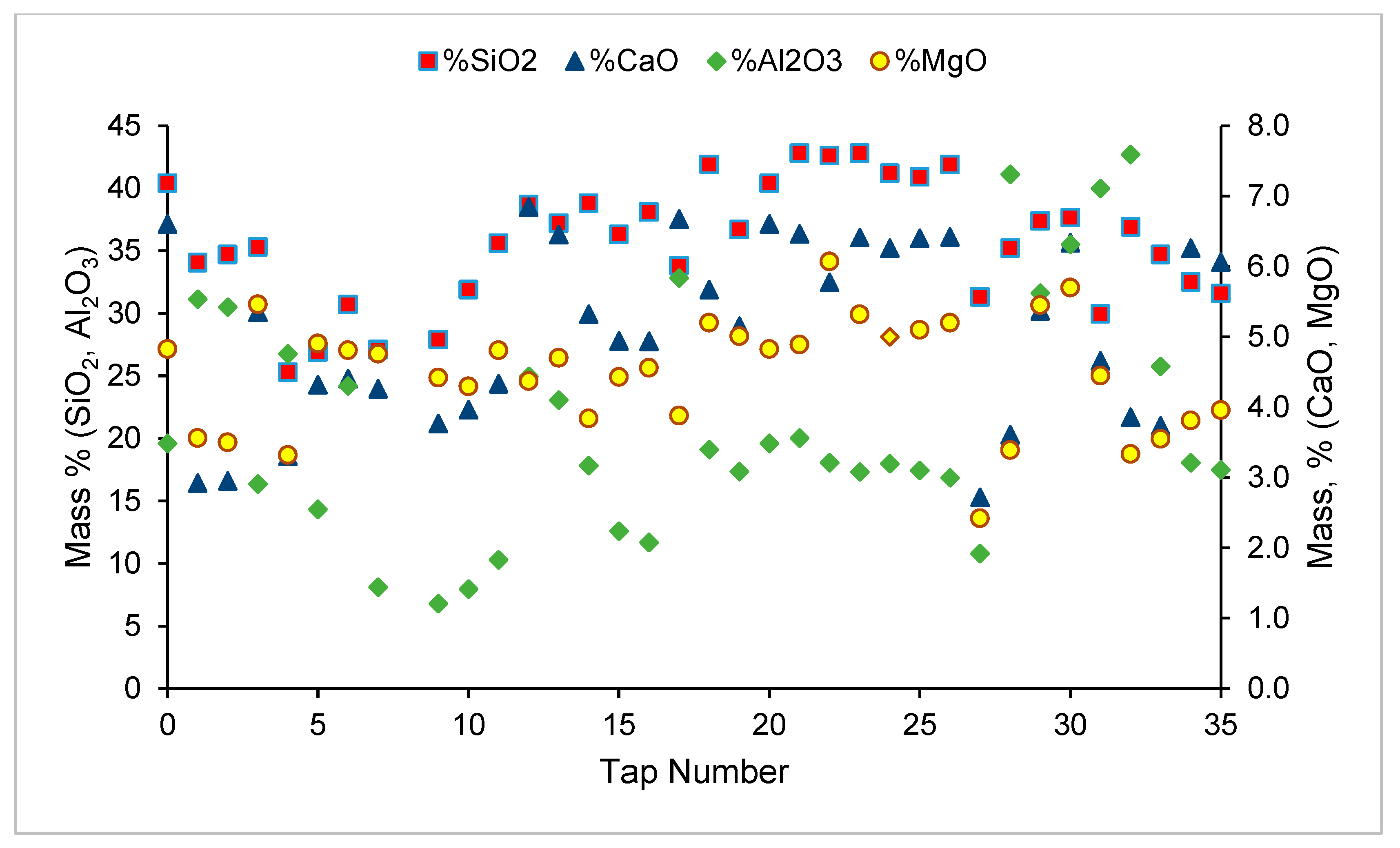
The analysis of the products from the demonstration are shown in Figure 8, Figure 9 and Figure 10 below. The target composition for the alloy was Mn > 75%, Fe > 15% and C > 5. As expected, the amount of MnO in the slag reduced with an increasing Mn content in the alloy. An alloy with the target composition was produced multiple times during both cold and hot feed periods. The fluctuations in the composition of the slag and alloy are due to the power interruptions which affected the thermal stability and had an effect on the recovery and deportment of elements.

3.6. Furnace Operating Parameters (Current, Voltage and Power)

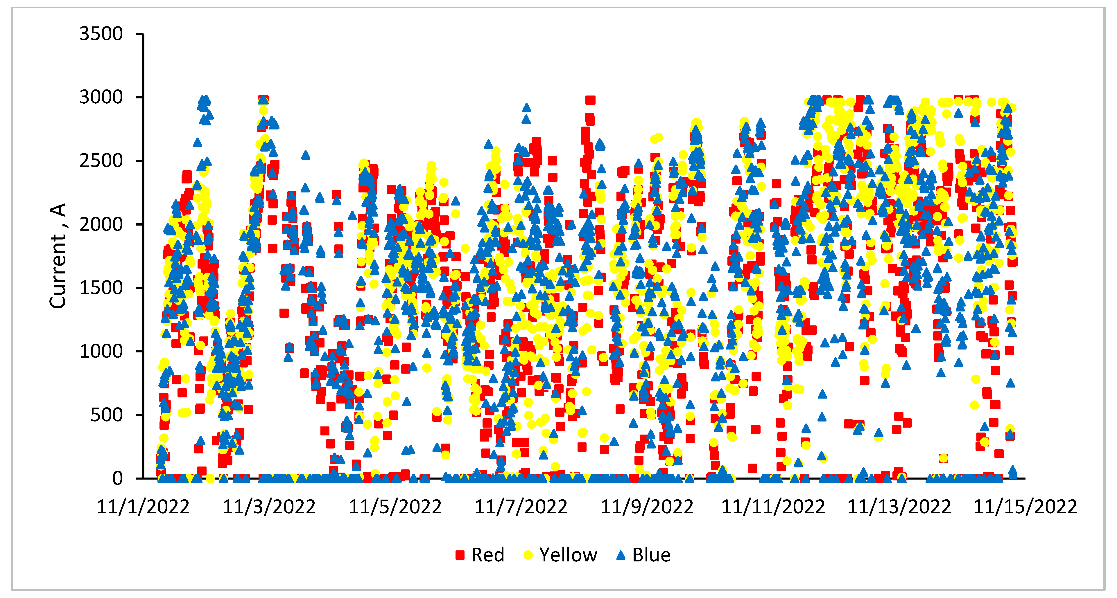
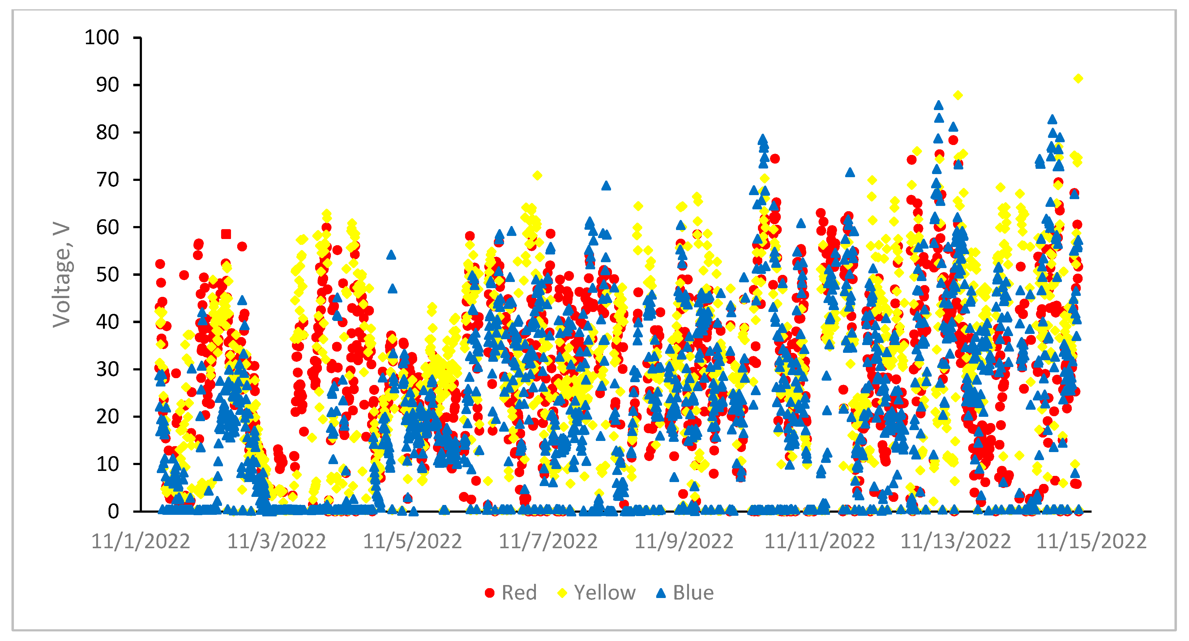
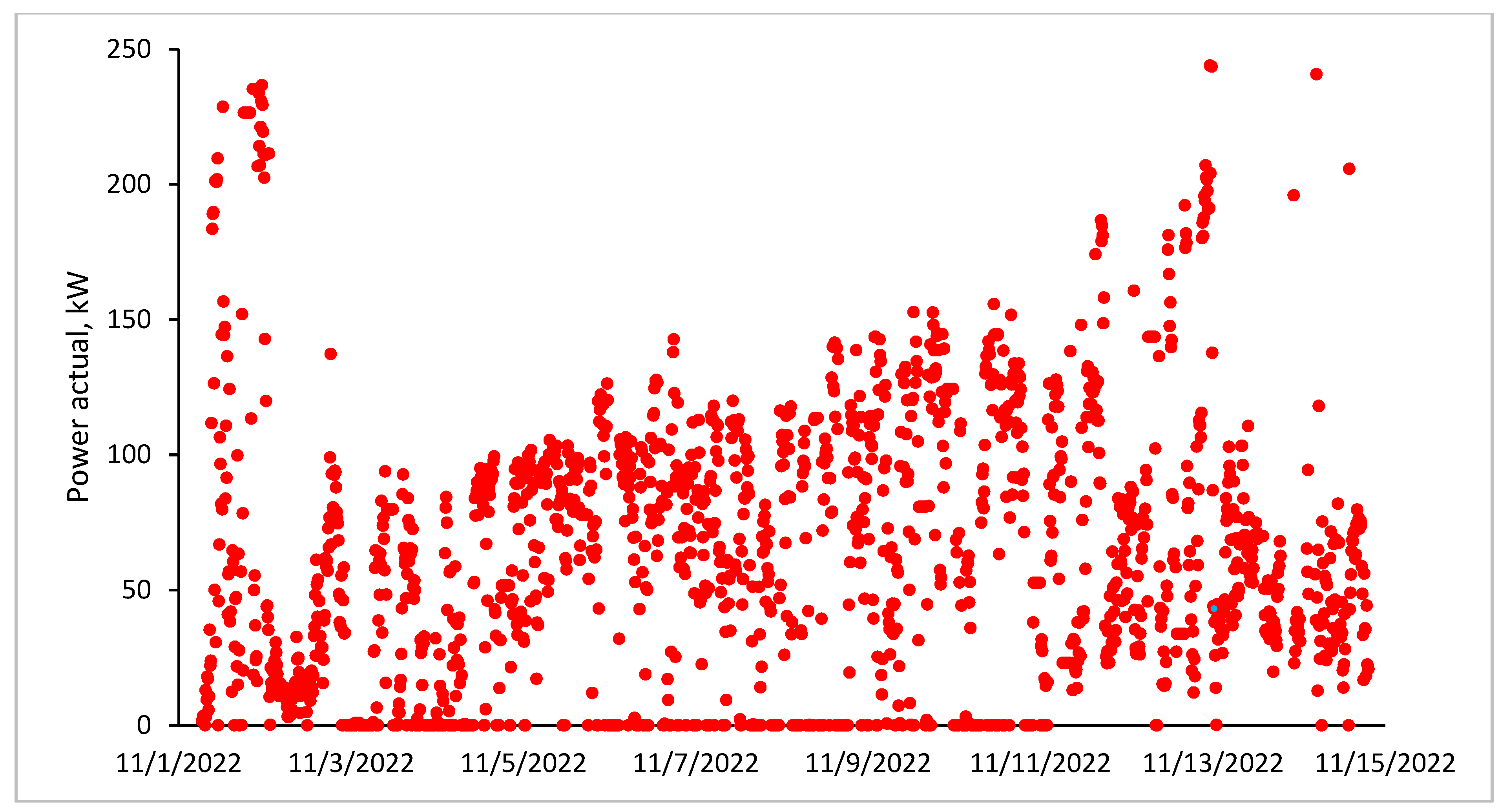
The trends of current, voltage and power from the pilot plant demonstration are shown in Figure 11, Figure 12 and Figure 13. Due to power outages, there were several instances where the current, voltage and power were captured as zero. The average current and process power were 1680 A and 66.3 kW for the duration of demonstration. There were no significant changes in furnace operating parameters seen when operations were switched from cold feed to hot feed.

4. Conclusions

The effect of pre-heating the ore to 600 °C on the SAF energy consumption and CO2 emissions was successfully demonstrated. The effect of a pre-heater on furnace energy consumption and CO/CO2 emissions was determined. The effect on other furnace operation parameters, e.g., heat losses through the different sections of the furnace, furnace electrical data and furnace tapping behavior was also determined. The test work determined an average furnace energy consumption reduction of 22.5% when feeding pre-heated ore instead of cold ore. This is due to the furnace heating the ore from 600 °C instead of room temperature. Consumption also reduced due to the decomposition of carbonated minerals taking place in the kiln, releasing CO2 in the kiln instead of this happening in the furnace burden and participating in the Boudouard reaction. The Bourdouard reaction consumes energy due to its endothermic nature, hence elevated energy consumption during cold feed. An average reduction of 37% in CO2 production was also seen during hot feed compared to cold feed. The reduction in CO2 emissions in hot feed was due to decomposition of carbonated minerals that took place in the rotary kiln instead of the furnace burden. The absence of the Boudouard reaction leads to reduced reductant consumption, which ultimately leads to reduced CO2 emissions during hot feed. Pre-heating the ore increased heat losses through the roof by 300%, while no significant heat loss changes were seen through the side wall and furnace hearth. There were no significant changes in furnace electrical parameters that were seen between cold and hot feed operations.

Author Contributions

Conceptualization, J.S., M.S.M., D.H. and S.P.T.; facility design, J.S., M.S.M., D.H., S.P.T., M.S., D.B. and S.M.; methodology, M.S.M., S.P.T., D.H., S.M., J.S., M.S. and D.B.; formal analysis, M.S.M., S.P.T., D.H. and S.M.; investigation, M.S.M., S.P.T., D.H. and S.M.; resources, S.P.T.; data curation, M.S.M.; writing—original draft preparation, M.S.M.; writing—review and editing, M.S.M., S.P.T., D.H. and S.M.; funding acquisition, J.S. All authors have read and agreed to the published version of the manuscript.

Funding

This study was performed at Mintek and was financially supported by the European Union’s Horizon 2020 PREMA project (funding no: 820561).

Data Availability Statement

Raw research data will be made available on request.

Conflicts of Interest

All authors were employed by the company Mintek. The authors declare no conflict of interest.

References

  1. Zou, Z.; Shao, G.; Ge, Y.; Wang, S.; Xie, Z.; Zhu, Q.; Li, H. From laboratory research to industrial application: A green technology of fluidized mineral processing for manganese dioxide ore reduction. Green Chem. Eng. 2020, 1, 40–47. [Google Scholar] [CrossRef]
  2. Mchabe, D.; Tsebe, S.; Matinde, E. Evaluation of the Effects of Fluidization Conditions on Hydrogen Reduction in Manganese Ore Fines. Minerals 2025, 15, 368. [Google Scholar] [CrossRef]
  3. Banda, W.K.; Steenkamp, J.D.; Matinde, E. An investigation into the wear mechanisms of carbon-and silicon carbide-based refractory materials by silicomanganese alloy. J. S. Afr. Inst. Min. Metall. 2020, 120, 333–344. [Google Scholar] [CrossRef]
  4. Gordon, Y.; Nell, J.; Yaroshenko, Y. Manganese ore thermal treatment prior to smelting. KnE Eng. 2018, 3, 71–86. [Google Scholar] [CrossRef]
  5. Zhao, Q.; Sun, L.; Wang, G.; Luo, C.; Shun, Y.; Yan, K. Novel reduction roasting and leaching method for manganese dioxide ore using FeP slag as the reductant. Hydrometallurgy 2019, 189, 105113. [Google Scholar] [CrossRef]
  6. Julia, N.; Hecquet, A.; Nussbaum, G.; Blancher, S.; Amalric, A. Pre-heating manganese ore in a pilot-scale rotary kiln. In Proceedings of the 16th International Ferroalloys Congress (INFACON XVI), Trondheim, Norway, 27–29 September 2021. [Google Scholar]
  7. PREMA. Available online: https://www.aspire2050.eu/prema (accessed on 24 July 2024).
  8. Olsen, S.E.; Olsen, S.; Tangstad, M.; Lindstad, T. Production of Manganese Ferroalloys; Tapir Academic Press: Trondheim, Norway, 2007. [Google Scholar]
  9. Ringdalen, E.; Gjøvik, J.E.; Larssen, T.A.; Tangstad, M. Pretreatment of manganese ores in different gas-atmospheres-a method to reduce energy consumption and CO2 emissions in Mn-alloy production. In Proceedings of the 16th International Ferro-Alloys Congress (INFACON XVI), Trondheim, Norway, 27–29 September 2021. [Google Scholar]
  10. Pegels, A. Renewable energy in South Africa: Potentials, barriers and options for support. Energy Policy 2010, 38, 4945–4954. [Google Scholar] [CrossRef]
  11. Matinde, E.; Steenkamp, J.D. Metallurgical Overview and Production of Slags; Royal Society of Chemistry: Cambridge, UK, 2021. [Google Scholar]
  12. Lubkoll, M.; Hockaday, S.A.C.; Harms, T.M.; von Backström, T.W.; Amsbeck, L.; Buck, R. Integrating solar process heat into manganese ore pre-heating. In Proceedings of the 5th Southern African Solar Energy Conference, SASEC 2018, Durban, South Africa, 25–27 June 2018. [Google Scholar]
  13. Sambo, S.N.; Hockaday, L.; Seodigeng, T.; Reynolds, Q.G. Numerical and Experimental Study of Packed Bed Heat Transfer on the Preheating of Manganese Ore with Air up to 600 °C. Metals 2025, 15, 269. [Google Scholar] [CrossRef]
  14. Kazdal, T.; Haas-Wittmuess, R.; Richter, S.; Lang, S.; Binder, C.; Reuter, M. Process design for the pre-treatment of manganese ores. In Proceedings of the 16th International Ferroalloys Congress (INFACON XVI), Trondheim, Norway, 27–29 September 2021. [Google Scholar]
  15. Singh, V.; Reddy, K.V.K.; Tripathy, S.K.; Kumari, P.; Dubey, A.K.; Mohanty, R.; Satpathy, R.R.; Mukherjee, S. A sustainable reduction roasting technology to upgrade the ferruginous manga-nese ores. J. Clean. Prod. 2021, 284, 124784. [Google Scholar] [CrossRef]
  16. Moholwa, M.S.; Tsebe, S.P.; Hayman, D.A.; Bezuidenhout, P.J.A.; Sitefane, M.B.; Steenkamp, J.D. Effect of ore pre-heating on furnace operation in high carbon ferromanganese production—lessons learnt from pilot-scale test work. In TMS Annual Meeting & Exhibition; Springer Nature Switzerland: Cham, Switzerland, 2023; pp. 237–252. [Google Scholar]
  17. Hockaday, L.; Dinter, F.; Reynolds, Q.G.; McGregor, C. Evaluation of solar thermal pretreatment of car-bonate-rich manganese ores in high-carbon ferromanganese production through dynamic process modelling. J. S. Afr. Inst. Min. Metall. 2024, 124, 763–775. [Google Scholar] [CrossRef]
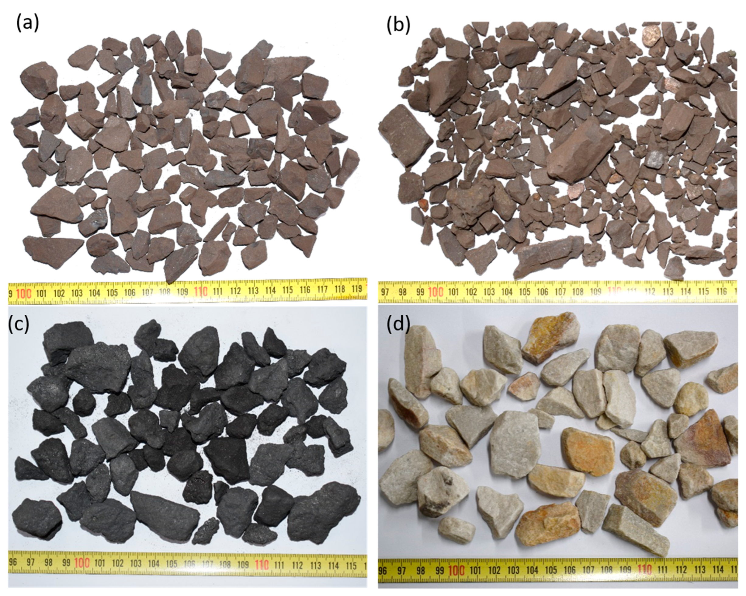
Figure 1. Photographs of raw materials representing (a) Ore #1, (b) Ore #2 (c) coke and (d) Quartz.
Minerals 15 00968 g001
Figure 2. Particle size distribution of raw materials used in the test work.
Minerals 15 00968 g002
Figure 3. XRD diffractogram for Ore #1.
Minerals 15 00968 g003
Figure 4. XRD diffractogram for Ore #2.
Minerals 15 00968 g004
Figure 5. General arrangement of the cold and hot feed system, furnace shell and ladle [16].
Minerals 15 00968 g005
Figure 6. Furnace start-up heel.
Minerals 15 00968 g006
Figure 7. Furnace heat losses for the shell, hearth and roof.
Minerals 15 00968 g007
Figure 8. Slag analysis for Mn and Fe.
Minerals 15 00968 g008
Figure 9. Slag analysis for SiO2, Al2O3, Ca and MgO.
Minerals 15 00968 g009
Figure 10. Metal analysis.
Minerals 15 00968 g010
Figure 11. Current on all three electrodes.
Minerals 15 00968 g011
Figure 12. Voltage on all three electrodes.
Minerals 15 00968 g012
Figure 13. Furnace power.
Minerals 15 00968 g013
Table 1. Chemical composition of the raw materials (wt%).
MnFeMgOAl2O3SiO2CaOCSFe2O3Vol.AshMC
Ore #136.73.83.30.55.215.4
Ore #237.44.53.10.66.215.2
Reductant 0.24.15.90.584.41.120.932.512.40.2
Quartz 99.7
Table 2. Bulk mineralogical compositions of Ore #1 and Ore #2, in wt%, as measured by the QXRD.
MineralIdeal Chemical FormulaOre #1Ore #2
Quartz SiO21.21.3
BrauniteMn6SiO1232.234.3
HausmanniteMn2O414.520.8
KutnohoriteCa(Mn,Mg,Fe)(CO3)218.412.0
Jacobsite(Mn,Fe,Mg)(Fe,Mn)2O41.23.8
CalciteCaCO314.414.5
DolomiteCaMg(CO3)212.410.2
HematiteFe2O33.13.2
LizarditeMg3Si2O5(OH)4<1<1
Todorokite(Na,Ca,K)2(Mn)6O12·3–4.5(H2O)2.5-
Table 3. Summary of the gas analysis during the cold feed and hot feed period.
ReadingCOCO2H2O2N2
ColdHotColdHotColdHotColdHotColdHot
120.225.415.69.966.546.992.412.2312.611.6
219.524.214.29.095.967.032.592.4413.212.4
321.525.015.79.536.127.112.962.3512.012.2
419.723.315.8105.997.563.022.6312.012.0
Standard dev0.90.90.80.40.30.30.30.20.60.3
Average20.224.515.39.656.157.172.752.4112.512.1
Table 4. Overall material balance for the campaign.
FeedIN, kgProductsOUT, kg
UMK ore4651Slag4087
Kudumane ore3026Metal1733
Quartz1081Off-gas Dust510
Coke1667Dig-out Metal80
Start-up Heel125Dig-out (unprocessed material)498
Electrodes566Electrodes96.3
Total11,115Total7004
Table 5. Overall elemental mass balance.
Recovery, mass %
Product streamMnFeSiCCaMg
Metal48865400
Slag31157508149
Dust7150313
Total861038548562
Distribution, mass %
Product streamMnFeSiCCaMg
Metal558469800
Slag37158829679
Dust8160421
Total100100100100100100
Disclaimer/Publisher’s Note: The statements, opinions and data contained in all publications are solely those of the individual author(s) and contributor(s) and not of MDPI and/or the editor(s). MDPI and/or the editor(s) disclaim responsibility for any injury to people or property resulting from any ideas, methods, instructions or products referred to in the content.