Article

Humped Flow Channel in Drum Magnetic Separator Leads to Enhanced Recovery of Magnetic Seeds in Magnetic Flocculation Process

1
School of Minerals Processing and Bioengineering, Central South University, Changsha 410083, China
2
Institute of Resources Utilization and Rare Earth Development, Guangdong Academy of Sciences, Guangzhou 510650, China
3
School of Environmental Science and Engineering, Processing and Bioengineering, Guangdong University of Technology, Guangzhou 510006, China
*
Author to whom correspondence should be addressed.
Minerals 2025, 15(7), 732; https://doi.org/10.3390/min15070732
Submission received: 24 May 2025 / Revised: 3 July 2025 / Accepted: 8 July 2025 / Published: 12 July 2025
(This article belongs to the Special Issue Advances in the Theory and Technology of Physical Separation)

Abstract

This study examines the effect of smooth and humped flow channels on the recovery of industrial magnetic seeds in a drum magnetic separator. The results demonstrate that under varying feeding slurry quantities and drum rotational speeds, the humped channel consistently achieves higher recovery rates compared with the smooth channel, with an improvement of up to 3%. Scanning electron microscopy and vibrating sample magnetometry analyses of the samples reveal the presence of a small amount of impurities (predominantly consisting of elements, such as Al, Si, and Ti) in the industrial magnetite magnetic particles. These impurities exhibit lower magnetization, leading to reduced capture efficiency in the conventional smooth-channel drum magnetic separator. Simulations of the magnetic field, flow field, and particle trajectory indicate that the magnetic field force at the bottom of the smooth channel is only 0.6 kg2/(m·s4·A2), i.e., approximately 18 times lower than that at the roller surface. The incorporation of a humped channel shifts the impure magnetic seeds from a region with low magnetic field force to a region with higher magnetic field force, significantly enhancing the capture efficiency of the impure magnetic seeds.

1. Introduction

Magnetic flocculation wastewater treatment technology can be used as a novel approach to water treatment that combines the advantages of traditional flocculation technology and magnetic separation technology [1,2]. It has gained widespread attention and application in recent years [3]. The principle of this technology is the addition of magnetic seeds at its core, which, under the network-trapping action of flocculants, aggregate with suspended pollutants in the wastewater to form magnetic flocs. These magnetic flocs are then separated from the water through gravity settling or the application of an external magnetic field by utilizing the high density or high magnetic properties of the magnetic seeds [4,5]. This process achieves the purification of water and the removal of pollutants. This technology effectively accelerates the settling speed of flocs, enhances the removal efficiency of solid particles in wastewater, and addresses issues that are commonly encountered in traditional sedimentation methods, such as low surface load, slow settling speed, large land occupation, and significant water quality fluctuations, through rapid separation via an external magnetic field. Furthermore, magnetic flocculation technology exhibits good selectivity and adjustability, enabling the selection of different flocculants based on the characteristics of various water qualities and pollutant types and thus optimizing the treatment effect [6]. This technology has demonstrated superior performance in removing heavy metal ions [7], organic pollutants [8], oil [9], bacteria [10], and other substances [11] from water, making it particularly suitable for the treatment of difficult-to-handle or cost-prohibitive industrial wastewater and municipal sewage.
To reduce treatment costs and enhance the environmental protection of the system in this process, magnetic seeds must be efficiently recovered and reused using magnetic separation equipment. Therefore, improving the structure of magnetic separation equipment and enhancing the recovery of magnetic seeds are of considerable importance for the advancement of this technology. The literature has reported on magnetic seed recovery equipment, which includes electromagnetic high-gradient [12], disc-permanent [13], and drum-permanent magnetic separators [14]. The first is suitable for recovering fine and weakly magnetic seeds (e.g., modified magnetic seeds, such as limonite, hematite, and ilmenite), while the latter two are suitable for recovering coarser and stronger magnetic seeds (e.g., magnetite, steel slag, and pure iron powder). Tang et al. [15] investigated the influence of separation chamber shape in dry magnetic separators, demonstrating that a wavy-shaped separation chamber (WSC) promotes airflow turbulence and vortex generation. This design effectively disperses aggregated fine particles, improving the recovery of magnetite and high-grade intergrowths while enhancing the overall separation efficiency. Their work highlights the significant role of chamber shape in manipulating particle behavior and separation outcomes. Wang et al. [16] focused on optimizing magnetic field gradients in a wet low-intensity magnetic separator (LIMS), proposing an innovative precise low-intensity magnetic separator (PLIMS) with a gradient magnet assembly (GMA). The GMA is designed to gradually increase the remnant flux density along the slurry flow direction, enabling “precise magnetic force” application to magnetic particles. This approach balances the capture of high-liberation magnetite and low-grade intergrowths, outperforming uniform magnet assemblies (UMAs) in separation performance. Their work emphasizes the potential of tailored magnetic field gradients to enhance both concentrate grade and recovery efficiency. At present, the magnetic seeds that are widely used in industrial wastewater and municipal sewage treatment are strongly magnetic magnetite, and the primary recovery equipment is the drum magnetic separator [4]. Magnetite exhibits advantages, such as its abundant sources, simple preparation process, low production cost, and high recycling rate, compared with other magnetic seeds. However, a relatively high loss rate of magnetic seeds is frequently observed when using traditional drum magnetic separators for mineral processing to recover magnetic seeds [17], inadvertently increasing the cost of wastewater treatment and possibly leading to secondary pollution of the water.
The current study focuses on the issue of magnetic seed loss that is commonly encountered in traditional drum magnetic separators through conducting research on optimizing the flow channel structure. First, industrial condition experiments were performed to compare the effects of humped and traditional smooth channels on magnetic seed recovery. Subsequently, scanning electron microscopy (SEM) and vibrating sample magnetometry (VSM) were conducted to analyze the products of industrial magnetite magnetic seed separation and determine the primary causes of high seed loss rates. Finally, magnetic field and flow field simulations, particle body force calculations, and finite-/discrete-element coupled particle trajectory simulations were utilized to reveal the influence mechanism of the shape of a flow channel on magnetic seed recovery. This research will provide theoretical and practical guidance for enhancing the recovery of magnetic seeds in the magnetic flocculation process.

2. Materials, Equipment, and Methods

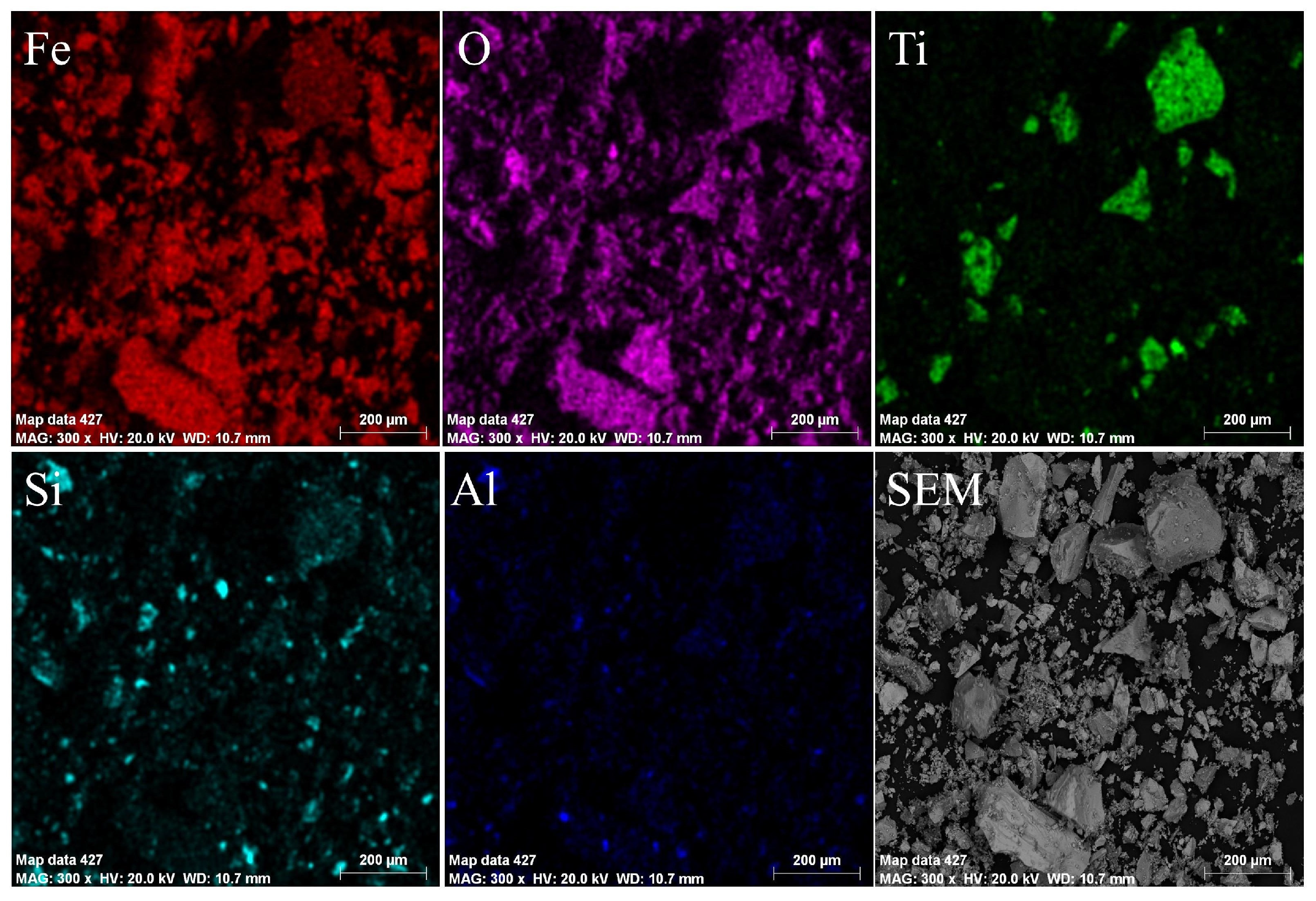
2.1. Raw Magnetic Seeds

The raw magnetic seeds used in this study originated from an industrial magnetite sample used in a wastewater treatment company in Zhejiang Province (Taizhou, China). The SEM analysis of this sample is shown in Figure 1. Figure 1a indicates that the overall particle size distribution of the magnetic seeds is broad, with a minimum particle size of 6.41 μm and a maximum particle size of 244.20 μm, demonstrating a considerable size variation. Figure 1b shows the presence of a few impurities in the magnetic seeds (as indicated by the dark particles at Point 1), which are distinctly different from the magnetite (as indicated by the light particles at Point 2). Figure 1c reveals that the impurities at Point 1 contain other excessive elements, such as Mg, Al, Si, Ca, and Ti, in addition to the major elements Fe and O. The presence of these elements significantly reduces the proportion of Fe, thus weakening the magnetic properties of the particles and increasing the loss rate of the magnetic seeds during subsequent magnetic capture processes. Figure 1d shows that the Fe mass fraction in the magnetite particles at Point 2 is 69.27%; therefore, the theoretical purity of this magnetite is 95.68%, indicating relatively high purity. Figure 2 further provides the energy-dispersive X-ray spectroscopy (EDS) mapping spectra of the raw magnetic seeds, wherein the distributions of Ti and Si are clearly visible. Ti exhibits a distinct granular distribution, while Si presents a scattered point distribution. Combined with the distribution of the major elements Fe and O, the impurities in these magnetic seeds can be presumed to exist in the form of ilmenite monomers and silicate mineral intergrowths. Compared with magnetite, ilmenite and silicate minerals have a relatively lower magnetic susceptibility. The presence of these weakly magnetic impurity mineral phases is the primary reason for the high loss rate of industrial magnetite magnetic seeds during their reuse.

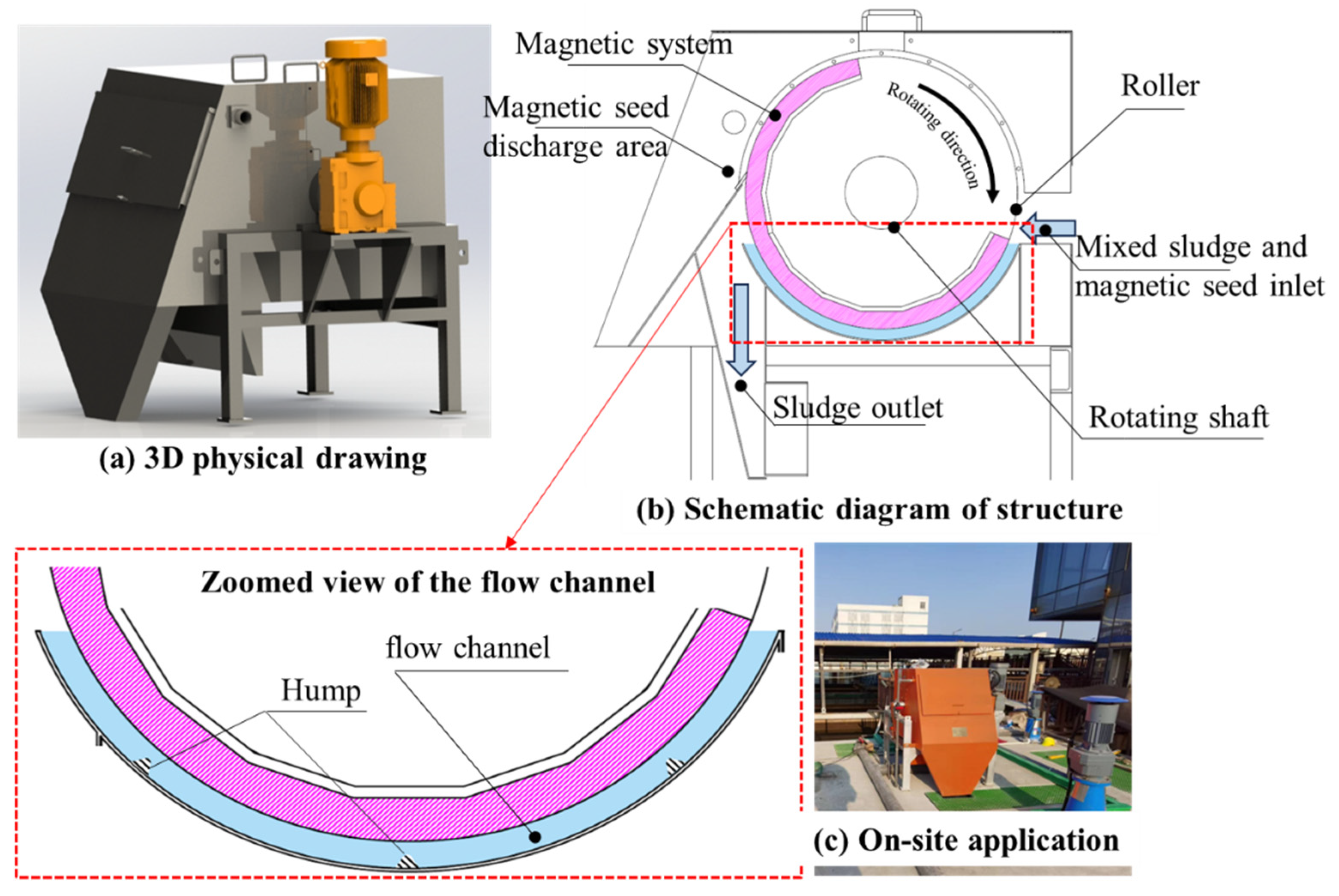
2.2. Drum Magnetic Separator and Separation Principle

For the magnetic seed recovery equipment, we used a drum-type magnetic separator developed by our team. Its 3D physical drawing, structure diagram, and on-site application are depicted in Figure 3. As seen in Figure 3b, this magnetic separator consists of several major components, including a magnetic system, a rotating roller, a slurry inlet, a sludge outlet, and a magnetic seed discharge area. The magnetic system uses NdFeB permanent magnets (N42), which are arranged in an alternating N–S–S–N magnetic pole structure. The flow channels are designed with both smooth and humped types. The diameter of the roller is 600 mm, and the depth of the flow channel is 30 mm. The humped-type channel features three evenly spaced humps on the bottom wall, as shown in the zoomed view of the flow channel in Figure 3b.
The difference in motion trajectories of the magnetic seeds and sludge within the flow channel enables their separation and the reuse of the magnetic seeds. The motion trajectory of particles of different types is primarily determined by the combined body forces acting on particles, such as magnetic, fluid drag, gravitational, centrifugal, and frictional forces, as shown in Figure 4. When the magnetic seeds and sludge flow through the channel of the magnetic separator, the magnetic force acting on the magnetic seed particles must be greater than the combined force of the competing forces (e.g., gravity and fluid drag) [15], causing the particles to be stuck onto the roller surface and then collected in the magnetic seed discharge area for reuse after the drum’s rotation. By contrast, the magnetic force acting on the sludge particles is smaller than the combined forces of gravity and fluid drag, causing the sludge particles to flow out through the sludge outlet with the fluid. Particles that have already become stuck onto the roller surface are also subject to centrifugal and frictional forces in addition to magnetic, fluid drag, and gravitational forces due to the drum’s rotation. This situation can continue to clean the sludge carried with the magnetic seeds from the roller surface. In practice, researchers frequently assume microfine particles to be spherical to simplify the calculation of body forces [18]. The corresponding magnetic force Fm, fluid drag force Fd, gravitational force Fg, centrifugal force Fc, and frictional force Ff can be calculated using Equations (1)–(5) [19].
The magnetic force acting on particles can be expressed as follows:
F m = 4 3 π R 3 κ B g r a d B μ 0 ,
where R is the particle radius, μ0 is the vacuum permeability, κ is the volume susceptibility, and B and gradB are the induced magnetic field strength and gradient, respectively. The units and specific values of all parameters in this study’s equations are provided in Table 1 and Table 2.
In addition, the fluid drag, gravitational, and centrifugal forces acting on the particles are, respectively, given as follows:
F d = 6 π η R Δ v ,
F g = 4 3 π R 3 ρ P ρ f g ,
F c = 4 3 π R 3 ρ P ω 2 a ,
where η is the viscosity of air, ∆v is the relative velocity between a particle and airflow, ρP is the density of a particle, ρf is the density of fluid, ω is the rotational angular velocity of the roller, a is the radius of the roller, and g is the acceleration due to gravity. Friction is the force acting in the reverse direction of particle movement, which is a function of normal force and the coefficient of friction (f). It can be expressed as follows:
F f = f F m F c F g cos θ .

2.3. Experimental Methods

This experiment primarily investigated the effect of variations in flow channel shape on the capture of magnetic seeds. Therefore, we disregarded the effect of sludge on magnetic seed capture during the experimental process. In the experiment, 10 L of clean water was first added to a stirring tank, followed by the addition of 1000 g of the raw magnetic seeds. Then, the water and the seeds were thoroughly mixed. The flow channel of the drum magnetic separator was then filled with clean water, and the drum speed was adjusted to set values (12, 16, 24, and 32 r/min). Thereafter, a pump was used to feed the prepared slurry from the stirring tank into the magnetic separator at the desired flow rates (20, 30, 40, and 50 m3/h) for each smooth and humped channel. Once the slurry had been fully fed, the magnetic seeds that escaped with the clean water were collected. The corresponding mass was recorded after drying and weighing. Subsequently, representative samples of the raw and escaped magnetic seeds were selected for comparative analysis by using SEM and VSM to identify the causes of magnetic seed loss. The method for calculating the recovery rate of the magnetic seeds for different flow channels was as follows:
ε = 1 M e M T × 100 % ,  
where Me is the mass of the escaped magnetic seeds, and MT is the total mass of the feeding magnetic seeds.

3. Experimental Results

3.1. Experimental Conditions

In the comparison experiment of feeding slurry quantity, the rotating speed of the roller was fixed at 16 r/min, and slurry quantity was adjusted separately in the smooth and humped channels. The experimental results are presented in Figure 5. As shown in the figure, the recovery of the magnetic seeds in both channels slowly decreased within the range of 20 m3/h to 30 m3/h with the feeding slurry quantity increasing from 20 m3/h to 50 m3/h, and then rapidly decreased when the quantity exceeded 30 m3/h. In particular, recovery dropped from the initial 99.78% to 97.90% in the smooth channel, with a significant decrease. The increase in quantity raised the superficial velocity in the channel, increasing the drag force of the fluid, which affected the capture of the magnetic seeds. Compared with that in the smooth channel, magnetic seed recovery in the humped channel was significantly higher, with the advantage becoming more pronounced as the quantity increased. At quantities of 30 m3/h and 50 m3/h, the recovery rates of magnetic seeds in the humped channel were 99.90% and 99.05%, respectively, which were 0.22% and 1.15% higher than those in the smooth channel. The humped channel can effectively mitigate the effect of flow fluctuations on magnetic seed capture during the wastewater treatment process.
In the comparison experiment under varying roller rotating speed conditions, rotating speed was adjusted in the smooth and humped channels with a fixed feeding slurry quantity of 30 m3/h. The experimental results are presented in Figure 6. As can be observed in the figure, the recovery of the magnetic seeds in both channels consistently decreased as the rotating speed increased from 12 r/min to 32 r/min, with a more pronounced decline at higher speeds. In particular, the recovery rate in the smooth channel decreased from an initial 99.93% to 94.59%, i.e., a reduction of 5.34%. The increase in rotating speed leads to a higher centrifugal force acting on the particles within the channel, thus intensifying the tendency of the particles to move toward the bottom wall of the channel and affecting the capture of the magnetic seeds. Compared with that in the smooth channel, magnetic seed recovery in the humped channel was significantly higher, and the advantage became more evident with higher rotating speeds. At a rotating speed of 16 r/min and 32 r/min, recovery rates in the humped channel were 99.90% and 97.59%, respectively, which were 0.22% and 3.00% higher than those in the smooth channel. Therefore, the humped channel allows for a moderate increase in roller rotating speed without compromising the magnetic seed capture, thus enhancing the processing capacity of the drum magnetic separator.

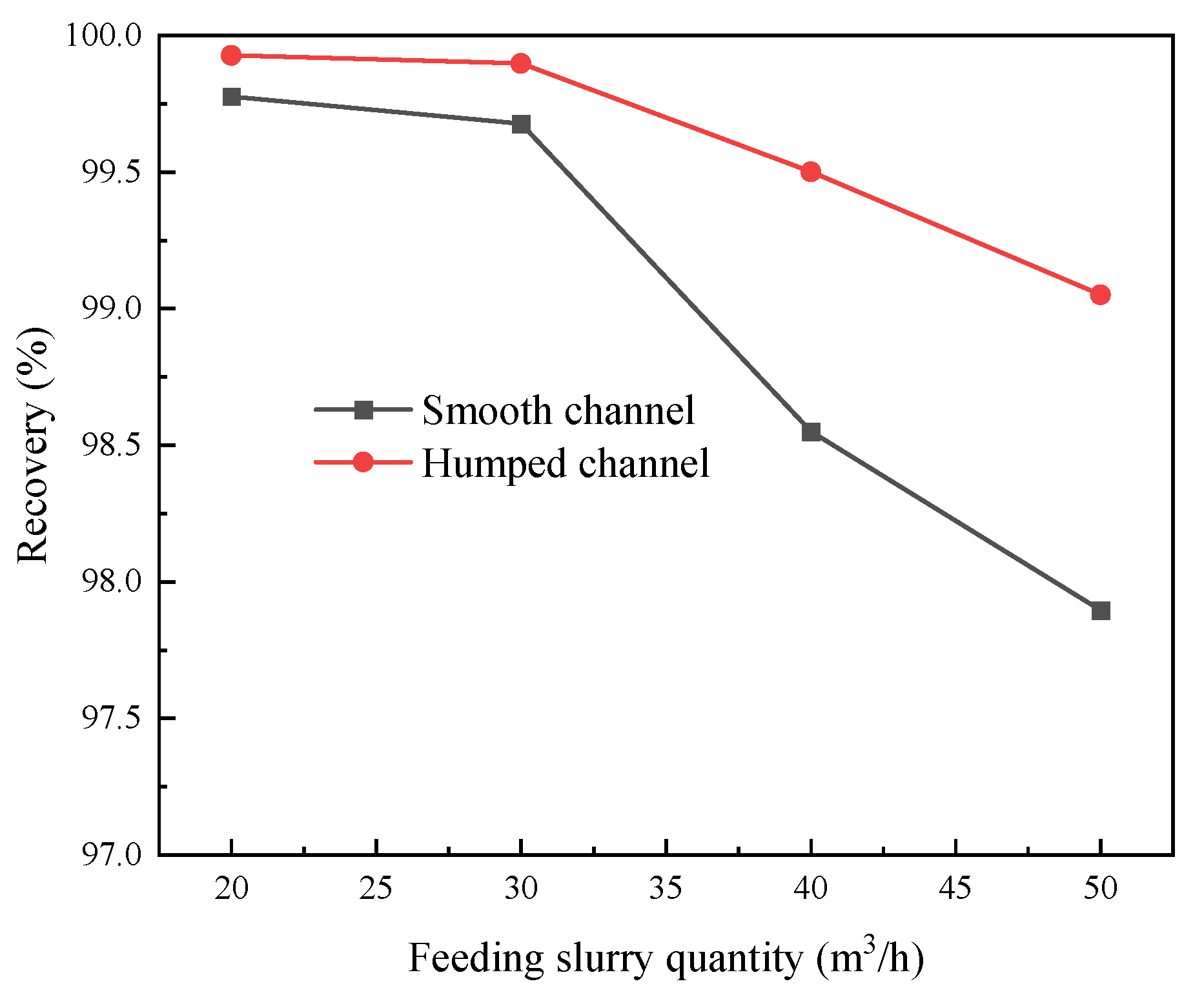
3.2. Product Analysis

SEM and VSM analyses of the raw and escaped magnetic seeds were conducted under the following conditions: feeding slurry quantity of 30 m3/h and roller rotating speed of 16 r/min. The results are presented in Figure 7, Figure 8 and Figure 9. As depicted in Figure 7, the escaped magnetic seeds are finer in size compared with the feeding raw magnetic seeds. This discrepancy is primarily due to the fact that the magnetic force acting on the particles is proportional to the cube of particle size. That is, smaller particles experience a weaker magnetic force, making them less likely to be stuck onto the roller surface. Further observation of the particle size distribution of the escaped magnetic seeds under the smooth and humped channels reveals that the escaped magnetic seeds exhibit a wide range of sizes in the smooth channel, with some larger particles (>100 μm) still escaping. By contrast, particle size distribution in the humped channel is more uniform, with no significant presence of large particles. This finding suggests that the humped channel increases the capture probability of large magnetic seeds and effectively prevents their loss due to imbalances between magnetic and competing forces (e.g., gravitational and fluid drag forces).
Figure 8 further illustrates the EDS mapping spectra of the samples. Based on this figure, the content distribution of Al, Ti, and Si elements in the escaped magnetic seeds is significantly higher than that in the feed magnetic seeds, suggesting that the escaped magnetic seeds are primarily particles with higher impurity content and relatively weaker magnetic properties, making them more difficult to capture. Furthermore, the content of Al, Ti, and Si elements in the escaped magnetic seeds from the humped channel is generally higher than that in escaped magnetic seeds from the smooth channel, indicating that the humped channel enhances the capture of fine, high-purity magnetite particles, thus alleviating the loss of effective magnetic seeds.
To further investigate the effect of impurity elements, such as Al, Si, and Ti, on the magnetic properties of the magnetic seeds, Figure 9 presents the magnetic susceptibility curves of the feeding and escaped magnetic seeds. Evidently, the susceptibility of the escaped magnetic seeds, which contain higher levels of impurity elements, is significantly lower than that of the feed magnetic seeds. In addition, the susceptibility of the escaped magnetic seeds in the humped channel is lower than that of those in the smooth channel. Therefore, based on the aforementioned results, a conclusion can be drawn that the impurity elements Al, Si, and Ti present in industrial magnetite magnetic seeds affect the purity of certain magnetite particles, reducing their magnetic properties and consequently leading to a higher magnetic seed loss rate. The use of the humped channel in the drum magnetic separator, replacing the traditional smooth channel, helps increase the capture of magnetic seeds and reduce the loss of weakly magnetic impurity seeds.

4. Analysis of Mechanism

For this analysis, we performed a theoretical study on smooth and humped channels by using methods such as finite-element magnetic field simulation [21], computational fluid dynamics simulation [22], numerical estimation of particle body forces, and discrete-element particle trajectory simulation [20], providing a detailed explanation of the enhancement mechanism of magnetic seed capture by the humped channel.

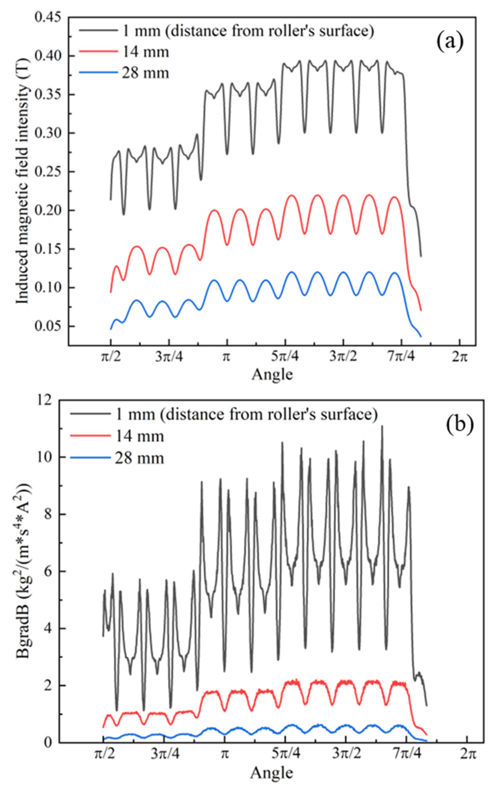
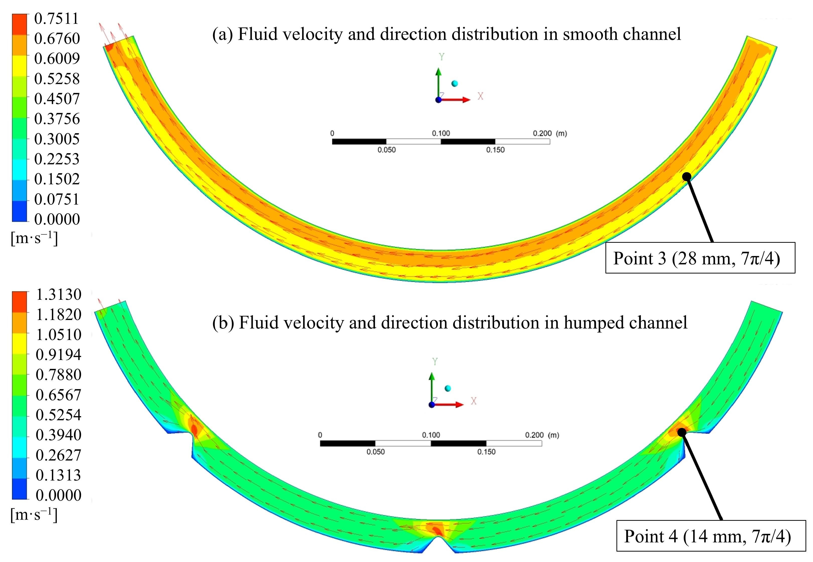
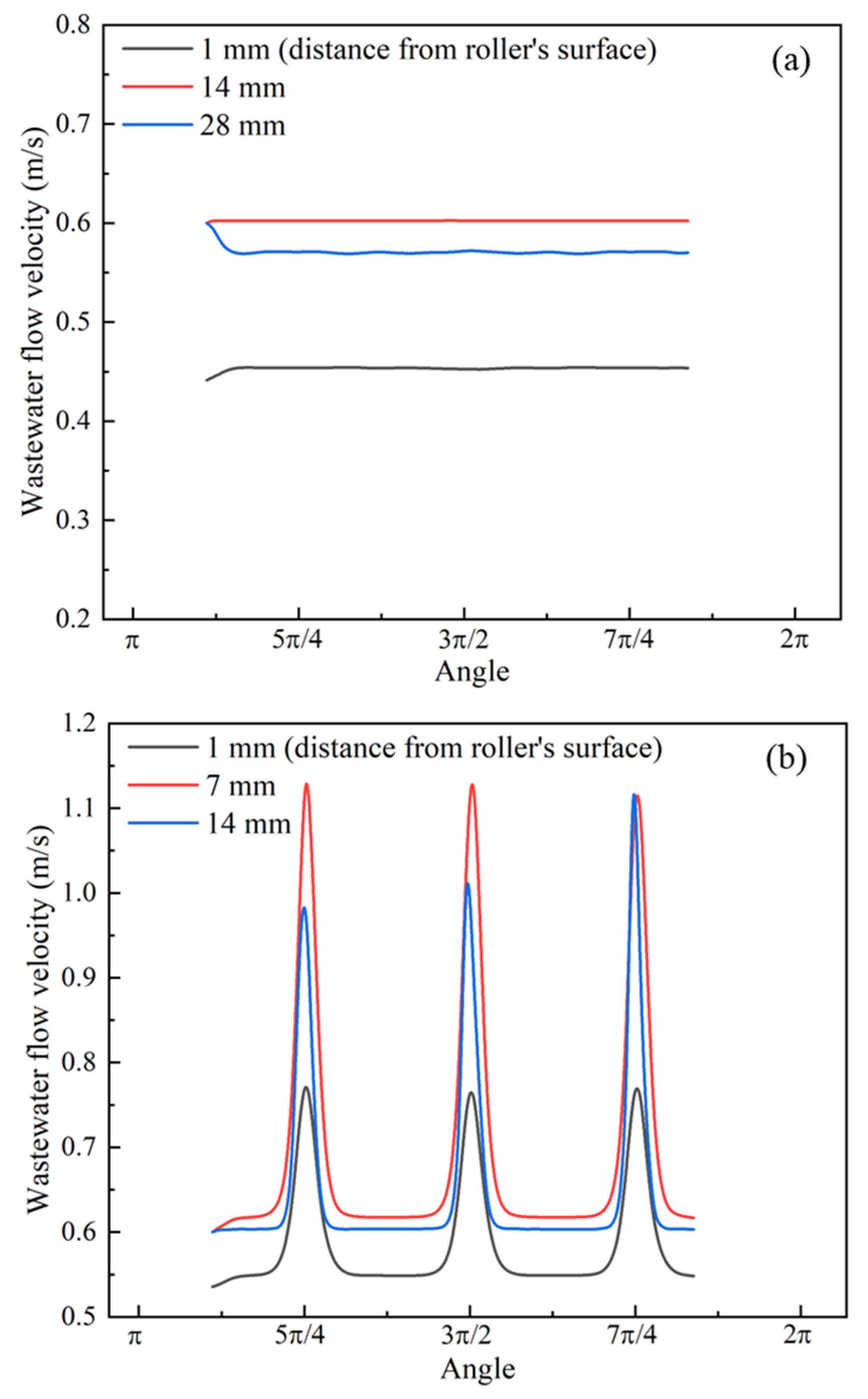
4.1. Simulation of Magnetic and Flow Fields

The magnetic field distribution obtained via finite-element magnetic field simulation is shown in Figure 10 and Figure 11. Figure 10 presents the distribution of the induced magnetic field strength around the magnetic system of the drum magnetic separator, while Figure 11 illustrates the magnitude curves of the induced magnetic field strength and magnetic field force at different distances from the roller surface. The dashed arcs in Figure 10 represent the positions of 1, 14, and 28 mm away from the surface, in which the total depth of the flow channel is 30 mm. From Figure 10, the induced magnetic field strength in the flow channel decreases gradually in the radial direction. In the region within 14 mm of the roller surface, the induced magnetic field strength is consistently greater than 0.15 T, but the induced magnetic field strength is approximately 0.05 T, which is relatively low, near the bottom wall of the channel. The specific magnitude of the induced magnetic field strength at different dashed arcs is shown in Figure 11. Along the circumferential direction of the magnetic system, the induced magnetic field strength and the magnetic field force exhibit a distinct alternating pattern of peaks and valleys, with more pronounced fluctuations closer to the roller surface. At a distance of 1 mm from the roller surface, the maximum induced magnetic field strength and the magnetic field force reach 0.39 T and 11.0 kg2/(m·s4·A2), respectively. At 14 mm, these values are reduced to 0.21 T and 2.20 kg2/(m·s4·A2), while at 28 mm, they are further reduced to 0.12 T and 0.60 kg2/(m·s4·A2), respectively. The reduction in the induced magnetic field strength and the magnetic field force is significant, indicating that magnetic seed particles closer to the roller surface experience stronger magnetic forces.
The flow field distributions in the smooth and humped channels, which are obtained through computational fluid dynamics simulation, are shown in Figure 12 and Figure 13, respectively. Figure 12 presents the flow field contour map and vector distribution, while Figure 13 shows the magnitude curves of flow velocity at different heights from the roller surface. As seen in Figure 12a, velocity distribution in the smooth channel is relatively uniform. Overall flow velocity in the channel fluctuates around a superficial velocity of 0.6 m/s, with the deviation being less than 0.1 m/s. In this channel, the magnetic particles move in a relatively regular circumferential motion along the streamlines after entering the flow path. The magnetic particles at the bottom of the channel are unable to transition from regions of low magnetic field force to regions of high magnetic field force, increasing the loss rate. By comparison, the presence of humps disrupts the original regular circumferential flow in the humped channel shown in Figure 12b. At each hump, the channel narrows, and the fluid at the bottom moves upward along the hump, providing kinetic energy for the transition of particles in the magnetic field force, and potentially increasing the probability of magnetic particle capture. The specific flow velocity magnitudes at 1, 14, and 28 mm away from the roller surface in the smooth and humped channels are shown in Figure 13a,b, respectively. As can be observed along the circumferential direction, although the introduction of humps facilitates the transition of magnetic particles toward higher-magnetic-force regions, it also leads to localized velocity surges. Compared to the smooth channel with velocity fluctuations between 0.45 m/s and 0.60 m/s, the maximum velocity in the humped channel can reach 1.14 m/s. Whether it enhances magnetic seed capture still requires further evaluation through the estimation of body forces acting on the particles.

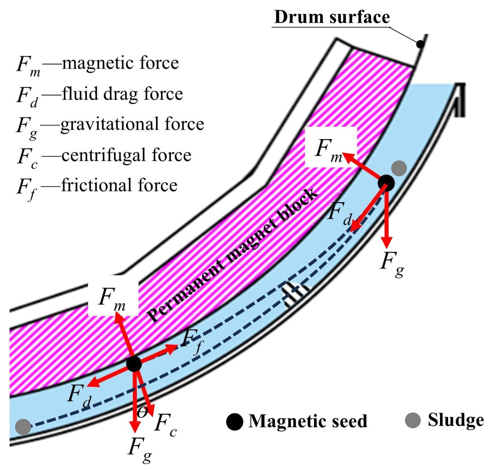
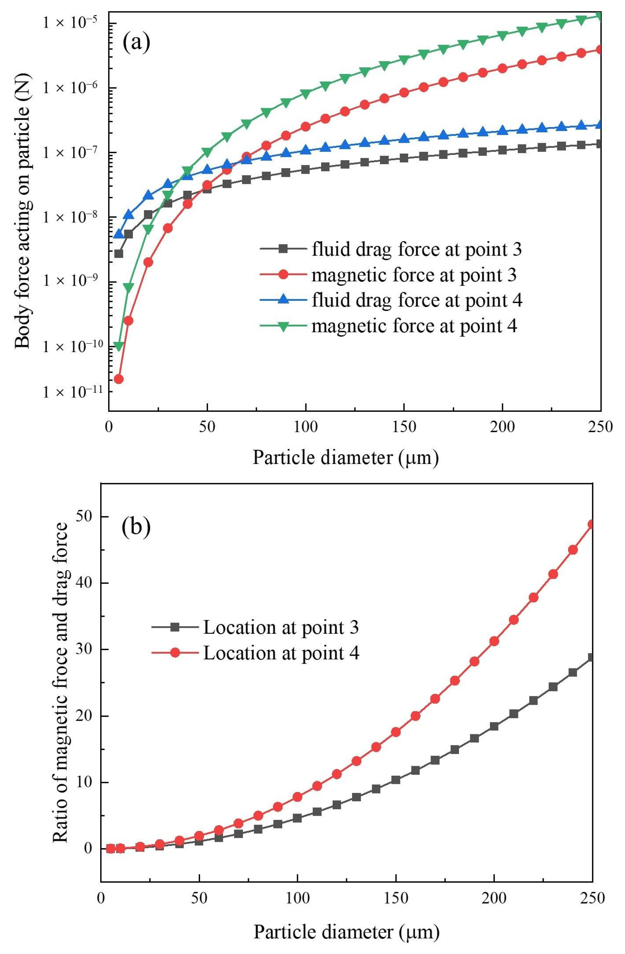
4.2. Estimation of Body Forces Acting on Particles

Variation in the shape of the flow channel affects the magnetic force and fluid drag acting on the impure magnetic seeds, while body forces, such as gravitational, centrifugal, and friction forces, remain unchanged. Therefore, only the magnetic and fluid drag forces at Points 3 and 4, as indicated in Figure 12, were calculated using Equations (1) and (2). The specific magnitudes of parameters in these equations are listed in Table 1, and the results are presented in Figure 14. As seen in Figure 14a, the magnetic and fluid drag forces at Point 3 (in the smooth channel) for particles of different sizes are smaller than those at Point 4 (in the humped channel). For particles with a size of 38 μm, the magnetic and fluid drag forces at Point 3 are 1.37 × 10⁻⁸ N and 2.06 × 10⁻⁸ N, respectively, with the magnetic force being smaller than the drag force, causing the impure magnetic seeds to tend to escape. By contrast, the magnetic and fluid drag forces are 4.57 × 10⁻⁸ N and 4.05 × 10⁻⁸ N, respectively, at Point 4, with the magnetic force exceeding the drag force, causing the impure magnetic seeds to be captured. Figure 14b further presents the ratio of the magnetic force to the drag force at Points 3 and 4 for particles of different sizes. As shown in the figure, although the humped flow channel leads to a local increase in flow velocity, the ratio of the magnetic force to the drag force in the high-velocity region is significantly increased, and the coarser the particle size, the more pronounced the increase. Therefore, the particle transition phenomenon caused by the humped channel contributes to enhancing the magnetic capture process.

4.3. Trajectory of Particles

We coupled the simulation data of the magnetic and flow fields with discrete particle motion simulations to obtain the dynamic capture process of magnetite and the impure magnetic seeds in the smooth and humped channels. The specific parameters for particle properties are provided in Table 2, and the computational results are presented in Figure 15 (the dynamic videos are available in the Supplementary Materials). In this figure, black particles represent magnetite, while red particles represent impurities. As seen in Figure 15, the magnetite particles are generally captured and stuck onto the surface of the roller regardless of whether the channel is smooth or humped. However, a significant difference exists in the capture of impurity particles between the two types of channels. In the smooth channel, a portion of the impurity particles is clearly dispersed in the lower region of the channel after 0.8 s and cannot be stuck onto the roller surface. By contrast, the impurity particles noticeably shrink toward the roller surface after passing through the first hump in the humped channel. After 0.8 s, they do not disperse to the bottom of the channel but remain on the roller surface, significantly improving the capture rate. This result further theoretically confirms that the humped channel effectively alleviates the issue of excessive magnetic seed loss due to the presence of impurities during the industrial recycling process of magnetic seeds.

5. Conclusions

This study aimed to address the issue of high loss rates of industrial magnetic seeds in the magnetic flocculation process. The effect of smooth and humped channels on magnetic seed recovery was studied in a drum magnetic separator. SEM and VSM were utilized to analyze separated samples, identify the primary causes of high magnetic seed loss, and confirm the enhanced recovery mechanism of the humped channel through magnetic field simulation, flow field simulation, particle force calculation, and discrete-element coupling particle trajectory simulation. The major conclusions drawn are as follows:
(1) The SEM and VSM analyses of the samples indicate that a small amount of impurities, which are rich in elements such as Al, Si, and Ti, exist in the industrial magnetite magnetic particles. These impurities have lower magnetization, resulting in lower capture rates in the conventional smooth-channel drum magnetic separator and contributing to the high rate of magnetic seed loss.
(2) The experimental results of magnetic seed capture in channels of different shapes indicate that the recovery of magnetic seeds in the humped channel consistently outperforms that in the smooth channel under various feeding flow rates and drum rotational speeds, with a recovery rate of up to 3%. The humped channel alleviates the high magnetic seed loss problem.
(3) The magnetic field, flow field, and particle trajectory analysis results show that the magnetic field force at the bottom of the smooth channel is only 0.6 kg2/(m·s4·A2), which is around 18 times lower than that at the roller surface. The application of the humped channel pushes the impure magnetic seeds to transition from the region with a low magnetic field force to a region with high magnetic field force, significantly improving the rate of impure magnetic seed capture.

Supplementary Materials

The following supporting information can be downloaded at: https://www.mdpi.com/article/10.3390/min15070732/s1, Video S1: Dynamic capture process of magnetite (black) and impurity (red) magnetic seeds in the smooth channel; Video S2: Dynamic capture process of magnetite (black) and impurity (red) magnetic seeds in the humped channel.

Author Contributions

Investigation, data curation, formal analysis, writing—original draft preparation, S.X.; conceptualization, supervision, methodology, writing—review and editing, H.H.; analysis, methodology, J.L.; supervision, writing—review and editing, W.S.; methodology, software, J.Q. All authors have read and agreed to the published version of the manuscript.

Funding

This research was financially supported by the Natural Science Foundation of Guangdong Province (Grant No. 2022A1515010754) and the Science and Technology Project of Meizhou (No. 2020B0204002).

Data Availability Statement

Data are available upon request from the authors.

Conflicts of Interest

The authors declare no conflicts of interest.

References

  1. Sun, Y. Research progress of magnetic flocculation in water treatment. Magnetochemistry 2024, 10, 56. [Google Scholar] [CrossRef]
  2. Ellis, E.P.; Cathcart, A.H. Selection, installation, startup and testing of the world’s first full-scale comag phosphorus reduction tertiary treatment system. Proc. Water Environ. Fed. 2008, 13, 3602–3621. [Google Scholar] [CrossRef]
  3. Mohamed Noor, M.H.; Wong, S.; Ngadi, N.; Mohammed Inuwa, I.; Opotu, L.A. Assessing the effectiveness of magnetic nanoparticles coagulation/flocculation in water treatment: A systematic literature review. Int. J. Environ. Sci. Technol. 2022, 19, 6935–6956. [Google Scholar] [CrossRef]
  4. Hu, J.W.; Li, J.; Chen, Y.; Chen, X.L. Application of magnetic flocculation technology in enhanced treatment of polluted river water. China Water Wastewater 2011, 27, 1000–4602. (In Chinese) [Google Scholar]
  5. Xie, C.; Li, X.; Tang, Z.; Chu, W.; Li, H. Enhanced combined sewer overflow treatment by rapid magnetic flocculation-magnetic sedimentation: Efficiency and mechanism. Environ. Sci. Water Res. Technol. 2024, 10, 1586–1594. [Google Scholar] [CrossRef]
  6. Zhou, Q.; Yu, Z.; Ma, Y. Review on the application of magnetic flocculation technology in water treatment. IOP Conf. Ser. Earth Environ. Sci. 2019, 295, 042107. [Google Scholar] [CrossRef]
  7. Li, Y.; Wang, J.; Zhao, Y.; Luan, Z. Research on magnetic seeding flocculation for arsenic removal by superconducting magnetic separation. Sep. Purif. Technol. 2010, 73, 264–270. [Google Scholar] [CrossRef]
  8. Du, C.; Hu, Y.; Han, H.; Sun, W.; Hou, P.; Liu, R.; Wang, L.; Yang, Y.; Liu, R.; Sun, L.; et al. Magnetic separation of phosphate contaminants from starch wastewater using magnetic seeding. Sci. Total Environ. 2019, 695, 133723. [Google Scholar] [CrossRef]
  9. Zhang, L.; Wang, B.; Zhang, Q. Enhanced treatment of oily wastewater through modified magnetic seeds for magnetic flocculation. Int. J. Environ. Sci. Technol. 2024, 21, 7717–7732. [Google Scholar] [CrossRef]
  10. Wang, X.X.; Wu, L.; Zhou, P.; Li, C.; Zhao, L.B.; An, W.; Chen, Y. Harvesting of polycyclic aromatic hydrocarbons (pahs)-degrading bacteria by magnetic flocculation. Appl. Mech. Mater. 2014, 665, 563–566. [Google Scholar] [CrossRef]
  11. Yiacoumi, S.; Rountree, D.A.; Tsouris, C. Mechanism of particle flocculation by magnetic seeding. J. Colloid Interface Sci. 1996, 184, 477. [Google Scholar] [CrossRef]
  12. Kurinobu, S.; Uesugi, J. Performance of hgms filter and recycling of magnetic seeding material on magnetic seeding method. IEEE Trans. Magn. 1999, 35, 4067–4069. [Google Scholar] [CrossRef]
  13. Du, H.; Zhang, F.; Lv, F.M. Experimental study on magnetic flocculation-magnetic disc separation technique for chaohu eutrophication of water treatment. Technol. Water Treat. 2009, 35, 86–90. [Google Scholar]
  14. Arol, A.I.; Aydogan, A. Recovery enhancement of magnetite fines in magnetic separation. Colloids Surf. A Physicochem. Eng. Asp. 2004, 232, 151–154. [Google Scholar] [CrossRef]
  15. Tang, D.; Wang, F.; Dai, H.; Lu, M.; Gong, Z. Influence of separation chamber shape in dry magnetic separator on the dispersion and separation of multiple magnetites. Miner. Eng. 2021, 171, 107130. [Google Scholar] [CrossRef]
  16. Wang, F.; Tang, D.; Dai, H.; Zhang, S.; Gao, L.; Gong, M. Design optimization and manufacturing of an innovative precise low-intensity magnetic separator based on a multiphysics model. Miner. Eng. 2021, 171, 107118. [Google Scholar] [CrossRef]
  17. Guo, Y.F.; Dong, H.G.; Jiang, T. Recovering magnetite from nickel metallurgical residue by elective flocculation-magnetic separation. J. Cent. South Univ. Sci. Technol. 2006, 37, 680–684. [Google Scholar]
  18. Hu, Z.; Lu, D.; Zheng, X.; Wang, Y.; Xue, Z.; Xu, S. Development of a high-gradient magnetic separator for enhancing selective separation: A review. Powder Technol. 2023, 421, 118435. [Google Scholar] [CrossRef]
  19. Hu, Z.; Lu, D.; Wang, Y.; Zheng, X.; Zhang, Y. A novel pneumatic dry high-intensity magnetic separator for the beneficiation of fine-grained hematite. Powder Technol. 2024, 433, 119216. [Google Scholar] [CrossRef]
  20. Li, X. Equipment and Fundamental Research of Dry Magnetic Separation for Micro Fine Particles Enhanced by Airflow. Ph.D. Thesis, Central South University, Changsha, China, 2023. (In Chinese). [Google Scholar]
  21. Hu, Z.; Liu, J.; Gan, T.; Lu, D.; Wang, Y.; Zheng, X. High-intensity magnetic separation for recovery of LiFePO4 and graphite from spent lithium-ion batteries. Sep. Purif. Technol. 2022, 297, 121486. [Google Scholar] [CrossRef]
  22. Yi, F.; Chen, L.; Zeng, J. Combinatorial optimization of rotating matrix in centrifugal high gradient magnetic separation. Miner. Eng. 2023, 202, 108309. [Google Scholar] [CrossRef]
Figure 1. SEM images and EDS spectra of the raw magnetic seeds: (a) particle size distribution, (b) impurity distribution, (c) spectra of Point 1, and (d) spectra of Point 2.
Minerals 15 00732 g001
Figure 2. EDS mapping spectra of the raw magnetic seeds.
Minerals 15 00732 g002
Figure 3. Three-dimensional physical drawing (a), schematic of structure (b), and on-site application (c) of the drum magnetic separator.
Minerals 15 00732 g003
Figure 4. Separation process of the magnetic seeds and sludge in the drum magnetic separator.
Minerals 15 00732 g004
Figure 5. Experimental results of different feeding slurry quantities (with a roller rotating speed of 16 r/min).
Minerals 15 00732 g005
Figure 6. Experimental results of different roller rotating speeds (with a feeding slurry quantity of 30 m3/h).
Minerals 15 00732 g006
Figure 7. SEM images of the raw magnetic seeds (a), escaped magnetic seeds in the smooth channel (b), and escaped magnetic seeds in the humped channel (c).
Minerals 15 00732 g007
Figure 8. EDS mapping spectra of the raw magnetic seeds (a), escaped magnetic seeds in the smooth channel (b), and escaped magnetic seeds in the humped channel (c).
Minerals 15 00732 g008
Figure 9. Volume magnetic susceptibility of the feeding and escaped magnetic seeds.
Minerals 15 00732 g009
Figure 10. Induced magnetic field distribution of the permanent magnetic system of the drum magnetic separator.
Minerals 15 00732 g010
Figure 11. Magnitude curves of the induced magnetic field strength (a) and the magnetic field force (b) at different distances from the roller surface.
Minerals 15 00732 g011
Figure 12. Flow field contour map and vector distribution in the smooth channel (a) and the humped channel (b).
Minerals 15 00732 g012
Figure 13. Magnitude curves of flow velocity at different distances from the roller surface in the smooth channel (a) and the humped channel (b).
Minerals 15 00732 g013
Figure 14. Magnitude (a) and ratio curves (b) of the magnetic and fluid drag forces at Points 3 and 4.
Minerals 15 00732 g014
Figure 15. Dynamic capture process of magnetite (black) and impurity (red) magnetic seeds in the smooth (a) and humped (b) channels.
Minerals 15 00732 g015
Table 1. Specific magnitudes of parameters in the body forces.
ParametersUnitsMagnitudes
Particle diameter (2R)m5–250 × 10−6
Vacuum permeability (μ0)N/A2 or H/m4π × 10−7
Induced magnetic field force (BgradB)kg2/(m·s4·A2)0–11
Magnetic susceptibility of impurity (κ)dimensionless1.0
Viscosity of fluid (η) Pa·s1.01 × 10−3
Flow velocity in the channel (v)m/s0–1.31
Density of impurity (ρP)kg/m35.0 × 103
Density of fluid (ρf)kg/m31.0 × 103
Radius of roller (a)m0.6
Rotational angular velocity of roller (ω)rad/s0.53π
Acceleration due to gravity (g)m/s29.8
Table 2. Specific magnitudes of parameters in the discrete-element particle trajectory simulation [20].
ParametersUnitsMagnitudes
Particle diameter (2R)m38 × 10−6
Density of magnetite/impurity (ρP)kg/m35.0 × 103
Rotational angular velocity of roller (ω)rad/s0.53π
Acceleration due to gravity (g)m/s29.8
Surface energy of magnetite/impurity (γ)J/m30.05
Shear modulus of magnetite/impurity (G)Pa1 × 109
Young’s modulus of magnetite/impurity (E)Pa2.5 × 109
Magnetic susceptibility of magnetite (κ)dimensionless4.0
Magnetic susceptibility of impurity (κ)dimensionless1.0
Poisson’s ratio of magnetite/impurity (υ)dimensionless0.25
Restitution coefficient of magnetite/impurity (e)dimensionless0.15
Static friction coefficient of magnetite/impurity (fs)dimensionless0.68
Rolling friction coefficient of magnetite/impurity (fr)dimensionless0.05
Disclaimer/Publisher’s Note: The statements, opinions and data contained in all publications are solely those of the individual author(s) and contributor(s) and not of MDPI and/or the editor(s). MDPI and/or the editor(s) disclaim responsibility for any injury to people or property resulting from any ideas, methods, instructions or products referred to in the content.

