

Palygorskite as an Extender Agent in Light Cement Pastes for Oil Wells: Performance Analysis

 ,
,  and
and 
Abstract
1. Introduction
2. Materials and Methods
2.1. Materials
2.2. Clay Characterization
2.3. Technological Tests for Evaluating the Extender Agent for Cement Slurry
3. Results and Discussion
3.1. Characterization of Palygorskite Clay
3.1.1. X-Ray Diffraction (XRD)
3.1.2. X-Ray Fluorescence (XRF)
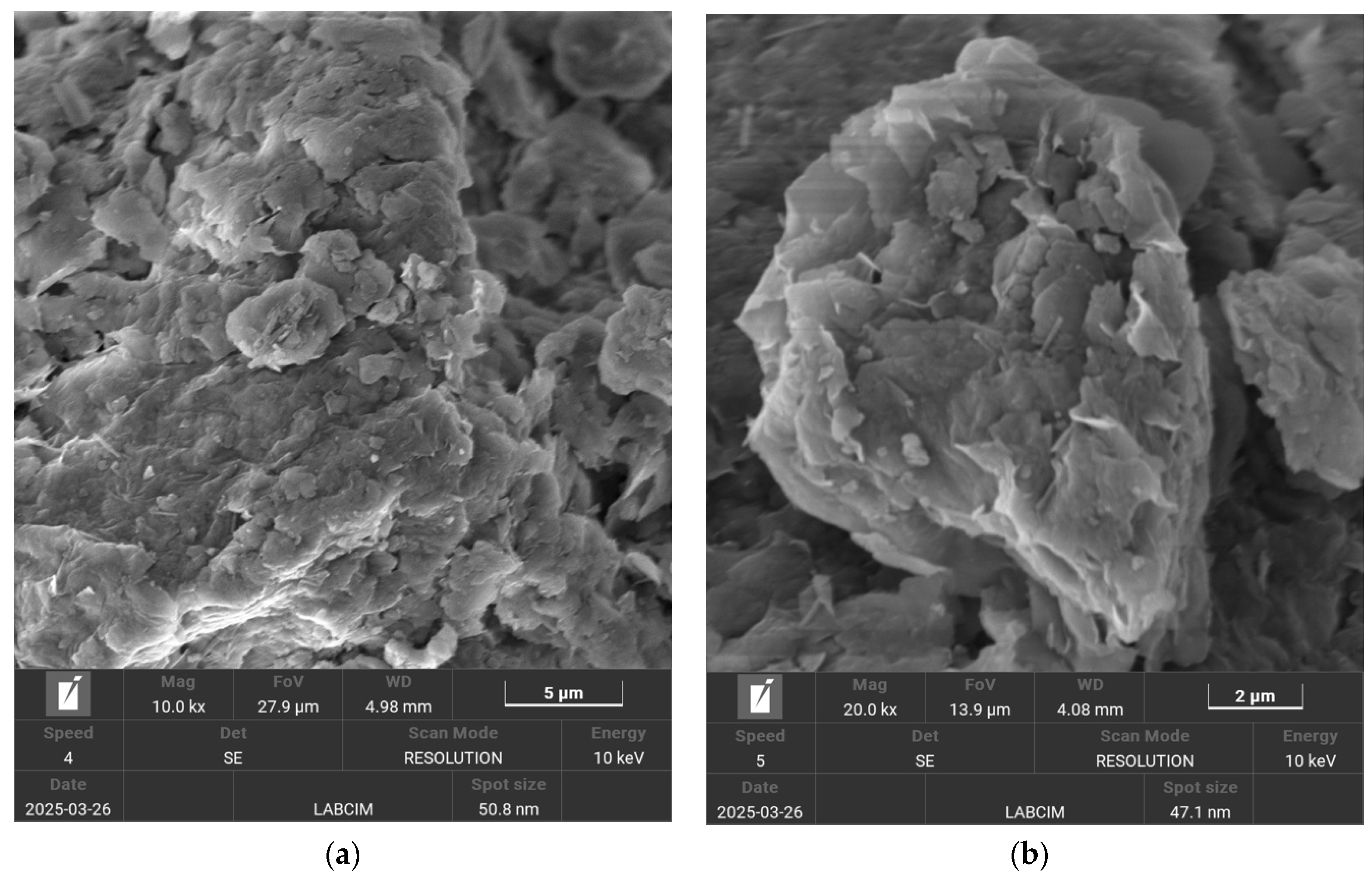
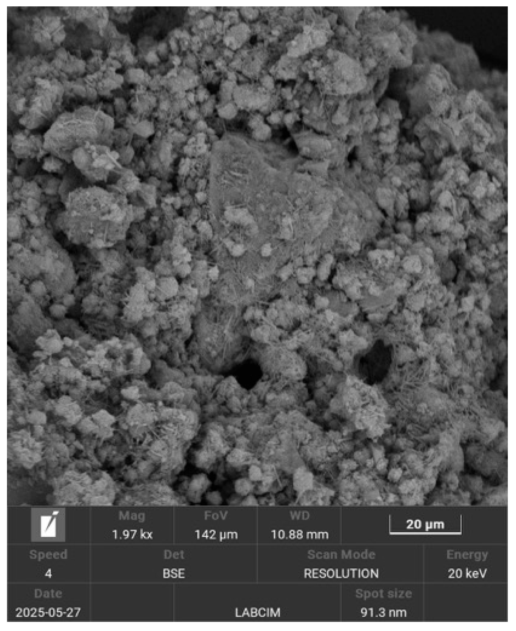
3.1.3. Scanning Electron Microscopy (SEM)
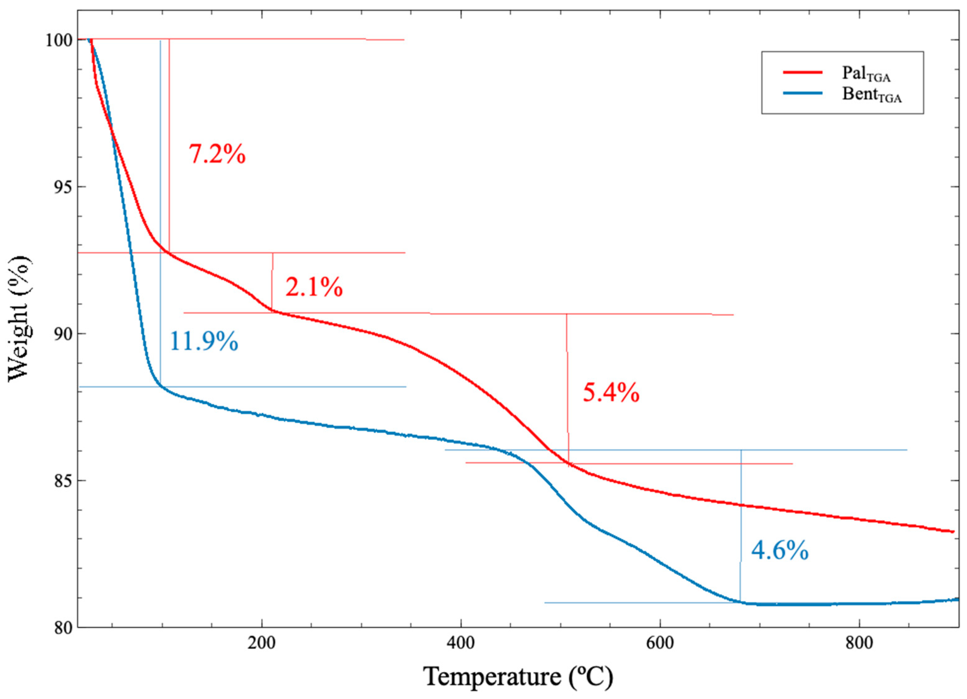
3.1.4. Thermogravimetry (TG)
3.1.5. Nitrogen Adsorption at 77 K
3.2. Technological Tests for Evaluating Extenders for Cement Slurries
3.2.1. Atmospheric Consistency
3.2.2. Free Water
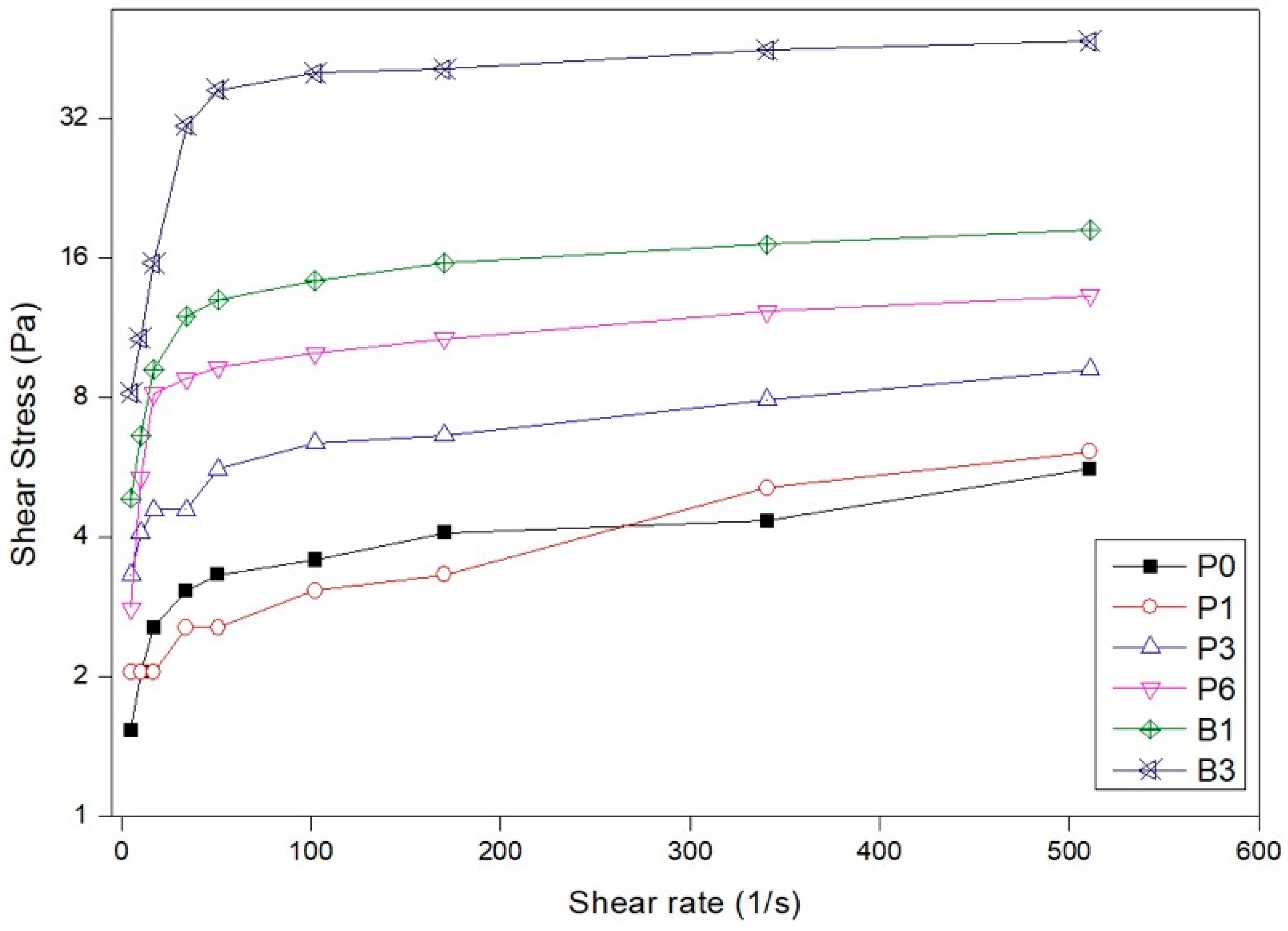
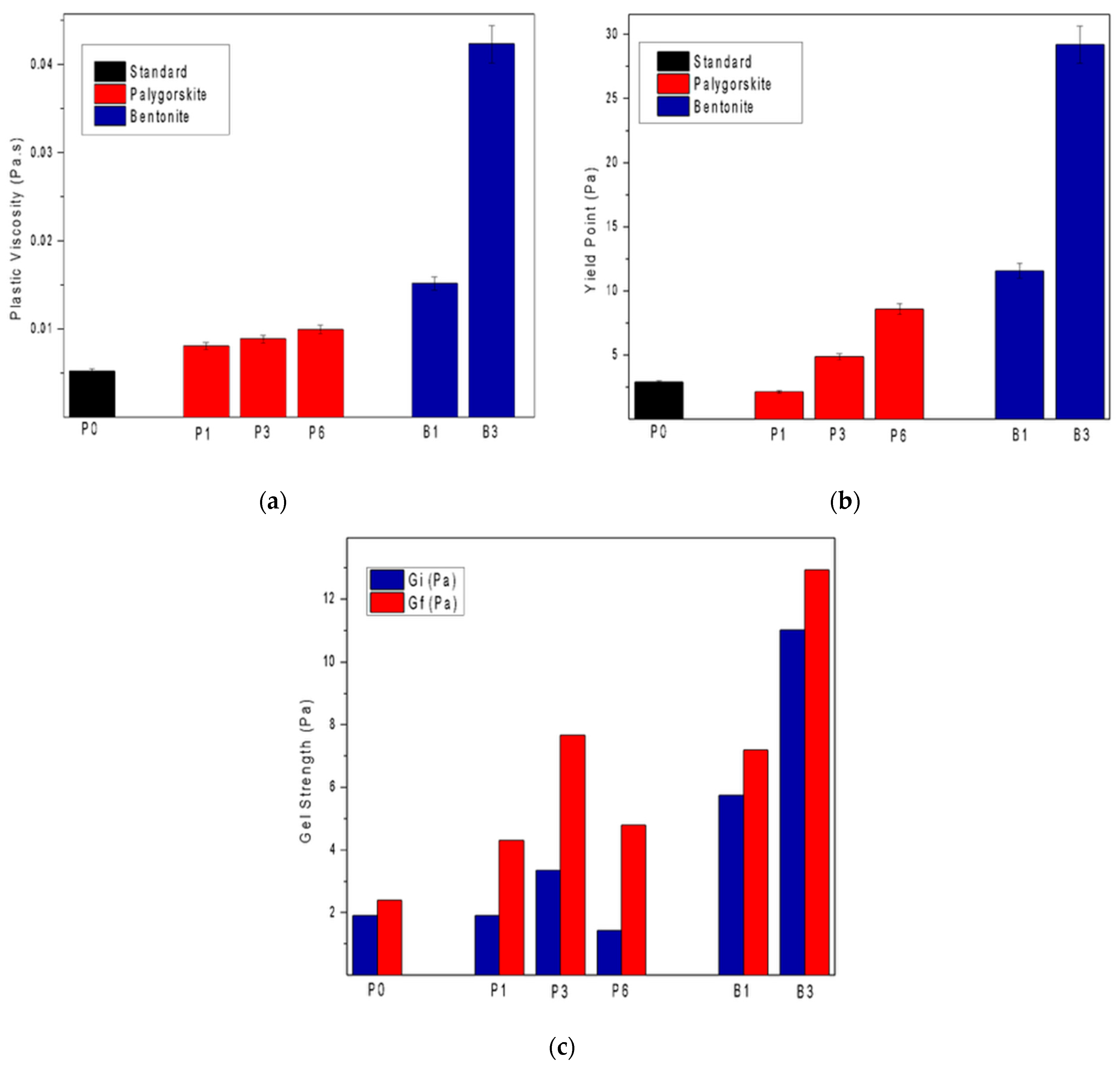
3.2.3. Rheology
3.2.4. Stability Test
3.2.5. Compressive Strength
3.3. Microstructural Analysis of Hardened Cement Paste Containing Palygorskite and Bentonite
4. Conclusions
- Palygorskite has proven to be a very versatile clay. As it is a 2:1 phyllosilicate, its specific area is large, providing essential industry applications. The nitrogen adsorption analysis allowed for the calculation of the specific area, which resulted in 142 m2/g, which is a high specific area value, and is one of its significant advantages.
- As it does not have exchangeable cations in its interlayers, after treatments, no changes were observed in the diffractogram patterns obtained for the palygorskite, with only slight increases in intensity in some peaks.
- The addition of palygorskite in light cement pastes influenced the rheological behavior, presenting lower viscosities when compared with pastes added with bentonite;
- The results obtained from the rheological parameters of the bentonite slurries were superior, given their more significant swelling capacity after hydration.
- The pastes with 6% palygorskite and 3% bentonite were those that presented superior stability, showing no sedimentation and providing better applicability in cementing operations.
- Additionally, the rheological behavior of the palygorskite-based slurries demonstrated a relevant operational advantage. The lower viscosity resulting from its fibrous morphology improved the pumpability and displacement efficiency, reducing the risk of high frictional pressures during cementing operations. At the same time, the physical entanglement of fibers ensured a sufficient yield strength and gel strength to maintain particle suspension, achieving a balance between flowability and stability.
- The paste with 1% palygorskite presented a superior result to the pastes with the addition of bentonite when their compressive strengths were evaluated.
- The microstructural evaluation confirmed that palygorskite, due to its fibrous morphology, promoted the formation of a more interconnected and homogeneous cement matrix. This characteristic contributed significantly to enhancing the mechanical integrity of the hardened cement paste. These findings position palygorskite as a technically viable alternative to traditional extenders, with additional microstructural benefits that extend beyond a simple density reduction.
Author Contributions
Funding
Data Availability Statement
Conflicts of Interest
References
- Murray, H.H. Traditional and New Applications for Kaolin, Smectite, and Palygorskite: A General Overview. Appl. Clay Sci. 2000, 17, 207–221. [Google Scholar] [CrossRef]
- Sun, X.; Chen, Y.; Liang, L.; Xie, G.; Peng, Y. Research on Hydrocyclone Separation of Palygorskite Clay. Minerals 2023, 13, 1264. [Google Scholar] [CrossRef]
- Pan, M.; Su, J.; Tang, L.; Hu, Z.; Huang, X. Insights into Phosphate Adsorption Performance onto Magnetic Thermal Modified Palygorskite Nanocomposites. Minerals 2023, 13, 293. [Google Scholar] [CrossRef]
- Baltar, C.A.M.; da Luz, A.B.; Baltar, L.M.; de Oliveira, C.H.; Bezerra, F.J. Influence of Morphology and Surface Charge on the Suitability of Palygorskite as Drilling Fluid. Appl. Clay Sci. 2009, 42, 597–600. [Google Scholar] [CrossRef]
- Murthy, R.V.V.R.; Mohammad, F.; Chavali, M. Development of Innovative Lightweight Slurry in Oil Well-Cementing Operations. Upstream Oil Gas Technol. 2021, 7, 100045. [Google Scholar] [CrossRef]
- Adjei, S.; Elkatatny, S. Overview of the Lightweight Oil-Well Cement Mechanical Properties for Shallow Wells. J. Pet. Sci. Eng. 2021, 198, 108201. [Google Scholar] [CrossRef]
- Santanna, V.C.; Araújo, G.C.N.; da Silva MT, A.; de Castro Dantas, T.N.; Pimentel, P.M. Water-Based Drilling Fluid with Palygorskite: Cutting Carrying and Contaminants. Clay Miner. 2023, 58, 95–101. [Google Scholar] [CrossRef]
- Zhuang, G.; Zhang, J.; Chen, J.; Liu, Q.; Fan, W.; Li, Q. Application of Nanofibrous Clay Minerals in Water-Based Drilling Fluids: Principles, Methods, and Challenges. Minerals 2024, 14, 842. [Google Scholar] [CrossRef]
- Magzoub, M.I.; Shamlooh, M.; Salehi, S.; Hussein, I.; Nasser, M.S. Gelation Kinetics of PAM/PEI Based Drilling Mud for Lost Circulation Applications. J. Pet. Sci. Eng. 2021, 200, 108383. [Google Scholar] [CrossRef]
- Thommes, M.; Kaneko, K.; Neimark, A.V.; Olivier, J.P.; Rodriguez-Reinoso, F.; Rouquerol, J.; Sing, K.S.W. Physisorption of Gases, with Special Reference to the Evaluation of Surface Area and Pore Size Distribution (IUPAC Technical Report). Pure Appl. Chem. 2015, 87, 1051–1069. [Google Scholar] [CrossRef]
- API. API SPEC 10A—Cements and Materials for Well Cementing|GlobalSpec. Available online: https://standards.globalspec.com/std/14208303/api-spec-10a (accessed on 11 January 2025).
- Liu, Y.; Wang, W.; Wang, A. Effect of Dry Grinding on the Microstructure of Palygorskite and Adsorption Efficiency for Methylene Blue. Powder Technol. 2012, 225, 124–129. [Google Scholar] [CrossRef]
- Zhang, T.; Huang, X.; Qiao, J.; Liu, Y.; Zhang, J.; Wang, Y. Recent Developments in Synthesis of Attapulgite Composite Materials for Refractory Organic Wastewater Treatment: A Review. RSC Adv. 2024, 14, 16300–16317. [Google Scholar] [CrossRef] [PubMed]
- Frost, R.L.; Xi, Y.; He, H. Synthesis, Characterization of Palygorskite Supported Zero-Valent Iron and Its Application for Methylene Blue Adsorption. J. Colloid Interface Sci. 2010, 341, 153–161. [Google Scholar] [CrossRef]
- Moore, D.M.; Reynolds, R.C. X-Ray Diffraction and the Identification and Analysis of Clay Minerals, 2nd ed.; Oxford University Press: New York, NY, USA, 1997. [Google Scholar]
- Xavier, K.C.M.; Filho, E.C.S.; Santos, M.S.F.; Santos, M.R.M.C.; Luz, A.B. Mineralogical, Morphological, and Surface Characterization of Attapulgite from Guadalupe-PI. Holos 2012, 5, 60–70. [Google Scholar] [CrossRef]
- Liu, H.; Xie, B.; Qin, Y. Effect of Bentonite on the Pelleting Properties of Iron Concentrate. J. Chem. 2017, 2017, 7639326. [Google Scholar] [CrossRef]
- Tsakiri, D.; Douni, I.; Taxiarchou, M. Structural and Surface Modification of Oxalic-Acid-Activated Bentonites in Various Acid Concentrations for Bleaching Earth Synthesis—A Comparative Study. Minerals 2022, 12, 764. [Google Scholar] [CrossRef]
- Christidis, G.E. Industrial Clays. In Handbook of Clay Science, 2nd ed.; Bergaya, F., Lagaly, G., Eds.; Elsevier: Amsterdam, The Netherlands, 2013; Volume 5, pp. 213–236. [Google Scholar]
- Önal, M.; Sarıkaya, Y. Some Physicochemical Properties of a Clay Containing Smectite and Palygorskite. Appl. Clay Sci. 2009, 44, 161–165. [Google Scholar] [CrossRef]
- Wang, S.; Liu, X.; Zhang, C.; Hu, W.; Liu, Y.; Fu, X.; Jun, Y.; Wei, S. Adsorption and Selective Mechanism of Pb2+ and Cd2+ on the Surface of Calcined Modified Attapulgite. Sep. Purif. Technol. 2025, 353, 128377. [Google Scholar] [CrossRef]
- Sakizci, M.; Erdoğan Alver, B.; Yörükoğullari, E. Thermal Behavior and Immersion Heats of Selected Clays from Turkey. J. Therm. Anal. Calorim. 2009, 98, 429–436. [Google Scholar] [CrossRef]
- Madejová, J.; Komadel, P. Baseline Studies of the Clay Minerals Society Source Clays: Infrared Methods. Clays Clay Miner. 2001, 49, 410–432. [Google Scholar] [CrossRef]
- Zhang, J.; Wang, Q.; Chen, H.; Wang, A. XRF and Nitrogen Adsorption Studies of Acid-Activated Palygorskite. Clay Miner. 2010, 45, 145–156. [Google Scholar] [CrossRef]
- Chang, Y.; Liu, H.; Zha, F.; Chen, H.; Ren, X.; Lei, Z. Adsorption of Pb(II) by N-Methylimidazole Modified Palygorskite. Chem. Eng. J. 2011, 167, 183–189. [Google Scholar] [CrossRef]
- Adjei, S.; Elkatatny, S.; Sarmah, P.; Abdelfattah, A.M. Evaluation of Calcined Saudi Calcium Bentonite as Cement Replacement in Low-Density Oil-Well Cement System. J. Pet. Sci. Eng. 2021, 205, 108901. [Google Scholar] [CrossRef]
- Nascimento, R.C.A.M.; Amorim, L.V.; Santana, L.N.L. Development of aqueous fluids with bentonite clay for drilling of onshore oil wells. Cerâmica 2010, 56, 179–187. [Google Scholar] [CrossRef]
- Li, P.; Hu, M.; Liu, M.; Zhang, H.; Zhao, J.; Xia, X.; Guo, J. Regulation of Oil Well Cement Paste Properties by Nanoclay: Rheology, Suspension Stability and Hydration Process. Constr. Build. Mater. 2023, 377, 131049. [Google Scholar] [CrossRef]
- Silva, F.P.F.; Marques, J.F.S.; Vieira, M.M.; Melo, M.A.F.; Freitas, J.C.O.; Santos, P.H.S.; Dantas, T. OTIMIZAÇÃO DE FORMULAÇÃO DE PASTAS DE CIMENTO CONTENDO BENTONITA PARA APLICAÇÃO EM POÇOS PETROLÍFEROS COM BAIXO GRADIENTE DE FRATURA. In Proceedings of the 8º Congresso Brasileiro de Pesquisa e Desenvolvimento em Petróleo e Gás, Curitiba, Brazil, 20–22 October 2015. [Google Scholar]
- Fode, T.A.; Jande, Y.A.C.; Kivevele, T. Effects of Raw and Different Calcined Bentonite on Durability and Mechanical Properties of Cement Composite Material. Case Stud. Constr. Mater. 2024, 20, e03012. [Google Scholar] [CrossRef]
- Li, Z.; Tang, L.; Zheng, Y.; Tian, D.; Su, M.; Zhang, F.; Ma, S.; Hu, S. Characterizing the Mechanisms of Lead Immobilization via Bioapatite and Various Clay Minerals. ACS Earth Space Chem. 2017, 1, 152–157. [Google Scholar] [CrossRef]


| Slurry | Water (g) | Cement Class G (g) | Bentonite (g) | Palygorskite (g) |
|---|---|---|---|---|
| P0 | 440.76 | 493.87 | - | - |
| B1 | 439.98 | 489.74 | 4.90 | - |
| B3 | 438.46 | 481.71 | 14.45 | - |
| B6 | 436.28 | 470.13 | 28.21 | - |
| P1 | 439.79 | 489.93 | - | 4.90 |
| P3 | 438.83 | 486.07 | - | 14.47 |
| P6 | 436.99 | 469.46 | - | 28.17 |
| Oxide | % Weight | |
|---|---|---|
| Palygorskite | Bentonite | |
| MgO | 5.35 | 3.81 |
| Al2O3 | 18.36 | 23.85 |
| SiO2 | 59.78 | 56.62 |
| K2O | 3.69 | 0.55 |
| CaO | 0.58 | 1.26 |
| TIO2 | 1.08 | 0.63 |
| Fe2O3 | 11.16 | 13.28 |
| Material | SBET (m2/g) | Constante C | VTP (cm3/g) | Vmeso(cm3/g) |
|---|---|---|---|---|
| Palygorskite | 142.59 | 218.28 | 32.75 | 29.25 |
| Bentonite | 47.05 | 344.12 | 0.08 | 0.073 |
| Standard | P1 | P3 | P6 | B1 | B3 |
|---|---|---|---|---|---|
| 18.62% | 16.69% | 12.61% | 4.25% | 5.08% | 2.10% |
Disclaimer/Publisher’s Note: The statements, opinions and data contained in all publications are solely those of the individual author(s) and contributor(s) and not of MDPI and/or the editor(s). MDPI and/or the editor(s) disclaim responsibility for any injury to people or property resulting from any ideas, methods, instructions or products referred to in the content. |
© 2025 by the authors. Licensee MDPI, Basel, Switzerland. This article is an open access article distributed under the terms and conditions of the Creative Commons Attribution (CC BY) license (https://creativecommons.org/licenses/by/4.0/).
Share and Cite
Ventura, R.A.; Carvalho, J.V.A.; da Silva, R.R.; Pinto, F.G.H.S.; Freitas, J.C.O.; Pergher, S.B.C. Palygorskite as an Extender Agent in Light Cement Pastes for Oil Wells: Performance Analysis. Minerals 2025, 15, 637. https://doi.org/10.3390/min15060637
Ventura RA, Carvalho JVA, da Silva RR, Pinto FGHS, Freitas JCO, Pergher SBC. Palygorskite as an Extender Agent in Light Cement Pastes for Oil Wells: Performance Analysis. Minerals. 2025; 15(6):637. https://doi.org/10.3390/min15060637
Chicago/Turabian StyleVentura, Rafael A., José V. A. Carvalho, Raphael R. da Silva, Francisco G. H. S. Pinto, Júlio C. O. Freitas, and Sibele B. C. Pergher. 2025. "Palygorskite as an Extender Agent in Light Cement Pastes for Oil Wells: Performance Analysis" Minerals 15, no. 6: 637. https://doi.org/10.3390/min15060637
APA StyleVentura, R. A., Carvalho, J. V. A., da Silva, R. R., Pinto, F. G. H. S., Freitas, J. C. O., & Pergher, S. B. C. (2025). Palygorskite as an Extender Agent in Light Cement Pastes for Oil Wells: Performance Analysis. Minerals, 15(6), 637. https://doi.org/10.3390/min15060637