Article

Lacustrine Gravity-Flow Deposits and Their Impact on Shale Pore Structure in Freshwater Lake Basins: A Case Study of Jurassic Dongyuemiao Member, Sichuan Basin, SW China

1
School of Geosciences and Technology, Southwest Petroleum University, Chengdu 610500, China
2
Collaborative Innovation Center of Shale Gas Resources and Environment, Chengdu 610500, China
3
Sinopec Exploration Company, Chengdu 610041, China
*
Author to whom correspondence should be addressed.
Minerals 2025, 15(5), 473; https://doi.org/10.3390/min15050473
Submission received: 3 March 2025 / Revised: 26 April 2025 / Accepted: 27 April 2025 / Published: 30 April 2025
(This article belongs to the Special Issue Element Enrichment and Gas Accumulation in Black Rock Series)

Abstract

:
In recent years, the successful application of gravity-flow deposit theory in major petroliferous basins in China had attracted extensive attention in the field of sedimentology and had become a key research frontier. This study utilized core, drilling, logging, and microphotograph data, along with low-temperature nitrogen adsorption and high-pressure mercury injection experiments. It discussed the characteristics of gravity-flow deposits, sedimentary microfacies, sedimentary models, and the significance of gravity-flow deposits to pore heterogeneity in shale reservoirs, focusing on the first submember of the Dongyuemiao Member (referred to as the Dong 1 Member) in the Fuling area of the Sichuan Basin. The results indicated the development of four types of mudrock in the Dong 1 Member: massive to planar laminated shell mudrock (F1), planar laminated bioclastic mudrock (F2), planar laminated silty mudrock (F3), and massive mudrock (F4). These corresponded to debris flow deposits (F1, F2), turbidite deposits (F3), and suspension deposits (F4). According to the characteristics of lithofacies combinations and sedimentary features, four sedimentary microfacies were identified: gravity-flow channel, tongue-shaped, lobate, and semi-deep lake mud. The Shell Banks were disturbed by earthquakes, tides, storms, and other activities. Silt, clay, fossil fragments, plant debris, and other materials were deposited under the influence of gravity, mixing with surrounding water to form an unbalanced and unstable fluid. When pore pressure exceeded viscous resistance, the mixed fluid became unbalanced, and gravity flow began to migrate from the slope to the center of the lake basin. A sedimentary unit of gravity-flow channel-tongue-shaped-lobate was developed in the Fuling area. The Fuling area’s gravity-flow depositional system resulted in distinct microfacies within the Dongyuemiao Member, each exhibiting characteristic lithofacies associations. Notably, lobate deposits preferentially developed lithofacies F3, which is distinguished by significantly higher clay mineral content (60.8–69.1 wt%) and elevated TOC levels (1.53–2.45 wt%). These reservoir properties demonstrate statistically significant positive correlations, with clay mineral content strongly influencing total pore volume and TOC content specifically enhancing mesopore development (2–50 nm pores). Consequently, the F3 lithofacies within lobe deposits emerges as the most prospective shale gas reservoir unit in the study area, combining optimal geochemical characteristics with favorable pore-structure attributes.

1. Introduction

The gravity-flow deposit theory was first proposed in the 1950s to explain large-scale terrestrial clastic sediments in deep-water environments. Outcrop section observations, flume simulation experiments, and drill core observations were used to conduct extensive studies on gravity-flow types, migration mechanisms, sedimentary characteristics, and sedimentary models, which greatly enriched the gravity-flow deposit theory [1,2,3,4,5,6]. Subaqueous gravity flow was an important migration pattern that migrates shallow sediments into deep water and was widely developed in lacustrine environments [7,8]. In recent years, multiple studies on gravity-flow deposits in marine sediments were published, and the theory was applied to illustrate gravity flow in lacustrine environments, providing valuable insights. Examples include the following: lake regression-type gravity-flow deposits in the Chang 7 Member in the Ningxian area of the Ordos Basin [1]; lake transgression-type gravity-flow deposits in the upper submember of the Sha4 Member in the Shengtuo area of the Dongying depression [9]; gravity-flow deposits in the Jurassic Sangonghe Formation in the western Jungger Basin [10]; and lake flooding-type gravity-flow deposits in the Qingshankou Formation and the Nenjiang Formation in the Songliao Basin, among others [11]. Unlike marine turbidites, which often exhibit complete Bouma sequences due to sustained flow regimes [12], lacustrine gravity flows are typically characterized by truncated sequences (Tc–Te) and higher clay content, reflecting shorter transport distances and rapid sediment fallout in confined basins [13].
Since the Indosinian movement, the Sichuan Basin had evolved from a foreland basin to a depression basin in the Early Triassic. An organic-rich black mudrock containing thick shell laminae and silt laminae developed in the Dongyuemiao Member of the Ziliujing Formation. It was deposited in shallow lakes and semi-deep lakes. The Dongyuemiao Member shale was characterized by high TOC content and extensive development in the basin. It had become a key target for lacustrine shale oil and gas exploration in the Sichuan Basin [14,15]. Regarding the genesis of fine-grained sediments deposited in deep-water environments, previous studies have shown that they were deposited in suspension. However, recent studies have shown that fine-grained sediments, such as silty and muddy sediments, could be migrated and deposited via gravity flow [11,16]. In addition, gravity-flow deposits were frequently found in the Daanzhai Member and the Dongyuemiao Member shale [17,18,19]. However, the genetic mechanisms and sedimentary models of lacustrine gravity flow remained unclear, which restricted the exploration and development of lacustrine shale oil and gas in the Dongyuemiao Member.
This study was based on core, drilling, logging, and microphotograph data. The entire core of the Dong 1 submember was described in detail, and the sedimentary characteristics and microfacies of lacustrine fine-grained gravity-flow deposits in the study area were analyzed. Based on the sedimentary background and the characteristics of gravity-flow deposits, the developmental characteristics of gravity-flow deposits in the Dong 1 submember were analyzed, and a sedimentary model of lacustrine gravity flow was established. By combining low-temperature nitrogen adsorption and high-pressure mercury injection experiments, the influence of gravity-flow deposit types on shale reservoirs in the study area was discussed. The conclusions drawn from this study provided a reference for the exploration and development of lacustrine shale gas and the prediction of the reservoir.

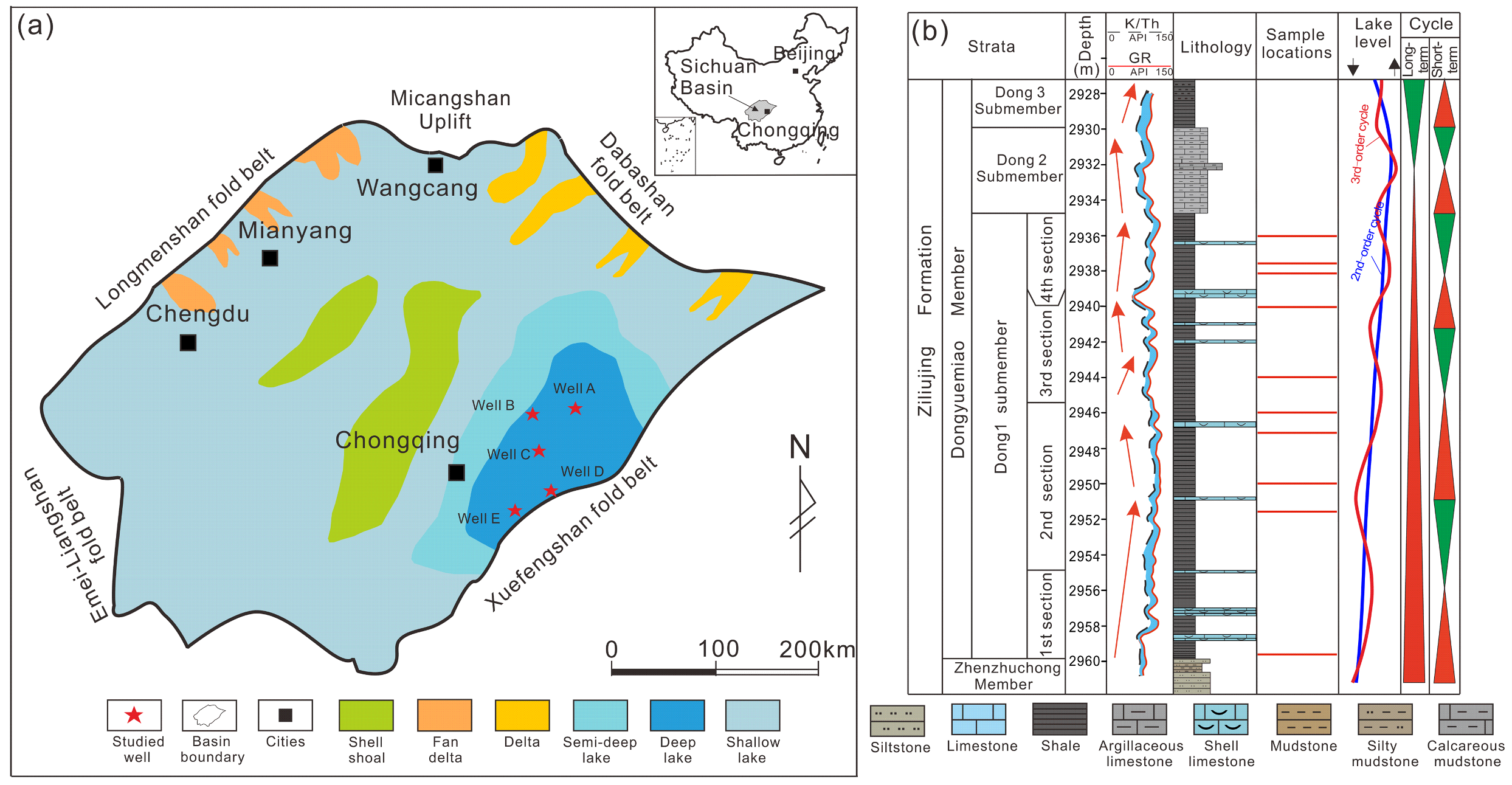
2. Geological Setting

The Fuling area was located in the eastern Sichuan Basin and is influenced by Indosinian and Himalayan movements. As a result, a series of large-scale anticlinoria and synclinoria with NE–SW extensions developed (Figure 1a). During the Indosinian movement, basin subsidence created depression settings, while subsequent Yanshan Movement compression from the Daba and Xuefeng Mountain Fold Belts generated high-angle slopes (5–15°) through asymmetric subsidence (rapid footwall uplift and hanging wall collapse). The basin’s active syn-depositional faults could generate earthquakes, and seismic triggers remain speculative due to soft-sediment deformation structures in the core (as discussed in Section 4.1.2) [20]. Abundant quartz and feldspar grains (16%–63.8%, in XRD) and plant debris in marginal facies confirm fluvial input from the northern paleo-river system. This aligns with regional studies documenting Late Jurassic drainage networks [21]. Due to three large-scale lake transgression events, the Dongyuemiao Member, Daanzhai Member, and Lianggaoshan Formation developed three sets of Jurassic organic-rich shales [22,23]. The Dongyuemiao Member in the Fuling area was primarily deposited in a shallow to semi-deep lake sedimentary environment. According to the lithologic characteristics and lithological combinations, it could be divided into three submembers from bottom to top: Dong 1 submember, Dong 2 submember, and Dong 3 submember (Figure 1b). The Dong 1 submember could be further subdivided into four layers [21]. During the Dong 1 submember depositional period, lake transgression occurred continuously, and black shale, gray mudstone, and shell limestone were deposited in this environment. Laminae (<1 cm) and interlayers (>10 cm) frequently developed in black shale, which were primarily deposited in a semi-deep-lake sedimentary environment, where gravity-flow deposits were observed. In the Dong 2 submember depositional period, lake regression began, the sedimentary facies transitioned to a shallow lake facies, and gray muddy limestone, mudstone, and silty mudstone developed. In the Dong 3 submember depositional period, lake regression entered its late stage, the sedimentary facies shifted to a shallow lake facies, and the lithology was primarily gray mudstone.

3. Samples and Methods

3.1. Samples

The testing samples used in this study were from Well A (sample depth between 2640 and 2670 m), Well B (sample depth between 2493 and 2521 m), Well C (sample depth between 2933 and 2960 m), Well D (sample depth between 2737 and 2770 m), and Well E (sample depth between 2830 and 2857 m). The total testing sample number was 167, including 36 samples in 1st section, 46 samples in 2nd section, 44 samples in 3rd section and 41 samples in 4th section. Among these, Well A was the closest to the sedimentary provenance, while Well E was the farthest. The lithology of these samples was primarily gray–black and black shale, with silt, shale lamina, and interbeds also present. Thin-section and SEM analyses were conducted on all samples; additionally, 16 samples were utilized for high-pressure mercury injection and nitrogen adsorption experiments.

3.2. Methods

3.2.1. Thin-Section Analysis

A 0.03 mm-thick thin rock section was used for thin-section identification. All sections were identified using a polarizing microscope to study the clastic components, sedimentary structures, and shale lamina development.

3.2.2. TOC and X-Ray Analysis

All samples comprising all lithofacies of the Dongyuemiao Member were collected for total organic carbon (TOC) and X-ray diffraction (XRD) analysis. Before TOC analysis, rock samples were first crushed to a powder (~200 mg) and treated with hydrochloric acid (10% by volume) at 60 °C to remove carbonate minerals. Powdered samples were then washed with distilled water to remove residual hydrochloric acid and dried overnight. Finally, a TOC measurement was conducted using a LECO CS-200 analyzer (LECO Corporation, St. Joseph, MI, USA). And a XRD measurement was conducted using the D8A25 diffractometer from Germany Bruce Company (D8A25 diffractometer, Hong Kong, China).

3.2.3. Scanning Electron Microscopy (SEM) Analysis

A cube sample with a 1 cm side length was used to prepare the experimental sample for the scanning electron microscope. First, the sample surface was polished with sandpaper. Next, it was polished using argon ions, and the polished surface was coated with gold. Subsequently, the FEI Quanta 450 FEG (GFE-SEM, FEI, Hillsboro, OR, USA) scanning electron microscope was employed to observe the sample’s pore types, pore sizes, morphology, mineral composition, and organic matter development. The acceleration voltage of the scanning electron microscope was 20 kV, and the maximum resolution was 10 nm.

3.2.4. Low-Temperature N2 Adsorption (LTNA)

The nitrogen adsorption experiment was conducted using a powder sample with a particle size of 40 to 80 mesh (the pore size is between 180 and 425 μm). The powder sample was dried at 120 °C for 24 h. After the residual gas was removed, the experiment was conducted using the Quantachrome Autosorb-1 nitrogen adsorption instrument (Autosorb-1 nitrogen adsorption instrument, Micromeritics, Shanghai, China). The pore size distribution of the tested sample was calculated using the Brunauer–Emmett–Teller (BET) model and the Barrett–Joyner–Halenda (BJH) model.

3.2.5. Mercury Intrusion Porosimetry (MIP)

A cubic sample with a 1 cm side length was used to conduct a high-pressure mercury intrusion experiment and was tested using an AutoPore IV 9500 automatic mercury intrusion meter (AutoPore IV 9500 automatic mercury intrusion, Micromeritics, Shanghai, China). The maximum mercury injection pressure was 200 MPa. The pore size was calculated using the Washburn (1921) formula [21]. The experimentally measurable pore size range was 6 nm to 361 μm.

4. Results and Discussion

4.1. Lithofacies Types and Characteristics

As the most intuitive data for analyzing sedimentary facies and the sedimentary environment, drilling cores could be used to accurately identify shale lithofacies. The identification results were of great significance for analyzing the sedimentary environment and inferring sedimentary processes. Based on the characteristics of silt and shell laminae developed in shale in the study area, and following the lithofacies classification scheme proposed by Liu (2017) and Lazar (2015) [22,24], a ‘lamina pattern + mineral composition’ shale lithofacies division scheme was developed. Based on macroscopic observations, as well as those from optical and scanning electron microscopes (SEM), the characteristics of bedding types and sedimentary structures were identified. This analysis resulted in the division of four types of shale lithofacies in the Dong 1 submember: massive to planar laminated shell mudrock (F1), planar laminated bioclastic mudrock (F2), planar laminated silty mudrock (F3), and massive mudrock (F4) (Table 1).
Integrated petrographic and mineralogical analyses including core observations, thin-section petrography, X-ray diffraction (XRD) whole-rock analysis, and field-emission scanning electron microscopy (FE-SEM) reveal that the Dongyuemiao Member shale is predominantly composed of quartz, dolomite, and clay minerals, with the clay fraction consisting of illite, kaolinite, chlorite, and illite-smectite mixed-layer (I/S) minerals (Table 2 and Table 3).

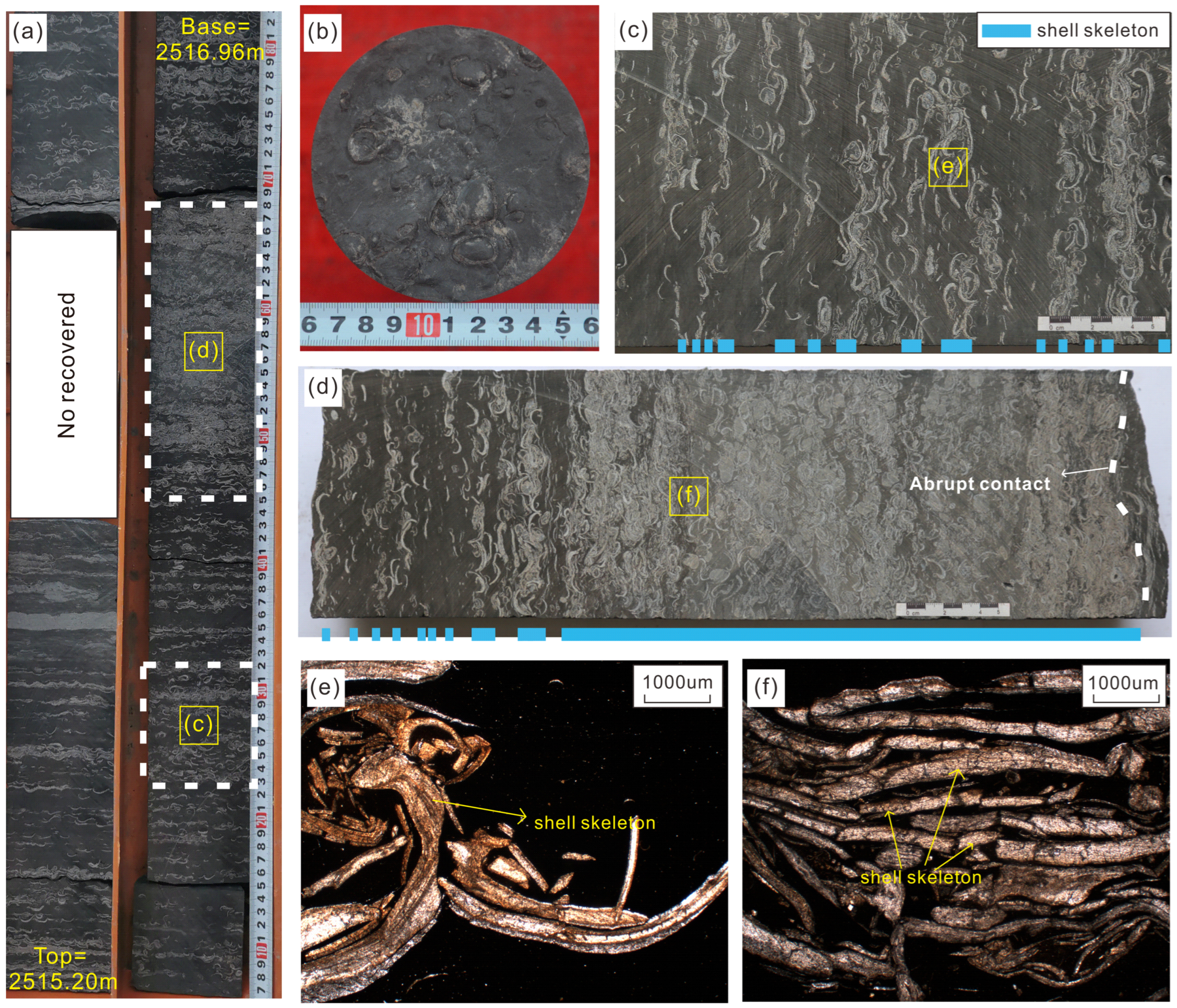
4.1.1. Lithofacies 1: Shell Skeletal-Bearing Mudrock

F1 consisted of a shell skeleton and shale matrix. The shell skeleton was mainly presented in two forms: gray–white thin-shell skeleton lamina and hydroplaning-modified shell beds (Figure 2a), which was most developed in the first and third layers of the Dong 1 submember. In general, the shell shape was well preserved, and the deposition was heterogeneous (Figure 2b). According to the core and thin-section observation results, the thin-shell skeleton lamina contained shells that were mainly distributed along the shale bedding. Most shell dimensions were between 4 mm and 10 mm. The shell laminae were mainly composed of single or multiple shell layers, and the thickness was between 1 mm and 15 mm (Figure 2c). The black shale matrix was filled between the single shells. In the hydroplaning-modified shell beds, shells were closely stacked and deposited heterogeneously. The thickness of the shell interlayer was about 90 mm (Figure 2d,f).
For the shell skeleton lamina and interlayer deposited in deep water, these layers might have been deposited by debris flow. Debris flow, as a viscous, non-Newtonian rheological fluid, exerted a significant erosive effect on the lacustrine basin. The shell skeleton made abrupt contact with the shale matrix [24,25,26,27,28]. The larger shell was deposited first in the flow, forming hydroplaning-modified shell beds (Figure 2d). As the fluid energy decreased, the smaller shell was deposited, forming a thin-shell skeleton lamina.

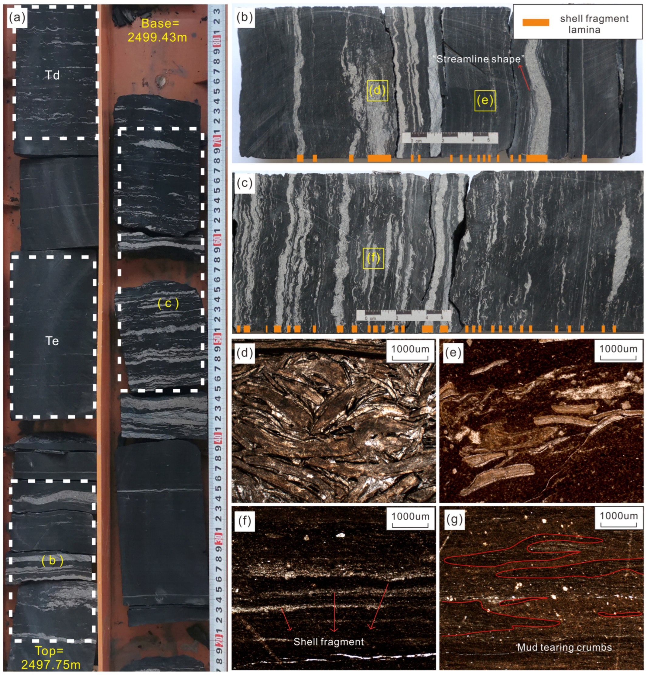
4.1.2. Lithofacies 2: Parallel-Laminate Bioclastic Mudrock

F2 consisted of bioclastic and shale matrix and was present in the form of lamina within F2 (Figure 3a). The parallel-laminate bioclastic mudrock in the Dong 1 submember of the Fuling area was primarily developed at the top of the second and third layers. Core and thin-section observations indicated that the gray–white shell fragment lamina developed with unequal thickness; the thickness ranged from 1 to 12 mm and exhibited various shapes, including irregular oblique shell stacking fabrics and streamlined shapes with smooth edges (Figure 3b,c). Previous studies suggested that, due to differences in density and viscosity of the carrier fluid, the deformation process occurred in unconsolidated shell fragment sediment during continuous migration, resulting in a variety of forms of shell fragment lamina.
Similar to the formation of shell skeleton laminae and interlayers, the shell fragment lamina was primarily deposited by debris flow. A previous study suggested that highly fragmented bioclastic sediment is an indicative feature of debris flow caused by paleostorms [12]. As a viscous and plastic rheological fluid, debris flow existed in an unbalanced state characterized by differences in internal shear stress [29]. Therefore, various morphologies of the shell fragment lamina developed in the planar laminated bioclastic mudrock of the Dong 1 submember in the Fuling area. If the inner shear stress of the debris flow was relatively small, the shell was less damaged, and clay minerals filled the spaces between the shell fragments. The size of the shell fragments ranged from 0.5 to 1.5 mm (Figure 3d). If the inner shear stress of the debris flow was relatively high, the shells sustained further damage and were deposited in a non-directional manner, with sizes ranging from 0.5 to 1.0 mm (Figure 3e). If the flow behaves like a dilute fluid, in distal segments, where fossil fragments are more broken, the shells were severely destroyed, and the shell fragments were deposited in layers (Figure 3f). In addition, due to the erosion of the debris flow along the lakebed, mud crumbs or muddy sediments with high viscosity were incorporated into the gravity-flow deposit system, forming a mud-crumb structure [29]. Under the influence of the internal shear stress of the debris flow, the mud crumbs were distributed in a torn manner (Figure 3g).

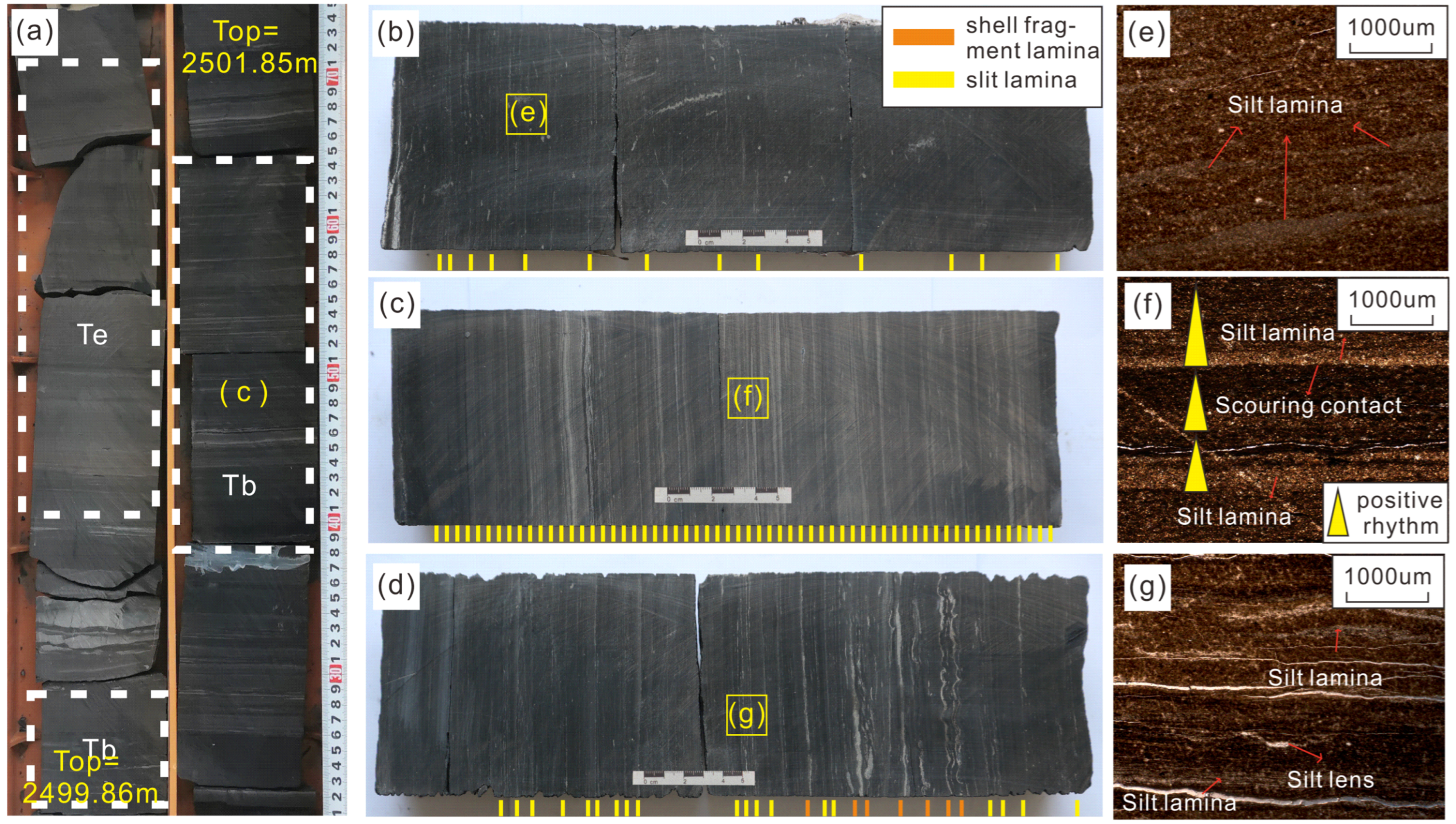
4.1.3. Lithofacies 3: Planar and Parallel-Laminated Silty Mudrock

F3 consisted of gray–white silt laminae and a shale matrix, developing in parallel along the bedding direction. The thickness of a single silt lamina ranged from about 0.8 to 2 mm (Figure 4a). Based on the frequency of silt lamina development, F3 could be divided into two layers: a low-frequency layer and a high-frequency layer. In the low-frequency layer, the thickness of the silt lamina was reduced, and the interval between laminae was wider, indicating an unequal thickness arrangement (Figure 4b). In contrast, the interval between laminae in the high-frequency layer was approximately 1 mm (Figure 4c). In the transitional zone between turbidity current and muddy debris flow deposition, both shell fragment laminae and silt laminae were observable from the bottom to the top (Figure 4d).
A previous study showed that the silt lamina deposited in deep water could migrate due to turbidity currents [17]. As a non-viscous, Newtonian rheological fluid, turbidity currents exhibited two characteristics during migration. First, as the flow velocity gradually decreased, suspended sediment began to settle due to gravity [30], forming unequally thick silt laminae and shale (Figure 4e) and exhibiting a positive rhythmic structure with finer grain sizes from bottom to top (Figure 4f). Second, as the migration distance increased, the internal energy of the turbidity current decreased, causing the bottom to migrate in laminar flow, generally in contact with the underlying mudstone [31] (Figure 4f). Additionally, similar to bottom current deposition, sandy lenticles could also be deposited via turbidity currents [9]. The difference between them was that the sedimentary architecture in sandy lenticles formed via bottom currents was primarily wavy bedding, while that formed via turbidity currents was primarily massive bedding (Figure 4g)

4.1.4. Lithofacies 4: Massive Mudrock

F4 consisted of gray–black shale, and bedding had developed in this formation (Figure 5a). Microscopic observations revealed that the shale is rich in organic matter, with clay minerals as the main rock-forming component, comprising about 60% of the total content. Additionally, quartz and carbonate minerals were also present (Figure 5c). Additionally, framboidal pyrite and carbonized plant debris were observed in the SEM results (Figure 5b,e). The genesis of massive mudrock was primarily attributed to gravity-flow intervals or in situ deposition of suspended matter from turbidity currents. The slow, suspended deposition of muddy sediment in a deep-lake sedimentary environment could also lead to the formation of massive mudrock. Although the macroscopic laminae of massive mudstone in the study area are not well developed, the nanoscale pyrite laminae can be seen under the scanning electron microscope (Figure 5d). F4 was deposited in a semi-deep to deep sedimentary environment.

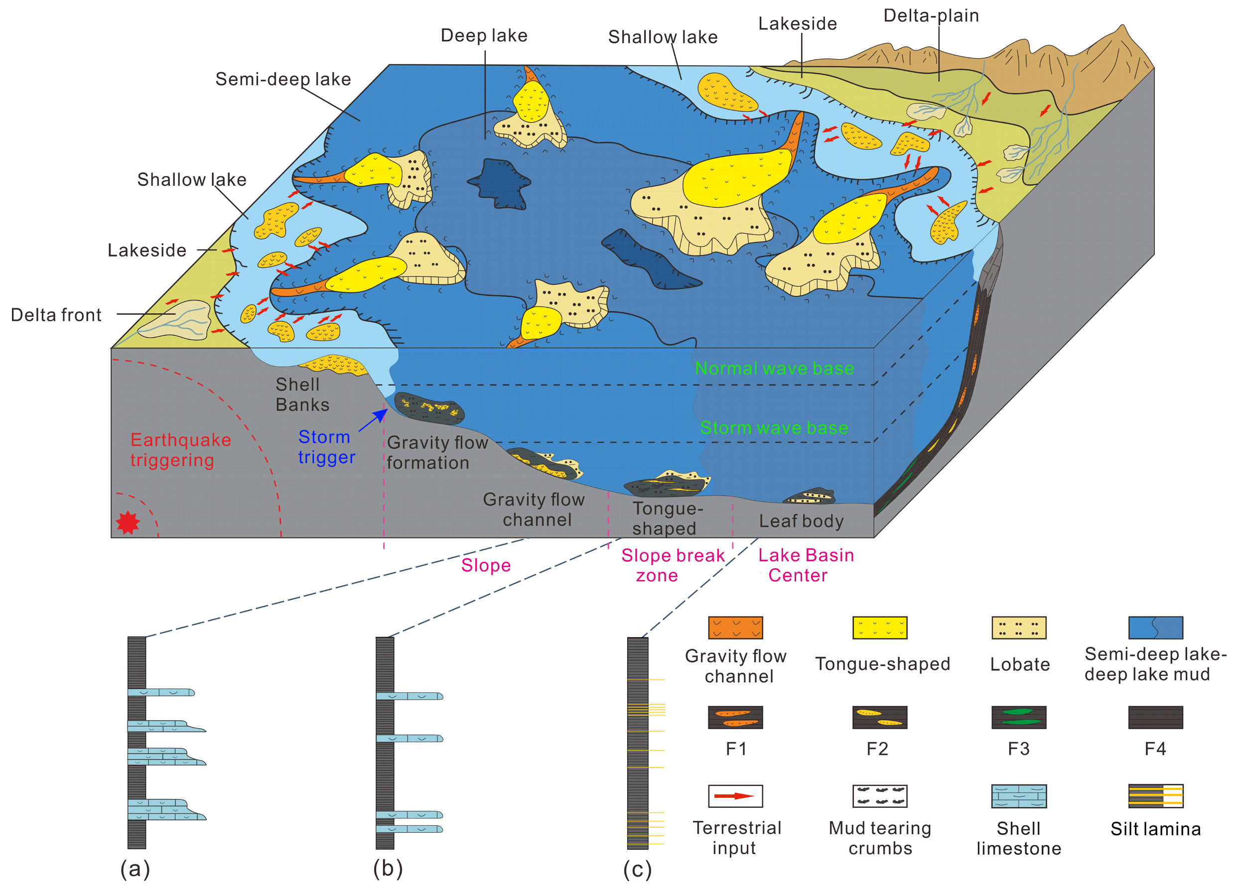
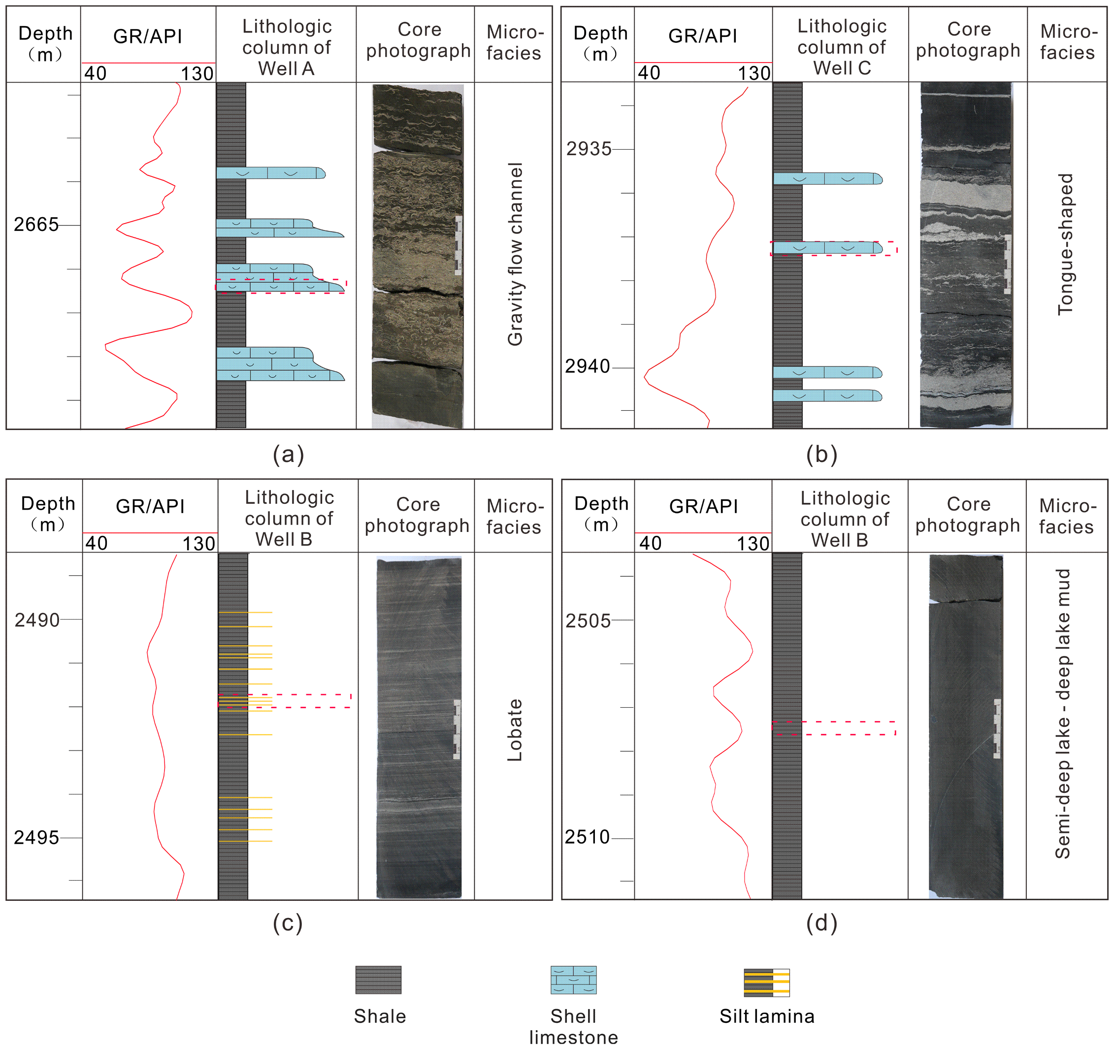
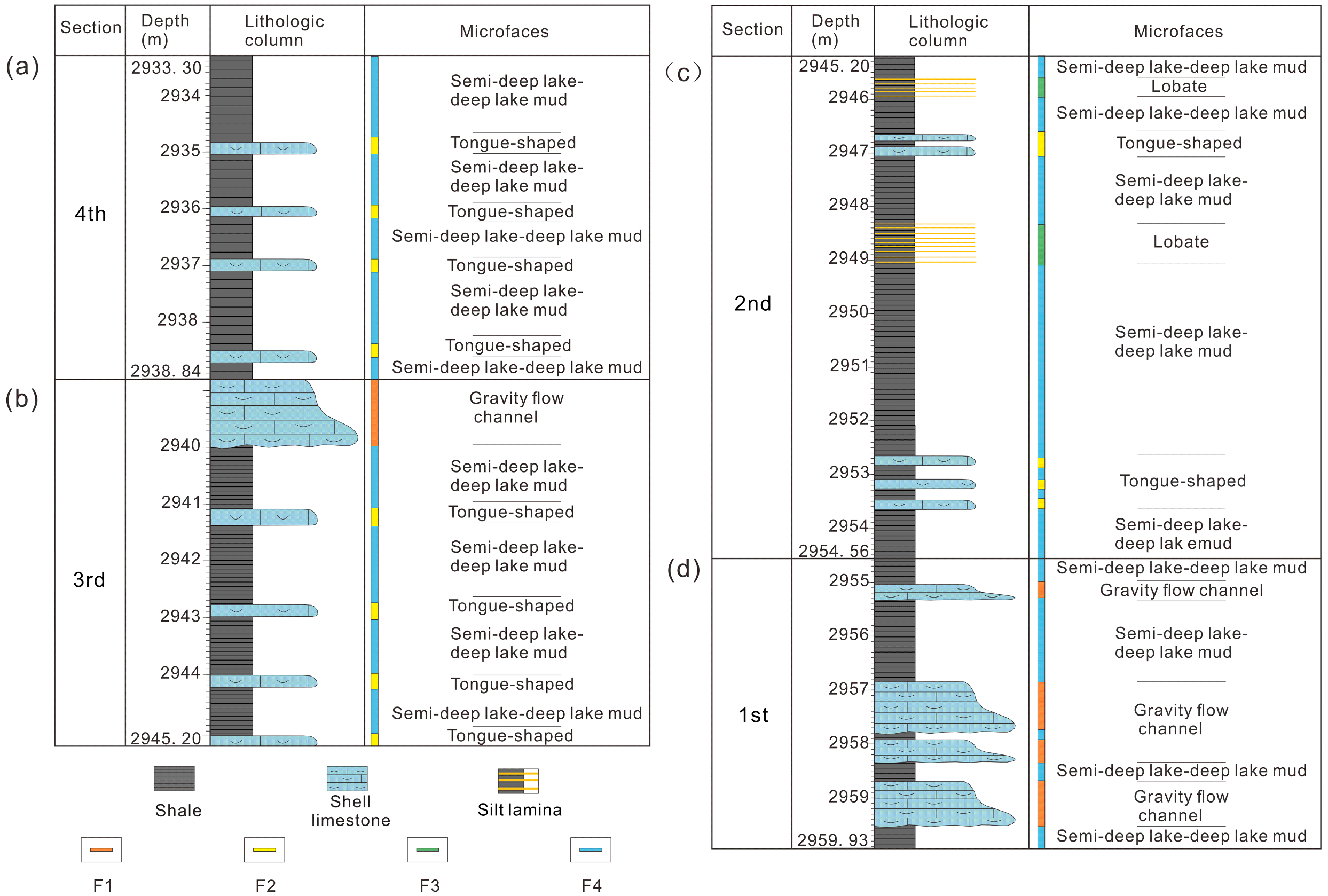
4.2. Division of Gravity-Flow Sedimentary Microfacies

Based on the differences in sedimentary characteristics and depositional positions of gravity flow, four types of sedimentary microfacies were identified in the Dongyuemiao Member of the Fuling area: gravity-flow channel, tongue shape, leaf body, and semi-deep-to-deep-lake mud.

4.2.1. Gravity-Flow Channel

The gravity-flow channel was generally deposited between the slope and the slope break. The gravity-flow channel deposits were primarily developed at the top of the first and third layers of the Dong 1 submember in the study area. Acting as a migration channel for sediments to semi-deep and deep lakes, the channel was filled with massive debris flow. Due to the high viscosity of the debris flow, the paleolake basement experienced an erosion process and presented as an abrupt contact between the shell skeleton and the overlying shale matrix observed in the core (Figure 2d). Because the hydrodynamic force within the gravity-flow channel was strong, the channel deposits were primarily composed of shell skeletal-bearing mudrock. In this sedimentary microfacies, the shell size and lamina thickness of the shale decreased vertically from the bottom to the top, while the mud content increased. This was represented as a finger-shaped curve with significant amplitude variation on the GR logging curve (Figure 6a).

4.2.2. Tongue-Shaped

The tongue shape was connected to the gravity-flow channel and was deposited between the slope break and the deep-water lake basin, which was far from the sediment provenance. As the hydrodynamic force weakened, sediments of medium grain size began to be deposited gradually. The internal gravity flow was dominated by debris flow. As the migration distance increased and internal shear forces acted, muddy sediment was deposited in a mud-tearing crumb form, while shells were deposited in lamina form (Figure 3d–f). In the Dong 1 submember, the tongue shape was generally developed, except in the first layer. The lithofacies was dominated by planar laminated shell mudrock and interbeds of massive mudrock. Vertically, the shell fragment content decreased upward, fragmentation of the shell fragments increased, and the mud content increased. Frequent interbedding of shell fragment lamina and shale matrix was observed in the core (Figure 6b). During gravity-flow migration, shell fragment lamina underwent soft sedimentary deformation. Compared to shell skeleton lamina, shell fragment lamina was thinner. This was represented as a bell-shaped curve on the GR logging curve (Figure 6b).

4.2.3. Lobate

The lobate was connected to the end of the tongue-shaped and was deposited in the slope break plain and at the center of the lake basin. When the debris flow could not migrate coarse debris, such as silty clastics, due to weak hydrodynamic forces, the sediments were gradually deposited in the form of sheet-like leaf bodies. Due to the deposition of shell fragments and mud within the gravity-flow channel and the tongue-shaped, sediment concentration and viscosity in the gravity flow were low, leading to the conversion of debris flow into a turbidity current. As the migration distance increased, the bottom turbidity current migrated in the form of laminar flow, scouring the basement of the lake basin (Figure 4f). Under gravitational action, fine-grained sediments were slowly deposited, and the silty lamina and shale were interbedded with varying thicknesses. This resulted in a sedimentary structure with a positive rhythm, produced from bottom to top (Figure 4f). Lobate deposition primarily occurred at the top of the fourth layer in the Dong 1 submember. The lithofacies type was planar laminated silty mudrock. Because it was closer to the paleolake basin center, the lobate had a finer grain size and higher mud content than the gravity-flow channel and the tongue shape. It was characterized by high-frequency interbedding of silty lamina and shale matrix in core observations (Figure 6c). The silt lamina was gray–white, and the logging curve was characterized by a low-amplitude finger curve (Figure 6c).

4.2.4. Semi-Deep-Lake–Deep-Lake Mud

Semi-deep-lake–deep-lake mud was deposited in the central lake basin and generally developed in the Dong 1 submember. The lithology consisted of gray–black shale, characterized by thick, massive layers and significant sedimentary thickness as observed in the core (Figure 6d). The sedimentary environment of this lithofacies was stable, characterized primarily by in situ suspended deposition in a hydrostatic water environment. Carbonized plant debris and framboidal pyrite were also observed (Figure 5c,e). The GR logging curve exhibited either a serrated pattern or a straight line near the mudstone baseline (Figure 6d).

4.3. Characterization of Gravity-Flow Deposits

Based on the characteristics of sedimentary microfacies and a comparative analysis of core and logging data in the Dong 1 submember, this study summarized the development characteristics of fine-grained gravity flows in the lake basin. To clarify the vertical development characteristics of fine-grained gravity-flow deposits in the study area, Well C was selected as a representative well and was described in detail in this study (Figure 7). Vertically, multiple sets of thick black shells were interbedded with shell skeleton deposits in the first layer of Well C. The lithofacies was primarily F1, and the sedimentary microfacies mainly consisted of gravity-flow channels. The thickest gravity-flow channel deposits measured approximately 1.0 m, accounting for about 50% of the total thickness of the first layer. The tongue-shaped deposit was located at the bottom of the second layer, while the lobate deposit was found at the top of the second layer. The tongue-shaped deposit, dominated by planar laminated bioclastic mudrock, was relatively thin, with an average thickness of 0.15 m. In contrast, the lobate deposit, dominated by planar laminated silty mudrock, was relatively thick, averaging 0.55 m. The tongue-shaped deposit was located at the bottom of the third layer, with a thickness of 0.2 m, while the gravity flow channel deposit was situated at the top of the third layer, with a thickness of 1.26 m. Multiple sets of tongue-shaped deposits were developed in the fourth layer, with a thickness of 0.2 m, and semi-deep-lake-to-deep-lake mud was deposited on top of the fourth layer.
To clarify the lateral distribution of fine-grained gravity-flow deposits in the study area, a well correlation profile was established from northeast to southwest along the source direction (Figure 8). The gravity-flow channel and tongue-shaped deposits were well developed in the first layer, while the lobate deposit was only found in the second and fourth layers. The gravity-flow channel exhibited satisfactory lateral connectivity, and the tongue-shaped body deposition developed between the gravity-flow channel and the lobate deposit, which corresponded to a deeper water environment. The gravity-flow channel-tongue-shaped deposits were well developed near the source direction (Well A, Well B, Well C). The thickness of gravity-flow channel deposits decreased with distance from the source direction (Well A, Well B), while the thickness of lobate deposits increased slightly. In summary, as water depth increased, the sedimentary microfacies transitioned from gravity-flow channels to lobate deposits. The scale of gravity-flow channel deposits decreased as the distance from the source direction increased, while the thickness of lobe body deposits increased. The gravity-flow channel-tongue-shaped-lobate sedimentary system advanced toward the source direction, with the sedimentary center located away from the center of the lake basin.

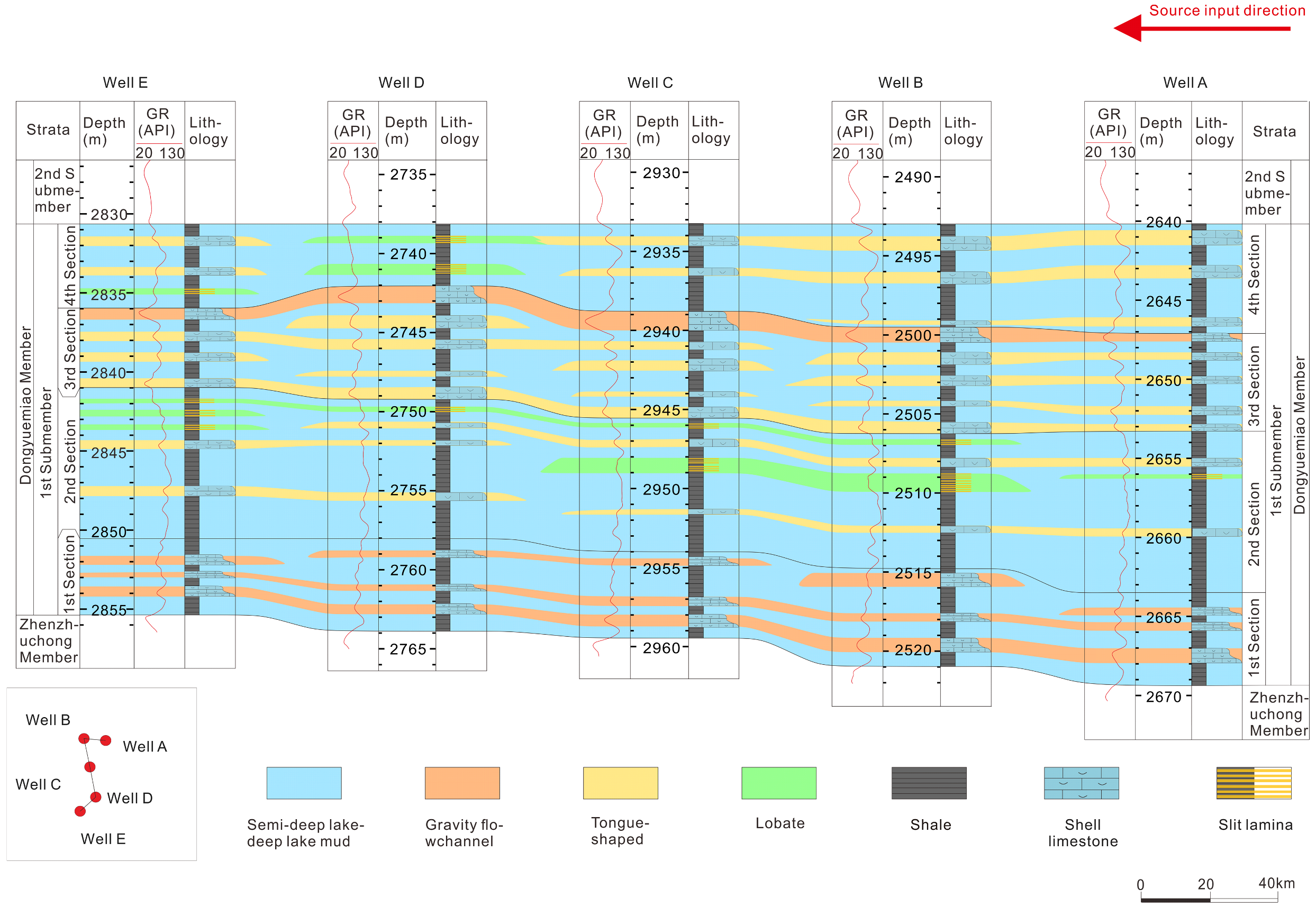
4.4. Depositional Model of Gravity-Flow Deposits

Based on the geological and sedimentary background of the Dongyuemiao Member in the study area, and combined with the lithologic and sedimentary microfacies characteristics of gravity-flow deposits, the lacustrine gravity-flow sedimentary model of the Dong 1 submember was established (Figure 9).
Based on the sedimentary background, during the sedimentary period of the Dongyuemiao Member in the Sichuan Basin, large-scale, low-energy Shell Banks were deposited in the lake basin, with the Fuling area primarily composed of semi-deep-lake and deep-lake subfacies [32]. As lake transgression began, the water level rose, causing the Shell Banks to be scoured by the lake water. The scoured shells and other sediments were deposited on the slope. Simultaneously, fine-grained sediments, such as silt and clay, were deposited under the influence of gravity. As sediment concentration increased, the pore pressure between fluids continuously rose. Due to the density differences among silt, clay, and shells, the mixed sediments were in a heterogeneous and unstable state. When the pore pressure between the sediments exceeded the viscous resistance, the gravity-flow developed and migrated along the slope due to strong lake waves, earthquakes, storms, and other factors. Gravity-flow migration led to the development of debris flows in the slope and slope break zones, while turbidity currents formed from the slope break zone toward the lake basin center.
As the gravity flow began to migrate along the gravity-flow channel toward the lake basin center, the fluid mixed with water. The internal sediment concentration and viscosity were relatively high, exhibiting viscous and non-Newtonian rheological properties consistent with the characteristics of debris flow sedimentation. The lithofacies developed during this stage mainly consisted of massive to planar laminated shell mudrock, while the sedimentary microfacies included gravity-flow channels, with shells stacked promiscuously. During the migration process, when the front of the gravity flow contacted the slope basement, a large number of shells were deposited rapidly, forming shell skeleton interlayers (Figure 2d). The gravity flow continued to advance, with a small amount of shell skeletons preferentially deposited under gravity and forming laminae (Figure 9a). As the gravity flow migrated to the slope break zone, the fluid energy weakened, leading to the deposition of medium-sized shell debris. Simultaneously, the erosion of mudstone in the lake basin by gravity flow involved muddy sediments in the flow. The lithofacies developed during this stage primarily consisted of planar laminated bioclastic mudrock, with sedimentary microfacies characterized as tongue-shaped. Under the influence of gravity and internal shear forces, the involved muddy sediments were torn, forming mud fragments distributed within the gravity flow (Figure 3g), while the size of the shells became finer (Figure 3d–f).
Figure 9. Comprehensive depositional model of different lithofacies of the first submember (modified from [33]). (a) Core assemblage of gravity flow channel. (b) Core assemblage of tongue-shaped. (c) Core assemblage of lobate.
Minerals 15 00473 g009

4.5. Pore-Structure Characteristics
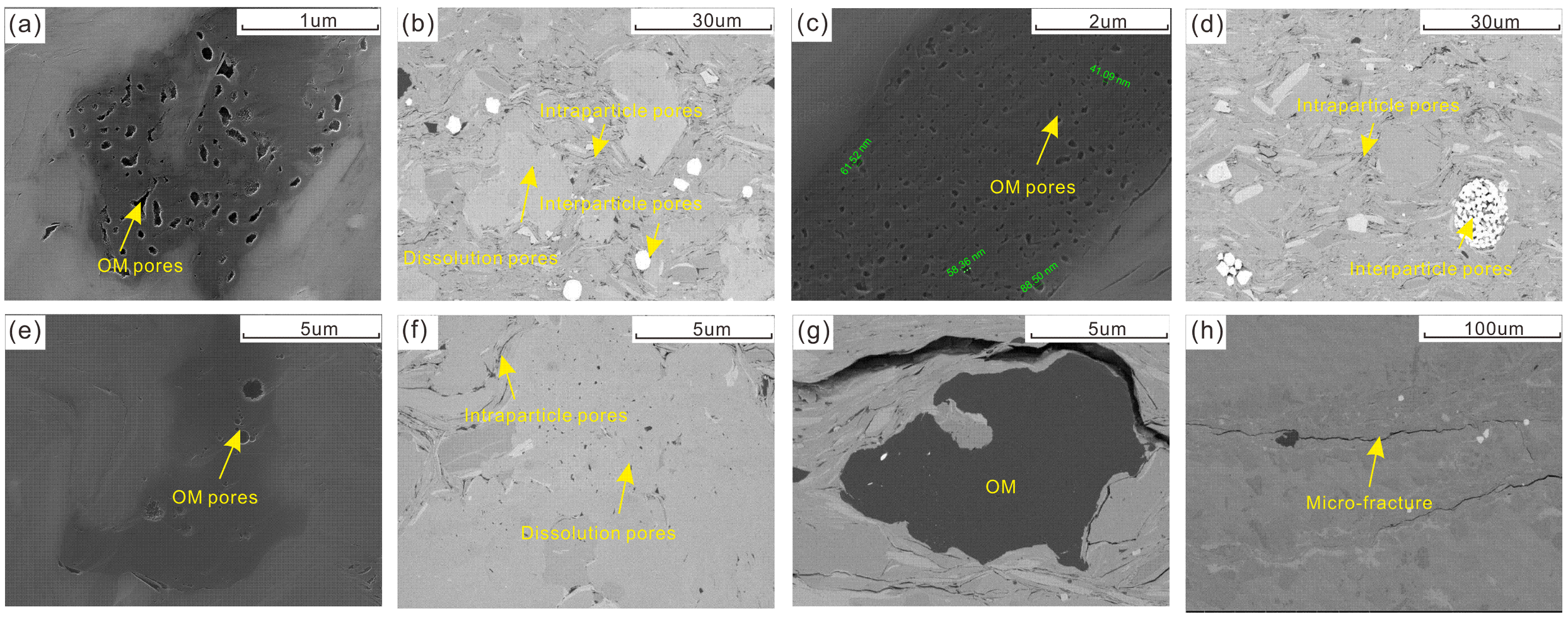
As an event deposition, the geological significance of gravity flow for lacustrine shale lies in its ability to migrate nearshore sediments to the center of the lake basin, resulting in multiple lithofacies types and enhanced reservoir heterogeneity of lacustrine shale. In the gravity-flow channel, massive to planar laminated shell mudrock predominantly developed and exhibited the poorest reservoir physical properties. The porosity ranged from 4.06% to 7.85%, with an average of 5.93%. In the tongue-shaped, planar laminated bioclastic mudrock dominated, and exhibited poor reservoir physical properties. The porosity ranged from 6.32% to 10.84%, with an average of 8.61%. To clarify the influence of gravity-flow deposition on shale reservoir pore heterogeneity, we utilized SEM, low-temperature nitrogen adsorption, and high-pressure mercury injection experiments. These methods clarified the reservoir characteristics and pore size distribution in the Dong 1 submember. Additionally, we discussed the differences in the pore structure of shale across various sedimentary microfacies and their influence on pore structure.

4.5.1. Pore Types

Based on scanning electron microscopy results, the reservoir space types in the Dong 1 submember were mainly composed of organic pores, intergranular pores, shrinkage features in clay minerals, intercrystalline pores, dissolution pores, and microfractures. Differences in pore types exist among different sedimentary microfacies, which are controlled by varying lithofacies (Figure 10). Organic pores were developed in the lobate, while sponge-like micropores and mesopores were also present and exhibited good pore connectivity. As the silt content increased, the proportion of rigid minerals, such as quartz and feldspar, also increased, leading to an increase in the number of intergranular pores. Additionally, a small number of shrinkage features and intragranular dissolved pores in clay minerals had developed. In the tongue-shaped, the development of organic pores was low, with most being elliptical mesopores. Organic acids were produced during the organic matter hydrocarbon expulsion process, which led to the extensive development of intragranular dissolved pores. The degree of organic pore development in the gravity-flow channel was low, while microfractures primarily developed around shell particles. This was attributed to the significant difference in mechanical properties between the shell particles and the shale matrix. The morphology of organic pores in semi-deep-to-deep-lake mud was characterized by near-spherical, elliptical, and irregular micropores and mesopores. Additionally, intergranular pores between framboidal pyrites were observed.

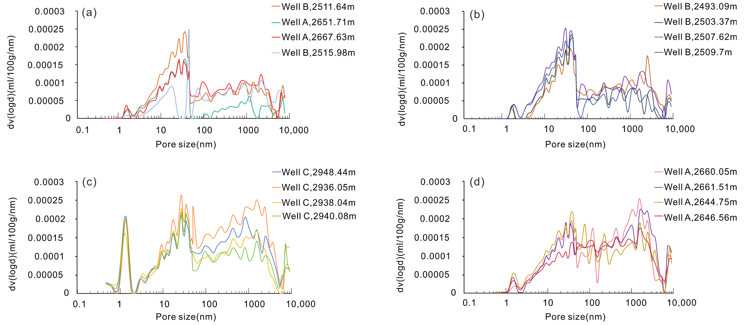
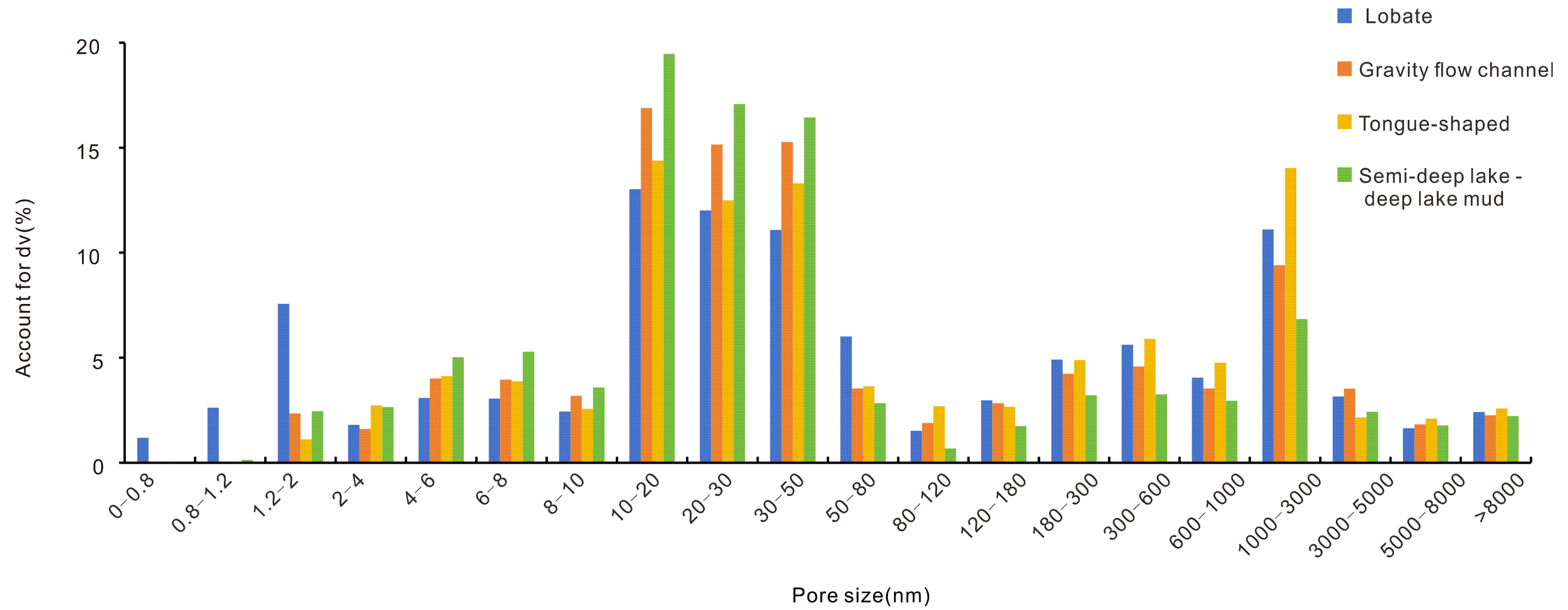
4.5.2. Pore Size Distribution

Micro-nanometer pores were primarily developed in the Dong 1 submember shale of the study area. Due to the limitations of different experimental testing ranges, a single experiment could not fully characterize the pore size distribution of shale. Therefore, this study utilized low-temperature nitrogen adsorption (0–50 nm) and high-pressure mercury intrusion (50–10,000 nm) to quantitatively characterize the pore structure. The full pore size distribution curves of shale with different sedimentary microfacies from gravity-flow deposits were obtained (Figure 11). Overall, the pore size distribution shapes of the gravity-flow channel and tongue-shaped were similar, with the main peak concentrated between 10 and 50 nm. The full pore size distribution curve of the semi-deep-lake–deep-lake-mud sedimentary microfacies exhibited a bimodal distribution, concentrated at 10–50 nm and 800–3000 nm, respectively. The full pore size distribution curve of the lobate microfacies shale exhibited a three-peak distribution, concentrated at 1–2 nm, 10–80 nm, and 600–3000 nm, respectively. Based on the full pore size distribution curves and pore volume distributions of different sedimentary microfacies (Figure 12), it could be concluded that in the lobate, micropores, and mesopores were composed of organic pores, intergranular, and intragranular pores, concentrated in 10–50 nm and 800–3000 nm, contributing more than 10% and 40% to the total pore volume, respectively. The development of shrinkage fractures between clay minerals led to a high proportion of 600–3000 nm pores, contributing approximately 15% to the total pore volume. In the semi-deep-lake–deep-lake shale, the pore sizes of organic pores were primarily mesopores. The development of various intergranular and intragranular dissolved pores resulted in a high proportion of 10–50 nm mesopores, contributing approximately 50% to the total pore volume. In the tongue-shaped shale, the development of organic pores was limited. In contrast, dissolved pores in calcite grains were highly developed, with the pore size distribution primarily concentrated between 10–50 nm, contributing approximately 35% to the total pore volume. The development of shrinkage fractures and microfractures between clay minerals resulted in a relatively high proportion of pores in 1000–3000 nm, contributing approximately 15% to the total pore volume. In the gravity-flow channel shale, organic pores were rarely observed. The development of microfractures around the shell skeleton lamina resulted in 10–50 nm and 1000–5000 nm pores contributing approximately 45% and 10% to the total pore volume, respectively. In summary, shale deposited in a gravity-flow sedimentary environment exhibited strong reservoir heterogeneity. The lobate deposit facilitated the development of organic pores characterized by micropores, intergranular pores, dissolved pores, and shrinkage fractures between clay minerals, resulting in a more homogeneous pore structure.

4.6. Effects on Pore Structure

To investigate the influence of gravity flow microfacies on shale pore structure, sixteen samples were analyzed by categorizing pore volume distributions into micropores (<2 nm), mesopores (2–50 nm), and macropores (>50 nm) according to IUPAC standards (Table 4), quantifying mineralogical composition (carbonates, silicates, and clay minerals) and total organic carbon (TOC) content, and performing correlation analysis to elucidate the interparameter relationships between these characteristics.
Existing studies have demonstrated that highly mature marine shales typically develop abundant nanoscale organic pores during hydrocarbon generation, resulting in a significant positive correlation between total organic carbon (TOC) content and pore volume [34,35,36,37,38]. However, the lacustrine shale samples from the Dongyuemiao Member in our study area exhibit markedly different characteristics. With relatively low TOC content, these shales show limited development of organic-matter-hosted pores during hydrocarbon generation. Furthermore, insufficient hydrocarbon-generation overpressure has led to the minimal formation of associated nanoscale microfractures. Consequently, both micropore (<2 nm) and macropore (>50 nm) volumes display poor correlations with TOC content. In contrast, organic acids generated during hydrocarbon maturation have significantly enhanced dissolution porosity, particularly within the mesopore range (2–50 nm), explaining the observed strong positive correlation between mesopore volume and TOC content (Figure 13a). A statistical analysis of the Dongyuemiao Member shale reveals distinct mineralogical controls on pore development. Silicate mineral content shows no significant correlation with pore volume (Figure 13b), while carbonate minerals exhibit a weak negative correlation (Figure 13c) due to their pore-filling cementation properties. In contrast, clay minerals demonstrate a strong positive correlation with pore volume (Figure 13d), primarily attributed to the substantial contribution of interlayer pores in interlayer pores of clay minerals. These results clearly establish clay mineral content as the dominant factor controlling pore development in the Dongyuemiao lacustrine shale. Additionally, a moderate positive correlation exists between TOC content and mesopore volume (2–50 nm), suggesting that organic matter primarily influences the mesopore system, rather than the total pore network.
The Fuling area’s gravity flow depositional system resulted in distinct microfacies within the Dongyuemiao Member, each exhibiting characteristic lithofacies associations. Notably, lobate deposits preferentially developed lithofacies F3, which is distinguished by significantly higher clay mineral content (60.8–69.1 wt%) and elevated TOC levels (1.53–2.45 wt%). These reservoir properties demonstrate statistically significant positive correlations, with clay mineral content strongly influencing total pore volume and TOC content specifically enhancing mesopore development (2–50 nm pores). Consequently, the F3 lithofacies within lobe deposits emerges as the most prospective shale gas reservoir unit in the study area, combining optimal geochemical characteristics with favorable pore-structure attributes.

5. Conclusions

(1) Four types of lithofacies were identified in the Dong 1 submember of the Fuling area, Sichuan Basin, corresponding to two types of gravity flow. Planar laminated shell mudrock and planar laminated bioclastic mudrock were classified as debris flow deposits, while planar laminated silty mudrock was categorized as turbidite deposits, and massive mudrock was classified as suspension deposits. Based on lithofacies types and gravity flow sedimentary characteristics, the following features were identified in the Dong 1 Member gravity flow deposit: gravity flow channels, tongue shapes, leaf bodies, and semi-deep–deep-lake mud.
(2) The Dong 1 submember in the study area primarily developed semi-deep to deep-lake mud, gravity flow channels, and tongue-shaped deposits, which were widely distributed and exhibited good lateral connectivity. Leaf bodies were deposited in the second and fourth layers of the Dong 1 submember. Under the influence of lake transgression, as water depth increased, the gravity-flow channel–tongue-shaped–lobate sedimentary system advanced toward the source direction during the sedimentary period of the Dong 1 submember. Consequently, the sedimentary center was located far from the center of the lake basin. Combining the sedimentary background, gravity flow deposition characteristics, and migration processes, we established the lacustrine gravity flow deposition model.
(3) There were differences in the pore structures of shale associated with different gravity-flow microfacies. The lobate deposit facilitated the development of organic pores, primarily consisting of micropores, intergranular pores, dissolved pores, and shrinkage fractures between clay minerals. Additionally, the high proportion of inorganic pore volume contributed to a uniform pore size distribution in the shale reservoir. The gravity flow channel deposit did not promote the development of organic and inorganic pores, resulting in weak pore-size heterogeneity in the shale reservoir. Although the tongue-shaped deposit did not promote the development of organic pores, it did facilitate the formation of dissolution pores, thereby improving the pore size distribution in the shale reservoir.
(4) The lobate deposit microfacies facilitates the development of lithofacies F3 characterized by both high clay mineral content and elevated TOC levels, while statistical analyses reveal significant positive correlations between clay mineral content and total pore volume, as well as between TOC content and mesopore volume.

Author Contributions

Conceptualization, Q.Y. and Y.G.; methodology, Y.J.; validation, Z.L.; formal analysis, X.W.; investigation, Q.Y. and Y.J.; data curation, Y.G.; writing—original draft preparation, Q.Y. and Y.J.; writing—review and editing, Z.L. and X.W.; visualization, Y.G.; supervision, Y.J.; project administration, X.W. All authors have read and agreed to the published version of the manuscript.

Funding

The research was supported by the National Natural Science Foundation of China (grant number: No. 42272171 and No. 42302166).

Institutional Review Board Statement

Not applicable.

Informed Consent Statement

Not applicable.

Data Availability Statement

Data are contained within the article.

Conflicts of Interest

Authors Zhujiang Liu and Xiangfeng Wei were employed by the Sinopec Exploration Company. The remaining authors declare that the research was conducted in the absence of any commercial or financial relationships that could be construed as a potential conflict of interest.

References

  1. Lu, Q.; Xin, H.; Wang, L.; Luo, S.; Dan, W.; Feng, S. Sedimentary types, characteristics and model of lacustrine fine-grained gravity flow in the Member 7 of Trassic Yanchang Formation in Ningxian area, Ordos Basin. J. Palaeogeogr. 2023, 25, 823–840. [Google Scholar]
  2. Yang, T.; Cao, Y.; Wang, Y.; Zhang, S. Types, sedimentary characteristics and genetic mechanisms of deep-water gravity flows: A case study of the middle submember in Member 3 of Shahejie Formation in Jiyang depression. Acta Pet. Sinica 2015, 36, 1048–1059. [Google Scholar]
  3. Zhang, J.; Li, S.; Li, H.; Zhou, X.; Liu, J.; Guo, R.; Chen, J.; Li, S. Gravity flow deposits in the distal lacustrine basin of the 7th reservoir group of Yanchang Formation and deepwater oil and gas exploration in Ordos Basin: A case study of Chang 73 sublayer of Chengye horizontal well region. Acta Pet. Sinica 2021, 42, 570–587. [Google Scholar]
  4. Middleton, G.; Hampton, M. Sediment Gravity Flows: Mechanics of Flow and Deposition. In Turbidites and Deep-Water Sedimentation; Middleton, G.V., Bouma, A.H., Eds.; Pacific Section SEPM: Los Angles, LA, USA, 1973; pp. 1–38. [Google Scholar]
  5. Lowe, D. Sediment gravity flows: Their classification and some problems of application to natural flows and deposits. In Geology of Continental Slopes; SEPM Special Publication: Los Angles, LA, USA, 1979; pp. 75–82. [Google Scholar]
  6. Lowe, D. Depositional models with special reference to the deposits of high-density turbidity currents. J. Sediment. Petrol. 1982, 52, 279–297. [Google Scholar]
  7. Shen, W.; Jin, X.; Zhao, M.; Liu, X. Discovery and significance of gravity flow deposits of Chang 6 and Chang 7 in Qilicun Oilfield, Ordos Basin. Complex Hydrocarb. Reserv. 2024, 17, 38–43. [Google Scholar]
  8. Xie, X.; Liu, L.; Tang, W.; Shen, P.; Zhang, J. Current research status and suggestions on the sublacustrine fans in China. China Offshore Oil Gas 2024, 36, 71–83. [Google Scholar]
  9. Chen, B.; Lin, C.; Ma, C.; Ren, L.; Wang, J.; Li, Z.; Du, K. Types, characteristics and sedimentary model of deep-water gravity flow deposition in the steep slope zone of terrestrial faulted lacustrine basin:a case study of the Es4s submember in the Shengtuo area of Dongying depression. Acta Geol. Sinica 2019, 93, 2921–2934. [Google Scholar]
  10. Sun, J.; Xue, J.; Hou, G.; Wu, A.; Song, M.; Zhu, F. Sedimentary characteristics and model of sandy debris flow in depression area of lacustrine basin:A case study of the Jurassic Sangonghe formation in the western well Pen-1 sag, Junggar basin. J. China Univ. Min. Technol. 2019, 48, 858–869. [Google Scholar]
  11. Mutti, E.; Ricci, L. Turbidites of the Northern Apennines: Introduction to Facies Analysis. Int. Geol. Rev. 1972, 20, 125–166. [Google Scholar] [CrossRef]
  12. Coronel, M.; Isla, M.; Veiga, G.; Mountney, N.; Colombera, L. Anatomy and facies distribution of terminal lobes in ephemeral fluvial successions: Jurassic Tordillo Formation, Neuquén Basin, Argentina. Sedimentology 2020, 67, 2341–2365. [Google Scholar] [CrossRef]
  13. Zou, C.; Feng, Y.; Yang, Z.; Jiang, W.; Zhang, T.; Zhang, H.; Wang, X.; Zhu, J.; Wei, Q. Fine-grained gravity flow sedimentation and its influence on development of shale oil sweet spot intervals in lacustrine basins in China. Pet. Explor. Dev. 2023, 50, 883–897. [Google Scholar] [CrossRef]
  14. Shu, Z.; Zhou, L.; Li, X.; Liu, H.; Zeng, Y.; Xie, H.; Yao, M.; Wang, Y. Geological characteristics of gas condensate reservoirs and their exploration and development prospect in the Jurassic continental shale of the Dongyuemiao Member of Ziliujing Formation, Fuxing area, eastern Sichuan Basin. Oil Gas Geology. 2021, 42, 212–223. [Google Scholar]
  15. Guo, X.; Wei, Z.; Wei, X.; Liu, Z.; Chen, C.; Wang, D. Enrichment conditions and exploration direction of Jurassic continental shale oil and gas in Sichuan Basin. Acta Petrolei. Sin. 2023, 44, 14–27. [Google Scholar]
  16. Schieber, J.; Souyhard, J. Bedload transport of mud by floccule ripples: Direct observation of ripple migration processes and their implications. Geology 2009, 37, 483–486. [Google Scholar] [CrossRef]
  17. Cui, H.; Zhu, S.; Shi, Z.; Sun, S.; Chang, Y.; Suo, Y. Sedimentary characteristics and development model of lacustrine fine-grained hybrid sedimentary rocks in the Jurassic Da’anzhai Member, northern Sichuan Basin. J. Palaeogeogr. 2022, 24, 1099–1113. [Google Scholar]
  18. Yang, P.; Xia, Q.; Yang, C.; Qing, S.; Chen, N. A Study on the Gravity Flow Deposits Characteristics of the Middle Jurassic Lianggaoshan Formation in the Fuling Area of the Sichuan Basin-A Case Study of Well TY1. Petrochem. Ind. Technol. 2024, 31, 283–285. [Google Scholar]
  19. Owen, M. Distinguishing seismic from storm-triggered event beds in deep-water deposits: A review and recommendations for future studies. Earth-Sci. Rev. 2020, 210, 103340. [Google Scholar]
  20. Wang, D.; Chen, C.; Liu, Z.; Yang, S.; Liu, M.; Xie, J. Main controlling factors for oil and gas enrichment in Jurassic laminated shale in Fuxing area of Sichuan Basin. Pet. Geol. Exp. 2024, 46, 319–332. [Google Scholar]
  21. Washburn, E.W. The dynamics of capillary flow. Phys. Rev. 1921, 17, 273–283. [Google Scholar] [CrossRef]
  22. Liu, H.; Sun, S.; Cao, Y. Lithofacies characteristics and distribution model of fine-grained sedimentary rock in the lower Es3 member, Dongying Sag. Pet. Geol. Recovery Effic. 2017, 24, 1–10. [Google Scholar]
  23. Hu, D.; Wei, Z.; Liu, R.; Wei, X.; Chen, F.; Liu, Z. Enrichment control factors and exploration potential of lacustrine shale oil and gas: A case study of Jurassic in the Fuling area of the Sichuan Basin. Nat. Gas Ind. 2021, 41, 113–120. [Google Scholar] [CrossRef]
  24. Lazar, O.; Bohacs, K.; Macquaker, J.; Schieber, J.; Demko, T. Capturing key attributes of fine-grained sedimentary rocks in outcrops, cores, and thin sections: Nomenclature and description guidelines. J. Sediment. Res. 2015, 85, 230–246. [Google Scholar] [CrossRef]
  25. Mohrig, D.; Ellis, C.; Parker, G.; Whipple, K.; Hondzo, M. Hydroplaning of subaqueous debris flows. Geol. Soc. Am. Bull. 1998, 110, 387–394. [Google Scholar] [CrossRef]
  26. Harbitz, C.; Parker, G.; Elverhøi, A.; Marr, J.; Mohrig, D.; Harff, P. Hydroplaning of subaqueous debris flows and glide blocks: Analytical solutions and discussion. J. Geophys. Res. Solid Earth 2003, 108, 1. [Google Scholar] [CrossRef]
  27. De, B.; Engvik, L.; Harbitz, C.; Elverhøi, A. Hydroplaning and submarine debris flows. J. Geophys. Res. Ocean. 2004, 109, 1. [Google Scholar]
  28. Talling, P. Hybrid submarine flows comprising turbidity current and cohesive debris flow: Deposits, theoretical and experimental analyses, and generalized models. Geosphere 2013, 9, 460–488. [Google Scholar] [CrossRef]
  29. Song, M.; Xiang, K.; Zhang, Y.; Cai, P.; Liu, J.; Yang, R. Research Progresses on Muddy Gravity Flow Deposits and Their Significances on Shale Oil and Gas: A case study from the 3rd oil-member of the Paleogene Shahejie Formation in the Dongying Sag. Acta Sedimentol. Sin. 2017, 35, 740–751. [Google Scholar]
  30. Clare, M.; Talling, P.; Challenor, P. Distal turbidites reveal a common distribution for large (>0.1 km3) submarine landslide recurrence. Geology 2014, 42, 263–266. [Google Scholar] [CrossRef]
  31. Cao, Y.; Yang, T.; Wang, Y.; Zhang, S.; Wang, S.; Zhang, Q.; Wang, X. Types and genesis of deep-water hybrid event beds comprising debris flow and turbidity current. Earth Sci. Front. 2016, 24, 234–248. [Google Scholar]
  32. Li, Y.; He, D. Evolution of tectonic-depositional environment and prototype basins of the Early Jurassic in Sichuan Basin and adjacent areas. Acta Pet. Sin. 2014, 35, 219–232. [Google Scholar]
  33. Xu, M.; Wang, F.; Tian, J.; Ren, Z.; Meng, H.; Yu, W.; Wang, J.; Wu, J.; Xiao, Y. Classification of Lacustrine Organic-Rich Mud Shale Petrography and the Depositional Environment: An Example from the Chang 73 Sub-member in the Ordos Basin. Acta Sedimentol. Sin. 2023, 76, 1–24. [Google Scholar]
  34. Wu, J.; Yuan, Y.; Niu, S. Multiscale characterization of pore structure and connectivity of Wufeng-Longmaxi shale in Sichuan Basin, China. Mar. Pet. Geol. 2020, 120, 104514. [Google Scholar] [CrossRef]
  35. Lu, J.; Ruppel, S.; Rowe, H. Organic matter pores and oil generation in the Tuscaloosa marine shale. AAPG Bull. 2015, 99, 333–357. [Google Scholar] [CrossRef]
  36. Chen, F.; Zheng, Q.; Ding, X. Pore size distributions contributed by OM, clay and other minerals in over-mature marine shale: A case study of the Longmaxi shale from Southeast Chongqing, China. Mar. Pet. Geol. 2020, 122, 106479. [Google Scholar] [CrossRef]
  37. Ross, D.; Bustin, R. The importance of shale composition and pore structure upon gas storage potential of shale gas reservoirs. Mar. Pet. Geol. 2009, 26, 916–927. [Google Scholar] [CrossRef]
  38. Xu, Q.; Ma, Y.; Liu, B. Characteristics and control mechanism of nanoscale pores in lacustrine tight carbonates: Examples from the Jurassic Da’anzhai Member in the central Sichuan Basin, China. J. Asian Earth Sci. 2019, 178, 156–169. [Google Scholar] [CrossRef]
Figure 1. (a) Sedimentary facies during Jurassic Ziliujing Formation, Dongyuemiao Member (J1d) deposition in the Sichuan Basin. (b) Stratigraphic column of Well C in the Study Area.
Minerals 15 00473 g001
Figure 2. Representative photographs of shell skeletal-bearing mudrock (F1). (a) Core photograph of F1, 1st section, Well B, 2515.20–2516.96 m. (b) Core photograph of F1 showing the shell skeleton is disorderly distributed Well B, 2514.25 m. (c) Core photograph of F1 showing planarparallel lamination, Well B, 2515.98 m. (d) Core photograph of F1 showing the abrupt contact between the shell skeleton interlayer and the overlying and underlying mudrock Well B, 2516.35 m. (e) Enlarged area of box in (c) suggests the surrounding of the shell is filled with mud. (f) Enlarged area of box in (d) suggests the surrounding of the shell is internally organized.
Minerals 15 00473 g002
Figure 3. Representative photographs of parallel-laminate bioclastic mudrock F2. (a) Core photograph of F2, fourth section, Well B, 2497.75–2499.43 m. (b) Core photograph of F2 showing the Wrinkled and streamline shaped shell fragment lamina Well B, 2497.75 m. (c) Core photograph of F2 showing the Wrinkled shaped shell fragment lamina Well B, 2498.88 m. (d) Enlarged area of box in (b) suggests the shell is destroyed and promiscuously stacked. (e) Enlarged area of box in (b) suggests the shell is highly destroyed. (f) Enlarged area of box in (c) suggests the shell is destroyed, becoming fragments, and arranged in layers. (g) Mud-tearing crumbs are observed in F2 Well B, 2499.37 m.
Minerals 15 00473 g003
Figure 4. Representative photographs of planar and parallel-laminated silty mudrock F3. (a) Core photograph of F3, third section, Well B, 2499.86–2501.85 m. (b) Core photograph of F3 showing the low-frequency development of silt laminae Well B, 2499.86 m. (c) Core photograph of F3 showing the high-frequency development of parallel silt laminae Well B, 2497.96 m. (d) Core photograph of F3 showing the development of silt layers and shell fragment lamina Well B,2501.51 m. (e) Enlarged area of box in (b) suggests the unequal thickness silt lamina. (f) Enlarged area of box in (c) suggests the scouring contact between silt lamina and mudstone. (g) Enlarged area of box in (d) suggests the Slit lamina and silt lens.
Minerals 15 00473 g004
Figure 5. Representative photographs of massive mudrock F4. (a) Core photograph of F4, third section, Well B, 2502.51–2504.32 m. (b) Core photograph of F4 showing the carbonized plant Well C, 2938.44 m. (c) Microscopic photograph of F4 showing the Clay minerals, quartz, and calcareous minerals, Well B, 2502.51 m. (d) Microscopic photograph of F4 showing the pyrite lamina, Well C, 2937.75 m. (e) Microscopic photograph of F4 showing the strawberry pyrite, Well C, 2938.44 m.
Minerals 15 00473 g005
Figure 6. The micro-phase characteristics and logging response of gravity flow in the first submember of the study area. (a) Logging response of gravity-flow channel. (b) Logging response of tongue shape. (c) Logging response of lobate. (d) Logging response of semi-deep-lake–deep-lake mud.
Minerals 15 00473 g006
Figure 7. Core interpretation and sedimentary microfacies of 1st submember of Well C. (a) Microfacies combination of 4th section. (b) Microfacies combination of 3rd section. (c) Microfacies combination of 2nd section. (d) Microfacies combination of 1st section.
Minerals 15 00473 g007
Figure 8. Microfacies correlation of five drilled wells of the first submember, Sichuan Basin.
Minerals 15 00473 g008
Figure 10. Microscopic photographs of different types of gravity-flow microfacies. (a) Microscopic photograph of lobate showing sponge OM pores, Well C, 2936.05 m. (b) Microscopic photograph of lobate showing dissolution pores, interparticle pores, and intraparticle pores, Well C, 2936.05 m. (c) Microscopic photograph of semi-deep-lake–deep-lake mud showing OM pores, Well C, 2946.18 m. (d) Microscopic photograph of semi-deep-lake–deep-lake mud showing interparticle pores and intraparticle pores, Well C, 2946.18 m. (e) Microscopic photograph of tongue-shaped showing OM pores, Well C, 2947.40 m. (f) Microscopic photograph of tongue-shaped showing dissolution pores and intraparticle pores, Well C, 2947.40 m. (g) Microscopic photograph of tongue-shaped showing OM, Well C, 2959.65 m. (h) Microscopic photograph of tongue-shaped showing micro-fracture, Well C, 2959.65 m.
Minerals 15 00473 g010
Figure 11. Pore size distribution of different types of gravity flow microfacies. (a) Gravity-flow channel. (b) Tongue-shaped. (c) Lobate. (d) Semi-deep-lake–deep-lake mud.
Minerals 15 00473 g011
Figure 12. Pore size percentage of different types of gravity flow microfacies.
Minerals 15 00473 g012
Figure 13. Correlations between TOC, mineral composition (silicate/carbonate/clay), and pore volume in the Dongyuemiao Member shale. (a) The correlation between TOC and pore volume. (b) The correlation between silicate mineral content and pore volume. (c) The correlation between carbonate mineral content and pore volume. (d) The correlation between clay mineral content and pore volume.
Minerals 15 00473 g013
Table 1. Characteristics and division of lithofacies types in the research area.
Lithofacies TypesSedimentary CharacteristicsGenetic Interpretation
shell skeletal-bearing mudrock (F1)gray–white shell skeletal floats in the mudstone,
abrupt contact between mudstone and shell, the shell skeleton is disorderly distributed
debris flow deposit
parallel–laminate bioclastic mudrock (F2)gray–white laminae, sedimentary deformation occurs in the shell clastic laminae, develop mud-tearing crumbs
planar and parallel-laminated silt mudrock (F3)gray laminae, scouring contact between silt laminae and mudstone, positive rhythm structureturbidite deposit
massive mudrock (F4)gray–black mudstone develops carbonized plant debris and framboidal pyritesuspension deposit
Table 2. TOC values and mineral composition of Dongyuemiao Member shale samples.
Well NameDepth/mTOC/%Mineral Composition/%
QuartzK-Feldspar PlagioclaseCalciteDolomitePyriteClay Minerals
Well C2948.441.53 24.21.13.42.10.01.068.2
Well C2936.052.45 24.11.43.50.00.01.969.1
Well C2938.041.68 19.40.93.58.50.02.360.8
Well C2940.081.85 25.21.33.70.00.01.365.3
Well A2660.051.58 26.61.53.76.90.00.061.3
Well A2661.511.83 29.61.02.811.20.00.754.7
Well A2644.751.84 21.01.02.025.16.82.042.1
Well A2646.561.76 18.50.81.929.43.22.040.3
Well B2493.091.5325.01.54.50.00.01.567.5
Well B2503.371.20 26.71.14.13.40.00.863.9
Well B2507.621.94 28.30.83.810.30.00.056.8
Well B2509.71.89 28.41.24.52.60.00.063.3
Well B2511.641.31 14.40.02.546.90.02.130.5
Well A2651.711.77 19.20.92.429.23.12.738.9
Well A2667.631.98 21.91.12.520.90.00.053.6
Well B2515.981.69 29.60.04.428.00.00.031.0
Table 3. Clay mineral abundance (wt%) in the Dongyuemiao Member shale samples.
Well NameDepth/mTOC/%Clay Mineral Abundance/%
IlliteKaoliniteChloriteIllite-Smectite Mixed-Layer
Well C2948.441.53 40142323
Well C2936.052.45 38162719
Well C2938.041.68 46112518
Well C2940.081.85 40152421
Well A2660.051.58 38172916
Well A2661.511.83 36202519
Well A2644.751.84 38222218
Well A2646.561.76 41172517
Well B2493.091.5345162415
Well B2503.371.20 43152616
Well B2507.621.94 37193014
Well B2509.71.89 4317328
Well B2511.641.31 3922363
Well A2651.711.77 36262612
Well A2667.631.98 3641518
Well B2515.981.69 3224377
Table 4. Pore volume distribution of Dongyuemiao Member shale samples.
Well NameDepth/mMicropore VolumeMesopore VolumeMacropore Volume
Well C2948.440.00130.00400.0032
Well C2936.050.00120.00480.0045
Well C2938.040.00110.00420.0026
Well C2940.080.00130.00410.0025
Well A2660.050.00010.00350.0028
Well A2661.510.00010.00320.0031
Well A2644.750.00020.00390.0025
Well A2646.560.00010.00250.0026
Well B2493.090.00010.00340.0022
Well B2503.370.00010.00400.0015
Well B2507.620.00020.00530.0021
Well B2509.70.00020.00480.0012
Well B2511.640.00010.00480.0017
Well A2651.710.00010.00340.0006
Well A2667.630.00010.00320.0020
Well B2515.980.00010.00170.0018
Disclaimer/Publisher’s Note: The statements, opinions and data contained in all publications are solely those of the individual author(s) and contributor(s) and not of MDPI and/or the editor(s). MDPI and/or the editor(s) disclaim responsibility for any injury to people or property resulting from any ideas, methods, instructions or products referred to in the content.

