Article

Research on the Dry Deep Flip-Flow Screening of Ilmenite and Its Pre-Throwing Tail Processing Technology

1
School of Chemical Engineering and Technology, China University of Mining and Technology, Xuzhou 221116, China
2
Jiangsu Hewa Screening Product Co., Ltd., Xuzhou 221116, China
3
International Joint Laboratory of Minerals Efficient Processing and Utilization, Ministry of Education, Xuzhou 221116, China
4
Jiangsu International University Cooperation Laboratory of Resource Low Carbon Processing & Utilization, China University of Mining and Technology, Xuzhou 221116, China
*
Authors to whom correspondence should be addressed.
Minerals 2025, 15(3), 308; https://doi.org/10.3390/min15030308
Submission received: 31 January 2025 / Revised: 22 February 2025 / Accepted: 10 March 2025 / Published: 16 March 2025
(This article belongs to the Special Issue Advances in the Theory and Technology of Physical Separation)

Abstract

:
Screening is a key step in the mineral process of ilmenite. As the grading particle size decreases, the phenomenon of clogged holes on the screening-plate intensifies, the screening environment deteriorates, and the screening effect deteriorates, seriously restricting subsequent sorting operations. This study proposes a 1 mm dry flip-flow screening method for ilmenite to achieve efficient deep classification of fine-grained materials. Firstly, a laser displacement testing system is used to study the dynamic characteristics of the flip-flow screen; based on the characteristics of different feed particle sizes, further research is conducted on the 1 mm dry flip-flow screening effect of ilmenite under different ratios of obstructive particles and difficult-to-screen particles. The 1 mm screening effect can reach 85.41%. Finally, the pre-throwing tailings process based on 1 mm multi-stage screening is put forward. This pre-throwing tail process has the characteristic of not using water and is suitable for sorting in arid, water deficient, and high-altitude frozen soil areas. It has important promotion and application value.

Graphical Abstract

1. Introduction

Titanium, a crucial metal, serves as an essential constituent in the fabrication of high-strength and lightweight alloy materials [1,2]. Titanium predominantly occurs in minerals such as ilmenite. In recent years, with the continuous intensification of exploration and mining endeavors for ilmenite, and considering the extensive yet uneven distribution of ilmenite mineralization zones, ilmenite resources currently exhibit characteristics of low grade, complex associated minerals, and challenging development [3,4]. Thus, the development and utilization of ilmenite hold great significance.
Mineral processing can accomplish the enrichment and separation of useful minerals and is the fundamental technology for the efficient and clean utilization of mineral resources [5]. As the grade of ilmenite declines, particularly when the grain size of valuable components becomes finer, the raw ore needs to be thoroughly crushed and liberated through finer grinding. The finer the crushing and grinding particle size, the more readily useful minerals can be liberated, leading to higher efficiency in subsequent separation operations and a higher comprehensive recovery rate of useful minerals [6,7,8]. With the reduction in the raw ore particle size, it becomes necessary to further lower the lower limit of the classification particle size.
Screening is a pivotal step in the efficient and clean utilization of mineral resources. Its principle involves classifying materials into two or more different size fractions based on their particle size [9,10,11]. It mainly undertakes functions such as preparation screening, inspection screening, desliming screening, dewatering screening, desliming screening, and tailings dry discharge in mineral processing [12,13,14,15,16,17,18]. In the traditional dry screening process, the screened particles tend to become stuck on the screen surface and adhere to form aggregates, resulting in difficult stratification, the phenomenon of screen surface hole blinding intensifies, reduced processing capacity, and decreased screening efficiency [19,20,21,22,23]. Consequently, efficient dry deep screening technology has always been at the forefront and a research hotspot in the field of screening.
At present, a series of studies have been conducted both domestically and internationally on the screening of 6 mm and 3 mm. Yu et al. established a dynamic model of a vibrating flip-flow screen and verified through experiments that the vibrating flip-flow screen has good performance in screening sticky fine particles of 3 mm [24]. Chen et al. constructed a DEM-FEM coupled simulation model to study the motion of particles during the flip-flow screening process [25]. Akbari et al. optimized the separation performance technology by proposing a flip-flow screening technology based on airflow enhancement [26]. As the ore grade decreases, especially for minerals with finer disseminated grain size such as ilmenite, it is necessary to further break through the lower limit of dry screening to 1 mm. Through 1 mm screening, materials can be effectively separated, improving the efficiency of subsequent beneficiation processes, reducing the loss of useful minerals, and reducing the mechanical load on subsequent equipment. For the beneficiation process of ilmenite, fine ilmenite particles can be screened out in advance through 1 mm screening, avoiding them from entering the grinding stage and being over ground, which improves the recovery rate of ilmenite and effectively reduces the energy consumption of grinding equipment.
The flip-flow screen is based on the principle of double mass sub-resonance. Driven by the fixed frame and floating frame of the flip-flow screen, the polyurethane screen plate experiences alternating relaxation and tension, generating significant acceleration [27,28]. This can effectively facilitate the rapid loosening and stratification of ilmenite, thereby achieving efficient screening. At present, the flip-flow screen has basically achieved large-scale and efficient 3 mm dry screening of fine-grained materials, but there is relatively little research on the 1 mm high-efficiency dry screening technology and theory.
Consequently, this study puts forward a 1 mm dry flip-flow screening approach for ilmenite. Initially, the dynamic characteristics of the screening body during the screening process were investigated. Subsequently, further research was carried out on the 1 mm dry screening performance of ilmenite under different feed particle-size characteristics, validating the effectiveness of this method. Finally, the pre-throwing tailings process based on 1 mm multi-stage screening is put forward.

2. Experimental System and Materials

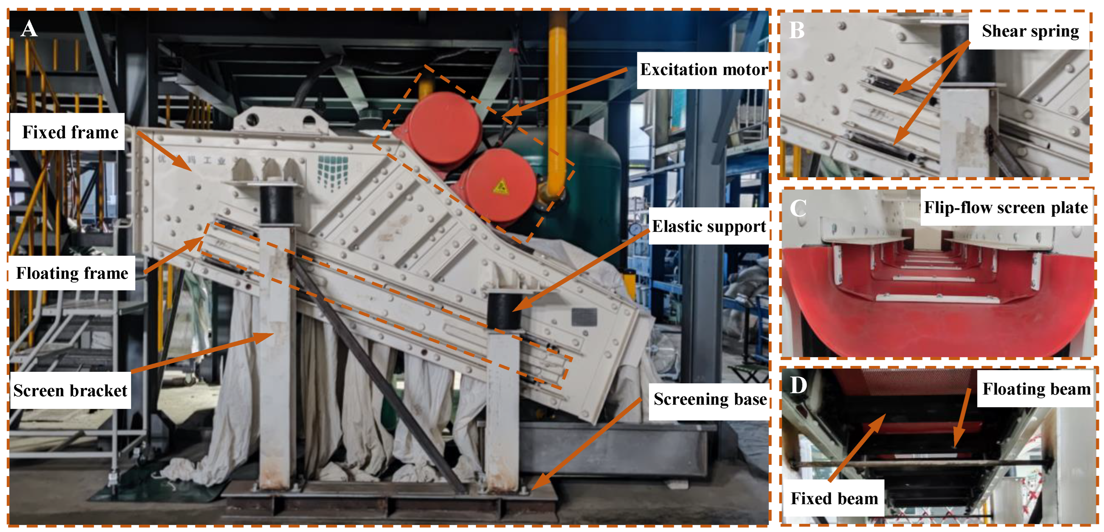
2.1. Flip-Flow Screening Experimental System

This study established the flip-flow screening experimental system for conducting 1 mm dry deep flip-flow screening experiments of fine-grained ilmenite. The system mainly includes key structures such as floating frame, fixed frame, excitation motor, elastic support, screen bracket, screen base, floating beam, fixed beam, flip-flow screen plate, shear spring, etc. In Figure 1A, the excitation motor is located above the fixed frame and two motors are arranged in parallel to generate vibration excitation for the screen; The elastic support is located above the bracket and connected to the fixed frame, mainly used for shock absorption. The fixed frame and floating frame are connected by a shear spring, as shown in Figure 1B. The schematic diagram of the structure of the flip-flow screen plate is shown in Figure 1C,D, with both ends connected to the floating beam and the fixed beam, respectively.

2.2. Evaluation Indicators for Flip-Flow Screening Effect

During the screening process of ilmenite, due to the inability of particles to pass through 100%, a portion of fine particles appeared in the oversized product; at the same time, due to the deformation of the elastic screen holes, some coarse particles appeared in the underflow products through the screen holes. Therefore, in the actual screening process, it is necessary to evaluate the screening performance of the flip-flow screen, and the specific calculation is as follows, and the definition of each parameter is shown in Table 1.
M c = 100 × γ c × O f
M f = 100 × γ f × U c
M o = M c + M f
η = E c + E c 100
E c = γ c M c γ c , t × 100
E f = γ f M f γ f , t × 100

2.3. Characterization of ILMENITE

The screening test utilized dry ilmenite raw ore with particle size distribution divided into seven fractions: 6–4 mm, 4–3 mm, 3–2 mm, 2–1 mm, 1–0.71 mm, 0.71–0.5 mm, and 0.5–0 mm. Elemental analysis of the ilmenite ore was conducted using inductively coupled plasma optical emission spectroscopy (ICP-OES). The iron content was determined to be 13.046%, while titanium constituted 3.490% of the total composition.

3. Results and Discussion

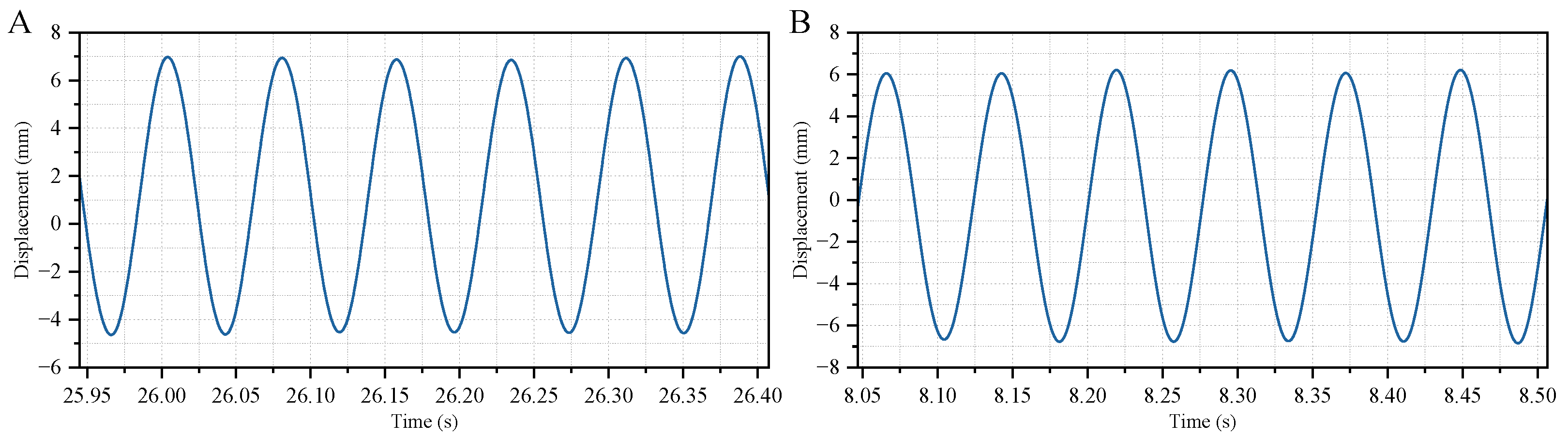
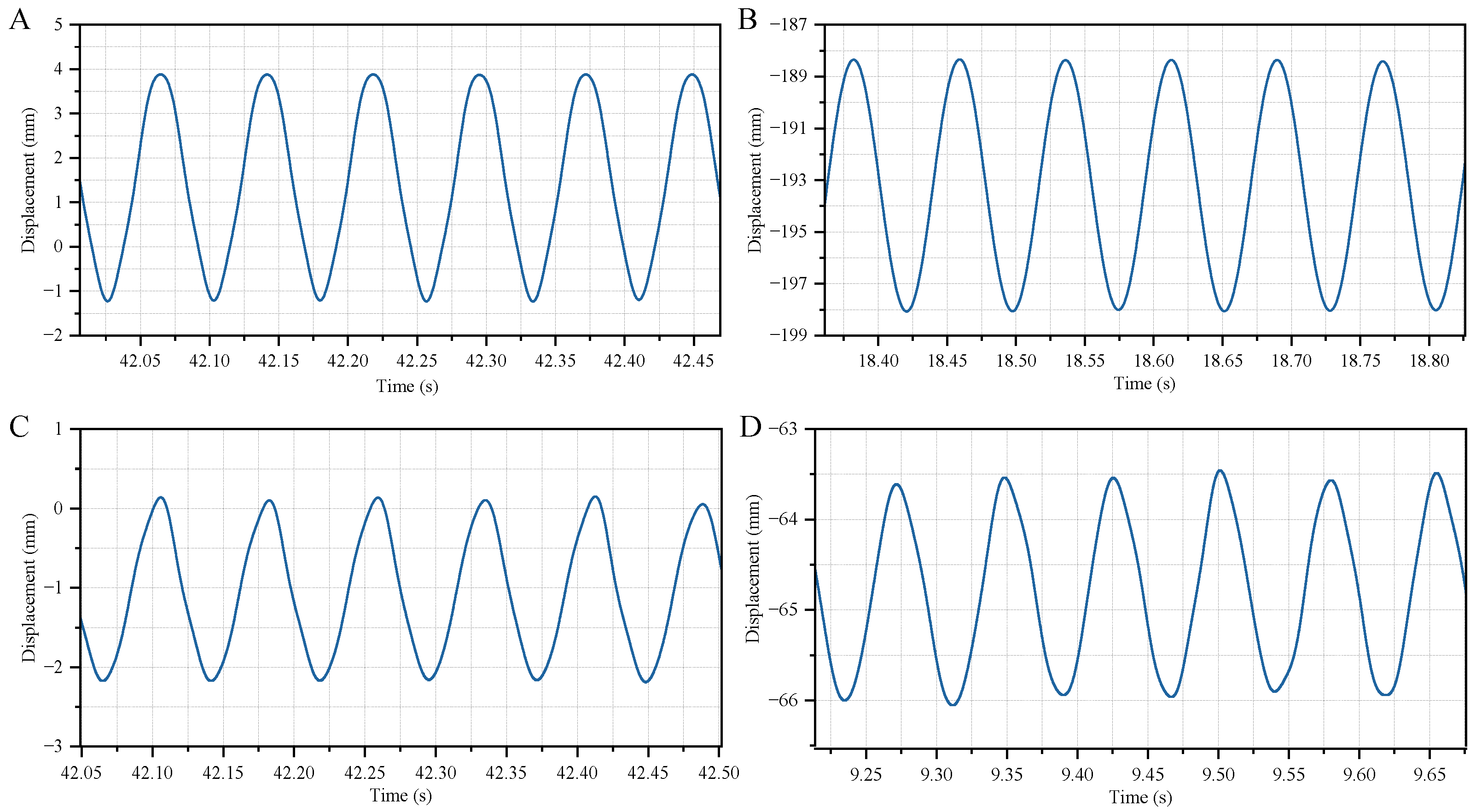
3.1. Dynamic Characteristics and Spatial Motion Trajectory of Flip-Flow Screen

This study employed a laser displacement sensor based on the triangulation measurement method for dynamic testing. Specifically, the laser emitter projected the laser beam onto the surface of the tested screen-body. Subsequently, the scattered laser beam from the screen-body was captured by the camera within the receiver. The displacement of the object was calculated by measuring the distance between the laser beam and the screen-body. The flip-flow screen-body mainly consisted of a floating frame and a fixed frame, which were connected by a shear spring. During the screening process, the flip-flow motion of the screening body was achieved through the alternating movement of the floating frame and the fixed frame. Therefore, this study focused on the dynamic characteristics of the flip-flow screen floating frame and fixed frame.
Due to the fact that the floating frame mainly moves along the direction of material flow, the displacement in the other two directions remains almost unchanged. Therefore, the focus is on studying the time-varying characteristics of displacement in this direction. Firstly, experiments were carried out on the feeding area, middle area, and discharge area of the screen-body. The displacement changes of each measuring point on the floating frame of the screen-body over time were obtained, as presented in Figure 2. From the graph, it is evident that as time progresses, the displacement of each measuring point demonstrates periodic variations.
In Figure 2A, the displacement range of the feeding end of the screen-body floating frame is from −5 mm to 7 mm, and the amplitude of the feeding end movement of the screen-body floating frame is 12 mm. In Figure 2B, the displacement range of the discharge end of the screen floating frame is from −7 mm to 6 mm, and the amplitude (the difference between the highest and lowest points of the movement) of the discharge end of the screen floating frame is 13 mm. The displacement magnitudes of the floating frame, in descending order, are: discharge area, feeding area.
Regarding the fixed frame of the screen-body, it primarily adheres to the direction of material flow and the normal direction perpendicular to the material flow. Herein, the x-axis direction denotes the movement direction along the material flow, while the y-axis direction represents the direction normal to the material flow. The time-varying displacement curves of the feeding and discharging ends of the screen-body’s fixed frame along the x- and y-axes are depicted in Figure 3. As time elapses, the displacements of the feeding and discharging ends of the screen-body’s fixed frame in the x and y directions exhibit periodic fluctuations.
In the feeding area illustrated in Figure 3A,B, the displacement range of the screen-body’s fixed frame along the x-axis is from −1.25 mm to 4 mm, and the displacement range along the y-axis is from −198 mm to 188 mm. Evidently, the variation in displacement amplitude along the y-axis is significantly greater than that along the x-axis. In Figure 3C,D, within the discharge area, the displacement range of the screen-body’s floating frame along the x-axis is from −2.25 mm to 0.25 mm, and the displacement range along the y-axis is from −66 mm to 62 mm. Along the material flow direction, the displacement amplitude of the feeding area of the screen-body’s fixed frame is larger than that of the discharging area. Along the normal direction of the material flow, the displacement amplitude of the discharge area is greater than that of the feeding area. As can be observed from the figure below.

3.2. Influence of Particle-Size Distribution on the 1 mm Flip-Flow Screening Performance of Ilmenite

The foregoing research successfully derived the dynamic characteristics of the flip-flow screen. These characteristics enabled the stable operation of the screen-body and further facilitated the 1 mm screening experiment research on ilmenite. During the flip-flow screening process, the particle-size distribution characteristics of different materials played a crucial role. They affected both the probability of particles coming into contact with the screen-mesh and the probability of particle groups passing through the screen, ultimately influencing the final screening efficiency. In particular, for materials with particle sizes close to the screen aperture, the impact of particle-size distribution characteristics on the flip-flow screening performance was even more pronounced. Based on these findings, this section focused on exploring how the particle-size distribution characteristics of materials with sizes close to the screen aperture affected the screening performance of ilmenite, aiming to provide guidance for practical production.
Regarding particles with sizes close to the screen aperture, in combination with traditional particle-size classification methods in the screening process, and according to the screening difficulty of particles, they were classified into four categories: coarse particles (6–4 mm, 4–3 mm, 3–2 mm, 2–1.5 mm), hindering-particles (1.5–1 mm), difficult-to-screen particles (1–0.71 mm), and easy-to-screen particles (0.71–0.5 mm, 0.5–0 mm). Among these, hindering-particles and difficult-to-screen particles were the particle-size grades close to the screen aperture size. Meanwhile, the external moisture content of the materials was tested before and after each experiment. Due to the evaporation of moisture during the experiment, there was a certain difference in the external moisture content before and after the experiment, and the external moisture content of the materials was tested to be between 1.1% and 1.6%.

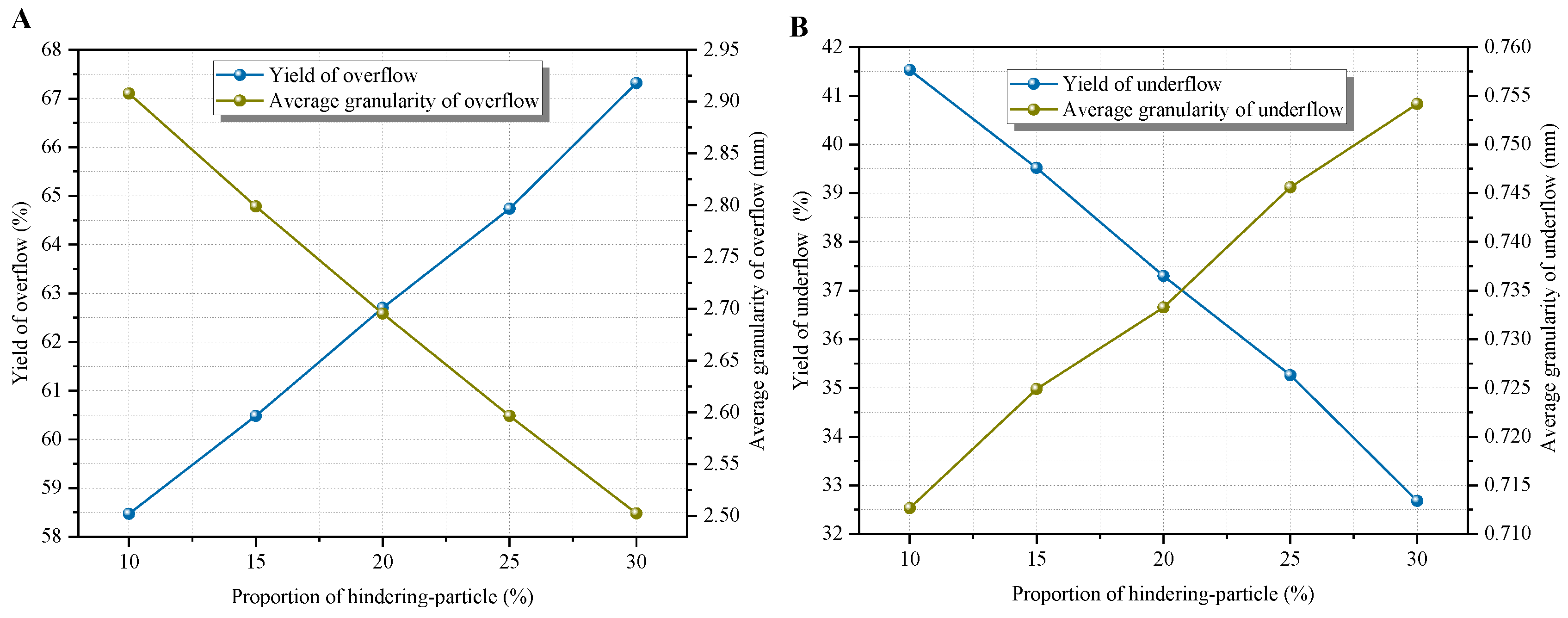
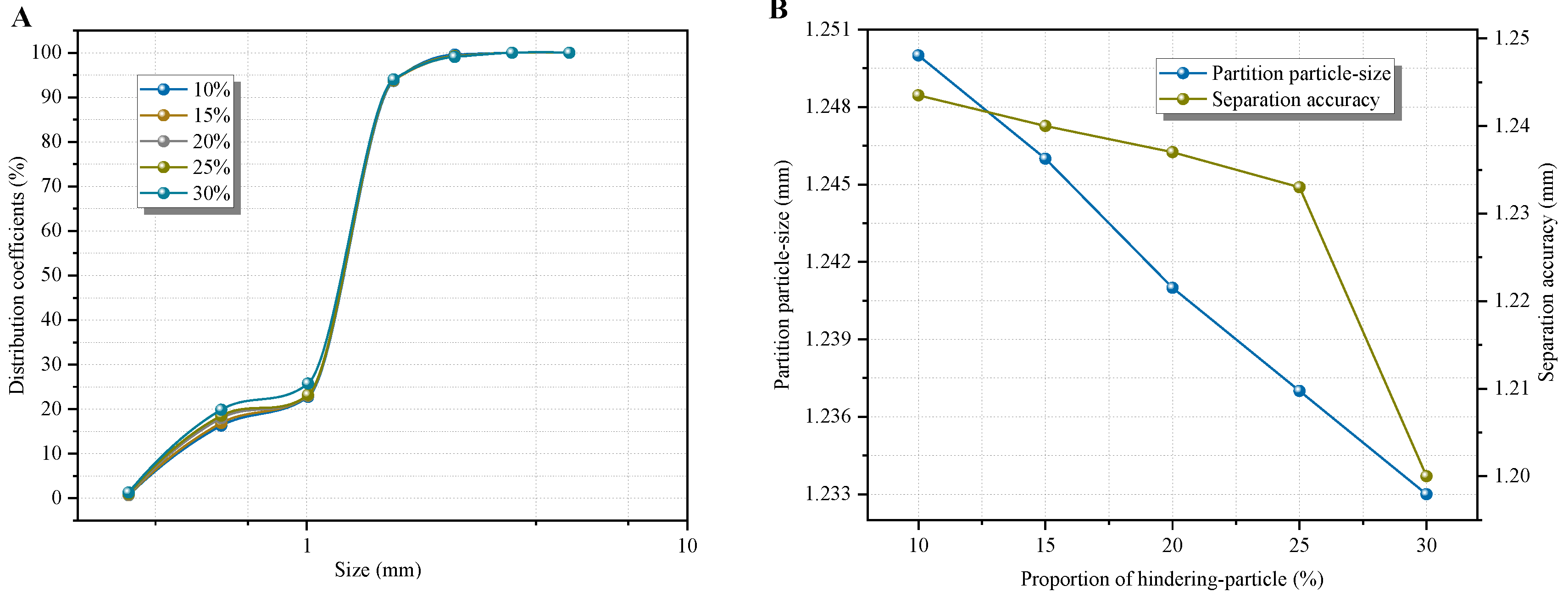
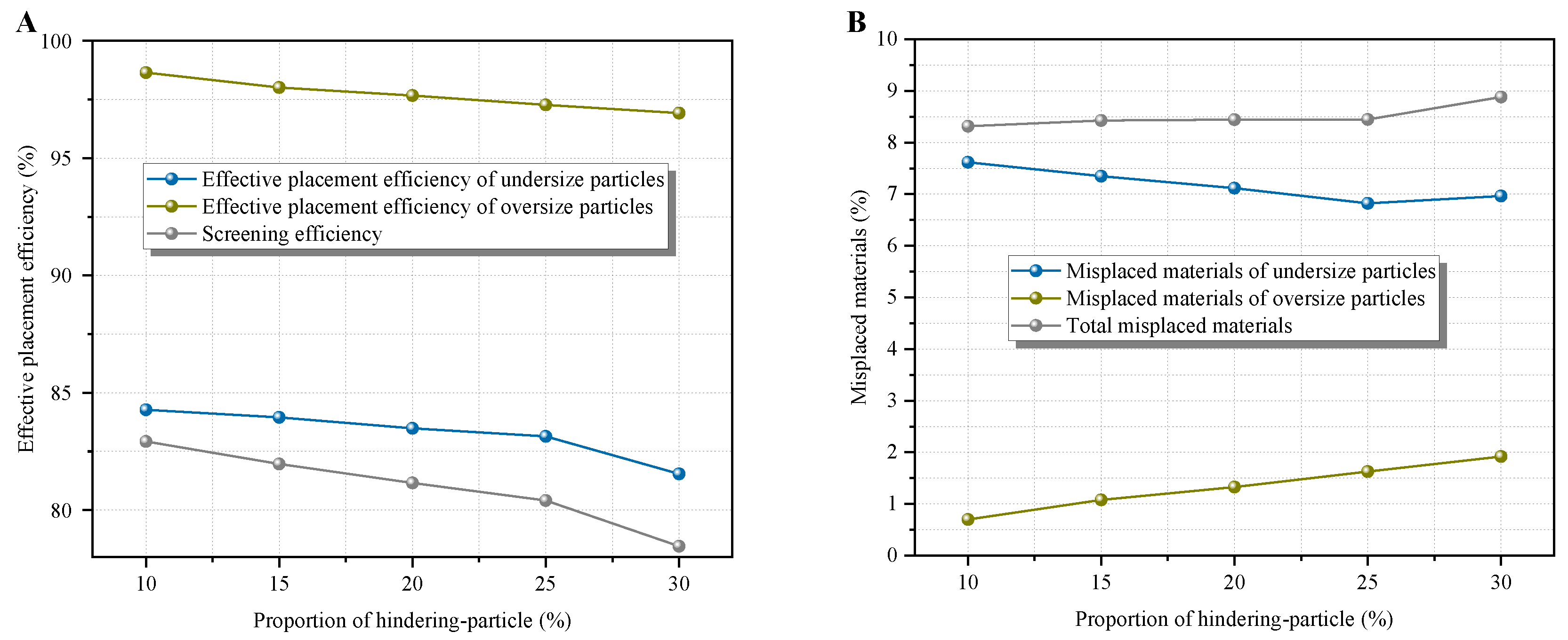
3.2.1. Influence of Particle-Size Distribution of Hindering Particle on the 1 mm Flip-Flow Screening Performance of Ilmenite

Given that the material within the 2–1 mm particle-size range was predominantly concentrated in the 1.5–1 mm range, and the quantity of material within the 2–1.5 mm particle-size range was extremely limited. For the sake of statistical convenience and calculation accuracy, the particle-size range of 2–1 mm was adopted to represent obstructive particles. The core objective of this study was to examine the influence of the gradation characteristics of hindering-particles and difficult-to-screen particles on the deep screening efficiency of the dry screening process.
The variations in the yield and weighted average particle size of the products obtained from dry deep flip-flow screening under different particle-size distribution conditions were presented in Figure 4. In Figure 4A, as the proportion of hindering-particles rose, the yield of the screened product showed a gradual increase, spanning from 58.47% to 67.32%. Concurrently, the weighted average particle size gradually diminished, ranging from 2.5 mm to 2.91 mm. In Figure 4B, with the gradual increase in the proportion of hindering-particles, the yield of the screened product gradually declined, within the range of 32.68% to 41.53%. Meanwhile, the weighted average particle size gradually increased, varying from 0.71 mm to 0.75 mm.
In Figure 5, as the proportion of hindering-particles gradually increased from 10% to 30%, the upper limit rate of the dry deep flip-flow screening product gradually increased, ranging from 1.68% to 5.87%, and the lower limit rate gradually decreased, ranging from 10.34% to 13.03%.
The distribution rate of materials with different particle sizes in the screened product under different hindering particle-size distribution conditions was depicted in Figure 6. As the proportion of hindering-particles increased, the distribution curve gradually shifted to the left. Regarding the distribution rate of materials of the same particle size, the larger the proportion of hindering-particles in the screened feed, the greater the amount of material of that particle size in the screened product. In Figure 6B, as the proportion of hindering-particle rose, their particle-size distribution gradually decreased, ranging from 1.23 mm to 1.25 mm. Simultaneously, the separation accuracy gradually declined, with a range from 0.19 mm to 0.22 mm.
The alterations in the screening efficiency and total mismatch content of the flip-flow screen under different particle size distribution conditions were presented in Figure 7. In Figure 7A, as the proportion of obstructive particles increased, both the positive blending ratios of materials with particle sizes less than 1 mm in the undersized product and materials with particle sizes greater than 1 mm in the oversized product decreased. Meanwhile, the overall dry deep flip-flow screening efficiency also declined from 82.92% to 78.46%. In Figure 7B, as the proportion of hindering particles gradually rose, the total mismatch content of dry deep flip-flow screening gradually increased from 8.32% to 8.88%.

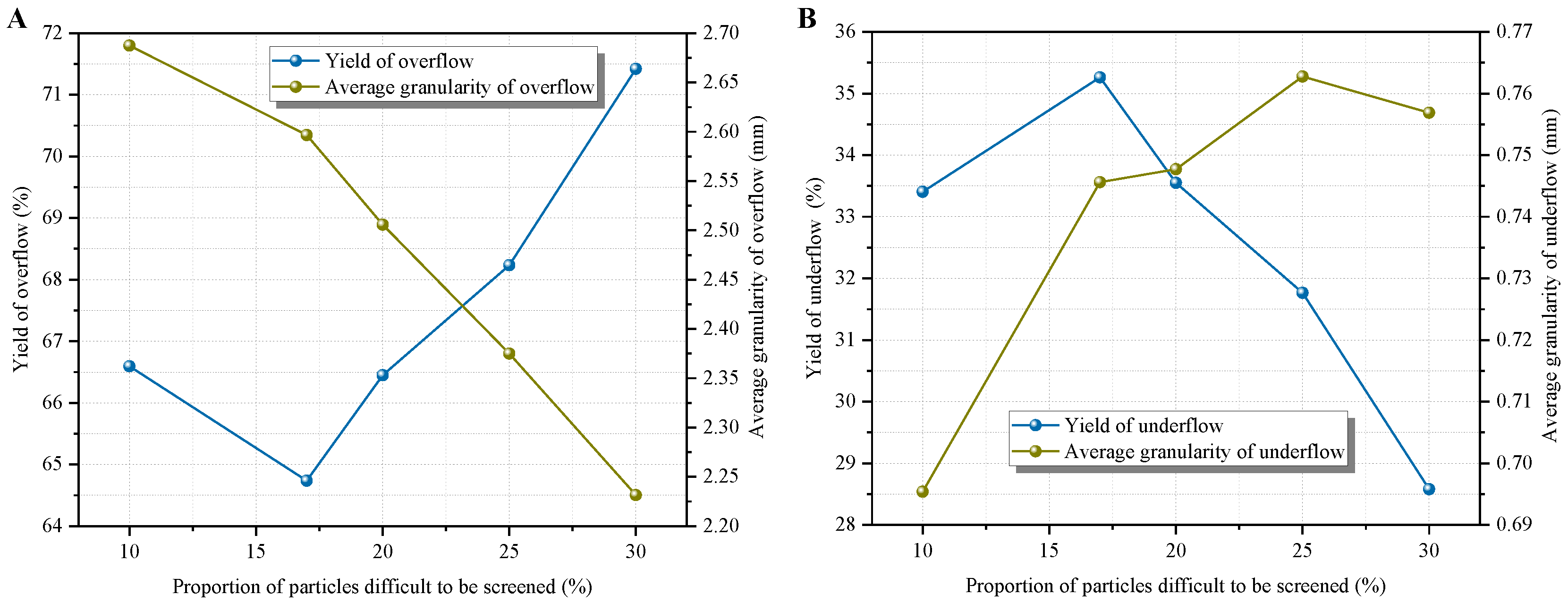
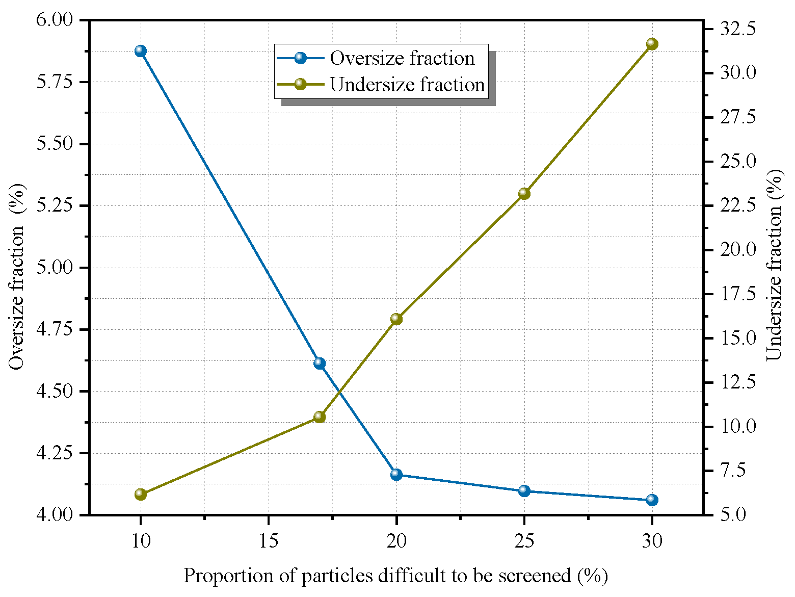
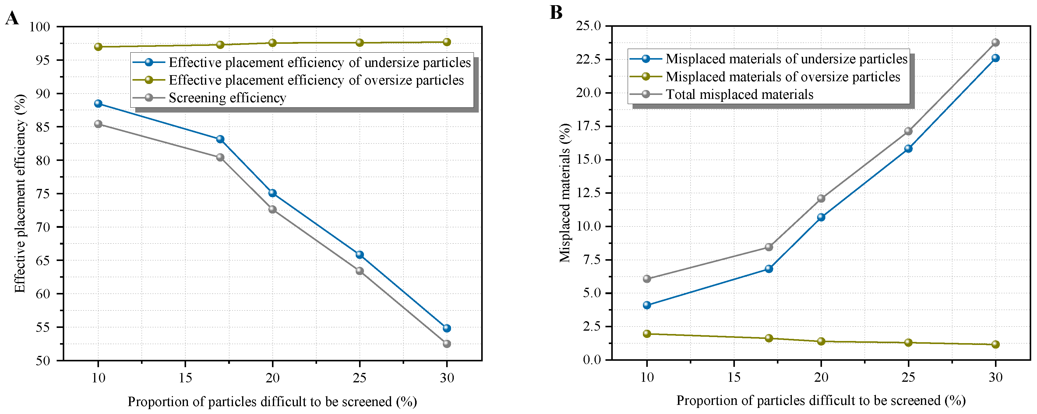
3.2.2. Influence of Particle-Size Distribution of Particle Difficult to Be Screened on the 1 mm Flip-Flow Screening Performance of Ilmenite

The variations in the yield and weighted average particle size of the products from dry deep flip-flow screening under different difficult particle-size grading conditions were presented in Figure 8. In Figure 8A, as the proportion of difficult-to-screen particles increased, the yield of the screened product initially decreased and then increased. Meanwhile, the weighted average particle size of the screened material gradually diminished. In Figure 8B, the yield of the screened material first increased and then decreased. Correspondingly, its weighted average particle size first rose and then fell.
In Figure 9, as the proportion of difficult-to-screen particles increased, the upper limit rate of dry deep screening products gradually decreased within the range of 10% to 30%, specifically from 4.06% to 5.88%. Meanwhile, as the proportion of difficult-to-screen particles gradually rose, the lower limit rate of dry deep flip-flow screening products gradually increased, ranging from 6.17% to 31.65%.
Evidently, the trend of the lower limit rate was more notable. This was mainly because as the proportion of difficult-to-screen particles increased, their particle size was slightly smaller than the screen hole size, classifying them as fine-grained materials. Moreover, the lower limit rate reflected the scenario where fine-grained materials failed to pass through the screen. Consequently, as the proportion of such materials increased, more fine-grained materials faced difficulties in passing through the screen. On the other hand, this also demonstrated that the lower limit rate was more sensitive to the changes in difficult-to-screen particles.
The distribution rate of each particle size in the flip-flow screening product under different particle-size distribution conditions was presented in Figure 10. As the proportion of difficult-to-screen particles increased, the distribution curve of the flip-flow screening products gradually shifted to the left. Regarding the distribution rate of materials of the same particle size, the larger the proportion of difficult-to-screen particles in the screened feed, the greater the amount of material of that particle size in the screened product. In Figure 10B, as the proportion of difficult-to-screen particles rose, the particle-size distribution gradually decreased, ranging from 0.89 mm to 1.28 mm. Simultaneously, the separation accuracy gradually declined, with a range from 0.16 mm to 0.38 mm.
The alterations in the screening efficiency and total mismatch content of the dry deep flip-flow screen under different particle-size distribution conditions were depicted in Figure 11. In Figure 11A, as the proportion of difficult-to-screen particles increased, the positive blending ratio of materials smaller than 1 mm in the undersized product decreased, while that of materials larger than 1 mm in the oversized product increased. Consequently, the overall screening efficiency of the screen gradually declined from 85.41% to 52.49%. In Figure 11B, as the proportion of difficult-to-screen particles rose, the total mismatch content of the dry deep flip-flow screen gradually increased from 6.07% to 23.76%.

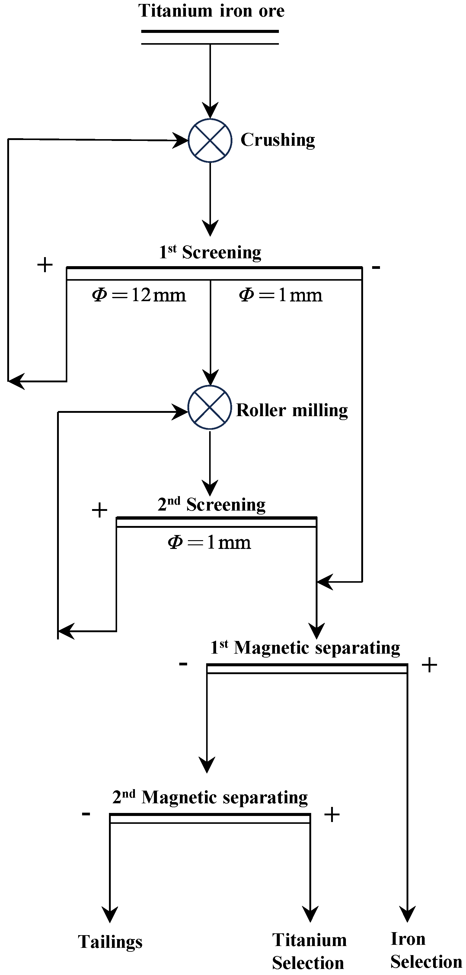
3.3. Pre-Throwing Tailings Process for Ilmenite Based on 1 mm Multi-Stage Dry Screening

The aforementioned study validated the feasibility of the 1 mm dry screening technology for ilmenite from two perspectives: the dynamic characteristics of flip-flow screening and the impact of the feed particle-size characteristics on the 1 mm screening efficiency. Consequently, a tail-discarding sorting process for titanium-iron ore based on 1 mm dry multi-stage screening was put forward, as depicted in Figure 12.
The ilmenite raw ore was initially crushed, and the crushed product then proceeds to the first screening operation. The first screening utilized double-layer screen. The upper screen aperture was set at 12 mm, which could be adjusted in accordance with the crushing process requirements. The lower screen aperture was 1 mm. The +12 mm coarse product was returned to the crushing operation, while the 12–1 mm product was fed into the dry grinding operation, which employed a high-pressure roller mill. The grinding products were then directed to the second screening operation. The second screening used a 1 mm single-layer screen. The oversized product on the +1 mm was re-introduced into the dry grinding operation. The undersize product screened by the −1 mm was combined with the undersize product from the first screening and then enters first and second dry magnetic separation operations. Through two-stage strong magnetic separation and weak magnetic separation operations, titanium rough concentrate, iron rough concentrate, and tailings could be obtained. Moreover, the dry pre-tailing disposal of ilmenite tailings was successfully achieved.
This process reduced the number of fine particles entering the high-pressure roller mill through 1 mm multi-stage dry screening, which could effectively avoid excessive crushing of materials; at the same time, it reduced grinding energy consumption and achieved energy conservation and emission reduction. This pre-throwing tail process had the characteristic of not using water and was suitable for sorting in arid, water deficient, and high-altitude frozen soil areas. It has important promotion and application value.

4. Conclusions

As the lower limit of particle-size decreased, the difficulty of dry deep screening also increased. In response to the industry challenge of reducing the lower limit of screening from 6 mm and 3 mm to 1 mm, this study proposes a 1 mm dry flip-flow screening method for ilmenite to achieve effective deep classification of fine-grained materials and verifies the feasibility of this method by examining both the dynamic characteristics of the screening machine and its performance under different particle-size distributions. Based on this, a pre-throwing tailings process based on 1 mm multi-stage screening is proposed.
  • The floating frame has undergoes cyclic reciprocating motion along the direction of the material flow, with displacement amplitudes ranging from 12 to 13 mm. The screen-body experiences periodic, approximately linear motion.
  • As the proportion of hindering particles increased, the 1 mm screening efficiency also decreased from 82.92% to 78.46%. As the proportion of difficult-to-screen particles increased, the 1 mm screening efficiency also decreased from 85.41% to 52.49%.
  • Pre-throwing tailings separation process based on 1 mm multi-stage screening is proposed. This process effectively avoids excessive crushing of materials and reduces grinding energy consumption.

Author Contributions

Conceptualization, W.W. and W.S.; methodology, P.M.; software, S.Z.; validation, W.S. and C.D.; formal analysis, W.S.; investigation, X.H.; resources, W.W.; data curation, P.M.; writing—original draft preparation, W.S.; writing—review and editing, W.W.; supervision, C.D.; project administration, W.W. and C.D; funding acquisition, W.W. and C.D. All authors have read and agreed to the published version of the manuscript.

Funding

The research work is financially supported by National Natural Science Foundation of China (52404303), the Funded by Basic Research Program of Jiangsu (BZ2024046), the Serving “343” Industry Development Project in Universities in Xuzhou (gx2023004), and the China Postdoctoral Science Foundation (2024M753530).

Data Availability Statement

Data will be made available on request.

Conflicts of Interest

Wei Shi is an employee of Jiangsu Hewa Screening Product Co., Ltd. The paper reflects the views of the scientists and not the company.

References

  1. El Khalloufi, M.; Drevelle, M.O.; Soucy, G. Titanium: An Overview of Resources and Production Methods. Minerals 2021, 11, 1425. [Google Scholar] [CrossRef]
  2. Sengottuvelan, A.; Balasubramanian, P.; Will, J.; Boccaccini, A.R. Bioactivation of titanium dioxide scaffolds by ALP-functionalization. Bioact. Mater. 2017, 2, 108–115. [Google Scholar] [CrossRef] [PubMed]
  3. Zhang, S.; Rao, M.; Xiao, R.; You, J.; Li, G.; Jiang, T. Enrichment of Nb and Ti from carbonatite pyrochlore ore via calcining-slaking followed by gravity separation. Int. J. Min. Sci. Technol. 2022, 32, 615–626. [Google Scholar] [CrossRef]
  4. Xie, S.; Hu, Z.; Lu, D.; Zhao, Y. Dry Permanent Magnetic Separator: Present Status and Future Prospects. Minerals 2022, 12, 1251. [Google Scholar] [CrossRef]
  5. Zheng, X.; Li, X.; Du, L.; Zhou, S.; Wang, Y.; Lu, D. Clean and short flowsheet of recovering ultrafine ilmenite by high gradient magnetic separation coupling with magnetic fluid. Miner. Eng. 2025, 222, 109156. [Google Scholar] [CrossRef]
  6. Dong, S.; Li, T.; Yu, J.; Wei, Q.; Ren, X. A strategy for treatment of low-grade ore: Efficient separation and purification of iron. Process Saf. Environ. Prot. 2024, 191, 1313–1323. [Google Scholar] [CrossRef]
  7. Zhu, K.; Wei, Q.; Li, H.; Ren, X. Solvent extraction of titanium from ilmenite hydrochloric acid leachate: Optimization and investigation of extraction reactions of all contained metal ions. Miner. Eng. 2022, 186, 107744. [Google Scholar] [CrossRef]
  8. Yuan, Z.; Zhao, X.; Lu, J.; Lv, H.; Li, L. Innovative pre-concentration technology for recovering ultrafine ilmenite using superconducting high gradient magnetic separator. Int. J. Min. Sci. Technol. 2021, 31, 1043–1052. [Google Scholar] [CrossRef]
  9. Han, J.; Zhang, J.; Feng, W.; Chen, X.; Zhang, L.; Tu, G. A Clean Process to Prepare High-Quality Acid-Soluble Titanium Slag from Titanium Middling Ore. Minerals 2019, 9, 460. [Google Scholar] [CrossRef]
  10. Wang, Y.; Wen, S.; Feng, Q.; Ye, Z.; Wang, M. Mineral phase reconstruction behavior of direct reduction and smelting titanium slag at high temperature and slow cooling. Rare Met. 2015, 34, 440–444. [Google Scholar] [CrossRef]
  11. Ashika, S.A.; Balamurugan, S.; Fathima, T.K.S. Phase evolution of nanocrystalline Mn-based oxides screened under different calcination temperatures using different precursors for proficient application in near infrared pigmentation. Adv. Powder Technol. 2024, 35, 104482. [Google Scholar] [CrossRef]
  12. Guerreiro, F.S.; Gedraite, R.; Ataíde, C.H. Residual moisture content and separation efficiency optimization in pilot-scale vibrating screen. Powder Technol. 2016, 287, 301–307. [Google Scholar] [CrossRef]
  13. Li, Y.; Peng, Z.; Wang, Z.; Zhu, Y.; Xie, K. Study on the Properties of Vanadium Pellets Extracted from Vanadium Titanium Magnetite Concentrate by Calcium Roasting and Acid Leaching. Minerals 2023, 13, 399. [Google Scholar] [CrossRef]
  14. Costa, B.S.; Bergerman, M.G.; Júnior, H.D. Comparing the Performance of Hydrocyclones and High-Frequency Screens in an Industrial Grinding Circuit: Part I—Size Separation Assessments. Minerals 2024, 14, 707. [Google Scholar] [CrossRef]
  15. Lin, D.; Wang, X.; Xu, N.; Zuo, W.; Liang, Z. A Method for Stabilizing the Vibration Amplitude of a Flip-Flow Vibrating Screen Using Piecewise Linear Springs. Minerals 2024, 14, 406. [Google Scholar] [CrossRef]
  16. Xu, N.; Wang, X.; Lin, D.; Zuo, W. Numerical Simulation and Optimization of Screening Process for Vibrating Flip-Flow Screen Based on Discrete Element Method–Finite Element Method–Multi-Body Dynamics Coupling Method. Minerals 2024, 14, 278. [Google Scholar] [CrossRef]
  17. Hu, Z.; Lu, D.; Wang, Y.; Zheng, X.; Zhang, Y. A novel pneumatic dry high-intensity magnetic separator for the beneficiation of fine-grained hematite. Powder Technol. 2024, 433, 119216. [Google Scholar] [CrossRef]
  18. Xiong, X.; Niu, L.; Gu, C.; Wang, Y. Vibration characteristics of an inclined flip-flow screen panel in banana flip-flow screens. J. Sound Vib. 2017, 411, 108–128. [Google Scholar] [CrossRef]
  19. Sun, T.; Wu, B.; Zhang, H.; Han, Y.; Liu, H.; Zhang, Y. Discrete element simulation of particle flow and separation in a vibrating screen with variable rectangular hole screen. Powder Technol. 2024, 434, 119305. [Google Scholar] [CrossRef]
  20. Fu, J.; Zhang, J.; Liu, F. Enhanced sieving mechanism of novel cleaning screen and investigation of particle movement characteristics on the screen. Powder Technol. 2024, 431, 119043. [Google Scholar] [CrossRef]
  21. Makinde, O.A.; Ramatsetse, B.L.; Mpofu, K. Review of vibrating screen development trends: Linking the past and the future in mining machinery industries. Int. J. Miner. Process. 2015, 145, 17–22. [Google Scholar] [CrossRef]
  22. Asghari, M.; Noaparast, M.; Chegeni, M.J. Improving the roller screen efficiency to classify green iron pellets using DEM simulation, novel roll design and implementing banana configuration. Adv. Powder Technol. 2024, 35, 104675. [Google Scholar] [CrossRef]
  23. Gong, S.; Wang, C.; Guo, J.; Qiao, Z.; Zhao, G.; Fan, J.; Xu, N.; Wang, X. Dynamic analysis and optimization of the coupling system of vibrating flip-flow screen and material group. Symmetry 2024, 16, 913. [Google Scholar] [CrossRef]
  24. Yu, C.; Pu, K.; Geng, R.; Qiao, D.; Lin, D.; Xu, N.; Wang, X.; Li, J.; Gong, S.; Zhou, Q. Comparison of flip-flow screen and circular vibrating screen vibratory sieving processes for sticky fine particles. Miner. Eng. 2022, 187, 107791. [Google Scholar] [CrossRef]
  25. Chen, B.; Yu, C.; Gong, S.; Wang, X. Dynamic characteristics of LIWELL flip-flow screen panel and particle movement. Chem. Eng. Sci. 2021, 245, 116853. [Google Scholar] [CrossRef]
  26. Akbari, H.; Ackah, L.; Mohanty, M. Performance optimization of a new air table and flip-flow screen for fine particle dry separation. Int. J. Coal Prep. Util. 2020, 40, 581–603. [Google Scholar] [CrossRef]
  27. Cao, P.; Tang, J.; Xiong, X.; Niu, L. Synchronous control strategy of double excitation motors inertial flip-flow screen. ISA Trans. 2022, 131, 566–578. [Google Scholar] [CrossRef] [PubMed]
  28. Li, L.; Xing, Z.; Hao, H.; Yu, Z. Dynamic analysis and experimental study of the flip-flow vibrating screen(FFVS)’s sieve panel based on membrane vibration theory. Powder Technol. 2024, 439, 119745. [Google Scholar] [CrossRef]
Figure 1. Flip-flow screening experimental system ((A). Front view of the flip-flow screen; (B). Partial diagram of shear spring; (C). Top view of screen-plate; (D). The bottom support beam of the flip-flow screen).
Minerals 15 00308 g001
Figure 2. Time-varying displacement characteristics of measuring points in various areas of the floating frame of the screen-body ((A). Measurement points in the feeding area; (B). Measurement points in the discharge area).
Minerals 15 00308 g002
Figure 3. Time-varying displacement curves and motion trajectories of measuring points in various areas of the fixed frame of the screen-body ((A). Measurement points in the feeding area along the x-axis direction; (B). Measurement points in the feeding area along the y-axis direction; (C). Measurement points in the discharge area along the x-axis direction; (D). Measurement points in the discharge area along the y-axis direction).
Minerals 15 00308 g003
Figure 4. Yield and weighted average particle size of the dry deep flip-flow screening products under different proportions of hindering-particle. ((A). Overflow; (B). Underflow).
Minerals 15 00308 g004
Figure 5. Oversize fraction and undersize fraction of the dry deep flip-flow screening products under different proportions of hindering-particle.
Minerals 15 00308 g005
Figure 6. Distribution curve and separation accuracy of the dry deep flip-flow screening products under different proportions of hindering-particle. ((A). Distribution curve; (B). Separation accuracy).
Minerals 15 00308 g006
Figure 7. Screening efficiency and total misplaced materials of the dry deep flip-flow screening under different proportions of hindering-particle. ((A). Screening efficiency; (B). Misplaced materials).
Minerals 15 00308 g007
Figure 8. Yield and weighted average particle size of the dry deep flip-flow screening products under different proportions of difficult-to-screen particles. ((A). Overflow; (B). Underflow).
Minerals 15 00308 g008
Figure 9. Oversize fraction and undersize fraction of the dry deep flip-flow screening products under different proportions of difficult-to-screen particles.
Minerals 15 00308 g009
Figure 10. Distribution curve and separation accuracy of the dry deep flip-flow screening products under different proportions of difficult-to-screen particles. ((A). Distribution curve; (B). Separation accuracy).
Minerals 15 00308 g010
Figure 11. Screening efficiency and total misplaced materials of the dry deep flip-flow screen. ((A). Screening efficiency; (B). Misplaced materials).
Minerals 15 00308 g011
Figure 12. Pre-throwing tailings process for ilmenite based on 1 mm multi-stage screening.
Minerals 15 00308 g012
Table 1. The definition of each parameter [25].
ParameterDefinitionUnitParameterDefinitionUnit
U c Oversized fraction% O f Undersize fraction%
γ c , t Theoretical yield of oversized product% γ f , t Theoretical yield of undersize product%
γ c Actual yield of oversized product% γ f Actual yield of undersize product%
M c Misplaced materials of coarse particles% M f Misplaced materials of fine particles%
M o Total misplaced materials% η Overall screening efficiency%
E c Effective placement efficiency of coarse particles% E f Effective placement efficiency of fine particles%
Disclaimer/Publisher’s Note: The statements, opinions and data contained in all publications are solely those of the individual author(s) and contributor(s) and not of MDPI and/or the editor(s). MDPI and/or the editor(s) disclaim responsibility for any injury to people or property resulting from any ideas, methods, instructions or products referred to in the content.

