Article

Numerical Simulation of Air–Water–Flake Graphite Triple-Phase Flow Field in a Homemade Double-Nozzle Jet Micro-Bubble Generator

1
School of Mechanical Engineering, Heilongjiang University of Science and Technology, Harbin 150022, China
2
School of Safety Engineering, Heilongjiang University of Science and Technology, Harbin 150022, China
3
School of Mining Engineering, Heilongjiang University of Science and Technology, Harbin 150022, China
*
Author to whom correspondence should be addressed.
Minerals 2024, 14(6), 533; https://doi.org/10.3390/min14060533
Submission received: 1 April 2024 / Revised: 11 May 2024 / Accepted: 17 May 2024 / Published: 22 May 2024
(This article belongs to the Topic Mining Innovation)

Abstract

:
The essential part of the flake graphite flotation apparatus is a micro-bubble generator. Developing a micro-bubble generator with a reasonable structure and superior self-absorption performance is crucial to improving flake graphite sorting. In this study, to realize the integrated treatment of the grinding and mineralization of flake graphite, the development and manufacturing of a double-nozzle jet micro-bubble generator were based on the concepts of shear-type cavitation water jets and jet pumps, among other theories. A numerical simulation of the air–water–flake graphite triple-phase flow field of the generator was conducted using the CFD method. The goal was to investigate the grinding and mineralization process of flake graphite by analyzing the distribution of the air phase’s volume percentage and the speed distribution of the air–water–flake graphite triple-phase flow field. The findings indicate that the air-phase volume percentage produced by the generator ranges from 98.3% to 99.9%, and the air-phase volume percentage is evenly distributed within the steady flow tube, achieving the mineralization function. Additionally, the flake graphite particles are dissociated from the flake graphite under the combined effect of friction shear and cavitation of the internal nozzles, thereby achieving the grinding function.

Graphical Abstract

1. Introduction

Graphite is an allotrope of carbon and a crucial non-metallic mineral resource [1]. Flake graphite is an essential branch of natural graphite, formed by combining many single layers of graphite with a distinctly oriented crystal structure. Flake graphite’s floatability, lubricity, and plasticity are superior to those of other types of graphite. However, the grade of the flake graphite ore is quite low, posing challenges to its direct utilization. To satisfy industrial manufacturing demands, flake graphite needs to be purified by multistage grinding and multistage flotation beneficiation processes [2,3,4], such as seven grinding, eight flotation, nine grinding, and ten flotation processes. These beneficiation processes can improve the grade of flake graphite; however, the process is long and complex, and it is straightforward to damage the graphite structure on large scales. Therefore, optimizing the beneficiation process while ensuring the grade recovery and extraction of the flake graphite concentrate has emerged as a pressing issue that necessitates resolution within the existing flake graphite beneficiation procedure [5,6].
Flotation via froth serves as the primary sorting approach in the flake graphite beneficiation process [7,8], which involves the creation of micro-bubbles by micro-bubble generators that are beneficial to flake graphite mineralization. Therefore, micro-bubble generators are known as the core technology of froth flotation [9,10]. Micro-bubble generators are categorized into internal and external based on the bubble generation method. Internal micro-bubble generators are subdivided into riser micro-bubble generators, filter disk micro-bubble generators, gravel bed micro-bubble generators, etc. [11]. Internal micro-bubble generators are prone to scaling and clogging of the flow channel [12], which often leads to the failure of the flotation column within a flotation system. External micro-bubble generators are subdivided into jet micro-bubble generators, cyclone micro-bubble generators, air–water micro-bubble generators, etc. [11]. They effectively resolve the issue of frequent clogging [13], which has withstood the test of industrial practice and lays the foundation for the industrial application of high-efficiency jet flotation columns. Among them, the jet micro-bubble generator harnesses the vacuum produced by the high-velocity jet to draw in the air as well as crush it into minuscule bubbles, which has the advantages of a smaller bubble diameter, high volume fraction of gas phase, simple structure, and low energy consumption [14,15]. Therefore, the current study on jet micro-bubble generators has become one of the essential study contents of micro-bubble generators.
The jet micro-bubble generator’s structural arrangement impacts the dimension of the created bubbles and the air phase’s volume percentage and directly affects the flotation effect of minerals; as a result, scholars in the field have conducted several related study efforts. Wu et al. [16] added a variable pitch spiral guide vane inside the conventional jet bubble generator to generate a vortex jet, which enhanced the shear-crushing effect of the bubbles. Sadatomi et al. [17] designed a new type of jet micro-bubble generator. The study conducted micro-bubble measurement tests in order to examine the influence of tubular size ratio, air-intake port diameter, and axial position on the number and size of micro-bubbles generated. Gordiychuk et al. [18] evaluated the impact of the air-intake port diameter on the venturi jet micro-bubble producer and the gas–liquid rate of flow upon the distribution of particle sizes of the micro-bubbles generated. Deng et al. [19] utilized the AFM to investigate the cavitation-generated micro-nanobubbles by a particular structured venturi jet micro-bubble generator and observed a positive correlation with water flow velocity and cavitation cloud density. Fujiwara et al. [20] employed a fast-speed digital camera to investigate the dynamic development of micro-bubbles at the venturi jet micro-bubble producer’s throat and concluded that microbubble diameter is inversely proportional to flow velocity at the throat. Tsave et al. [21] combined the traditional jet bubble generator and the micro-bubbles generated by water electrolysis to produce a new micro-bubble generator device, which can generate 76 µm micro-bubbles and enhance the flotation efficiency of materials with fine grains to a great extent. Fu et al. [22] employed a fast-speed digital camera in combination with dissolved oxygen analysis to study the self-absorption and foaming performance of a self-designed venturi jet micro-bubble generator. The findings indicated that the generator’s self-absorption ability and foaming performance had a positive correlation with the flow velocity, and the maximum dissolved oxygen could be up to 14.4 mg/L. Li et al. [23] optimized the design based on the structure of a conventional venturi micro-bubble generator to increase the number of micro-bubbles and micro-bubble dispersion effectively. They determined that the breaking of bubbles primarily takes place within the diffusion section of the venturi bubble producer through numerical analog and visualization tests.
CFD has become a crucial approach for optimizing structural design due to the advent of computational fluid dynamics and advancements in computer technology. It is applied in the analysis of the fluid pattern exhibited by the micro-bubble generator. Xu et al. [24] employed a CFD-PBM model to analyze and solve the kinematic law of the flow field within the jet bubble generator and found that the air bubbles produced inside the bubble generator’s dimensions are 0.99–140 µm. The air is sheared and broken into micro-bubbles after being injected into the generator from the suction tube under negative pressure, and the micro-bubbles gradually move from the center of the tube to the peripheral wall. Li et al. [25] employed CFD in conjunction with the PIV technique to investigate the foaming performance of single- and dual-port jet micro-bubble generators. The findings demonstrated that the gas-phase velocity vector distribution of the dual-port jet micro-bubble generator is more symmetric, which improves the dispersion of micro-bubbles. Basso et al. [26] conducted a CFD simulation to analyze the air–water double-phase stream field of a novel venturi jet micro-bubble producer with a helix angle and found that compared with the conventional venturi micro-bubble producer the average size of the bubbles produced by the novel venturi jet micro-bubble producer is smaller, which can solve the problem of the unstable foaming performance of a venturi bubble generator at a low flow rate. Wang et al. [27] simulated the kinetic energy of turbulence in various configurations of cyclonic bubble generators using the CFD method, and the findings from the simulation indicate that the turbulent kinetic energy of the staggered array design was found to be optimal, which was more conducive to the collision and adhesion between bubbles and mineral grains. Alam et al. [28] employed a CFD-PBM model to examine the distribution of bubble dimensions in a cyclonic nanobubble producer and found that the standardized k-Ω model is suitable for bubble dispersion analysis at high flow velocities, and the micro-bubble dispersion increases proportionally with the turbulence dissipation rate. Al-Azzawi et al. [29] applied CFD to computationally analyze the flow field for a cyclonic nanobubble generator with three types of air-intake structures: single inlet, double inlet, and tangential inlet. The simulation results revealed that a clear vortex appeared in the low-pressure region of the micro-bubble generator with the tangential inlet, and the self-absorption performance was optimal.
Through the optimization of the structure of the jet micro-bubble generator and the study of its internal flow characteristics, it was found that the jet micro-bubble generator can achieve a higher air intake through self-absorption at a lower working pressure. At the same time, the micro-bubbles generated possess a substantial specified area of surface and exhibit exceptional mass transmission efficiency, making it suitable for the flotation of diverse minerals. Palazuelos et al. [30] applied a jet bubble generator to the flotation of metallic silver, and under the optimal process conditions, the optimal recovery rate of silver reached 93%. Taghavi et al. [31] investigated the application of a jet micro-bubble producer in the flotation process of phosphorite, and the findings demonstrated that the jet micro-bubble producer’s generation of micro-bubbles could significantly improve the recovery of phosphorite flotation and concentrate grade. Parga et al. [32] applied their bubble generator to the flotation machine for the sorting of pyrite, and the test showed that this sorting method decreased the cost of flotation compared with the traditional flotation machine by two-thirds, concentrate quality exhibited a 7% rise, and recuperation improved by 5%. Ni et al. [33], to improve the crude coal recovery and grade, connected a self-absorbing jet micro-bubble producer to the entry tube of a conventional flotation column to realize the coal pre-mineralization process. A comparison with the conventional coal slurry flotation column found that the refined coal recovery rate improved by 9.29%. Ma et al. [34] utilized a nanojet micro-bubble generator for a graphite flotation test. The results show that the nanobubbles effectively reduce the electrostatic rejection among graphite particles and promote the process of agglomerating fine-grained graphite, resulting in a notable enhancement in both graphite recovery and concentrate grade.
In summary, at present, scholars in this field have carried out some structural optimization of jet micro-bubble generators, numerical simulation analysis of the gas–liquid dual-phase flow, research on the flotation tests of different minerals, etc. It has not been found that the structure of the micro-bubble producer can simultaneously achieve the dissociation of flake graphite by jet flow and the mineralization of flake graphite by the jet flow of negative-pressure-induced air. In this paper, a double-nozzle jet micro-bubble generator was designed and fabricated using the principles of grinding dynamics, shear cavitation water jet theory, jet pump principle, and bubble generator principle. A numerical simulation of the air–water–flake graphite triple-phase flow field of the homemade double-nozzle jet micro-bubble generator using the CFD method and ANSYS FLUENT software was carried out. This simulation allowed for the determination of the air phase’s volume percentage within the generator, as well as the velocity distribution of the air–water–flake graphite triple-phase flow. A comparative analysis was carried out with the existing jet micro-bubble generator to validate the homemade double-nozzle jet micro-bubble generator’s design rationality. In order to integrate the current conventional flake graphite grinding and mineralization of two step-by-step independent operations of the process to solve the problem of flake graphite grinding, the flotation process is long and complex to provide a specific reference.

2. Materials and Methods

2.1. Simulation Parameters

The flake graphite samples were sourced from the Liumao graphite pit in Jixi, Heilongjiang Province, China. The main product of this graphite mine is large flake graphite. The product selection from the first stage of the beneficiation plant was taken as the parameter value of solid-phase flake graphite for the numerical simulation. In the numerical simulation, liquid-phase water is set as the main phase density value at 1000 kg/m3, and the viscosity value is 1 × 10⁻³ Pa·s; solid-phase flake graphite is set as the secondary phase density value at 2100 kg/m3, and the viscosity value is 1 × 10⁻⁵ Pa·s, with a volume concentration of 30% and an equivalent diameter of 0.1 mm. Gas-phase air is set as the secondary phase density value at 1.225 kg/m3, and the viscosity value is 1.8 × 10⁻⁵ Pa·s, by varying the double-nozzle jet micro-bubble generator’s inlet pressure to examine the flow field.

2.2. Double-Nozzle Jet Micro-Bubble Generator

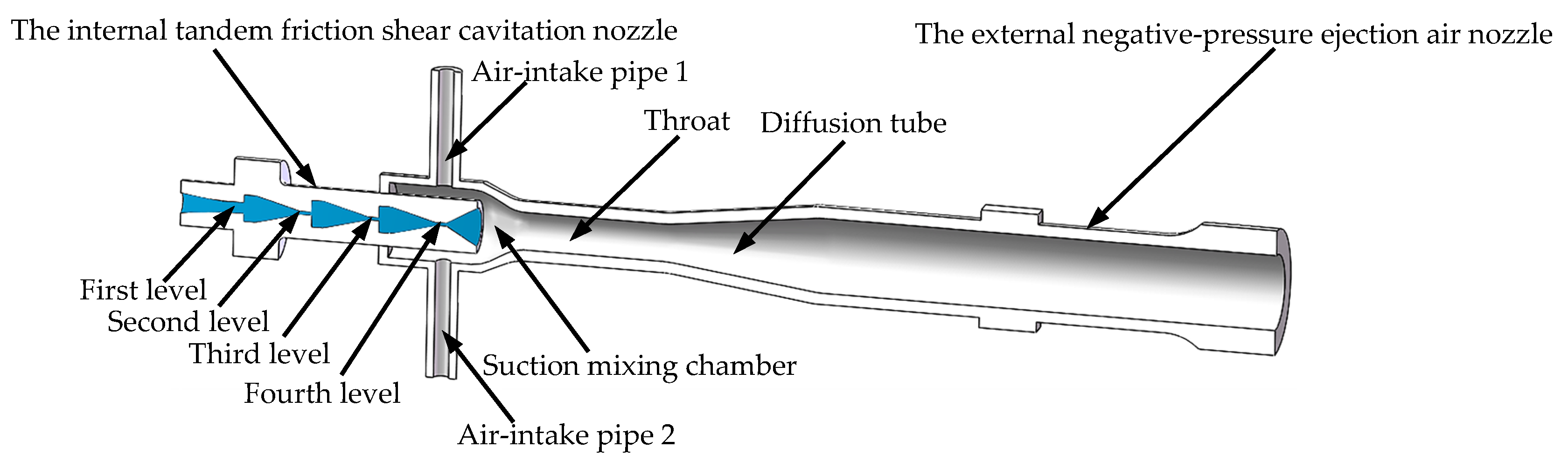
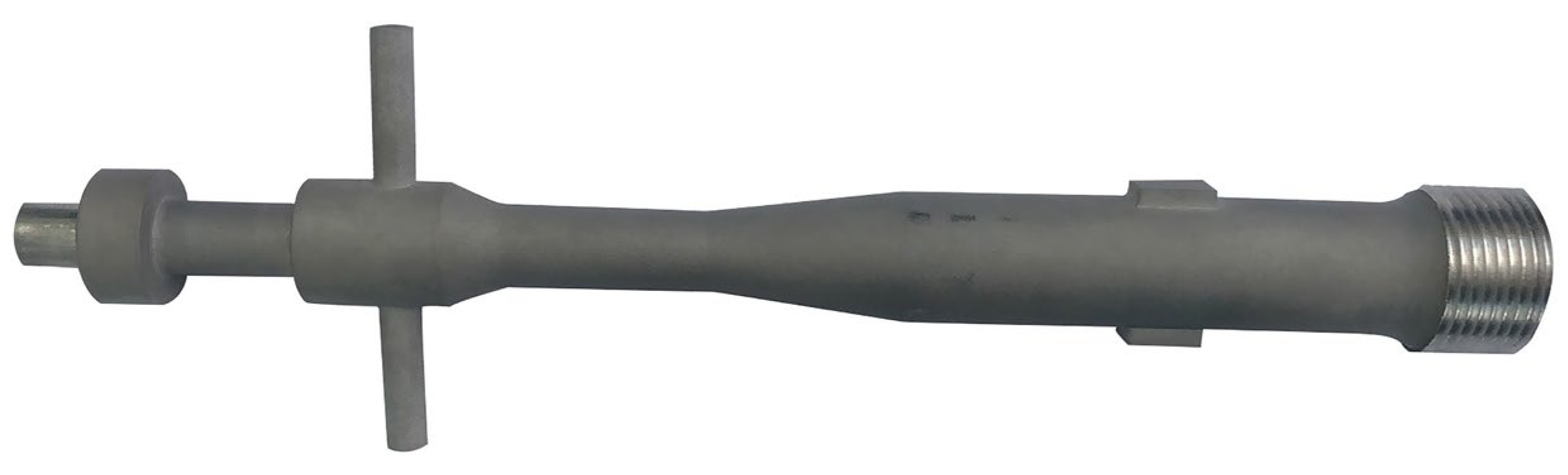
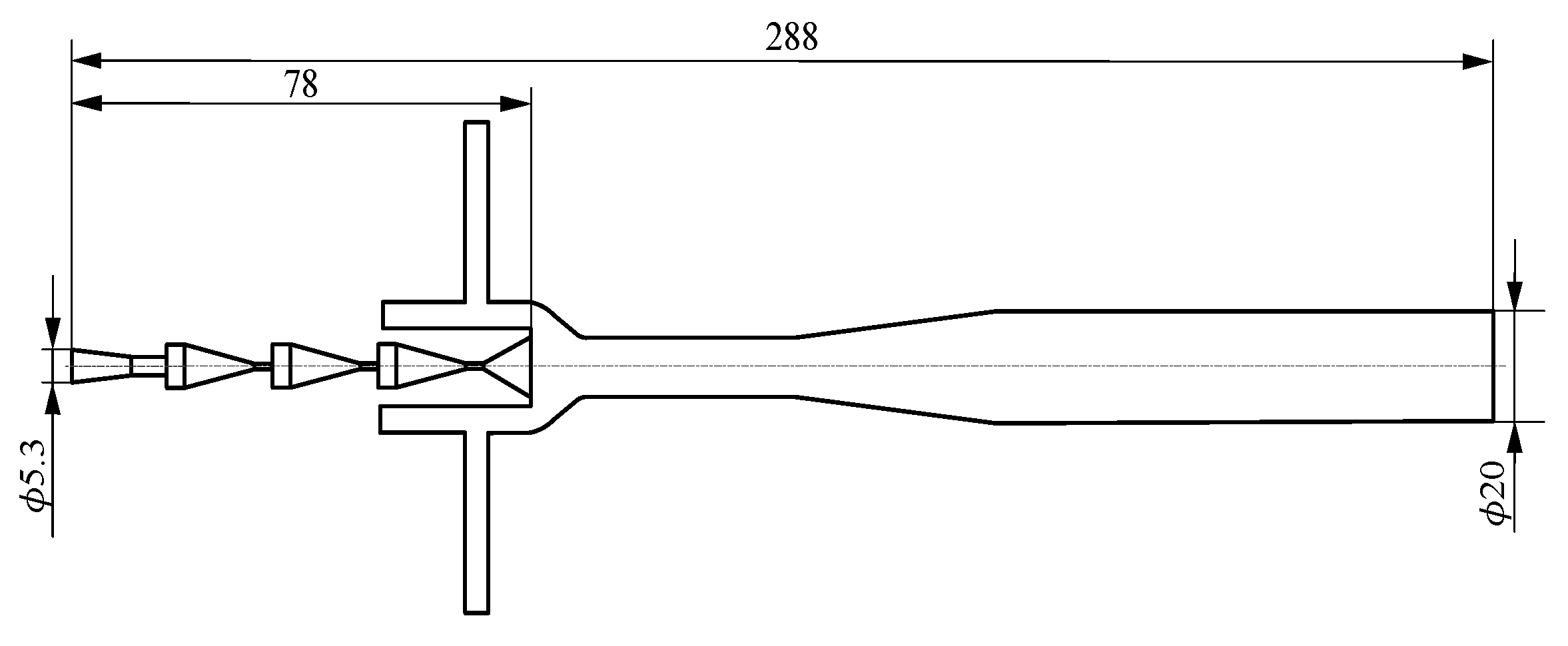
2.2.1. Overall Structure

Figure 1 illustrates the schematic configuration of the homemade double-nozzle jet micro-bubble generator. As depicted in Figure 1, the homemade double-nozzle jet micro-bubble generator consists of two parts: an internal tandem friction shear cavitation nozzle and an external negative-pressure-induced air nozzle. The internal tandem friction shear cavitation nozzle consists of four levels of nozzles: the first level for the cone-convergence-type nozzle, the second and third levels for the rectangular convergence of the flat friction nozzle, and the fourth level for the friction shear cavitation nozzle. The external negative-pressure ejection air nozzle consists of two air-intake pipes, a suction mixing chamber, throat, diffusion tube, and flow regulator tube. The physical diagram of the double-nozzle jet micro-bubble generator is shown in Figure 2.
The homemade double-nozzle jet micro-bubble generator has two functions. Firstly, the internal tandem friction shear cavitation nozzles make full use of the characteristics of the laminated structure of the flake graphite, the application of friction on the nozzle’s interior wall, and the dissociation of flake graphite through the cavitation of water jets to achieve the function of grinding. Secondly, the external negative-pressure-induced air nozzle can continuously and stably generate and release micro-bubbles of a suitable size and uniform distribution, which can fully collide and adhere with the dissociated flake graphite particles in the internal nozzle to form mineralized bubbles and realize the mineralization function.
The geometrical model of the inner fluid channel of the homemade double-nozzle jet micro-bubble generator is given in Figure 3. In Figure 3, for the internal tandem friction shear cavitation nozzles, the inlet diameter of the first-stage conical convergent nozzle is 5.3 mm, the flat section of the second third-stage rectangular convergent flat friction nozzles has a straight notch shape, and the diffusion section of the fourth-stage friction shear cavitation nozzle’s outlet diameter is 10 mm. The interior nozzles’ total length is 78 mm. For the external negative-pressure-induced air nozzle, the inlet diameter of both induced air tubes is 4 mm, and the suction mixing chamber’s diameter value is 20 mm. The double-nozzle jet micro-bubble’s total length value is 288 mm.

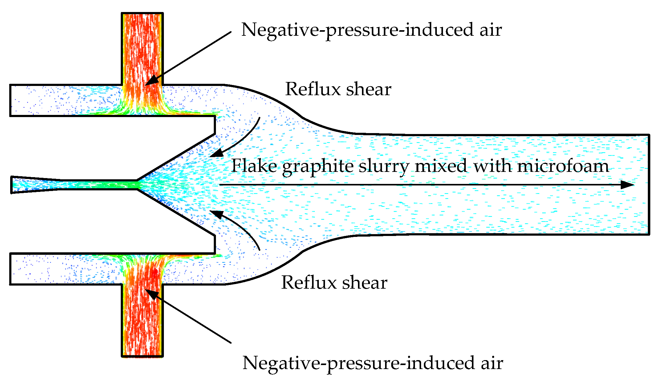
2.2.2. Internal Tandem Friction Shear Cavitation Nozzle Design

The internal tandem friction shear cavitation nozzle is made up of four sections. The first section of the cone convergent nozzle is designed according to the design guidelines of the cone convergent water nozzle and the actual demand to realize the acceleration of the flake graphite slurry. When the inlet pressure and flow rate of the first-stage cone-convergent nozzle are specific, the nozzle outlet diameter d is as follows [35]:
d = 4 Q π μ 2 p ρ
where Q represents the nozzle flow rate (m3/s); μ represents the flow coefficient, 0.80; p represents the inlet pressure (Pa); and ρ represents the density of flake graphite (kg/m3).
For the second- and third-level rectangular convergent flat friction nozzles, according to the characteristics of the laminated structure of flake graphite and the principle of grinding dynamics on the rectangular convergence of flat friction nozzle flat section of the straight groove design, enhance the friction shear effect of flake graphite particles and the nozzle channel wall, the dissociation of flake graphite. For the fourth level of the friction shear cavitation nozzle, due to the nozzle channel structure before the diffusion section with the second- and third-level nozzle structure being the same, the design method is the same as the second- and third-level nozzle, and for the fourth-level nozzle diffusion section, based on the theory of shear-type cavitation water jet design, the use of cavitation water jet bubbles produced by the collapse of the jet impact dissociates the flake graphite further. Simultaneously, the first-, second-, third-, and fourth-level nozzles are connected in a series to enhance the effect of the dissociation of the flake graphite, realizing the grinding function of the double-nozzle jet micro-bubble generator.

2.2.3. External Negative-Pressure-Induced Air Nozzle Design

The external negative-pressure-induced air nozzle is designed based on the jet pump and bubble generator principles. According to the exit diameter of the diffusion section of the fourth-stage nozzle of the internal tandem friction shear cavitation nozzle and taking into account that the solid-phase flake graphite particles should be in suspension during the conveying process, it is required that the mixed triple-phase flow velocity is not less than the critical velocity in the tube. Therefore, the diameter of the suction mixing chamber can be determined.
The external negative-pressure-induced air nozzle adopts a long throat design to enhance the likelihood of the colliding and adhesion of flake graphite particles and micro-bubbles and strengthen the mineralization effect. The throat’s diameter dh according to the empirical formula for jet pumps is as follows [36,37]:
d h = d ε m
m = 0.981 p c p atm + 1
where ε is the throat shrinkage coefficient (0.6~0.72); m is the optimal area ratio of the throat and inner nozzle outlet section; pc is the external negative-pressure-induced air nozzle outlet pressure (Pa); and patm is the atmospheric pressure (Pa).
The optimal throat length L is as follows [38]:
L = ( 7 . 77 + 2 . 42 m ) d h
The external negative-pressure-induced air nozzle is designed with a diffusion tube cone angle of 14°, and given the diffusion tube outlet diameter, the diffusion tube length Ld is determined by the results of the laboratory tests in this project and by referring to the literature [37]:
L d = k ( d d d h )
where k is the diffusion angle coefficient, take 7~10; dd is the outlet inner diameter of the diffusion angle (mm); and dh is the diameter of the throat (mm), according to Equations (2) to (5). The throat diameter, throat length, and diffusion tube length can be calculated, respectively.

2.3. Calculation Method and Boundary Condition Setting

To determine the calculation method and boundary condition setting, a separation solver is applied to the air–water–flake graphite triple-phase flow field characteristics of the double-nozzle jet micro-bubble generator and the Eulerian multiphase flow model is selected. Moreover, the default first-order accuracy windward differential format is used, and the standardized k-ε model is selected for the turbulence model [39]. The convergence criterion for the numerical simulation is the residual R ≤ 10−6, the relaxation factors are all adopted as default values, and the pressure–velocity coupling approach employs the phase-coupled SIMPLE algorithm [40].
The inlet of the internal cavitation nozzle of the double-nozzle jet micro-bubble generator is set as the liquid-solid two-phase pressure inlet, and the two air inlets and nozzle outlets of the external air nozzle of the double-nozzle jet micro-bubble generator are set as the air-phase pressure inlet and the air–water–flake graphite triple-phase pressure outlet, respectively. The double-nozzle jet micro-bubble generator’s interior wall is slid without velocity, and a standard wall function is selected near the inner wall surface of the nozzle.

3. Mathematical Mode

3.1. Control Equations for the Three-Phase Flow of Air–Water–Flake Graphite

The double-nozzle jet micro-bubble generator’s internal field of flow is a hybrid triple-phase highly turbulent jet, with interpenetrations and interactions between air-phase, water-phase, and flake-graphite-phase media. The hybrid triple-phase media are all approximate to a continuous medium. Furthermore, the solid-phase flake graphite slurry in the mixed three-phase has a volume percentage of 30%, which is more than 10%. These conditions are suitable for the Eulerian multiphase flow model [41]. Therefore, the Eulerian model is chosen in this study to investigate the triple-phase flow characteristics of the air, water, and flake graphite phases.
(1)
The equations for the conservation of mass for air, water, and flake graphite are as follows [42]:
𝜕 𝜕 t α a ρ a + α a ρ a v a = 0
𝜕 𝜕 t α w ρ w + α w ρ w v w = 0
𝜕 𝜕 t α s ρ s + α s ρ s v s = 0
where t represents the time (s); αa represents the volume ratio occupied by the air phase (%); ρa represents the air density (kg/m3); va represents the air velocity (m/s); αw represents the volume ratio occupied by the water (%); ρw represents the water density (kg/m3); vw represents the water velocity (m/s); αs represents the volume ratio occupied by the flake graphite (%); ρs represents the flake graphite density (kg/m3); and vs. represents the flake graphite velocity (m/s).
(2)
The equations for the conservation of momentum for air, water, and flake graphite are as follows [42]:
𝜕 𝜕 t α a ρ a v a + α a ρ a v a v a = α a p α a τ a + α a ρ a g + M i , a
𝜕 𝜕 t α w ρ w v w + α w ρ w v w v w = α w p α w τ w + α w ρ w g + M i , w
𝜕 𝜕 t α s ρ s v s + α s ρ s v s v s = α s p α s τ s + α s ρ s g + M i , s
where p represents the working pressure (Pa); τa represents the air shear stress (Pa); g represents the acceleration of gravity (m/s2); Mi,a represents the air-phase interphase force (N); τw represents the water-phase shear stress (Pa); Mi,w represents the water-phase interphase force (N); τs represents the flake-graphite-phase shear stress (Pa); and Mi,s represents the flake-graphite-phase interphase force (N).
The shear stresses τa, τw, and τs in Equations (9) to (11) for air, water, and flake graphite are as follows [43]:
τ a = α a μ a v a + v a T + α a λ a 2 3 v a v a I
τ w = α w μ w v w + v w T + α w λ w 2 3 v w v w I
τ s = α s μ s v s + v s T + α s λ s 2 3 v s v s I
where μa represents the air shear viscosity (Pa·s); λa represents the air bulk viscosity (Pa·s); μw represents the water shear viscosity (Pa·s); λw represents the water bulk viscosity (Pa·s); μs represents the flake graphite shear viscosity (Pa·s); λs represents the flake graphite bulk viscosity (Pa·s); and I represents the unit tensor.
(3)
Interphase forces of air, water, and flake graphite
In the air–water–flake graphite Eulerian triple-phase flow model, as a result of the phases’ different velocities, a velocity difference occurs between the phases so that interaction forces are generated between the phases, and momentum exchange is induced between the phases. To study the interphase forces between the three phases, it is now expected to take the interaction between two phases into account first and then analyze the impact of the presence of the third phase on the interplay between the other two phases to establish the interphase force equation for the coupling of the air–liquid–solid three phases. Therefore, this study is divided into air phase–water phase, water phase–flake graphite phase, and air phase–flake graphite phase to establish the interphase force equations.
 ①
Interphase forces in the air phase–water phase
The gas–liquid added mass force is caused by the acceleration difference between the water and air phases in the internal flow field of the double-nozzle jet micro-bubble generator. When the bubble accelerates, part of the fluid in the trailing vortex accelerates to increase its resistance, equivalent to increasing the bubble mass. The gas–liquid additional mass force Fvm,a-w is as follows [43]:
F vm , a - w = α a ρ w C M 𝜕 𝜕 t v w v a
where CM represents the additional mass force coefficient, which is taken to be 0.5 by default.
There are traction forces between air and water, and the Schiller–Naumann traction model can better describe air–liquid traction, which is Fdrag,a-w as follows [43,44,45]:
F drag , a - w = C D v w v a
C D = 24 ( 1 + 0 . 15 Re 0 . 687 ) / Re Re < 1000 0.44 Re 1000
where CD represents the gas–liquid traction coefficient, and Re represents the Reynolds number.
 ②
Interphase forces in the water phase–flake graphite phase
In the internal flow field of the double-nozzle jet micro-bubble generator, the trailing force between liquid and solid is minimal, and due to the small diameter of the flake graphite mineral particles, which has a robust flow-following property, the interphase force of the water phase–flake graphite phase in this environment can be neglected as a trailing force; only the shear lift of the water phase–flake graphite phase will be examined, and the liquid–solid shear lift Flift,w-s is as follows [43]:
F lift , w s = α w ρ s C L v s v w × v s
 ③
Interphase forces in the air phase–flake graphite phase
The force between the air phase–flake graphite phase in the inner flow field of the double-nozzle jet micro-bubble generator is mainly a trailing force generated due to the velocity gradient between the air bubbles and the flake graphite particles. This air–solid trailing force Fdrag,a-s is as follows [43,46]:
F drag , a - s = 3 4 C D α s α a ρ a v a v s d s α a 2.65
C D = 24 α s Re s 1 + 0 . 15 α s Re s 0 . 687 0 . 44 Re s < 1000 Re s 1000
Re s = ρ a d s v s v a μ a
where CD represents the gas–solid tracer coefficient, Res represents the gas–solid relative Reynolds number, and ds represents the flake graphite particles’ diameter (mm).

3.2. Turbulence Model

The double-nozzle jet micro-bubble generator’s inner flow field in this study belongs to the complex gas–liquid–solid three-phase turbulent suspension flow, which contains multifactorial physical processes such as turbulent jets, particle collisions, jet swirling suction, turbulent mixing, etc. At the same time, a high Reynolds number exists in the multiphase flow, so the standardized k-ε model for computing is selected as the turbulence model. This turbulence model contains two basic equations, the transport equations for turbulent kinetic energy k and dissipation rate ε [47]:
𝜕 𝜕 t ρ k + 𝜕 𝜕 x i ρ ku i = 𝜕 𝜕 x j μ + μ t σ k 𝜕 k 𝜕 x j + G k + G b ρ ε Y M
where μ represents the kinetic viscosity coefficient (Pa·s); μt represents the turbulent viscosity (Pa·s); σk represents the turbulent Platt’s number of turbulent kinetic energy; Gk represents the turbulent kinetic energy produced by the average velocity gradient; Gb represents the turbulent kinetic energy generated by the buoyancy force; and YM represents the contribution of pulsating expansion to the total dissipation rate in compressible turbulence.
𝜕 𝜕 t ρ ε + 𝜕 𝜕 x i ρ ε u i = 𝜕 𝜕 x i μ + μ t σ ε 𝜕 ε 𝜕 x j + C 1 ε ε k G k + C 3 ε G b C 2 ε ρ ε 2 k ε
where σɛ represents the turbulent Prandtl number of the dissipation rate; and C, C, and C are the experimentally measured constant coefficients. For numerical simulations, C = 1.44, C = 1.92, σk = 1.0, and σɛ = 1.3.

4. Simulation Results and Discussion

4.1. Finite Element Model

This study applies Solidworks to establish a geometric model of the flow field inside the double-nozzle jet micro-bubble generator. ICEM is used to perform tetrahedral unstructured meshing on the model. For the internal tandem friction shear cavitation nozzle rectangular convergence flat section and the external negative-pressure-induced air nozzle throat and other turbulence intensity regions for local encryption, this is to enhance the precision of calculations. Figure 4 depicts the finite element model of the double-nozzle jet micro-bubble generator.

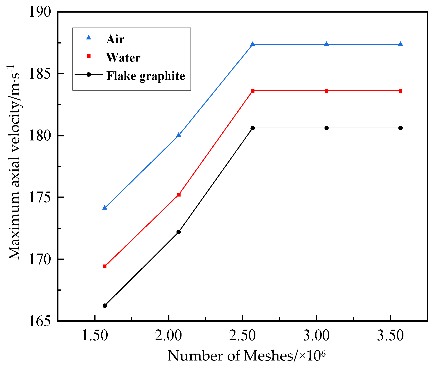
4.2. Mesh-Independence Test

A high-quality mesh is critical to the impact of computational results. In practical fluid dynamics computational applications, it is necessary to find the threshold value to reach mesh irrelevance [48]. Mesh-independence verification is a common method to solve this problem, and the most reasonable meshing scheme is selected based on the computational accuracy of numerical simulations with different numbers of meshes [49]. This study examines the mesh independence of the maximal axis velocity of the air–water–flake graphite triple-phase flow field under the inlet pressure of 45 MPa for five different grid number conditions, and the results of the simulation calculations after reaching the steady state can be seen in Table 1.
The maximal axis velocity variation curves of the air–water–flake graphite triple-phase flow field for five different mesh numbers are given in Figure 5. According to Figure 5 and Table 1 when the number of meshes is less than 2,568,291, the numerical simulation values of the maximal axis velocity of the water–air–flake graphite triple-phase flow field have a significant difference; when the number of meshes is greater than or equal to 2,568,291, the numerical simulation values of the maximal axis velocity of the air–water–flake graphite triple-phase flow field have a minimal difference. Therefore, considering the computational efficiency and precision of the simulation, it is determined that the number of meshes is 2,568,291 to meet the requirement of mesh number irrelevance, and the corresponding number of nodes is 356,453.

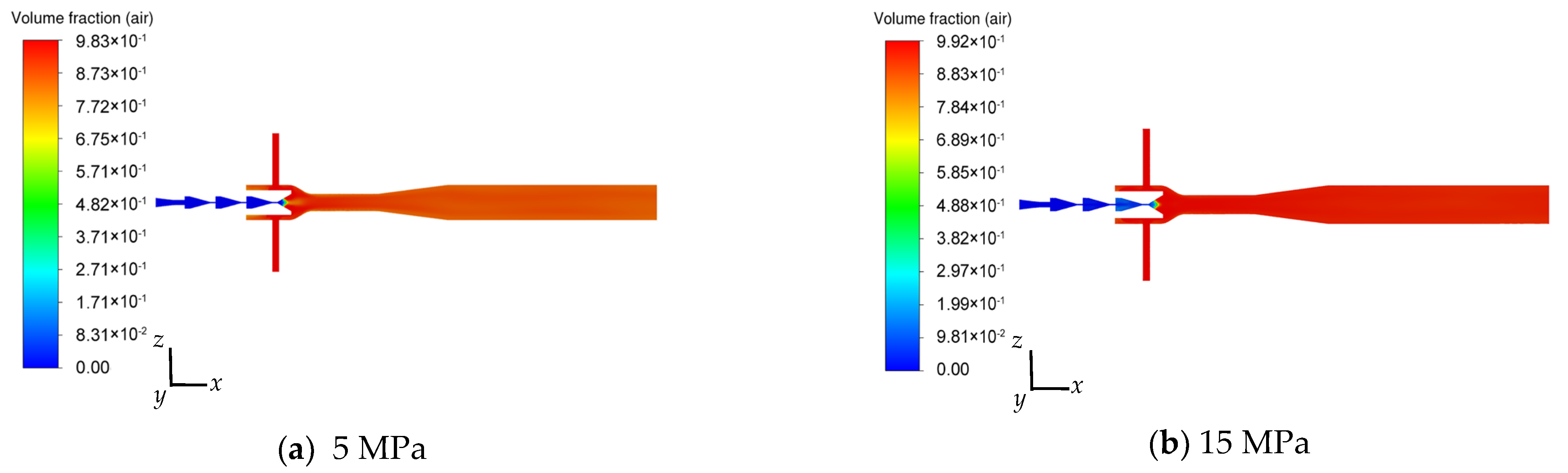
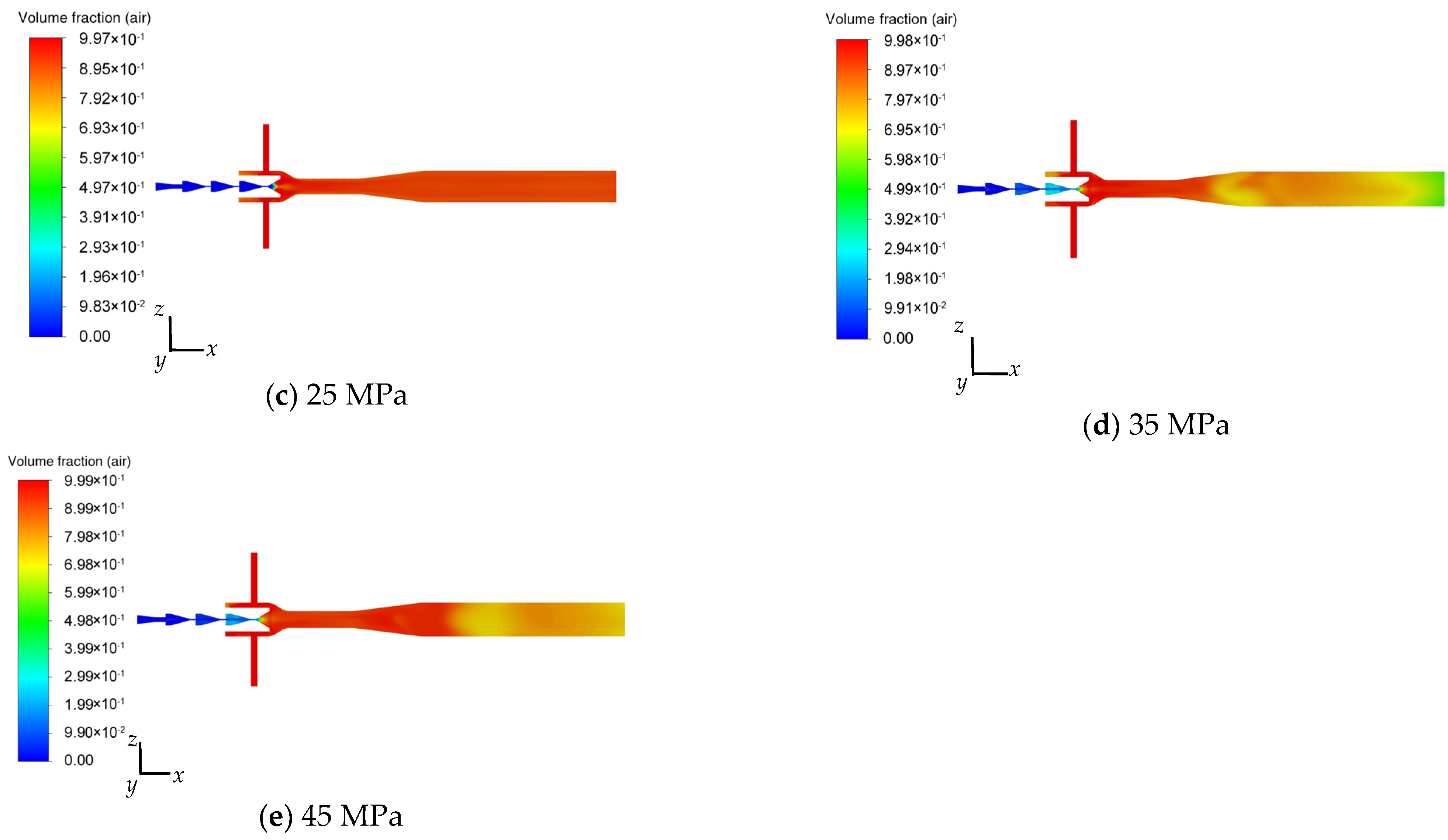
4.3. Effect of Inlet Pressure on the Air Flow Field

With different inlet pressures of the double-nozzle jet micro-bubble generator, the flake graphite slurry is ejected from the internal nozzles at different speeds, with varying air intake and air-phase volume fractions. Figure 6 depicts a cloud chart of the air volume fraction distribution when the inlet pressure of the micro-bubble generator is 5, 15, 25, 35, and 45 MPa, respectively. According to the data demonstrated in Figure 6, the air volume fraction in the flow field of the double-nozzle jet micro-bubble generator is more significant than 98% under different inlet pressures, and it is approximately uniformly distributed in the steady flow tube. Specifically, when the flake graphite slurry is ejected from the internal series friction shear cavitation nozzle at high speed, the cavitation nozzle’s exit point experiences negative pressure due to the high-speed flow of the slurry. The ejection generates a negative pressure, causing the outside air to be drawn into the mixing chamber via the entrance of the double-input pipe of the external air nozzle.
The air entering the mixing chamber is fully collided and sheared by the graphite slurry sprayed out from the cavitation nozzle at high speed, and split into countless tiny bubbles to form an air–water–flake graphite triple-phase flow into the throat and then into the diffusion tube and the steady flow tube; in the throat, diffusion tube, and the continuous flow tube, due to the fluid role of the high turbulence intensity of the air–water–flake graphite triple-phase media to enhance further mixing to promote a more even distribution of bubbles, the bubbles in the steady flow tube show an approximate uniform distribution. The results obtained by Li et al. [25] align with the present study, as they found that the dual-intake tube configuration yields a more homogeneous dispersion of bubbles compared to the jet micro-bubble generator with a single-intake tube configuration.
At the same time, as seen in Figure 6, the negative-pressure ejection effect of the flake graphite slurry from the cavitation nozzle at high speed is directly proportional to the inlet pressure. As the inlet pressure increases, a greater influx of air results in a more substantial air-phase volume percentage. When the inlet pressure is 5, 15, 25, 35, and 45 MPa, the resulting air-phase volume fraction is 98.3%, 99.2%, 99.7%, 99.8%, and 99.9%, respectively, which indicates that the homemade double-nozzle jet micro-bubble generator has good self-absorption performance. Sufficient air intake by the high-speed flow of flake graphite slurry fully collision shears into tiny bubbles, which is conducive to the mineralization of flake graphite, to achieve the mineralization function of the double-nozzle jet micro-bubble generator.
Figure 6 also shows a significant air-phase volume percentage close to the wall of the diffusion portion of the internal tandem friction shear cavitation nozzle. This is because the flake graphite slurry is ejected from the friction portion of the fourth-stage nozzle of the internal tandem friction shear cavitation nozzle into the diffusion portion. In the diffusion portion, the slurry’s axial velocity in the radial direction exhibits a substantial velocity gradient. This gradient is further amplified in the shear layer, producing a notable structural vortex ring. The pressure in the center of the vortex ring is lower than the saturated vapor pressure of the water, forming numerous bubbles due to cavitation. This finding aligns with the result drawn by Yasunari et al. [50], which suggests that the primary site for vacuole formation inside the depressurized nozzle is the low-pressure area of the flow channel, as seen by a high-speed camera.
Figure 7 gives the vector diagram of air flow field velocity distribution in the mixing chamber of the external negative-pressure-induced air nozzle at the inlet pressure of 25 MPa of the double-nozzle jet micro-bubble generator. As seen in Figure 7, there is obvious air reflux near the wall of the diffusion section of the internal tandem friction shear cavitation nozzle; the refluxed air is superimposed with the air bubbles generated during the cavitation of the diffusion section and under the hostage effect of the slurry to form an air–water–flake graphite triple-phase flow to the downstream throat, diffusion tube up to the stabilizer tube, and the bubbles exhibit a uniform spread in the flow stabilizer tube. Therefore, the vacuoles generated by cavitation are an essential part of the gas volume percentage in the homemade double-nozzle jet micro-bubble generator. This is in agreement with Deng [19], who found that the cavitation effect of the micro-bubble generator assumes a crucial function in micro-bubble production and the mineralization process during mineral flotation when simulated.

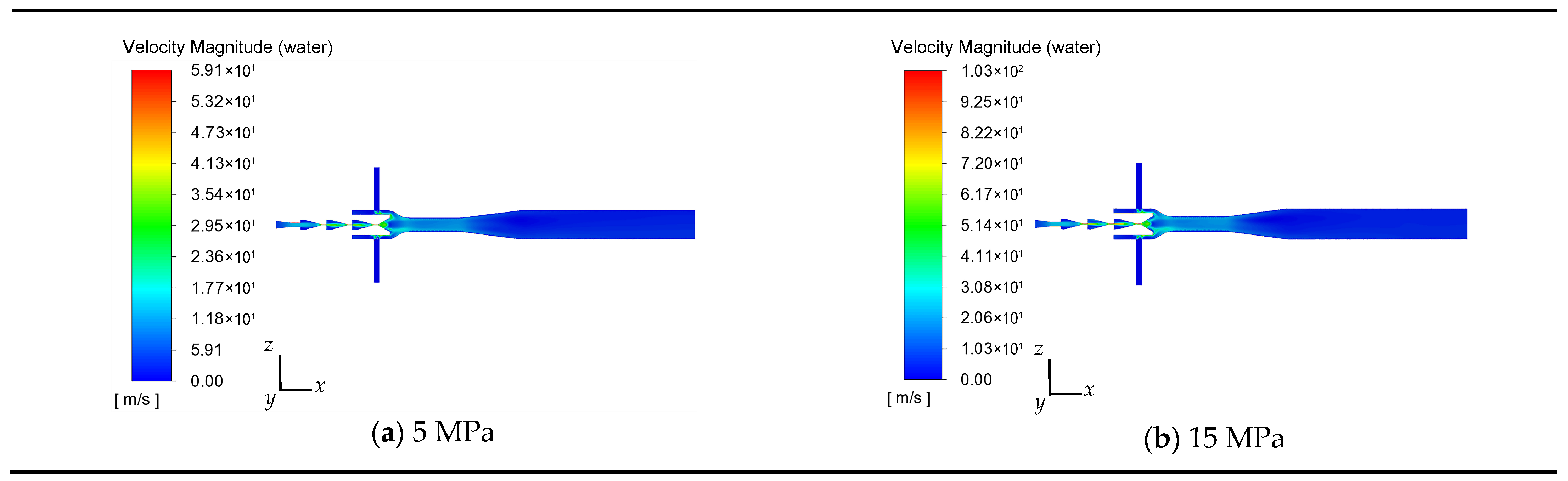
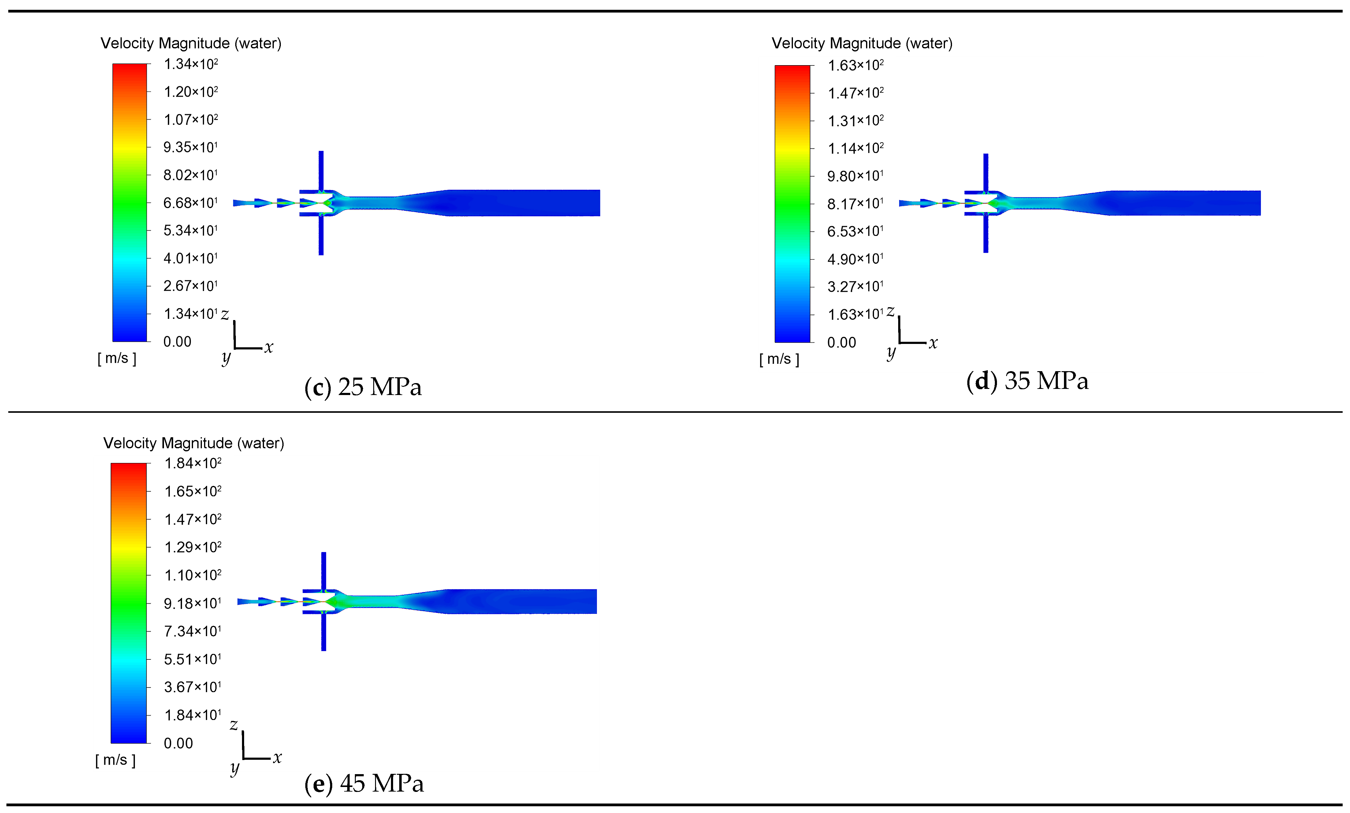
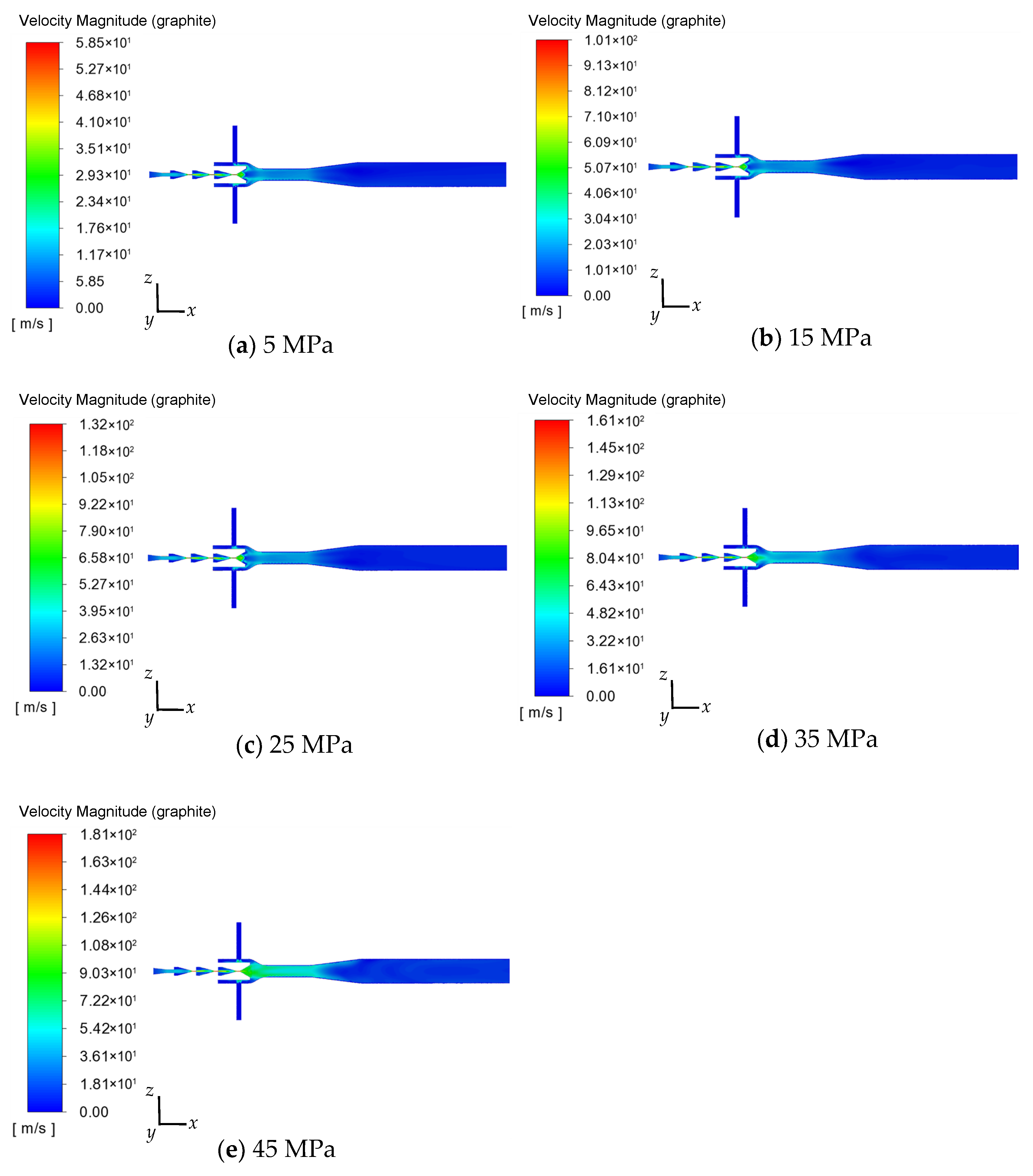
4.4. Effect of Inlet Pressure on the Flow Field of Water and the Flow Field of Flake Graphite

As shown in Figure 8, the axis velocity of the water of the double-nozzle jet micro-bubble generator shows a symmetrical distribution up and down at inlet pressures of 5, 15, 25, 35, and 45 MPa, respectively, and the maximum axis velocity of the water is proportional to the inlet pressure. Specifically, the liquid-phase water in the slurry enters the slurry through the inlet of the tandem friction shear cavitation nozzles inside the double-nozzle jet micro-bubble generator. After entering the water first through the internal nozzle of the first stage of the nozzle, the first stage of the nozzle convergence section of the axis velocity of the water increases rapidly. In the cylindrical section, the axis velocity basically remains unchanged; this is due to the cylindrical section of the entrance position. In the inertial effect of the water, the water can only exhibit a gradual, smooth, and continuous bending of the water flow so that the fluid cross-section of the contraction is of a certain degree. Then, into the second level of the rectangular convergence flat friction nozzle, because the second level of the nozzle entrance in the flow channel cross-section expands and then gradually contracts, the axis velocity of the water in the second level of the nozzle first decreases and then gradually increases in the friction section of the axial velocity, which remains unchanged. After entering the third level of the rectangular convergence flat friction nozzle, because the third level of the nozzle structure is the same as the second-level nozzle, the axis velocity of the water in the third level of the rule of change and the second level of the rule of change of is the same. Finally, the water enters the fourth level of friction shear cavitation nozzle because the fourth level of nozzle channel structure in the before diffusion section with the second level and the third level of nozzle structure, so in this part of the channel in the axis velocity change rule of the water with the second level, the third level of the axis velocity change rule of the nozzle is the same; in the nozzle diffusion section of the axis velocity of the water is rapidly decreasing.
The water from the fourth-stage nozzle in the mixing chamber of the external air nozzle is strongly mixed with the air introduced under negative pressure, and then flows into the throat through the mixing chamber contraction section to realize the second acceleration, and then flows through the downstream diffusion section and the steady flow tube out of the double-nozzle jet micro-bubble generator. The axial velocity is basically kept unchanged in the throat and decreases because of the gradual expansion of the cross-section in the diffusion tube, which basically keeps the axial velocity constant in the steady flow tube. The maximum axial velocities of the water are 59.1, 103.0, 134.0, 163.0, and 184.0 m/s when the inlet pressures are 5, 15, 25, 35, and 45 MPa, respectively.
As shown in Figure 9, the change rule and distribution of axis velocity of the flake graphite of the double-nozzle jet micro-bubble generator is the same as that of the water when the inlet pressures are 5, 15, 25, 35, and 45 MPa, respectively. The maximum axis velocity of the flake graphite is proportional to the inlet pressure. The maximum axis velocities of the flake graphite are 58.5, 101.0, 132.0, 161.0, and 181.0 m/s when the inlet pressures are 5, 15, 25, 35, and 45 MPa, respectively.
It should be emphasized that first, under the same inlet pressure conditions, the maximum axis velocity of the flake graphite is slightly smaller than the maximum axis velocity of the water. This is due to the density of flake graphite being 2.1 times the density of water, and the inertia of flake graphite is greater than the inertia of water in the water–flake graphite liquid–solid two-phase flow and air–water–flake graphite gas–liquid–solid three-phase flow process. Secondly, the slurry composed of water and flake graphite is sprayed from the internal nozzle at high speed into the suction mixing chamber of the external nozzle, which is strongly combined with the air inhaled from the double-inlet pipe to form the air–water–flake graphite triple-phase flow field, and then flows into the throat through the suction mixing chamber contraction tube to realize the secondary acceleration and the stabilized flow adjustment of the three-phase fluid flow in the throat. Third, the air–water–flake graphite triple-phase fluid enters the downstream diffusion tube after stabilizing the flow through the throat. The axis velocity of the air–water–flake graphite triple-phase fluid in the diffusion tube has a large radial velocity gradient. A sizeable structural vortex ring is formed by the velocity gradient in the shear layer. The vortex ring generates a region of reduced pressure at its central region, resulting in the roll suction effect on the surrounding fluid. The air has a significantly lower density compared to the water and the flake graphite, so the air bubbles are first rolled into the vortex ring, realizing intense collisions between bubbles, crushing and prolonging the residence time of bubbles. This coincides with the findings of Huang et al. [51] that the reflux coiling suction impact observed in the diffusion zone of the micro-bubble generator can effectively enhance the interaction between bubbles while prolonging the bubble residence time and significantly increasing the collision probability. Fourthly, the flake graphite particles in the friction region of level two to level four of the internal nozzle and the convergence region of level one to level four of the nozzles all generate strong friction and shear effects between the flake graphite particles and the interior portion of the nozzle to dissociate the flake graphite, and at the same time, the cavitation effect generated in the diffusion section of the fourth-stage nozzles of the internal nozzles also dissociates the flake graphite. This comprehensive dissociation of flake graphite realizes the micro-bubble generator’s grinding function.
After studying the law of the inlet pressure on the triple-phase velocity flow field, the influence of the inlet pressure on the turbulence intensity of the law was further studied. Figure 10 provides an example of the turbulence kinetic energy distribution of the double-nozzle jet micro-bubble generator inlet pressure of 15 MPa in a cloud diagram. As can be seen from Figure 10, the turbulent kinetic energy reaches its maximum at the joint of the double air-intake pipe and the mixing chamber, and the maximum value is generated due to the low-speed airflow being sucked, collided, and sheared by the high-speed jet slurry. The high turbulence intensity is conducive to promoting the air–water–flake graphite mixing, thus improving the shear effect on the airflow introduced by the negative pressure, which is conducive to the realization of the generation and uniform distribution of micro-bubbles.

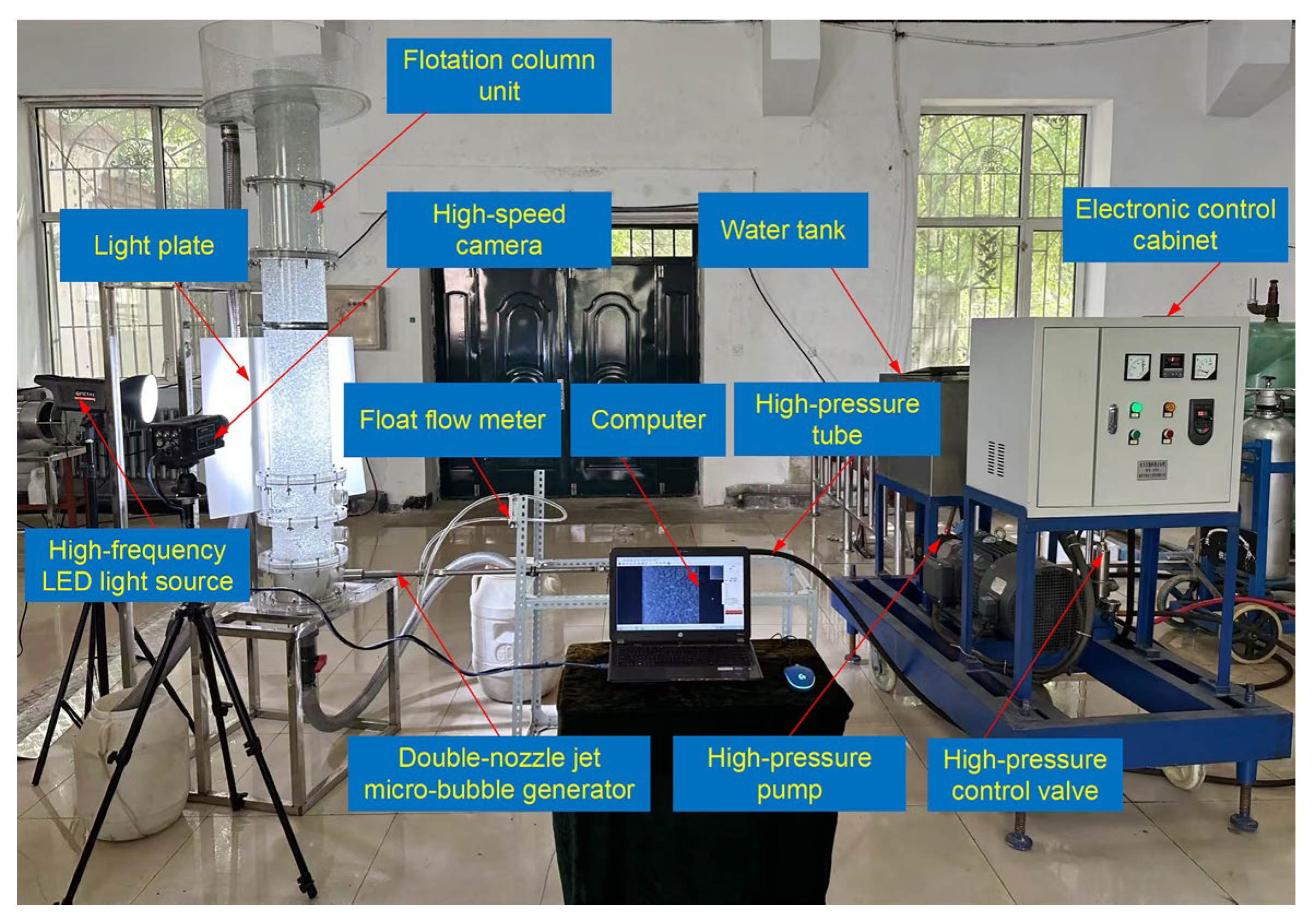
4.5. Experimental Validation

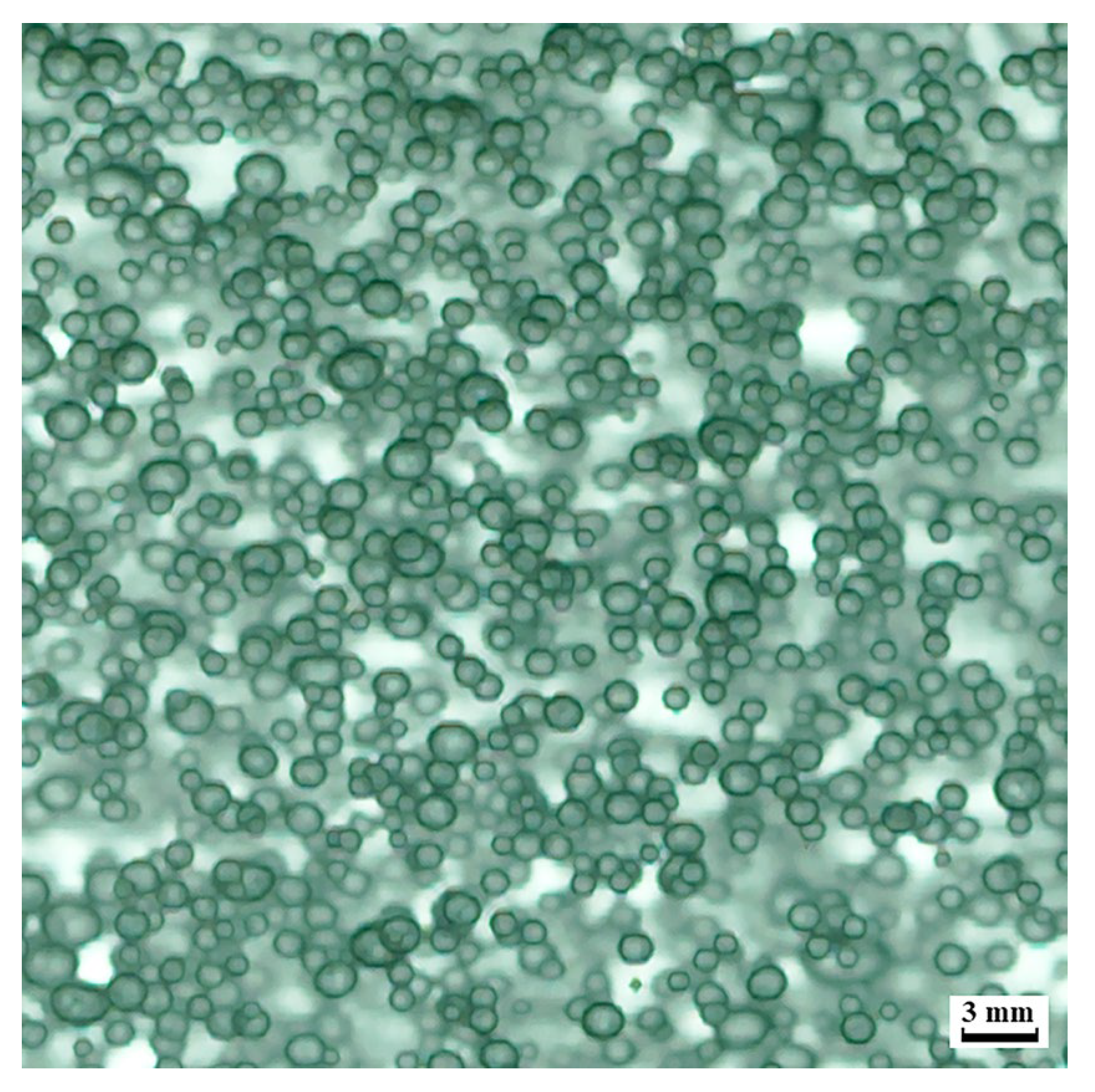
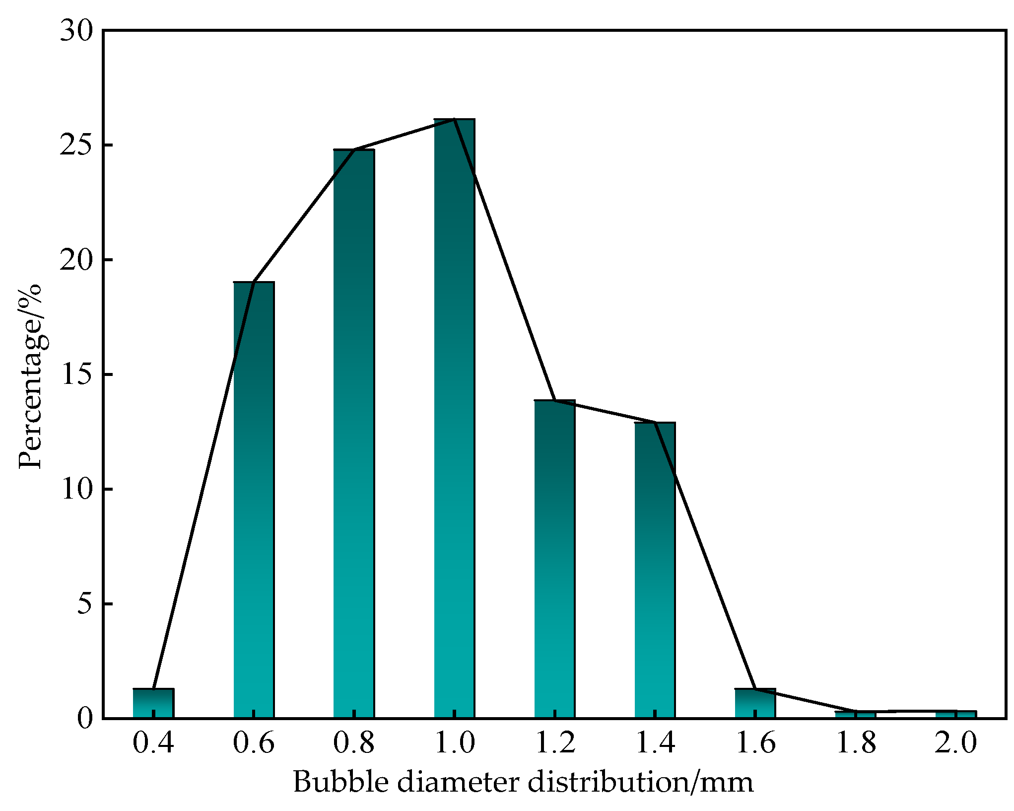
4.5.1. Bubble Cluster Visualization Test

The bubble visualization test system for the homemade double-nozzle jet micro-bubble generator is shown in Figure 11. As seen in Figure 11, the system mainly consists of a water tank, a high-pressure pump, a high-pressure control valve, a high-pressure tube, a double-nozzle jet micro-bubble generator, a float flow meter, a flotation column unit, a high-frequency LED light source, a light plate, a high-speed camera, and a computer PC port. During the test, the inlet pressure of the double-nozzle jet micro-bubble generator was 15 MPa, and the air inlet of the float flow meter was 20 LPM. The high-speed camera captured a photo of the bubble group morphology generated by the air–water two-phase fluid injected into the capture area of the flotation column unit through the double-nozzle jet micro-bubble generator.
The working principle of the double-nozzle jet micro-bubble generator is that the high-pressure water generated by the high-pressure pump enters the double-nozzle jet micro-bubble generator through the high-pressure tube into the internal tandem friction shear cavitation nozzle and is then sprayed out at the fourth cavitation nozzle at a very high speed. The negative-pressure ejection of high-speed jets causes the outside air to enter into the double air-intake pipe through the float flow meter, and at the inlet of the double air-intake pipe, a relatively uniform flow rate is sucked into the mixing chamber of the external negative-pressure ejection air nozzle of the double-nozzle jet micro-bubble generator. Near the outlet of the fourth-stage cavitation nozzle, there is a significant velocity difference between the high-speed jet and the airflow introduced by the negative pressure. The low-speed airflow is carried by the high-speed jet and crushed into countless tiny bubbles. The contraction section of the throat promotes the gas–liquid two-phase flow to contact and mix further fully, and then it is injected into the flotation column device through the outlet of the double-nozzle jet micro-bubble generator. The bubble group morphology photos of the double-nozzle jet micro-bubble generator taken by the high-speed camera are shown in Figure 12. It can be seen from Figure 12 that under the combined action of the internal tandem friction shear cavitation nozzle diffusion section and the external negative-pressure ejection air nozzle steady flow tube, the jet produced a dense and uniform bubble group. The area percentage, aspect ratio, and bubble spacing of the bubble group were good, indicating that the self-suction performance of the homemade double-nozzle jet micro-bubble generator was good. The sufficient air intake was fully collided and sheared into tiny bubbles by the high-speed jet, which could produce a bubble group with uniform dispersion, which verified the accuracy of the numerical simulation results.
Since the bubble size determines the surface area of the bubble in contact with the flake graphite particles, it plays a crucial role in the flotation flake graphite environment. Therefore, to evaluate the bubble size generated by the double-nozzle jet micro-bubble generator, Image-Pro Plus software was used to obtain the average bubble size, and the bubble size distribution graph was plotted, to visually characterize the diameter of micro-bubbles generated by the double-nozzle jet micro-bubble generator. The histogram of bubble diameter distribution is shown in Figure 13, from which it can be seen that the bubble size distribution is unimodal, and the average size of bubbles less than or equal to 1 mm accounted for 71.26% of the total number of bubbles, indicating that the bubble size distribution is centralized, presenting a uniform bubble group dispersion distribution state and a good specific surface area, which is conducive to the realization of the sorting of the flake graphite.

4.5.2. Integration Test of Flake Graphite Grinding and Floating

The integrated test system of the double-nozzle jet micro-bubble generator on flake graphite grinding and floating is shown in Figure 14. As can be seen in Figure 14, the system mainly consists of a water tank, high-pressure pump, electronic control cabinet, high-pressure pipe, high-pressure control valve, flake graphite slurry tank, double-nozzle jet micro-bubble generator, a float flow meter, flotation column unit, concentrate collection bucket, and tailings collection bucket and other components. The test process is as follows: a high-pressure pump to pressurize the water to the working pressure of 15 MPa, pressurized high-pressure water into the flake graphite slurry tank to complete the mixing with the flake graphite after the flow to the double-nozzle jet micro-bubble generator, the internal tandem friction shear cavitation nozzle for multistage dissociation of the flake graphite to achieve the function of grinding, while at the same time, a graphite slurry high-speed flow of the negative pressure generated by the air sucked into the external negative-pressure ejection air nozzle inside the mixing chamber, air from the high-speed flow of the graphite slurry impact and shear action to form tiny bubbles, and gas–liquid two-phase accumulation to form a high gas capacity, conducive to the formation of mineralization bubbling and mineralization function. The flake graphite slurry after grinding and mineralization is discharged to the flotation column device through the double-nozzle jet micro-bubble generator, the graphite concentrate and tailings are separated in the flotation column device, the graphite concentrate is collected in the concentrate tank at the upper end of the flotation column device, and the tailings are discharged from the tailings tank at the lower end of the flotation column device, which realizes the integration of grinding and flotation in the processing of flake graphite.
In this study, the fixed carbon content of flake graphite was used as an evaluation index. By measuring the fixed carbon content of flake graphite samples before and after the test, the grinding and mineralization effect of flake graphite by the double-nozzle jet micro-bubble generator was obtained. Since the test sample is the first stage of the beneficiation product of Jixi Liumao graphite ore, the fixed carbon content of the flake graphite sample after the test was compared with the fixed carbon content of the secondary and tertiary stage of the beneficiation products in the actual industrial beneficiation process of Jixi Liumao graphite, and the optimization effect of the double-nozzle jet micro-bubble generator on shortening the flake graphite beneficiation process was evaluated.
In order to ensure the accuracy of the measurement results of the fixed carbon content of flake graphite, the flake graphite samples before the grinding and flotation integration test and the flake graphite concentrate samples after the grinding and flotation integration test were divided into two groups, with 1 g for each group. The fixed carbon content of each group of samples was determined by using the subtraction method, and the average value was calculated. The fixed carbon content of the flake graphite samples before the test and the flake graphite concentrate samples after the test were 49.11% and 80.70%, respectively. Moreover, the fixed carbon content of the concentrate samples after the test increased by 31.59%, indicating that the double-nozzle jet micro-bubble generator can effectively dissociate the vein stone impurities on the surface of flake graphite, and at the same time, the generator can realize the mineralization function of flake graphite, which greatly improves its grade. In addition, the fixed carbon content of the flake graphite concentrate samples after the grinding and flotation integration test was higher than the fixed carbon content of the secondary and tertiary stages of the beneficiation products of Jixi Liumao graphite ore. This result indicates that conducting the single grinding and flotation integration test on flake graphite by using the double-nozzle jet micro-bubble generator can replace the three beneficiation steps of primary grinding, secondary flotation, and secondary grinding in the actual beneficiation process; moreover, the generator can achieve the aim of shortening the actual conventional flake graphite beneficiation process.

5. Conclusions

In this study, a homemade double-nozzle jet micro-bubble generator was proposed to integrate the existing independent operations of conventional flake graphite grinding and mineralization into one process. The CFD method was used to solve the micro-bubble generator air–water–flake graphite triple-phase flow, and the results were compared with those from an existing jet micro-bubble generator to validate the reasonableness of the design of the homemade double-nozzle jet micro-bubble generator.
A positive correlation exists between the air-phase volume percentage and the inlet pressure produced by the double-nozzle jet micro-bubble generator. The air-phase volume percentage is approximately uniformly distributed in the stabilizer tube. The air-phase volume percentages produced by the micro-bubble generator are 98.3, 99.2, 99.7, 99.8, and 99.9% when the inlet pressures are 5, 15, 25, 35, and 45 MPa, respectively. This indicates a homemade double-nozzle jet micro-bubble generator has an excellent self-absorption performance to achieve the mineralization function.
The axis velocities of the water and the flake graphite inside the homemade double-nozzle jet micro-bubble generator were distributed symmetrically upward and downward, and both positively correlated with the inlet pressure for the same inlet pressure. The maximum axial velocity of the flake graphite was slightly smaller than that of the water. The flake graphite is dissociated under the combined effect of friction shear and cavitation in the internal nozzle to realize the grinding function.

Author Contributions

Conceptualization, X.D.; methodology, X.D. and C.G.; software, C.G.; validation, X.D. and C.G.; formal analysis, C.G.; investigation, X.D., C.G., D.P. and Y.J.; resources, X.D. and D.P.; data curation, C.G.; writing—original draft preparation, C.G.; writing—review and editing, X.D. and D.P.; visualization, C.G. and Y.J.; supervision, X.D.; project administration, X.D.; funding acquisition, X.D. All authors have read and agreed to the published version of the manuscript.

Funding

This research was supported by the National Natural Science Foundation of China (No. 52075151) and the Natural Science Foundation of Heilongjiang Province (No. LH2020E123).

Data Availability Statement

The data presented in this study are available on request from the corresponding author. As the data in this paper belongs to the National Natural Science Foundation of China, it involves related privacy and is not owned by individuals.

Conflicts of Interest

The authors declare no conflicts of interest.

References

  1. Bernard, A.; Khalil, N.; Ahmed, I.; McCalden, D.; Haelssig, J.; Macchi, A.; Duchesne, M. Gas fluidization of natural graphite flakes. Powder Technol. 2024, 431, 119097. [Google Scholar] [CrossRef]
  2. Sun, K.K.; Qiu, Y.S.; Zhang, L.Y. Preserving Flake Size in an African Flake Graphite Ore Beneficiation Using a Modified Grinding and Pre-Screening Process. Minerals 2017, 7, 115. [Google Scholar] [CrossRef]
  3. Al-Ani, T.; Leinonen, S.; Ahtola, T.; Salvador, D. High-Grade Flake Graphite Deposits in Metamorphic Schist Belt, Central Finland-Mineralogy and Beneficiation of Graphite for Lithium-Ion Battery Applications. Minerals 2020, 10, 680. [Google Scholar] [CrossRef]
  4. Vasumathi, N.; Sarjekar, A.; Chandrayan, H.; Chennakesavulu, K.; Reddy, G.R.; Kumar, T.V.V.; El-Gendy, N.S.; Gopalkrishna, S.J. A Mini Review on Flotation Techniques and Reagents Used in Graphite Beneficiation. Int. J. Chem. Eng. 2023, 2023, 1007689. [Google Scholar] [CrossRef]
  5. Srikant, S.S.; Rao, R.B. Preparation of High Purity Graphite using Comminution, Pressure Leaching and Flotation. J. Min. Environ. 2023, 14, 2461. [Google Scholar] [CrossRef]
  6. Peng, Z.M.; Li, D.S.; Fang, W.J.; Zhang, J.; Zhang, R.Y.; Qiu, Y.S.; Sun, K.K. Improved Flotation of Fine Flake Graphite Using a Modified Thickening Process. Separations 2023, 10, 275. [Google Scholar] [CrossRef]
  7. Ghosh, A.K. Literature quest and survey on graphite beneficiation through flotation. Renew. Sustain. Energy Rev. 2024, 189, 113980. [Google Scholar] [CrossRef]
  8. Gao, J.X.; Bu, X.N.; Dong, L.S.; Qiu, Y.S.; Xie, G.Y.; Chelgani, S.C. Natural Graphite Froth Flotation—An Overview. Miner. Process. Extr. Metall. Rev. 2024, 1–18. [Google Scholar] [CrossRef]
  9. Yoon, R.H. Microbubble flotation. Miner. Eng. 1993, 6, 619–630. [Google Scholar] [CrossRef]
  10. Lee, J.E.; Choi, W.S.; Lee, J.K. A study of the bubble properties in the column flotation system. Korean J. Chem. Eng. 2003, 20, 942–949. [Google Scholar] [CrossRef]
  11. Gui, X.H.; Liu, J.T.; Cao, Y.J.; Ding, Q.P. Research and Progress on the Structural Properties of Bubble Generators. Coal Prep. Technol. 2009, 2, 66–70+81. [Google Scholar] [CrossRef]
  12. Matiolo, E.; Couto, H.J.B.; Lima, N.; Silva, K.; de Freitas, A.S. Improving recovery of iron using column flotation of iron ore slimes. Miner. Eng. 2020, 158, 106608. [Google Scholar] [CrossRef]
  13. Tortorelli, J.P.; Craven, J.W.; Toguri, J.M.; Dobby, G.S.; Agar, G.E. The effect of external gas/slurry contact on the flotation of fine particles. Miner. Eng. 1997, 10, 1127–1138. [Google Scholar] [CrossRef]
  14. Shuai, Y.; Wang, X.Y.; Huang, Z.L.; Yang, Y.; Sun, J.Y.; Wang, J.D.; Yang, Y.R. Structural Design and Performance of a Jet-Impinging TypeMicrobubble Generator. Ind. Eng. Chem. Res. 2022, 61, 4445–4459. [Google Scholar] [CrossRef]
  15. Chen, W.Y.; Wang, J.B.; Jiang, N.; Zhao, B.; Wang, Z.D. Numerical simulation of gas-liquid two-phase jet flow in air-bubble generator. J. Cent. South Univ. Technol. 2008, 15, 140–144. [Google Scholar] [CrossRef]
  16. Wu, M.; Yuan, S.Y.; Song, H.Y.; Li, X.B. Micro-nano bubbles production using a swirling-type venturi bubble generator. Chem. Eng. Process.-Process Intensif. 2022, 170, 108697. [Google Scholar] [CrossRef]
  17. Sadatomi, M.; Kawahara, A.; Kano, K.; Ohtomo, A. Performance of a new micro-bubble generator with a spherical body in a flowing water tube. Exp. Therm. Fluid Sci. 2005, 29, 615–623. [Google Scholar] [CrossRef]
  18. Gordiychuk, A.; Svanera, M.; Benini, S.; Poesio, P. Size distribution and Sauter mean diameter of micro bubbles for a Venturi type bubble generator. Exp. Therm. Fluid Sci. 2016, 70, 51–60. [Google Scholar] [CrossRef]
  19. Deng, X.W.; Lv, B.; Cheng, G.; Lu, Y. Mechanism of micro/nano-bubble formation and cavitation effect on bubbles size distribution in flotation. Physicochem. Probl. Miner. Process. 2020, 56, 504–512. [Google Scholar] [CrossRef]
  20. Fujiwara, A.; Okamoto, K.; Hashiguchi, K.; Peixinho, J.; Takagi, S.; Matsumoto, Y.; ASME. Bubble breakup phenomena in a venturi tube. In Proceedings of the 5th Joint ASME/JSME Fluids Engineering Summer Conference, San Diego, CA, USA, 30 July–2 August 2007. [Google Scholar]
  21. Tsave, P.K.; Kostoglou, M.; Karapantsios, T.D.; Lazaridis, N.K. A Hybrid Device for Enhancing Flotation of Fine Particles by Combining Micro-Bubbles with Conventional Bubbles. Minerals 2021, 11, 561. [Google Scholar] [CrossRef]
  22. Fu, X.Z.; Niu, Z.; Lin, M.; Gao, Y.; Sun, W.; Yue, T. Strengthened Oxygen Oxidation of Ferrous Ions by A Homemade Venturi Jet Microbubble Generator towards Iron Removal in Hydrometallurgy. Minerals 2021, 11, 1342. [Google Scholar] [CrossRef]
  23. Li, Q.; Guo, X.; Zhang, J.; Lei, M.; Liu, J.L.; Ming, D.Z.; Fang, L. Mechanism of Microbubbles and Cavitation Effect on Bubble Breakage in a Venturi Bubble Generator. J. Appl. Fluid Mech. 2023, 16, 778–793. [Google Scholar] [CrossRef]
  24. Xu, W.G.; Li, W.J.; Wang, J.W.; Song, Y.S.; Wu, B.A.; Wen, J.K.; Li, K.G.; Li, B. Numerical Simulation of Gas-Liquid Two-Phase Flow CFD-PBM Model in a Micro-Nanobubble Generator. Minerals 2022, 12, 1270. [Google Scholar] [CrossRef]
  25. Li, X.H.; Su, W.B.; Liu, Y.; Yan, X.K.; Wang, L.J.; Zhang, H.J. Comparison of bubble velocity, size, and holdup distribution between single- and double-air inlet in jet microbubble generator. Asia-Pac. J. Chem. Eng. 2021, 16, e2611. [Google Scholar] [CrossRef]
  26. Basso, A.; Hamad, F.; Ganesan, P. Effects of the geometrical configuration of air-water mixer on the size and distribution of microbubbles in aeration systems. Asia-Pac. J. Chem. Eng. 2018, 13, e2259. [Google Scholar] [CrossRef]
  27. Wang, L.J.; Wang, Y.H.; Yan, X.K.; Wang, A.; Cao, Y.J. A numerical study on efficient recovery of fine-grained minerals with vortex generators in pipe flow unit of a cyclonic-static micro bubble flotation column. Chem. Eng. Sci. 2017, 158, 304–313. [Google Scholar] [CrossRef]
  28. Alam, H.S.; Sutikno, P.; Soelaiman, T.A.F.; Sugiarto, A.T. CFD-PBM Coupled modeling of bubble size distribution in a swirling-flow nanobubble generator. Eng. Appl. Comput. Fluid Mech. 2022, 16, 677–693. [Google Scholar] [CrossRef]
  29. Al-Azzawi, A.; Al-Shimmery, A.; Alshara, A.; Mohammed, M.R. Computational Fluid Dynamics Simulation Assessment of Inlet Configuration Influence on Enhancing Swirl Flow Microbubble Generator Performance. J. Eng. 2023, 2023, 1457986. [Google Scholar] [CrossRef]
  30. Palazuelos, L.P.A.; Guerrero, M.U.F.; Labra, M.P.; Domínguez, I.A.R.; García, R.E.; Cardona, F.P.; Hernández, F.R.B.; Tapia, J.C.J.; Pérez, M.R. Silver(I) Recovery by Ion Flotation Process from Aqueous Solutions in Cells with Spargers. Minerals 2023, 13, 572. [Google Scholar] [CrossRef]
  31. Taghavi, F.; Noaparast, M.; Pourkarimi, Z.; Nakhaei, F. Comparison of mechanical and column flotation performances on recovery of phosphate slimes in presence of nano-microbubbles. J. Cent. South Univ. 2022, 29, 102–115. [Google Scholar] [CrossRef]
  32. Parga, J.R.; Valenzuela, J.L.; Aguayo, S. Bacis flotation cell for gold- and silver-beard pyrite recovery. Miner. Metall. Process. 2009, 26, 25–29. [Google Scholar] [CrossRef]
  33. Ni, C.; Jin, M.G.; Chen, Y.R.; Xie, G.Y.; Peng, Y.L.; Xia, W.C. Improving the Recovery of Coarse-Coal Particles by Adding Premineralization Prior to Column Flotation. Int. J. Coal Prep. Util. 2017, 37, 87–99. [Google Scholar] [CrossRef]
  34. Ma, F.Y.; Tao, D.P. A Study of Mechanisms of Nanobubble-Enhanced Flotation of Graphite. Nanomaterials 2022, 12, 3361. [Google Scholar] [CrossRef] [PubMed]
  35. Wang, P.F.; Han, H.; Liu, R.H.; Gao, R.Z.; Wu, G.G. Effect of outlet diameter on atomization characteristics and dust reduction performance of X-swirl pressure nozzle. Process Saf. Environ. Prot. 2020, 137, 340–351. [Google Scholar] [CrossRef]
  36. Zhang, H.Y.; Zou, D.H.; Yang, X.L.; Mou, J.G.; Zhou, Q.W.; Xu, M.S. Liquid-Gas Jet Pump: A Review. Energies 2022, 15, 6978. [Google Scholar] [CrossRef]
  37. Lu, H.Q. Theory and Application of Jet Pump Technology; Water Resources and Electric Power Press: Beijing, China, 1989; p. 316. [Google Scholar]
  38. Liu, J.Z. Research on performance of liquid-air jet pump. J. Wuhan Inst. Water Conserv. Electr. Power. 1982, 3, 105–114. [Google Scholar]
  39. Wu, Y.X.; Chen, H.; Song, X.F. An investigation on the effect of open hole number and scheme on single-phase flow of a swirl flow bubble generator. Korean J. Chem. Eng. 2023, 40, 754–769. [Google Scholar] [CrossRef]
  40. Cheng, J.C.; Li, Q.; Yang, C.; Zhang, Y.Q.; Mao, Z.S. CFD-PBE simulation of a bubble column in OpenFOAM. Chin. J. Chem. Eng. 2018, 26, 1773–1784. [Google Scholar] [CrossRef]
  41. Mutharasu, L.C.; Kalaga, D.V.; Sathe, M.; Turney, D.E.; Griffin, D.; Li, X.L.; Kawaji, M.; Nandakumar, K.; Joshi, J.B. Experimental study and CFD simulation of the multiphase flow conditions encountered in a Novel Down-flow bubble column. Chem. Eng. J. 2018, 350, 507–522. [Google Scholar] [CrossRef]
  42. Muthiah, P.; Ponnusamy, K.; Radhakrishnan, T.K. CFD Modeling of Flow Pattern and Phase Holdup of Three Phase Fluidized Bed Contactor. Chem. Prod. Process Model. 2009, 4, 1366. [Google Scholar] [CrossRef]
  43. Fluent, A. Ansys Fluent Theory Guide; Ansys Inc.: Canonsburg, PA, USA, 2020; pp. 724–746. [Google Scholar]
  44. Mwandawande, I.; Akdogan, G.; Bradshaw, S.M.; Karimi, M.; Snyders, N. Prediction of gas holdup in a column flotation cell using computational fluid dynamics (CFD). J. S. Afr. Inst. Min. Metall. 2019, 119, 81–95. [Google Scholar] [CrossRef]
  45. Zhang, X.; Yu, T.; Cong, T.L.; Peng, M.J. Effects of interaction models on upward subcooled boiling flow in annulus. Prog. Nucl. Energy 2018, 105, 61–75. [Google Scholar] [CrossRef]
  46. Du, W.; Bao, X.J.; Xu, J.; Wei, W.S. Computational fluid dynamics (CFD) modeling of spouted bed: Assessment of drag coefficient correlations. Chem. Eng. Sci. 2006, 61, 1401–1420. [Google Scholar] [CrossRef]
  47. Zhu, Z.Y.; Qin, B.; Li, S.H.; Liu, Y.G.; Li, X.; Cui, P.Z.; Wang, Y.L.; Gao, J. Multi-dimensional analysis of turbulence models for immiscible liquid-liquid mixing in stirred tank based on numerical simulation. Sep. Sci. Technol. 2021, 56, 411–424. [Google Scholar] [CrossRef]
  48. Lee, M.; Park, G.; Park, C.; Kim, C. Improvement of Grid Independence Test for Computational Fluid Dynamics Model of Building Based on Grid Resolution. Adv. Civ. Eng. 2020, 2020, 8827936. [Google Scholar] [CrossRef]
  49. Zulkifli, Z.; Halim, N.H.A.; Solihin, Z.H.; Saedon, J.; Ahmad, A.A.; Abdullah, A.H.; Raof, N.A.; Hadi, M.A. The analysis of grid independence study in continuous disperse of MQL delivery system. J. Mech. Eng. Sci. 2023, 17, 9586–9596. [Google Scholar] [CrossRef]
  50. Maeda, Y.; Hosokawa, S.; Baba, Y.; Tomiyama, A.; Ito, Y. Generation mechanism of micro-bubbles in a pressurized dissolution method. Exp. Therm. Fluid Sci. 2015, 60, 201–207. [Google Scholar] [CrossRef]
  51. Huang, J.; Sun, L.C.; Du, M.; Liang, Z.; Mo, Z.Y. An investigation on the performance of a micro-scale Venturi bubble generator. Chem. Eng. J. 2020, 386, 120980. [Google Scholar] [CrossRef]
Figure 1. Structure of the double-nozzle jet micro-bubble genrator.
Minerals 14 00533 g001
Figure 2. Image of the double-nozzle jet micro-bubble generator.
Minerals 14 00533 g002
Figure 3. Geometric model of the inner channel of the double-nozzle jet micro-bubble generator.
Minerals 14 00533 g003
Figure 4. The finite element model.
Minerals 14 00533 g004
Figure 5. Speed curves of the three-phase flow field with different meshes.
Minerals 14 00533 g005
Figure 6. Cloud chart of the air volume fraction distribution.
Minerals 14 00533 g006aMinerals 14 00533 g006b
Figure 7. Vector diagram of air flow velocity in the mixing chamber.
Minerals 14 00533 g007
Figure 8. Water axial velocity distribution cloud diagram.
Minerals 14 00533 g008aMinerals 14 00533 g008b
Figure 9. Flake graphite axial velocity distribution cloud diagram.
Minerals 14 00533 g009
Figure 10. Cloud of the turbulence intensity distribution at 15 MPa.
Minerals 14 00533 g010
Figure 11. Bubble visualization test system for the double-nozzle jet micro-bubble generator.
Minerals 14 00533 g011
Figure 12. Photograph of bubble cluster morphology.
Minerals 14 00533 g012
Figure 13. Histogram of bubble diameter distribution.
Minerals 14 00533 g013
Figure 14. Integration test of flake graphite grinding and floating.
Minerals 14 00533 g014
Table 1. Mesh-independence test results.
Maximum Axial Velocity (m·s−1)Number of Meshes
1,568,2912,068,2912,568,2913,068,2913,568,291
Air-phase flow field174.135180.011187.355187.358187.359
Water-phase flow field169.418175.213183.615183.619183.620
Flake-graphite-phase flow field166.254172.201180.606180.607180.609
Disclaimer/Publisher’s Note: The statements, opinions and data contained in all publications are solely those of the individual author(s) and contributor(s) and not of MDPI and/or the editor(s). MDPI and/or the editor(s) disclaim responsibility for any injury to people or property resulting from any ideas, methods, instructions or products referred to in the content.

