Article

Polypropylene Fiber’s Effect on the Features of Combined Cement-Based Tailing Backfill: Micro- and Macroscopic Aspects

1
School of Civil and Resource Engineering, University of Science and Technology Beijing, Beijing 100083, China
2
Department of Civil Engineering, Geotechnical Division, Recep Tayyip Erdogan University, Fener, Rize TR53100, Türkiye
*
Authors to whom correspondence should be addressed.
Minerals 2024, 14(3), 212; https://doi.org/10.3390/min14030212
Submission received: 11 January 2024 / Revised: 16 February 2024 / Accepted: 17 February 2024 / Published: 20 February 2024
(This article belongs to the Special Issue Cemented Mine Waste Backfill: Experiment and Modelling)

Abstract

:
In undercut-and-fill mining, backfills show weak tensile strength and poor ductility properties since they act as artificial pillars to support stope roofs. Hence, the enhancement of the stability of mining structures and backfills is a crucial requisite for underground mining backfill operations. This study addresses the reinforcing effect of polypropylene (PP) on the strength features of combined cement-based tailing backfill (CCTB) with varied cement/tail ratios (c/t: 1:8 to 1:4) at both macroscopic and microscopic levels. Fill specimens containing a fixed solid content of 70 wt% were reinforced with fiber (0.6 wt%) and with no fiber (classified as a reference sample). They were then cast in mold sizes of 160 × 40 × 40 mm3, and cured for 7 days. Following curing, some experiments covering three-point bending assisted by DIC and SEM were performed to inspect the microstructure and strength features of CCTB. The results illustrate that the flexural strength of fiber-oriented CCTB increases along with the c/t fraction, but it is not greater than that of specimens with a high c/t fraction without fiber. Adding PP fiber, the peak deflection of CCTB specimens was improved, and the increment of peak deflection increased linearly with rising c/t fraction, enhancing CCTB’s bending characteristics. CCTB damage starts from the bottom to the middle, and the main cause of the damage is the stress distribution at the lowest section. The addition of fiber to CCTBs increases the ability to dissipate energy, which helps to hinder crack extension and prevent brittle damage from occurring. The microstructure shows that AFt and CSH were key hydrate materials in CCTB. As a result, this study develops the security of mining with backfill and helps to determine its design properties for safe production inputs and sustainable filling operations.

1. Introduction

Mining is the cornerstone of global economic growth [1], and the extraction of mineral resources provides important raw materials for the economic development of countries [2,3]. However, by the nonstop ore mining, the sum of generated underground voids increases, posing a serious risk to the environment [4,5]. In addition, if safer treatment of such areas is not carried out in a timely manner, it is possible that underground mining collapses such as top plate falls [6] and ore pillar flake gangs [7] may occur when the volume of the underground mining zone reaches a certain level. This can also trigger geological disasters such as mine collapses/quakes [8], landslides [9], and floods [10], resulting in major mine casualties and economic losses [11]. Mining also produces a large number of tailings [12,13], which accumulate causing land waste [14], environmental pollution [15], and endangering human safety [16]. Accordingly, After extracting the valuable components from tailings [17], many mines employ combined cement-based tailing backfill (CCTB or CTB) technology [18] to refill their underground mined-out areas, which greatly improves mine safety and resource recovery [19], while reducing environmental pollution [20]. Scholars and engineers have also found that CTB specimens have compressive strength properties [21], but also exhibit obvious brittleness [22], which can cause strength losses and fracturing following attaining peak strength [23], seriously threatening the safety of mine employees, constructions, and tools [24,25].
Although the traditional CTB product is a green fill type made from process tailings (principal backfill aggregate), cement, additives, and mixing water [26,27,28], it inevitably shows some limitations covering poor strengths and toughness [29], easy cracking [30], and roof collapse [31] when fills are subjected to ground stress and seismic/blasting activity [32]. To end these problems, fiber-oriented fill applications began to be employed recurrently in mining industries [33,34], although they have frequent use in the field of civil engineering [35]. This new type of backfilling enhances its compressive/tensile strength, stiffness, and ductility, which meaningfully diminishes the occurrence of cracking [36,37,38]. Additionally, adding appropriate amounts of fiber to traditional CTB specimens prominently reduces cement-related costs [39] and increases waste consumption [40]. That is why many modern mining companies have abandoned their existing techniques for use in underground backfilling operations and started to use fiber-oriented fill systems [41,42]. Studying the damage properties of this new fill type will afford a better understanding of its rupture mechanism [43], revealing the effective factors required for safer backfill manufacturing for underground mines [44,45].
Indeed, domestic and international scholars and technicians have directed numerous mechanical experiments to further develop the microstructure and strength features of fiber-oriented backfills [46,47]. Some researchers [48,49] found that adding a suitable number of fibers could develop CTB compressive, tensile, and flexural strengths, increase toughness/ductility, and deter CTB crack extension/deformation to some degree. Huang et al. [50] experimentally examined the composite fiber effect on CTB strength features by incorporating glass/PP fiber into fills. It was shown that the addition of composite fibers reached the transformation of CTB from brittle to ductile and effectively improved its deflection. Some authors [51,52,53] also established that fiber length/type had major effects on CTB strength features. Wang et al. [54] reported that rubber added to CPB considerably enriched its ductility and stiffness. Wang et al. [55] discussed the effect of rice straw length on the ductility features of CTB and reported that the incorporation of rice straw enhanced the toughness and integrity of the fill after damage and inhibited crack extension. Liu et al. [56] reported that rice straw ashes had a constructive impact on CTB microstructure/strength characteristics for relatively high cement contents. Ermolovich et al. [57] used industrial waste of ores in place of particularly created inert ingredients to create backfill with improved strength properties. Some researchers [58,59,60] demonstrated the good ductility and toughness of CTB by adding 3D-printed polymers of diverse shapes or layer widths to CTB. Gao et al. [61] found that the sum of layers and angles played a substantial role in the flexural strength of CTB by inspecting the flexural and damage behavior of laminated mine fills. As the layer number increased, CTB’s peak deflection/flexural strength gradually decreased, but the flexural modulus and post-peak toughness gradually increased. Cao et al. [62] conducted an indoor investigation making an allowance for laminated CTB’s filling interval and found that its mechanical properties were significantly different from those of the intact backfill, in which the lengthier the backfill pause, the lower the peak strength of resultant backfill. Hou et al. [26] found that as the cement content increased, CTB specimens retained better integrity and had higher peak stresses under impact loading. Ma et al. [63] also examined the impact of PP fiber on the macroscopic mechanical features of CTB by CT scan trials and reported that cracks are expressively reduced in fiber-oriented backfill and become uniform, avoiding their propagation/growth. Before the damage, a large volume of cracks is present in the backfill, which accelerates CTB hardening.
In conclusion, from all these important and useful experimental studies given above, it can be well interpreted that the addition of fiber, rubber, rice straw, nanocellulose, and 3D printed polymers to CCTB materials can effectively enhance their ductility and flexural properties. However, there is a lack of research into the strength characteristics of CCTB specimens coupled with different solid concentrations and fiber reinforcement. In this study, different solid concentrations and PP fibers were used to beneficially manufacture CCTB specimens in terms of strength/ductility efficiency. Several laboratory tests covering three-point bending assisted by DIC and SEM observations were evaluated to scrutinize the microstructure, flexural strength, peak deflection, failure evolution, and energy dissipation of CCTB. It is hoped that operators can prepare a more ideal filling scheme thanks to the existing investigation.

2. Materials and Methods

2.1. Fundamental Components

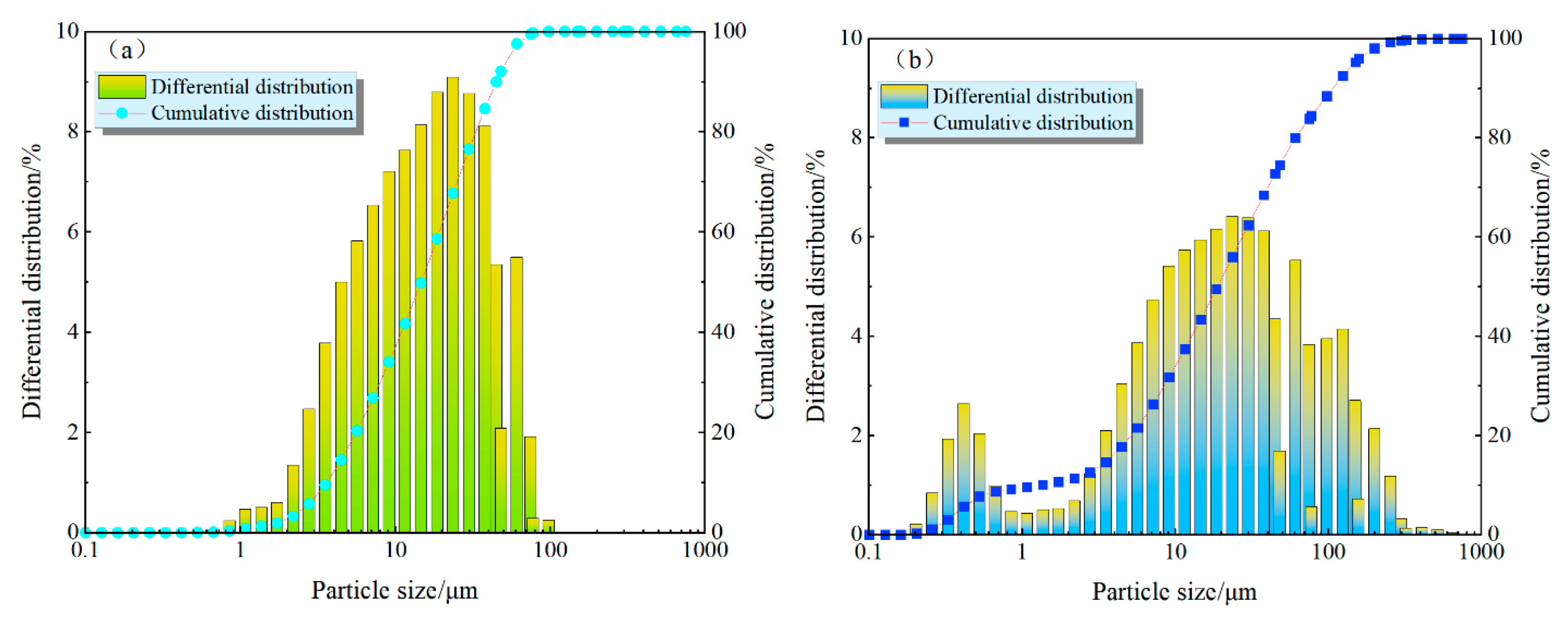
2.1.1. Cement, Gold Tails and Water

In the present research, Portland cement 42.5 R was used as the key cementing product. Recent gold-mine tails were used as the main components of CCTB. Before these two components are mixed, the tailings are placed in a constant temperature oven and dried at 100 degrees Celsius for 24 h. Then, dried gold mine tails are kept in wrapped storage to prevent further exposure to moist air. The percentage of particles of a certain size for gold mine tails and cement, which is crucial for CTB applications to better ensure functionality and safety was fixed by LSPOP (9) laser particle size analyses using laser diffraction (Omec, Zhuhai, China), and the results are shown in Figure 1. Nondistilled (tap) waters were mixed with gold-mine tails and cement to produce CTB specimens. It is worth noting that the effect of water mixing on the tested strength properties was neglected in this experiment.
Key oxidizing compositions of tail/cement products were explored via a sequential X-ray fluorescence spectrometer (XRF-1800, Shimadzu, Kyoto, Japan). The test parameters included a scanning speed of 300°/min, a voltage of 60 kV, and a current of 140 mA. Table 1 indicates tailings/cement products’ main oxide compositions.

2.1.2. Fiber

Low-elastic-modulus fibers can be employed in various functions in CTB, depending on their type, content, and length, and each parameter seriously affects its strength and stability behavior [64]. In this study, fiber-reinforced CCTBs were made up of PP fibers alone. Utilized as a fiber-reinforcing material, PP has a greater flexibility modulus and tensile strength than other types of fibers. PP fiber’s key parameters covered a fiber length of 12 mm, 0.89 g/cm3 density, 398 MPa tensile strength, and an elongation value of 28%.

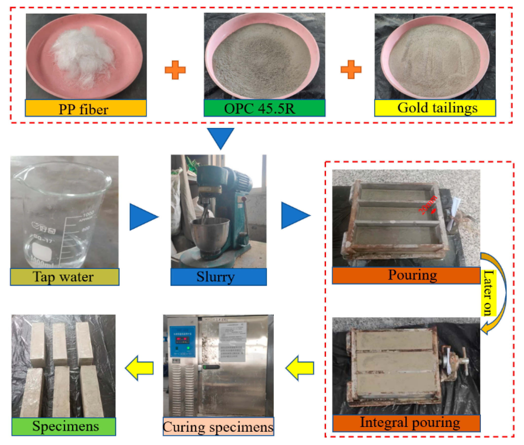
2.2. Preparation of Combined CTB Specimens

PP fiber’s impact on CCTB strength features was examined in the present study. The constant solid concentration and curing age of the backfill specimens were 70 wt% and 7 days, respectively. A cement/tail (c/t: 1:8 to 1:4) fraction was considered while using a fixed fiber dosage of 0.6 wt% [65]. A specimen size of 160 × 40 × 40 mm3 was used in the present study, and CCTB specimens were cast in two sequences, each sequence with a thickness of 20 mm, divided into 5 groups, and three fill samples were prepared individually, giving 15 samples in total. Table 2 shows the specific specimen preparation scheme, where NH indicates that the specimen’s lower layer does not contain fiber and H indicates that the specimen’s lower layer contains fiber.
Prior to conducting the experiments, lubrication of the mold walls was necessary to ensure that the specimens could be successfully demolded, and then a pencil was used to mark the end position of the first pour. A sensitive weighing scale (accuracy: 0.1 g) was used to precisely measure the weights of the cement, tailings, fiber, and water for the experiment. Note that fiber form clusters should be disconnected from each other prior to CTB mixing. After that, OPC 42.5R, gold tailings, and separated fiber were poured into a JJ-5 cement slurry mixer(the mixing speed was 140 r/min) for no less than 180 s, and nondistilling water was poured into continuous mixing for 180 s. Last, the manufactured backfills were cast in the model’s premarked position. After curing for 2 h, cement, gold tails, and nondistilling water were blended similarly and poured into the model to complete the secondary pouring. Finally, the specimens were cured in an HSBY-40B curing vessel at a fixed temperature (21 °C) and moisture (94%). After 2 days, the specimens were removed from molds and put back into the HSBY-40B curing vessel up to a cure age of 7 days. Figure 2 displays the making phases of CCTB specimens.

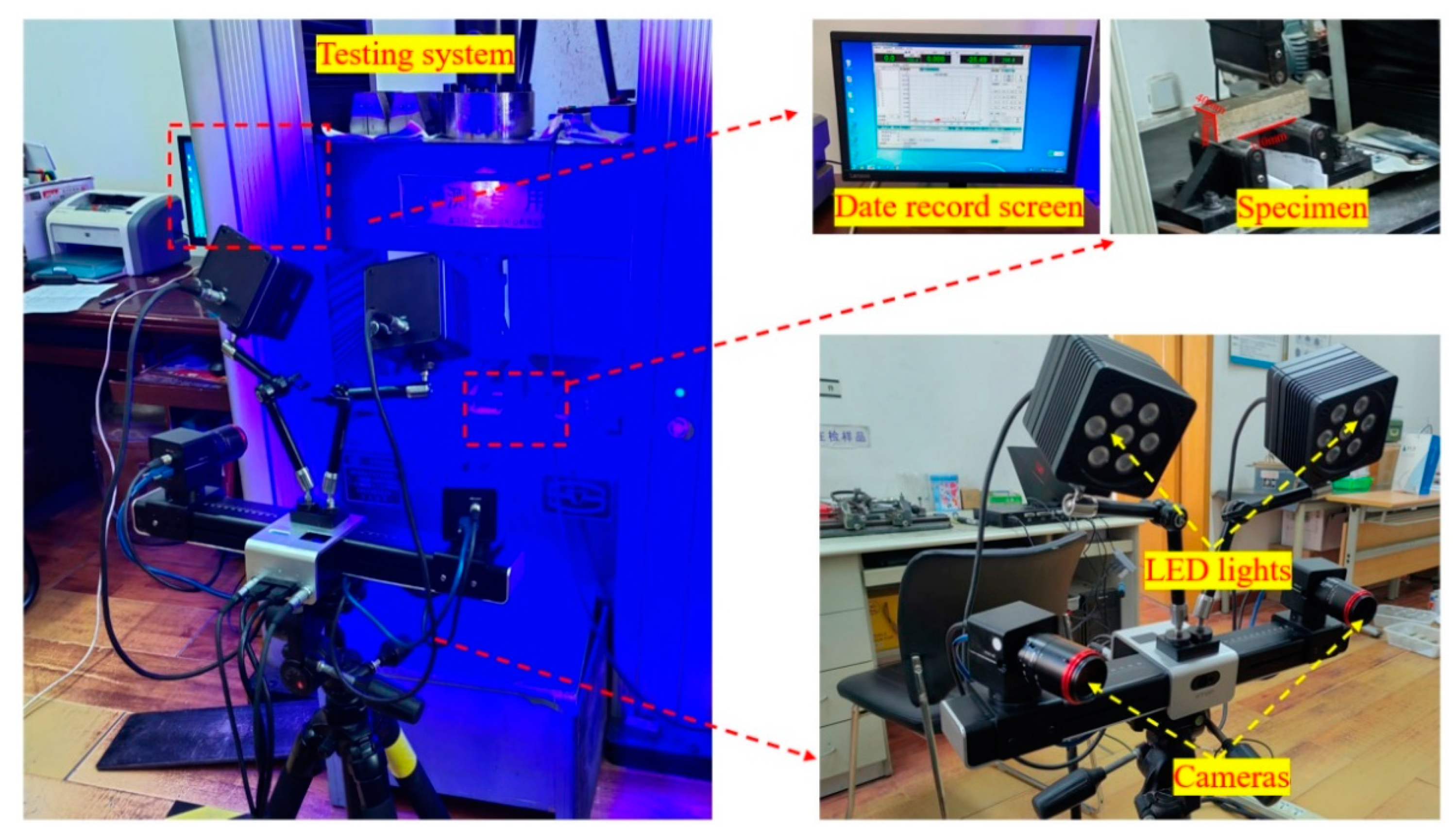
2.3. Three-Point Bending Test

A computer-controlled automatic and high-precision load cell test apparatus (with a 200 kN loading capacity) was employed for measuring CCTB flexural/deflection characteristics. A support point span of 110 mm was considered while a dislocation level of 0.5 mm per minute was considered. Data such as the CCTB’s load deflection and peak loads were automatically saved by a PC in the course of loading.

2.4. DIC Technique

To automatically save the loaded specimen’s damage process, a fast-moving 3D digital image correlation (3D-DIC) process with 3D optical/microscopic strain was employed. 3D-DIC follows the specimen surface’s scattered images to obtain measurements of the 3D coordinates, movement area, and fill surface’s strain area throughout the distortion. In the course of testing, one image per second is engaged and the specimen surface’s strain is measured to vary between 0.01% and 1000%. The specimen’s distortion route and data were acquired by capturing dots on the surface of the backfill with 3D-DIC, and all experimental data were then classified/processed. Figure 3 shows the principal details of the 3D-DIC system used.

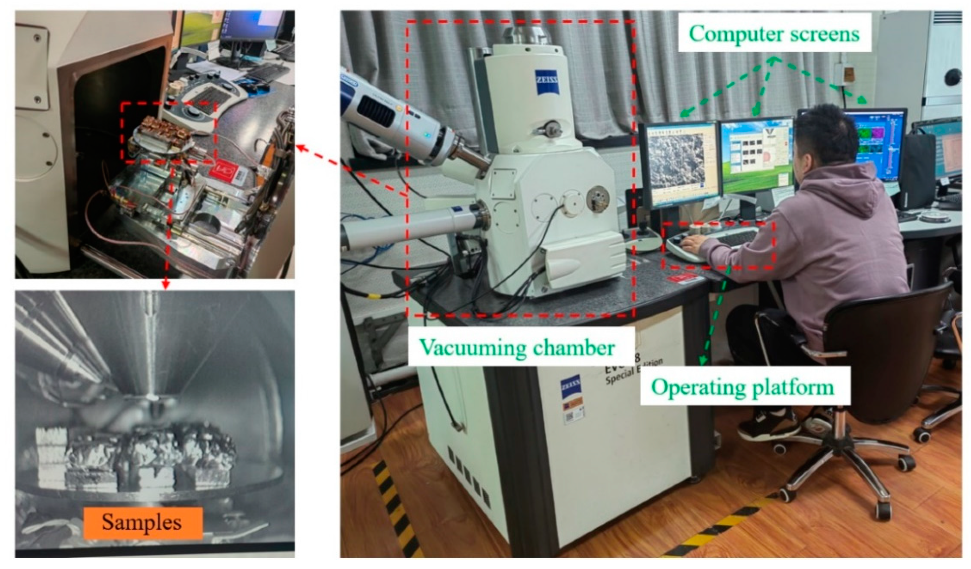
2.5. Microstructural Property Analysis

In this study, the microstructure of the assembled filling specimens was inspected by employing a Zeiss Evo 18 SEM device (Carl Zeiss AG, Oberkochen, Germany) (Figure 4). Following strength testing, specimens with sizes of 10 × 10 mm2 were received by ruptured backfill pieces, and the hydration process of cement was ended with ethanol. CCTB specimens were dried first and then carbon was sprayed on their surfaces twice by a vacuum coater to improve electrical conductivity prior to SEM observations. The prepared fill specimens were then positioned in a vacuum space for evacuation. The basic parameters of SEM covered an acceleration voltage of up to 20 kV, an extreme enlargement of 5000×, and a resolution of 3 nm. Note that microarea elements were also analyzed by EDS.

3. Results and Discussion

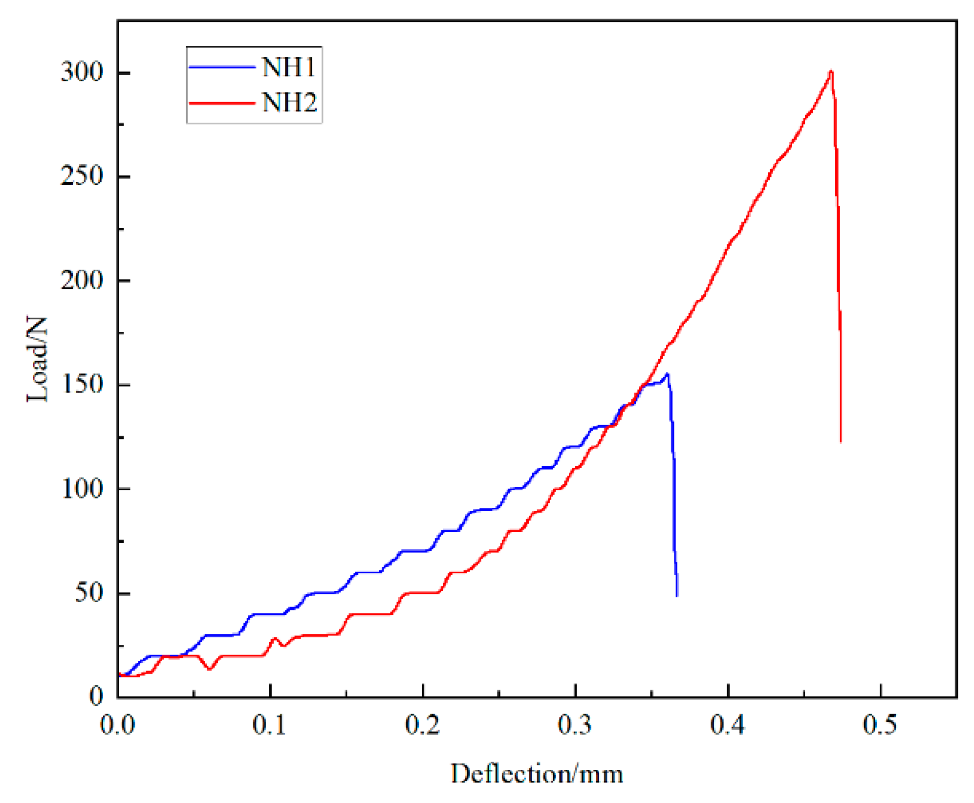
3.1. CCTB Bending Features

Along with the necessities of the three-point flexural experiments, an equation considered for determining CCTB flexural strength is expressed below (1):
σ = 3 P L 2 b h 2 ,
where P is the corresponding peak load, N; L is the space between two plugs, m; b is the cross section width, m; and h is the cross section height, m.
To inspect the impact of PP fiber on the flexural properties of the combined specimens, the following equation was used in this study to calculate the CCTB flexural strength increment ratio (2):
f f l e x = f H f N H f N H ,
where f f l e x is the portion of incremental flexural strength; f H is the flexural strength of CCTB with fiber, MPa; and f N H is the flexural strength of CCTB without fiber, MPa.
Figure 5 shows the average flexural strength (FS) of CCTB with fiber and the ratio of flexural strength increments under different c/t conditions. According to Figure 5a, the flexural strengths of groups H1, H2, and H3 of fiber-reinforced CCTB are 0.48, 0.56, and 0.63 MPa, respectively, which are greater than the flexural strength of 0.42 MPa for NH1 without fiber and less than the flexural strength of 0.81 MPa for NH2 without fiber.
Meanwhile, the flexural strength of fiber-containing CCTB gradually increased with increasing c/t fraction, and when the c/t portion was 1:4, its flexural strength was 1.17 and 1.30 times higher than those of CCTB with c/t fractions of 1:6 and 1:8, respectively. It is obvious from Figure 5b that the ratios of the incremental flexural strength of H1, H2, and H3 with fiber compared to NH1 and NH2 without fiber are 0.14, 0.33, 0.49, and −0.40, −0.30, and −0.22, respectively. The reason for this phenomenon is that when the c/t is low, the fiber can prevent crack growth in CCTB, improve the crack resistance of the combined CCTB, and thus improve the strength. However, with the increase of c/t, the addition of fibers also changes the original bond strength of CCTB, resulting in a decrease in strength. In addition, one can see that incorporating fiber into CCTB improves its flexural features when the cement content is low, but as the binder dosage is higher, adding fiber may also result in a decrease in its flexural properties.

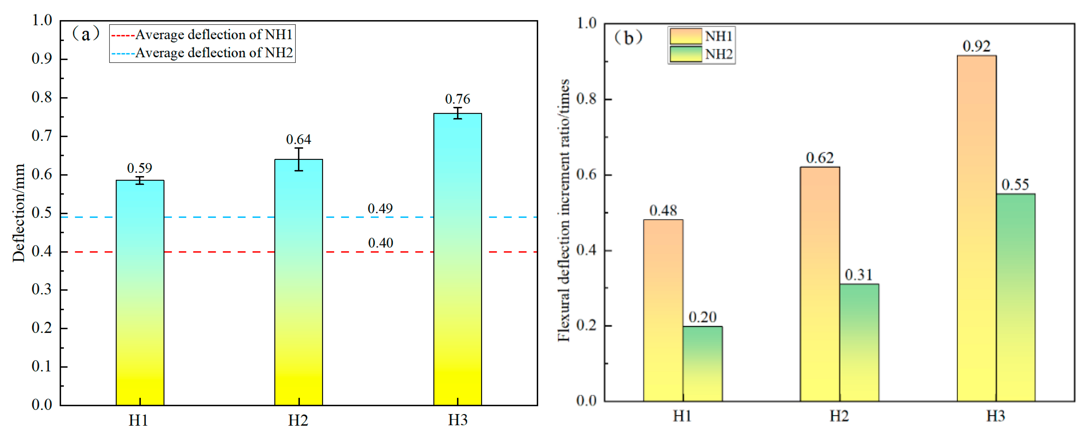
3.2. Deflection Characteristics of Composite Specimens

The addition of fiber in this flexural test changed the bending performance of CCTB. Peak deflection was used as the reference in this study and analyzed for each group of samples to investigate the reinforcing effect of fiber. The peak deflection is the linear displacement in the axial direction of the specimen between the initial load and the time that peak strength is extended, and the deflection increment fraction is totaled by Equation (3).
d f l e x = d H d N H d N H ,
where d f l e x is the fraction of the incremental bending deflection; d H is the peak deflection of CCTB with fiber, mm; and d N H is the peak deflection of CCTB without fiber, mm.
Figure 6 shows the peak deflection of CCTB with fiber and the ratio of the increment of peak deflection under different c/t conditions. According to Figure 6a, the peak deflection of the fiber-reinforced composite fillers H1, H2, and H3 are 0.59, 0.64, and 0.76 mm, respectively. With increasing c/t fraction, the peak deflection of CCTB with the fiber also increases in a stepwise manner, and the peak deflection is maximal as the c/t fraction is 1:4. Meanwhile, the peak deflection of all CCTBs with fiber was expressively more than that of NH1 and NH2 with no fiber. According to Figure 6b, it can be concluded that H1, H2, and H3 all obtain varying degrees of increase in the peak deflection increment compared with NH1 and NH2. The ratio of the peak deflection increment compared with NH1 is 0.48, 0.62, and 0.92, and the ratio of the peak deflection increment compared with NH2 is 0.20, 0.31, and 0.55.
The peak deflection increment rises with a growing c/t fraction in a linear increasing link with a growing c/t ratio. The possible reason for the increased deflection of CCTB with fiber is that fiber can also bridge cracks in CCTB. Fibers are able to fill tiny cracks and form Bridges, thereby improving the ductility and toughness of CCTB. The lower peak deflection of CCTB without fibers may be due to the hydration products that increase the flexural strength of CCTB but also exhibit small ductility and great fragility, such as concrete. One could deduce that adding fiber augmented CCTB’s peak deflection.

3.3. Failure Modes of Composite Specimens

Figure 7 illustrates the load–deflection trends of CCTB without fibers. It is apparent that the backfill specimens suddenly fracture when attaining the peak load, and the force drops directly from the peak load to zero and completely loses the load-carrying capacity.
To further improve the present research, the ideal optimal specimen H3 was selected for fracture evolution analysis by combining the data for investigation. Figure 8 expresses the fracture progress under the load–deflection curve of CCTB containing fiber with a c/t fraction of 1:4 and further examines fiber impact on CCTB flexural features.
Combining the damage process and load–deflection curves of the specimens points A, B, C, and D (mark the location with the star symbols) were designated for test verification, and the load–deflection trends of CCTBs with fiber were consistent with Figure 7 when the peak load was not reached (between A and B). However, after reaching the peak load, CCTBs with fiber did not damage immediately and showed obvious ductility characteristics. Cracks began to appear, which indicated that the matrix of the backfill specimens was damaged at this time, but there was a significant inhibitory effect of fiber on crack expansion. The crack gradually increases in size as loading progresses, but the CCTB sample devises a load-carrying capacity. A magnified view of the fracture surface shows that the fiber bridge prevents the collapse of the specimen. The above results showed that the sample with fiber had a certain load-bearing capability following damage, which indicated that adding fiber could develop CCTB flexural features.

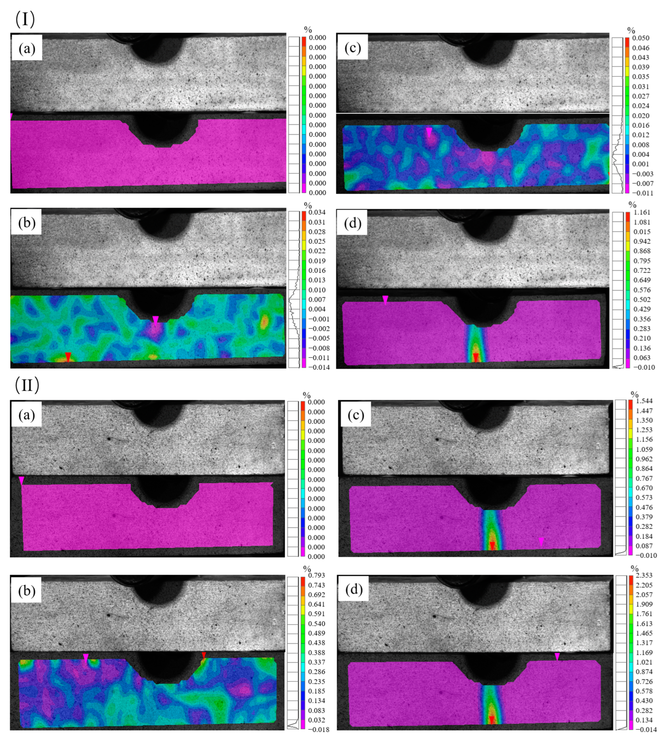
3.4. DIC Analysis of Load Deflection and Fracture Evolution

The surface displacements and strains of CCTBs during loading were obtained using the DIC technique. Since the tensile strain directly governs flexural damage, the strain was selected for analysis. The results showed that the specimens underwent the microcrack budding stage and macroscopic crack evolution stage before the specimens reached peak strength. Figure 9 shows the horizontal strain clouds of CCTB without fiber NH2 and CCTB specimens with fiber H3 as the load increased. It should be noted that the shaded part of Figure 9 shows the occlusion of specimens due to light from DIC equipment. At the early stage of loading, the tensile/compressive strains were small and the color distribution was uniform throughout the specimen without turning red. At this time, there were no major differences between the horizontal strains of NH2 and H3 specimens. As the loading increased, the color of both groups of samples deepened, while specimens as a whole turned blue, and the strain change was smaller for NH2 transformation than for H3 transformation, as well as when the damage occurred. The results show that the strain delivery and changes of H3 are more noticeable than those of NH2. The specimens’ stress distribution was relatively uniform at the beginning of loading, and no stress concentration was found; with the increased loading interval, the stresses of the two groups of samples progressively increased, the location of the main stresses changed, and the stresses were mostly focused on the middle of the specimen’s lower layer, which was more obviously reflected in the H3 specimen. In conclusion, the stresses occurring in the H3 specimens changed significantly due to the addition of fiber. By comparing the strain change amplitudes of the H3 and NH2 specimens, it was found that the strain change in the H3 specimens is more prominent than that in the NH2 specimens, which shows that the flexural features of the H3 specimens are more obvious than those of the NH2 specimens.

3.5. Energy Analysis of Composite Specimens

In this section, the energy consumption during the failure of CCTB was studied. The fracture energy is the energy required per unit area for crack expansion, which can be well obtained using the area under flexural strength deflection, and the ratio of the effect of fiber on the energy consumption of CCTB can be calculated by Equation (4):
γ f = G H G N H G N H
where γ f is the ratio of the fracture energy increment when CCTB with fiber and CCTB without fiber reach the peak strength, which means the value of fiber contribution to energy consumption; GH is the fracture energy when CCTB specimen with fiber reaches its peak strength, N/mm; and G N H is the fracture energy when CCTB specimen without fiber reaches its peak strength, N/mm.
Figure 10 shows the fracture energy of CCTB with fiber and the ratio of the incremental energy consumption when attaining peak strength. One can deduce that the fracture energy of CCTB with fiber at peak strength increases gradually with increasing c/t fraction, and the energy consumption for CCTB was highest for a c/t fraction of 1:4.
The peak strength energy consumption was 27.01, 57.21, and 63.28 N/mm, respectively. The energy consumption of H1, H2, and H3 was increased to different degrees compared to NH1 and NH2, with ratios of energy increments of 0.17, 1.47, and 1.69 in comparison with NH1 and ratios of energy increments of −0.44, 0.19, and 0.29 compared to NH2. In addition, the energy dissipated by the samples inclined to rise nonlinearly with a rise in deflection. Until reaching peak strength, the energy consumption required for CCTB with fiber shows a growing trend compared to CCTB without fiber. Thus, CCTB with fiber is more capable of dissipating energy, which helps prevent brittle damage.

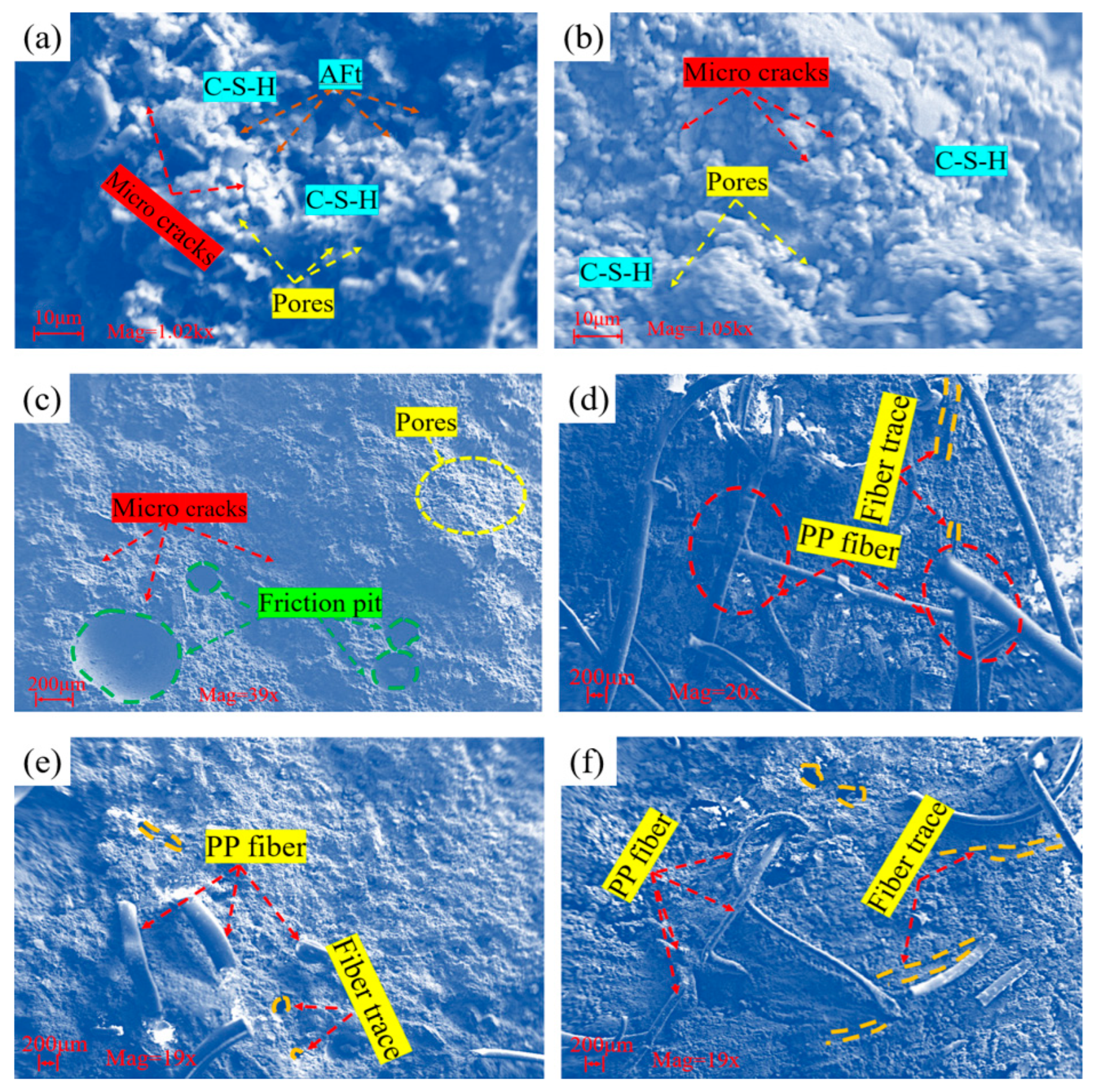
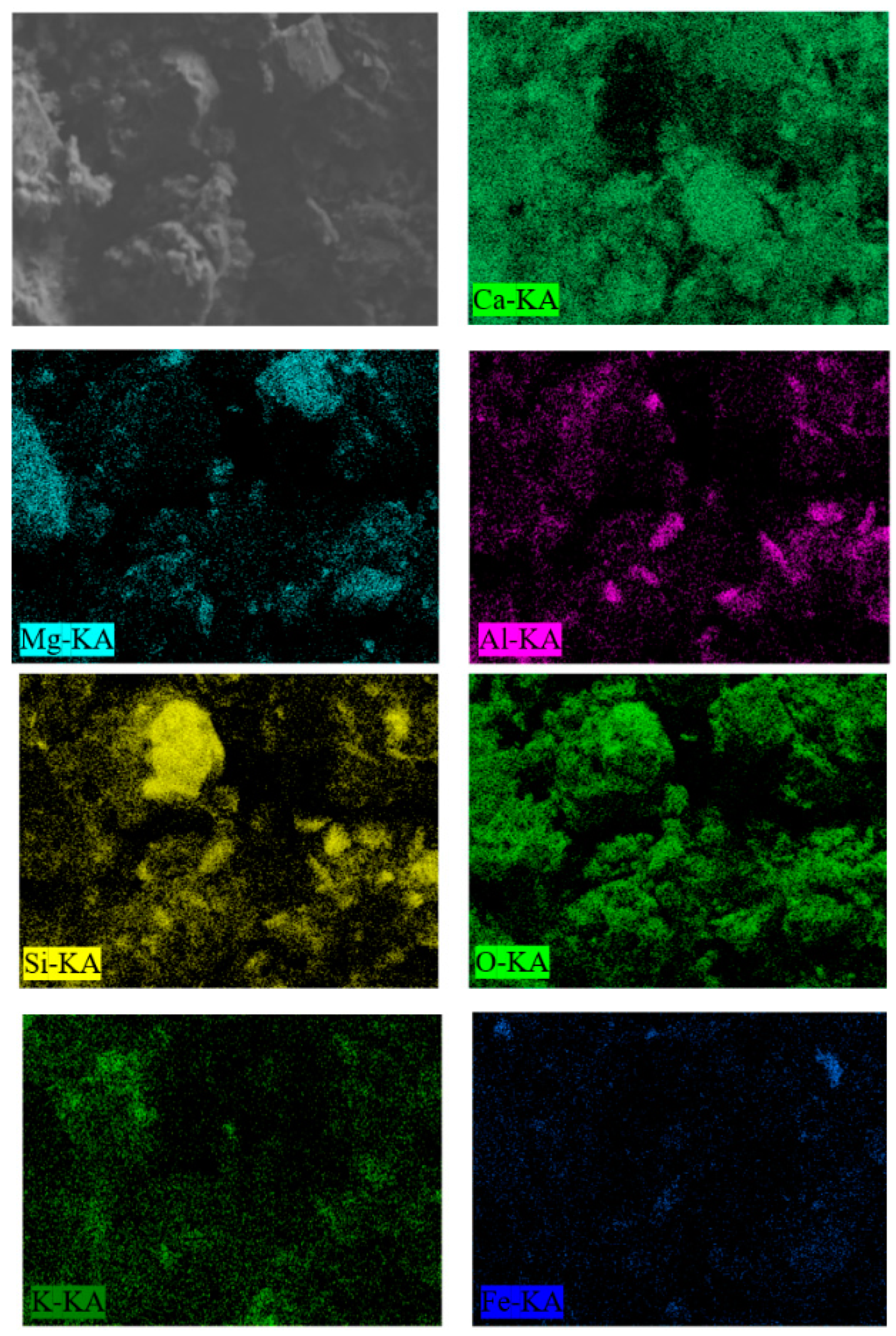
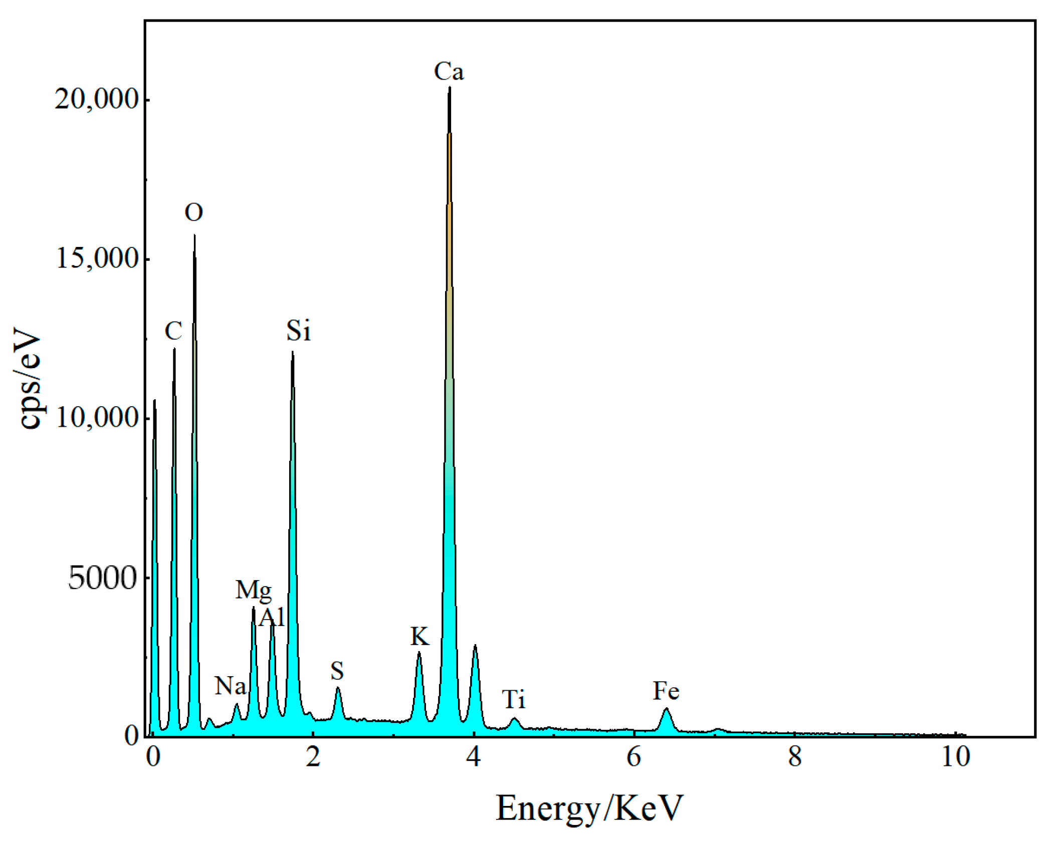
3.6. Microstructure of CCTB Samples

Figure 11 demonstrates SEM micrographs of the interior/surface between the layers of each type of CCTB specimen. One could state that CCTB’s hydration materials were mainly ettringite and CSH gels by magnifying the micrographs one thousand times.
Figure 11a–c show that in addition to hydration products, pores, and microcracks were generated in specimens, and the contact surfaces of the combination’s upper/lower layers also rubbed when they were subjected to forces so that friction pits could be clearly observed on the contact surfaces. Figure 11d–f show that in the contact surface, the fibers and the internal structure of CCTBs form a well-through connection, which connects the fibers and the combination into a whole and improves the flexural performance of CCTBs. One can observe that hydration materials were enfolded on the fiber surface, and most of the fibers were broken or deformed. Some fibers were entangled, which was mainly due to the deformation of the fiber when the mixer was stirring. In the pulled fiber and the scratches produced by the fiber, it can be found that the diameter of the fiber decreases and is different in size. This may be related to the fact that the PP fiber was pulled off under load and the fiber was subjected to uneven forces, which also specified that PP fiber was susceptible to distortion.
As an example, for specimen H3, Figure 12 and Figure 13 show the distribution and the total distribution spectrum of the main elements mapped for CCTBs, respectively. From these two diagrams, it can be concluded that the main elements in CCTB specimens are O, Ca, Si, Mg, and Fe, of which oxygen has the maximum content and its constituents are a variety of hydration materials. The CCTB specimens mainly consisted of four materials: anhydrous clinker, fiber, and inert/hydration products. Meanwhile, a comparison of micrographs with the distribution positions of the main elements showed that the three main elements of Si, O, and Ca were more concentrated near CSH gels. To some extent, the presence of CSH gels can improve CCTB flexural strength features.

4. Conclusions

To inspect the impact of PP fiber on CCTB flexural properties, three-point bending tests were directed, and the load–deflection relationship was examined by employing a DIC system. In addition, SEM-EDS interpretations were carried out on CCTB specimens to portray the reinforcing impact of PP fibers on CCTB specimens. The following conclusions were drawn:
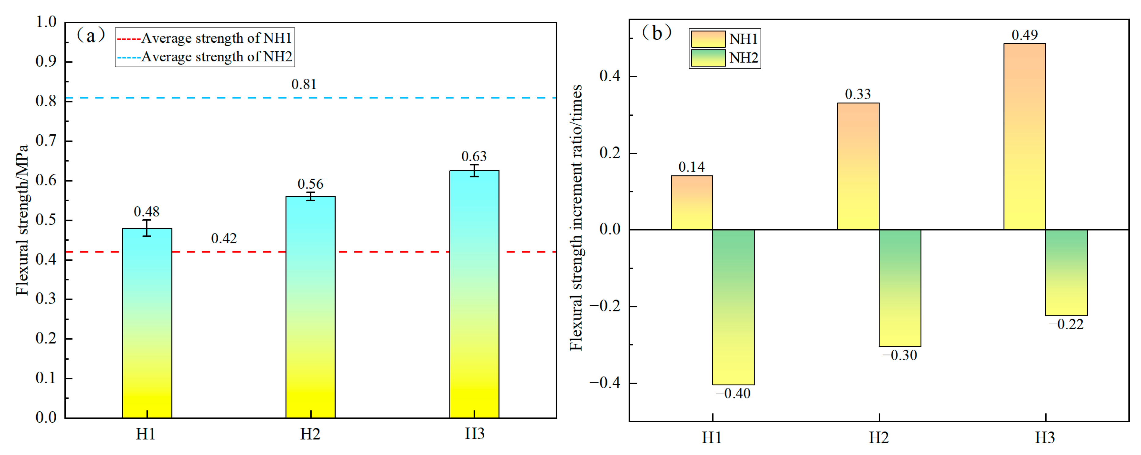
  • The flexural strength of NH2 of CCTB specimens without fiber was maximum and the flexural strength of CCTB specimens without fiber was minimum for a 7-day curing age. The flexural strength of CCTB specimens with fibers increased with increasing c/t fraction;
  • Adding fiber improved CCTB flexural properties when the c/t fraction was low, but adding fiber may also lead to a drop in the flexural features of backfilling as the c/t fraction was high;
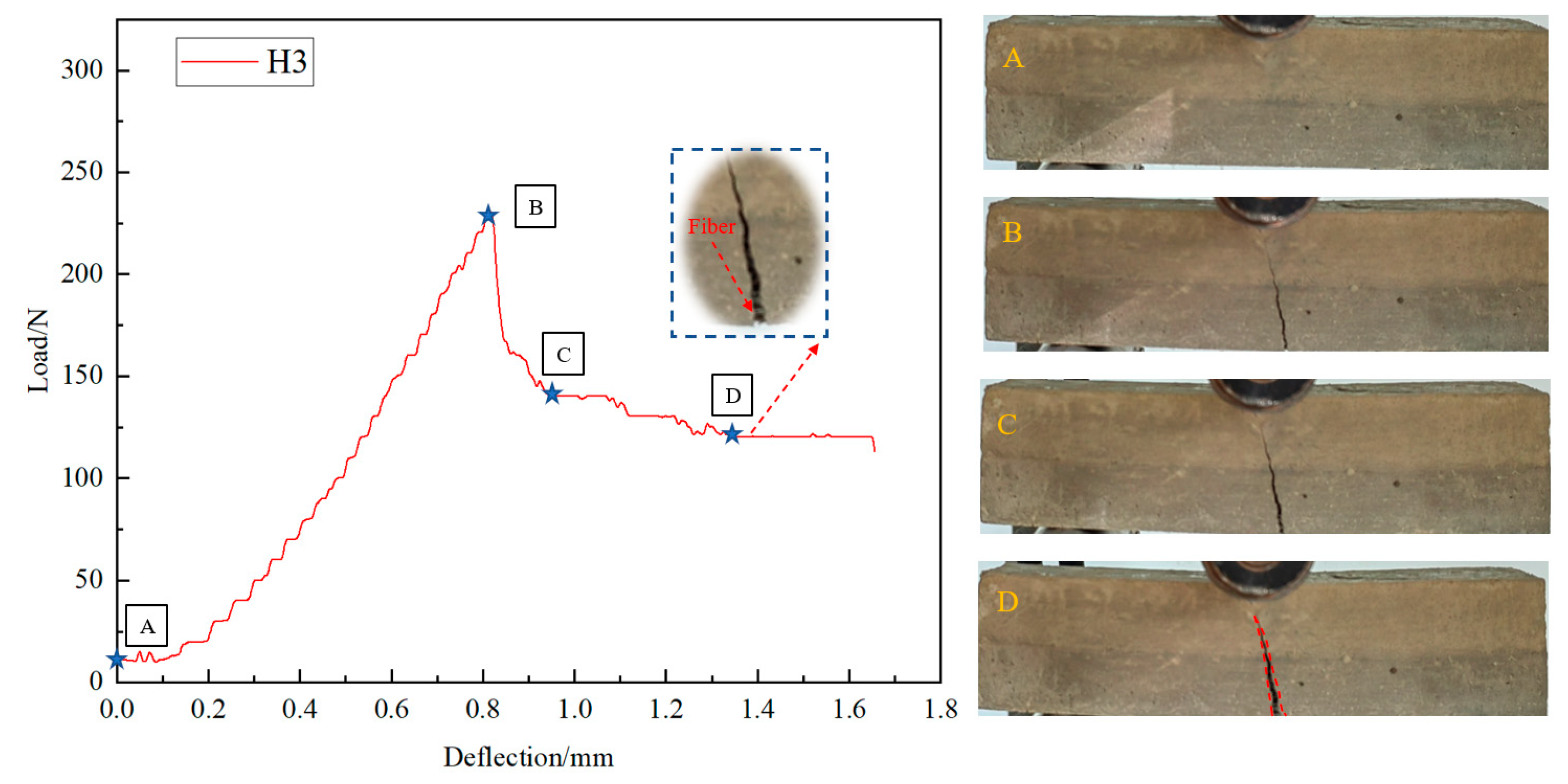
  • With PP fiber addition, CCTB’s peak deflection was improved significantly, and the increment of peak deflection showed a linear rise with increasing c/t fraction. The key reason for the low peak deflection of CCTB without fibers may be that it exhibited low ductility and high brittleness. Thus, adding fiber can shift CCTB’s rupture behavior from brittle to ductile;
  • The failure of the composite backfill starts from the bottom center, and the key reason for rupture is the stress concentration at the bottom. When failure was reached, the strain rate generated by CCTB with fibers was larger than that of CCTB without fibers. Adding PP fibers effectively deterred crack expansion, and the fiber bridging impact on cracks effectively enriched CCTB flexural features;
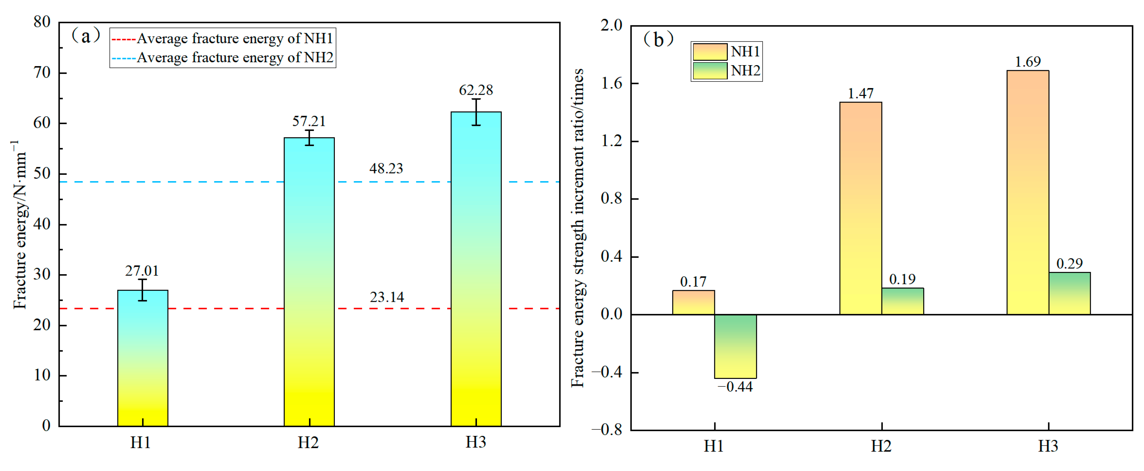
  • The energy dissipated by CCTB samples exhibited a nonlinear progress tendency with growing deflection. With the addition of PP fiber, the energy consumption of specimens increased, and the energy consumption capacity became stronger, which can help prevent brittle damage.

Author Contributions

Conceptualization, S.C.; methodology, X.L.; writing—original draft preparation, X.L.; writing—review and editing and supervision, E.Y. and S.C.; funding acquisition, S.C. All authors have read and agreed to the published version of the manuscript.

Funding

We want to honorably recognize substantial funds being granted by the National Key Research and Development Program of China (with a grant number of 2022YFC2905004).

Data Availability Statement

Data are contained within the article.

Conflicts of Interest

The authors declare no conflicts of interest.

References

  1. Atienza, M.; Lufin, M.; Soto, J. Mining linkages in the Chilean copper supply network and regional economic development. Resour. Policy 2021, 70, 101154. [Google Scholar] [CrossRef]
  2. Sari, M.; Yilmaz, E.; Kasap, T. Long-term ageing characteristics of cemented paste backfill: Usability of sand as a partial substitute of hazardous tailings. J. Clean. Prod. 2023, 401, 136723. [Google Scholar] [CrossRef]
  3. Szamałek, K.; Zglinicki, K.; Mazurek, S.; Szuflicki, M.; Rameignies, I.S.; Tymiński, M. The role of mineral resources knowledge in the economic planning and development in Poland. Resour. Policy 2021, 74, 102354. [Google Scholar] [CrossRef]
  4. Mardonova, M.; Han, Y.-S. Environmental, hydrological, and social impacts of coal and nonmetal minerals mining operations. J. Environ. Manag. 2023, 332, 117387. [Google Scholar] [CrossRef]
  5. Li, H.; Yao, J.; Min, N.; Duran, R. Comprehensive assessment of environmental and health risks of metal(loid)s pollution from non-ferrous metal mining and smelting activities. J. Clean. Prod. 2022, 375, 134049. [Google Scholar] [CrossRef]
  6. Wu, X.; Wang, S.; Gao, E.; Chang, L.; Ji, C.; Ma, S.; Li, T. Failure mechanism and stability control of surrounding rock in mining roadway with gentle slope and close distance. Eng. Fail. Anal. 2023, 152, 107489. [Google Scholar] [CrossRef]
  7. Zhang, Z.-X. Lost-ore mining—A supplementary mining method to sublevel caving. Int. J. Rock Mech. Min. Sci. 2023, 168, 105420. [Google Scholar] [CrossRef]
  8. Sun, Q.; Wei, X.; Wen, Z. Preparation and strength formation mechanism of surface paste disposal materials in coal mine collapse pits. J. Mater. Res. Technol. 2022, 17, 1221–1231. [Google Scholar] [CrossRef]
  9. Salmi, E.; Nazem, M.; Karakus, M. Numerical analysis of a large landslide induced by coal mining subsidence. Eng. Geol. 2017, 217, 141–152. [Google Scholar] [CrossRef]
  10. Wolkersdorfer, C.; Walter, S.; Mugova, E. Perceptions on mine water and mine flooding—An example from abandoned West German hard coal mining regions. Resour. Policy 2022, 79, 103035. [Google Scholar] [CrossRef]
  11. Chang, M.; Dou, X.; Tang, L.; Xu, H. Risk assessment of multi-disaster in Mining Area of Guizhou, China. Int. J. Disaster Risk Reduct. 2022, 78, 103128. [Google Scholar] [CrossRef]
  12. Wang, Y.; Wang, Z.; Wu, A.; Wang, L.; Na, Q.; Cao, C.; Yang, G. Experimental research and numerical simulation of the multi-field performance of cemented paste backfill: Review and future perspectives. Int. J. Miner. Metall. Mater. 2023, 30, 193–208. [Google Scholar] [CrossRef]
  13. He, X.; Yuhua, Z.; Qaidi, S.; Isleem, H.F.; Zaid, O.; Althoey, F.; Ahmad, J. Mine tailings-based geopolymers: A comprehensive review. Ceram. Int. 2022, 48, 24192–24212. [Google Scholar] [CrossRef]
  14. Niu, H.; Wang, J.; Jing, Z.; Liu, B. Identification and management of land use conflicts in mining cities: A case study of Shuozhou in China. Resour. Policy 2023, 81, 103301. [Google Scholar] [CrossRef]
  15. Zhang, X.; Nie, W.; Peng, H.; Chen, D.; Du, T.; Yang, B.; Niu, W. Onboard air curtain dust removal method for longwall mining: Environmental pollution prevention. J. Environ. Chem. Eng. 2021, 9, 106387. [Google Scholar] [CrossRef]
  16. Ali, M.; Pal, I. Assessment of workers’ safety behavior in the extractive industries: The case of underground coal mining in Pakistan. Extr. Ind. Soc. 2022, 10, 101087. [Google Scholar] [CrossRef]
  17. Kaung, P.F.; Semikin, A.A.; Khayrutdinov, A.M.; Dekhtyarenko, A.A. Recycling of industrial waste is a paradigm of resource provision for sustainable development. Sustain. Dev. Mt. Territ. 2023, 15, 385–397. [Google Scholar] [CrossRef]
  18. Yang, L.; Li, J.; Liu, H.; Jiao, H.; Yin, S.; Chen, X.; Yu, Y. Systematic review of mixing technology for recycling waste tailings as cemented paste backfill in mines in China. Int. J. Miner. Metall. Mater. 2023, 30, 1430–1443. [Google Scholar] [CrossRef]
  19. Kovalski, E.R.; Kongar-Syuryun, C.B.; Petrov, D.N. Challenges and prospects for several-stage stoping in potash minining. Sustain. Dev. Mt. Territ. 2023, 15, 349–364. [Google Scholar] [CrossRef]
  20. Kongar-Syuryun, C.B.; Aleksakhin, A.V.; Eliseeva, E.N.; Zhaglovskaya, A.V.; Klyuev, R.V.; Petrusevich, D.A. Modern technologies providing a full cycle of geo-resources development. Resources 2023, 12, 50. [Google Scholar] [CrossRef]
  21. Cheng, A.; Zhou, C.; Huang, S.; Zhang, Y.; Pei, M. Study on the nonlinear deformation characteristics and constitutive model of cemented tailings backfill considering compaction hardening and strain softening. J. Mater. Res. Technol. 2022, 19, 4627–4644. [Google Scholar] [CrossRef]
  22. Holmberg, B.; Cui, L. Multiphysics processes in the interfacial transition zone of fiber-reinforced cementitious composites under induced curing pressure and implications for mine backfill materials: A critical review. Int. J. Miner. Metall. Mater. 2023, 30, 1474–1489. [Google Scholar] [CrossRef]
  23. Fang, K.; Yang, J.; Wang, Y. Comparison of the mode I fracture toughness of different cemented paste backfill-related structures: Effects of mixing recipe. Eng. Fract. Mech. 2022, 270, 108579. [Google Scholar] [CrossRef]
  24. Guo, Z.; Qiu, J.; Kirichek, A.; Zhou, H.; Liu, C.; Yang, L. Recycling waste tyre polymer for production of fibre reinforced cemented tailings backfill in green mining. Sci. Total Environ. 2024, 908, 168320. [Google Scholar] [CrossRef] [PubMed]
  25. Wang, Y.; Na, Q.; Zhang, L.F. Monitoring of in-situ properties for cemented tailings backfill that under drainage condition. Constr. Build. Mater. 2022, 356, 129254. [Google Scholar] [CrossRef]
  26. Hou, Y.; Yin, S.; Yang, S.; Chen, X.; Du, H. Mechanical properties, damage evolution and energy dissipation of cemented tailings backfill under impact loading. J. Build. Eng. 2023, 66, 105912. [Google Scholar] [CrossRef]
  27. Saedi, A.; Jamshidi-Zanjani, A.; Darban, A.K. A review of additives used in the cemented paste tailings: Environmental aspects and application. J. Environ. Manag. 2021, 289, 112501. [Google Scholar] [CrossRef]
  28. Zhang, X.; Xue, X.; Ding, D.; Gu, Y.; Sun, P. Feasibility of uranium tailings for cemented backfill and its environmental effects. Sci. Total Environ. 2023, 863, 160863. [Google Scholar] [CrossRef]
  29. Xu, W.B.; Cao, Y.; Liu, B.H. Strength efficiency evaluation of cemented tailings backfill with different stratified structures. Eng. Struct. 2019, 180, 18–28. [Google Scholar] [CrossRef]
  30. Cui, L.; McAdie, A. Experimental study on evolutive fracture behavior and properties of sulfate-rich fiber-reinforced cemented paste backfill under pure mode-I, mode-II, and mode-III loadings. Int. J. Rock Mech. Min. Sci. 2023, 169, 105434. [Google Scholar] [CrossRef]
  31. Yin, S.; Yan, Z.; Chen, X.; Yan, R.; Chen, D.; Chen, J.; Li, G. Active roof-contact: The future development of cemented paste backfill. Constr. Build. Mater. 2023, 370, 130657. [Google Scholar] [CrossRef]
  32. Vennes, I.; Mitri, H.; Chinnasane, D.R.; Yao, M. Large-scale destress blasting for seismicity control in hard rock mines: A case study. Int. J. Min. Sci. Technol. 2020, 30, 141–149. [Google Scholar] [CrossRef]
  33. Zhao, K.; Yang, J.; Yu, X.; Yan, Y.; Zhao, K.; Lai, Y.; Wu, J. Damage evolution process of fiber-reinforced backfill based on acoustic emission three-dimensional localization. Compos. Struct. 2023, 309, 116723. [Google Scholar] [CrossRef]
  34. Wang, J.; Yu, Q.; Xiang, Z.; Fu, J.; Wang, L.; Song, W. Influence of basalt fiber on pore structure, mechanical performance and damage evolution of cemented tailings backfill. J. Mater. Res. Technol. 2023, 27, 5227–5242. [Google Scholar] [CrossRef]
  35. Shen, Z.; Liu, W.; Zhang, Q. Tensile behavior of high-performance interlayer hybrid composites of polypropylene and glass fiber for civil engineering. Constr. Build. Mater. 2023, 403, 133017. [Google Scholar] [CrossRef]
  36. Chen, X.; Shi, X.; Zhou, J.; Chen, Q.; Li, E.; Du, X. Compressive behavior and microstructural properties of tailings polypropylene fibre-reinforced cemented paste backfill. Constr. Build. Mater. 2018, 190, 211–221. [Google Scholar] [CrossRef]
  37. Chakilam, S.; Cui, L. Effect of polypropylene fiber content and fiber length on the saturated hydraulic conductivity of hydrating cemented paste backfill. Constr. Build. Mater. 2020, 262, 120854. [Google Scholar] [CrossRef]
  38. Yang, J.; Zhao, K.; Yu, X.; Yan, Y.; He, Z.; Zhou, Y.; Lai, Y. Fracture evolution of fiber-reinforced backfill based on acoustic emission fractal dimension and b-value. Cem. Concr. Compos. 2022, 134, 104739. [Google Scholar] [CrossRef]
  39. Yin, S.; Hou, Y.; Chen, X.; Zhang, M.; Du, H.; Gao, C. Mechanical behavior, failure pattern and damage evolution of fiber-reinforced cemented sulfur tailings backfill under uniaxial loading. Constr. Build. Mater. 2022, 332, 127248. [Google Scholar] [CrossRef]
  40. Xue, X.; Gu, Y.; Zhang, X.; Wu, S.; Sun, P.; Cui, J.; Wang, X. Mechanical behavior and microscopic mechanism of fiber reinforced coarse aggregate cemented backfill. Constr. Build. Mater. 2023, 366, 130093. [Google Scholar] [CrossRef]
  41. Li, J.J.; Cao, S.; Yilmaz, E. Analyzing the microstructure of cemented fills adding polypropylene-glass fibers with X-ray micro-computed tomography. J. Mater. Res. Technol. 2023, 27, 2627–2640. [Google Scholar] [CrossRef]
  42. Yi, X.W.; Ma, G.W.; Fourie, A. Centrifuge model studies on the stability of fibre-reinforced cemented paste backfill stopes. Geotext. Geomembr. 2018, 46, 396–401. [Google Scholar] [CrossRef]
  43. Hao, J.; Zhou, Z.; Chen, Z.; Zhou, Y.; Wang, J. Damage characterization and microscopic mechanism of steel slag-cemented paste backfill under uniaxial compression. Constr. Build. Mater. 2023, 409, 134175. [Google Scholar] [CrossRef]
  44. Zhao, K.; Lai, Y.; He, Z.; Liu, W.; Zhao, R.; Wang, Y.; Tian, X.; Nie, J. Study on energy dissipation and acoustic emission characteristics of fiber tailings cemented backfill with different ash-sand ratios. Process Saf. Environ. Prot. 2023, 174, 983–996. [Google Scholar] [CrossRef]
  45. Qi, C.; Fourie, A. Cemented paste backfill for mineral tailings management: Review and future perspectives. Miner. Eng. 2019, 144, 106025. [Google Scholar] [CrossRef]
  46. Yu, Z.; Shi, X.Z.; Chen, X.; Zhou, J.; Qi, C.C.; Chen, Q.S.; Rao, D.J. Artificial intelligence model for studying unconfined compressive performance of fiber-reinforced cemented paste backfill. Trans. Nonferrous Met. Soc. China 2021, 31, 1087–1102. [Google Scholar] [CrossRef]
  47. Chen, X.; Jiao, H.; Liu, J.; Yang, Y.; Chen, X.; Yang, L.; Zhang, W.; Yang, T. The Influence of Multi-Size Basalt Fiber on Cemented Paste Backfill Mechanical Properties and Meso-Structure Characteristics. Minerals 2023, 13, 1215. [Google Scholar] [CrossRef]
  48. Wang, A.A.; Cao, S.; Yilmaz, E. Effect of height to diameter ratio on dynamic characteristics of cemented tailings backfills with fiber reinforcement through impact loading. Constr. Build. Mater. 2022, 322, 126448. [Google Scholar] [CrossRef]
  49. Li, J.J.; Cao, S.; Song, W.D. Distribution development of pore/crack expansion and particle structure of cemented solid-waste composites based on CT and 3D. Constr. Build. Mater. 2023, 376, 130966. [Google Scholar] [CrossRef]
  50. Huang, Z.Q.; Cao, S.; Qin, S.W. Research on the mechanical properties of 3D printing polymer reinforced cemented tailings backfill under uniaxial compression. Geotech. Geol. Eng. 2022, 40, 3255–3266. [Google Scholar] [CrossRef]
  51. Yang, J.; Zhao, K.; Yu, X.; Yan, Y.; He, Z.; Lai, Y.; Zhou, Y. Crack classification of fiber-reinforced backfill based on Gaussian mixed moving average filtering method. Cem. Concr. Compos. 2022, 134, 104740. [Google Scholar] [CrossRef]
  52. Zhou, N.; Du, E.; Zhang, J.; Zhu, C.; Zhou, H. Mechanical properties improvement of Sand-Based cemented backfill body by adding glass fibers of different lengths and ratios. Constr. Build. Mater. 2021, 280, 122408. [Google Scholar] [CrossRef]
  53. Sun, W.; Gao, T.; Zhao, J.; Cheng, H. Research on fracture behavior and reinforcement mechanism of fiber-reinforced locally layered backfill: Experiments and models. Constr. Build. Mater. 2023, 366, 130186. [Google Scholar] [CrossRef]
  54. Wang, Y.; Yu, Z.; Wang, H. Experimental investigation on some performance of rubber fiber modified cemented paste backfill. Constr. Build. Mater. 2021, 271, 121586. [Google Scholar] [CrossRef]
  55. Wang, S.; Song, X.; Chen, Q.; Wang, X.; Wei, M.; Ke, Y.; Luo, Z. Mechanical properties of cemented tailings backfill containing alkalized rice straw of various lengths. J. Environ. Manag. 2020, 276, 111124. [Google Scholar] [CrossRef]
  56. Liu, W.; Yu, H.; Wang, S.; Wei, M.; Wang, X.; Tao, T.; Song, X. Evolution mechanism of mechanical properties of cemented tailings backfill with partial replacement of cement by rice straw ash at different binder content. Powder Technol. 2023, 419, 118344. [Google Scholar] [CrossRef]
  57. Ermolovich, E.A.; Ivannikov, A.L.; Khayrutdinov, M.M.; Kongar-Syuryun, C.B.; Tyulyaeva, Y.S. Creation of a nanomodified backfill based on the waste from enrichment of water-soluble ores. Materials 2022, 15, 3689. [Google Scholar] [CrossRef] [PubMed]
  58. Libos, I.L.S.; Cui, L.; Liu, X. Effect of curing temperature on time-dependent shear behavior and properties of polypropylene fiber-reinforced cemented paste backfill. Constr. Build. Mater. 2021, 311, 125302. [Google Scholar] [CrossRef]
  59. Qin, S.W.; Cao, S.; Yilmaz, E.; Li, J.J. Influence of types and shapes of 3D printed polymeric lattice on ductility performance of cementitious backfill composites. Constr. Build. Mater. 2021, 307, 124973. [Google Scholar] [CrossRef]
  60. Hao, W.; Liu, J.; Kanwal, H. Compressive properties of cementitious composites reinforced by 3D printed PA 6 lattice. Polym. Test. 2023, 117, 107811. [Google Scholar] [CrossRef]
  61. Gao, T.; Sun, W.; Liu, Z.; Cheng, H. Investigation on fracture characteristics and failure pattern of inclined layered cemented tailings backfill. Constr. Build. Mater. 2022, 343, 128110. [Google Scholar] [CrossRef]
  62. Cao, S.; Song, W.D. Effect of filling interval time on the mechanical strength and ultrasonic properties of cemented coarse tailing backfill. Int. J. Miner. Process. 2017, 166, 62–68. [Google Scholar] [CrossRef]
  63. Ma, G.W.; Li, Z.J.; Yi, X.W.; Guo, L.J. Macro-meso experiment of fiber-reinforced cement paste filling material. J. Beijing Univ. Technol. 2016, 42, 406–412. [Google Scholar]
  64. Zhang, H.; Cao, S.; Yilmaz, E. Carbon nanotube reinforced cementitious tailings composites: Links to mechanical and microstructural characteristics. Constr. Build. Mater. 2023, 365, 130123. [Google Scholar] [CrossRef]
  65. Xue, G.L.; Yilmaz, E.; Song, W.D.; Yilmaz, E. Influence of fiber reinforcement on mechanical behavior and micro-structural properties of cemented tailings backfill. Constr. Build. Mater. 2019, 213, 275–285. [Google Scholar] [CrossRef]
Figure 1. The differential/cumulative percentages of the cement (a) and tail (b) particles.
Minerals 14 00212 g001
Figure 2. CCTB’s manufacturing phases covering the ingredients/tools.
Minerals 14 00212 g002
Figure 3. The principal diagram of 3D-DIC strain measurement technology.
Minerals 14 00212 g003
Figure 4. The Zeiss Evo 18 SEM system and some photos.
Minerals 14 00212 g004
Figure 5. CCTB containing diverse c/t ratios: (a) FS and (b) the ratio of FS increment.
Minerals 14 00212 g005
Figure 6. CCTB with diverse c/t fractions: (a) peak deflection and (b) ratio of peak deflection increment.
Minerals 14 00212 g006
Figure 7. Load deflection trends of CCTB specimens with no fiber.
Minerals 14 00212 g007
Figure 8. Failure styles of CCTBs covering some rupture photos taken during the test: (A) initial equilibrium state; (B) peak intensity state; (C) crack propagation state; (D) post rupture state.
Minerals 14 00212 g008
Figure 9. Comparison of displacement clouds with actual objects under DIC images: (I) specimen NH2 ((a) initial equilibrium state; (b) initial crack generation; (c,d) crack evolution deepens); (II) specimen H3 ((a) initial equilibrium state; (b) initial crack generation; (c,d) crack evolution deepens).
Minerals 14 00212 g009
Figure 10. Different CCTB specimens: (a) fracture energy and (b) fraction of incremental fracture energy.
Minerals 14 00212 g010
Figure 11. Microstructure of the CCTB contact surface: (a,b) NH1; (c) NH2; (d) H1; (e) H2; and (f) H3.
Minerals 14 00212 g011
Figure 12. Mapping distribution of the main components of specimen H3.
Minerals 14 00212 g012
Figure 13. Total elemental distribution spectrum of specimen H3.
Minerals 14 00212 g013
Table 1. Gold mine tail and cement chemical composition.
Chemical CompositionSO2Al2O3CaOFe2O3MgOK2OSO3
Tailings (%)19.16.356.47.17.91.30.7
OPC 42.5R (%)24.6952.24.13.50.94.1
Table 2. Preparation scheme for each group of specimens.
GroupUpper LayerLower Layer
C/T RatioThickness (mm)Fiber (wt%)C/T RatioThickness (mm)Fiber (wt%)
NH11:82001:8200
NH21:82001:4200
H11:82001:8200.6
H21:82001:6200.6
H31:82001:4200.6
Disclaimer/Publisher’s Note: The statements, opinions and data contained in all publications are solely those of the individual author(s) and contributor(s) and not of MDPI and/or the editor(s). MDPI and/or the editor(s) disclaim responsibility for any injury to people or property resulting from any ideas, methods, instructions or products referred to in the content.

