


Increase in Recovery Efficiency of Iron-Containing Components from Ash and Slag Material (Coal Combustion Waste) by Magnetic Separation


 ,
,  ,
,
Abstract
1. Introduction
2. Materials and Methods
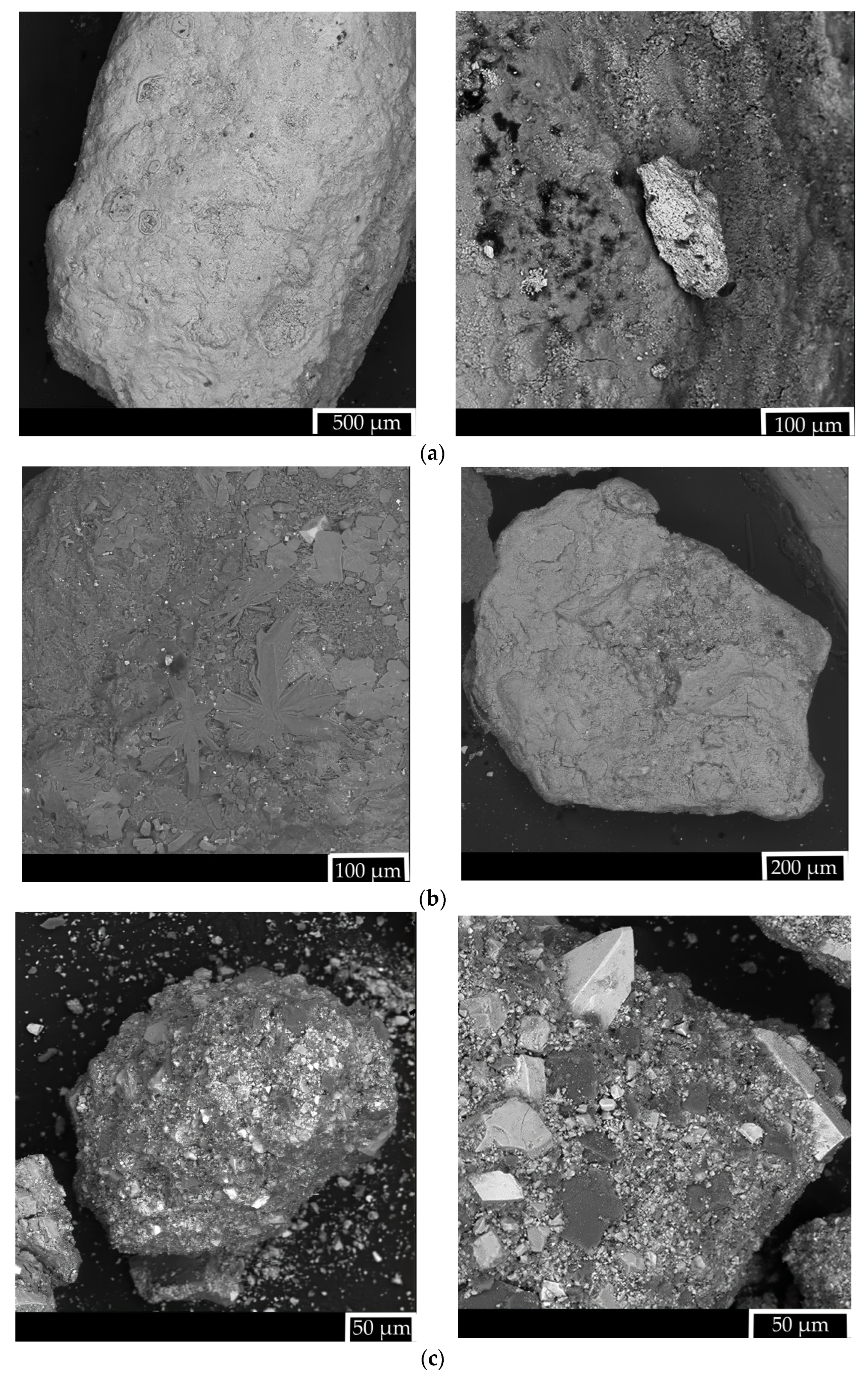
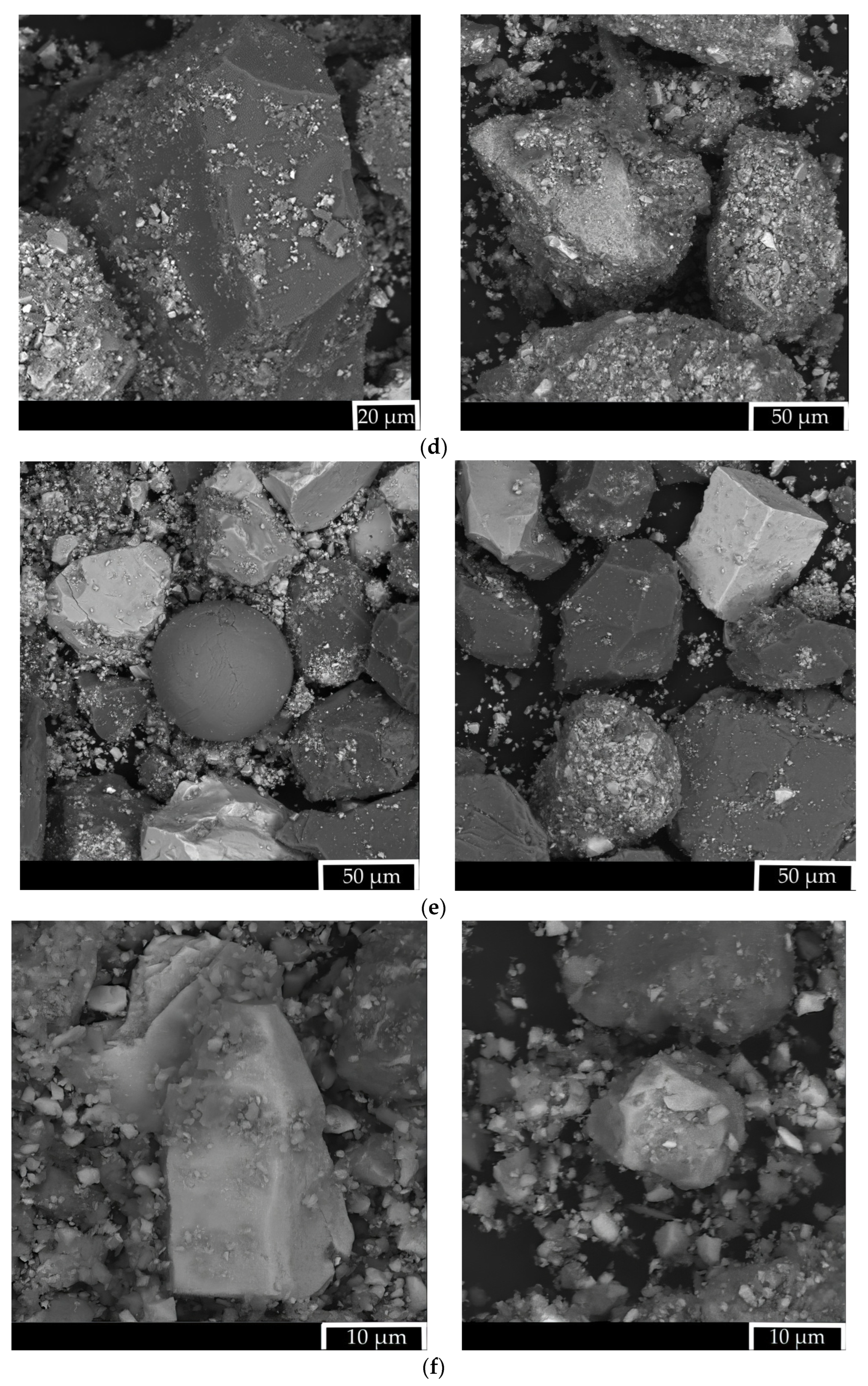
2.1. Characteristics of Research Objects
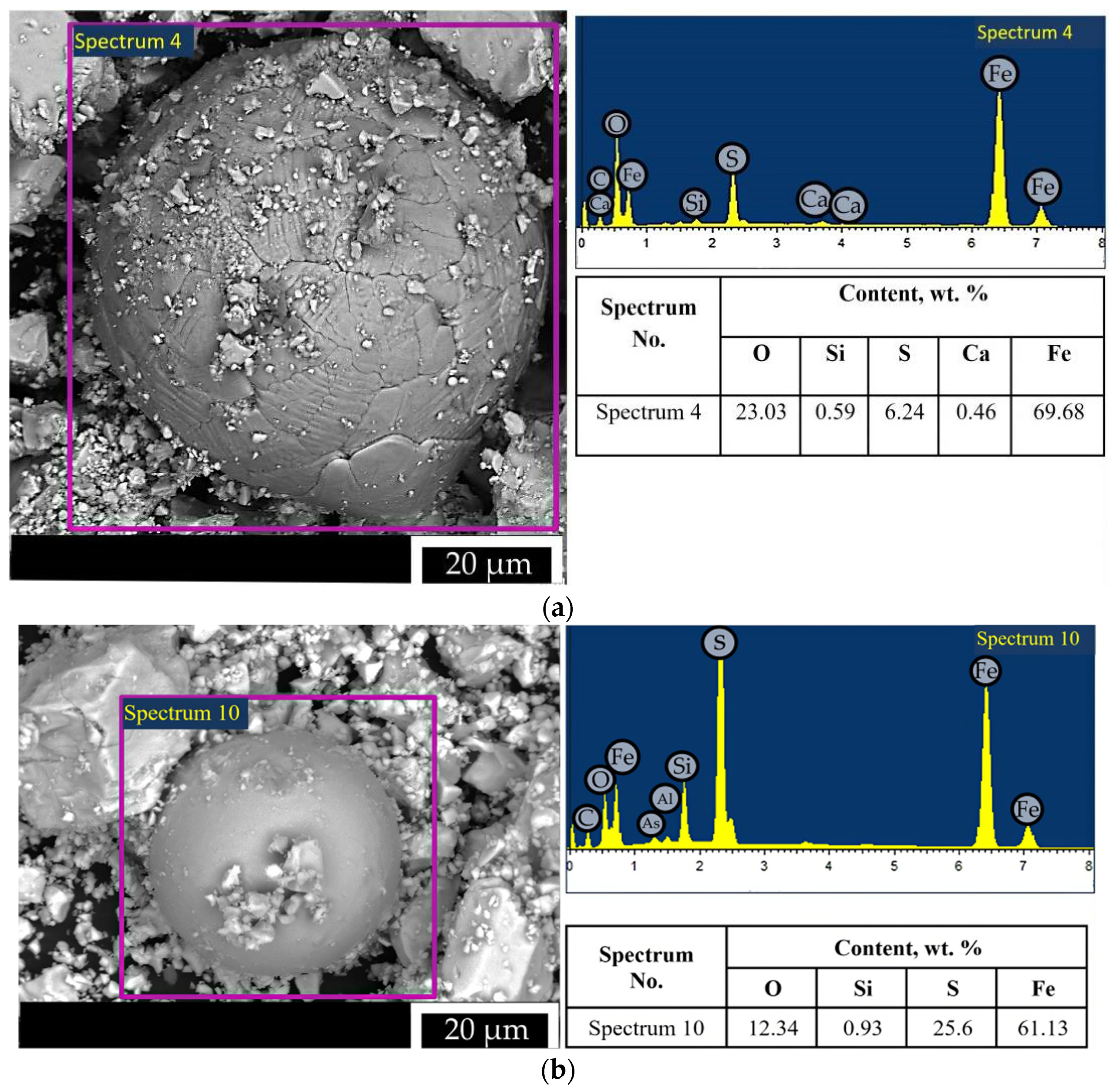
- Spheroids of various diameters formed as a result of the solidification of molten particles suspended in the flue gas stream (several types depending on the composition are fixed). It is established that in the fine class, there is a significant amount of particles smaller than 5 microns;
- unmelted and partially melted.
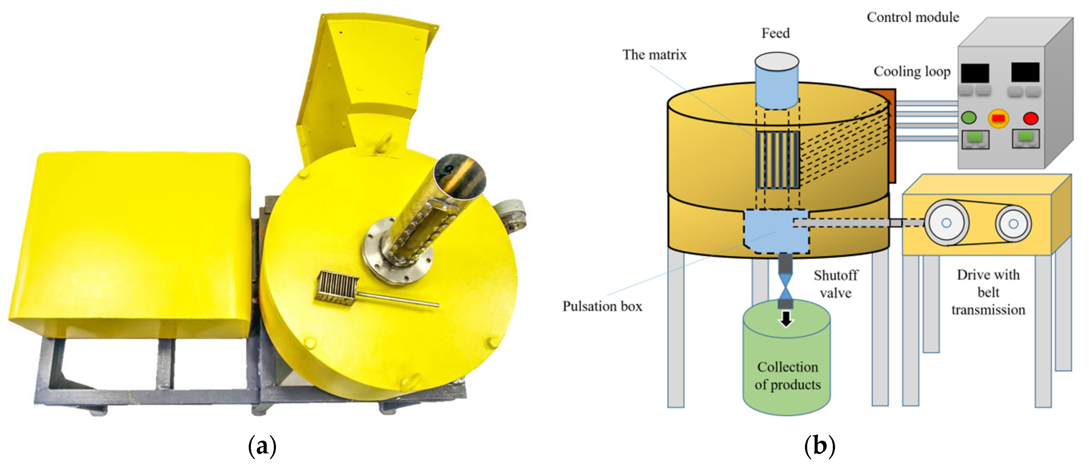
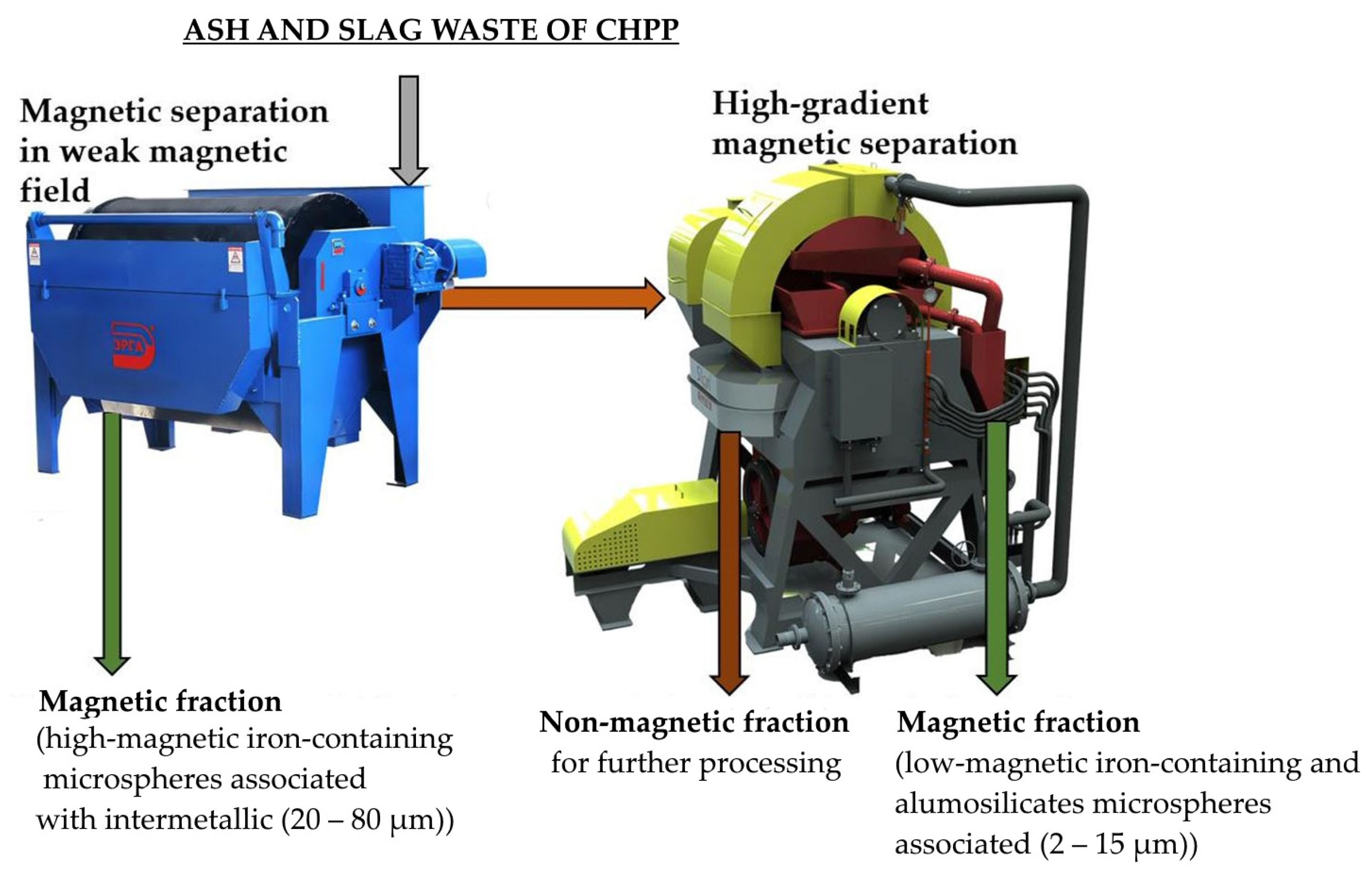
2.2. Magnetic Separation
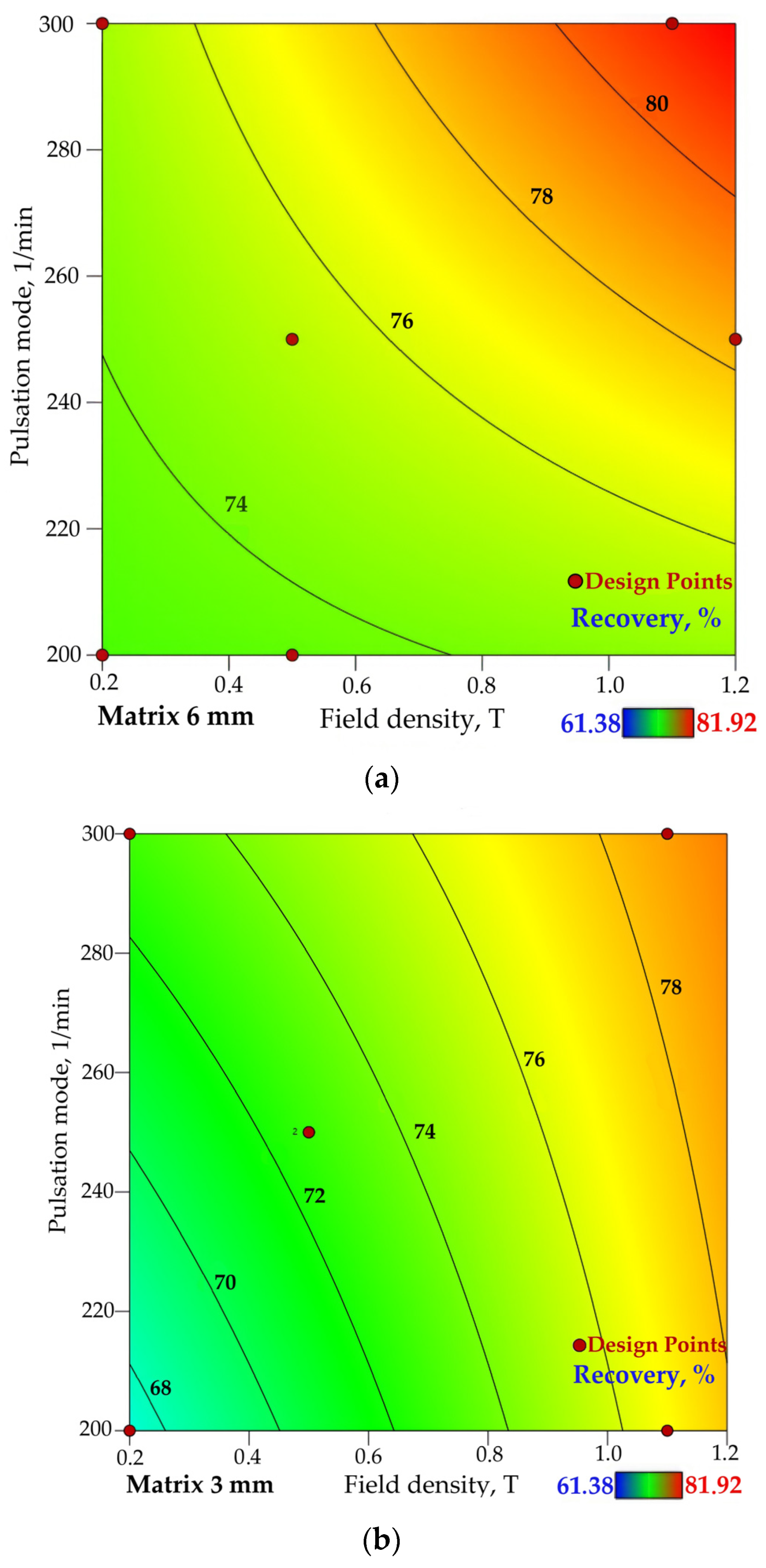
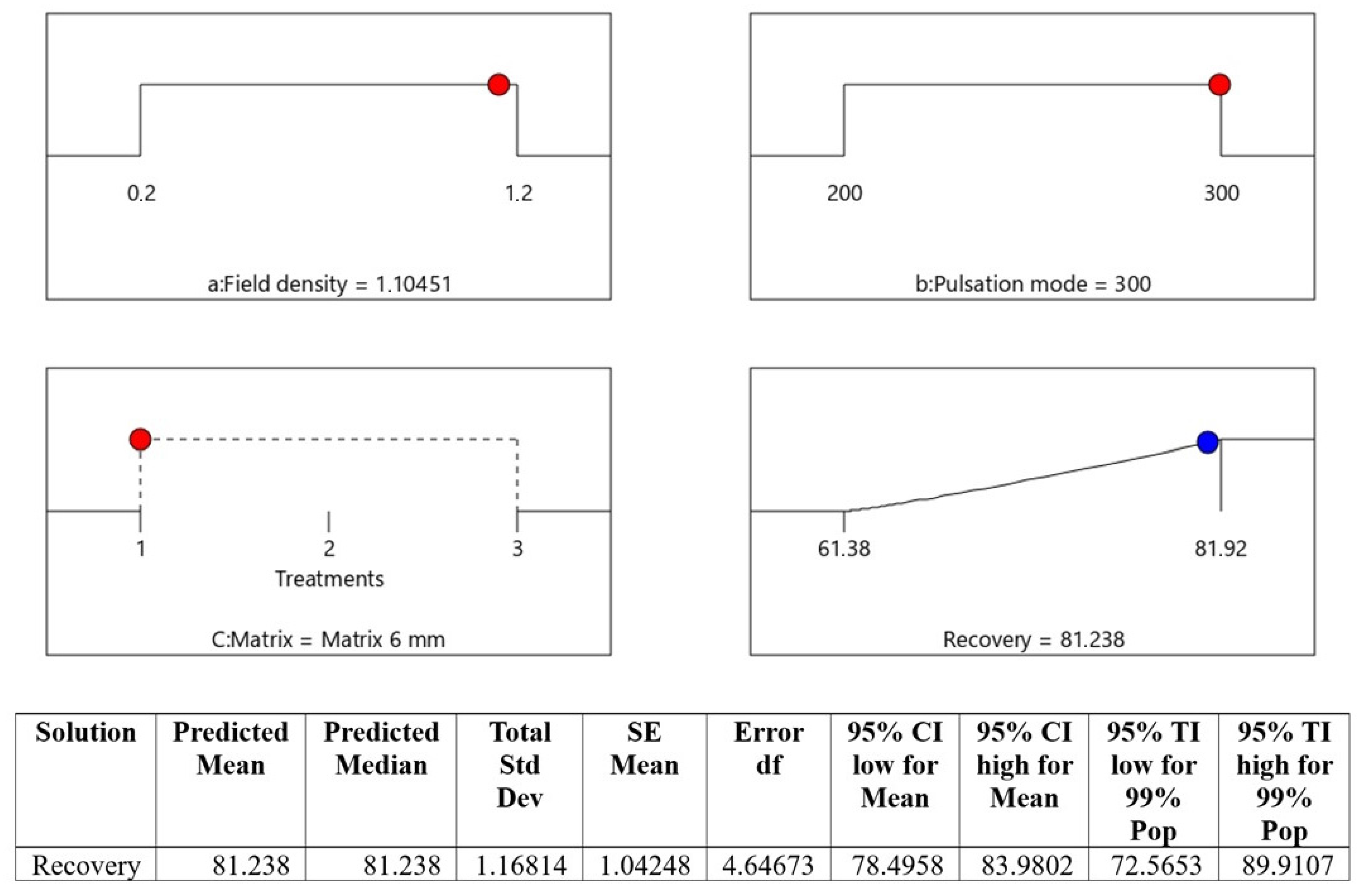
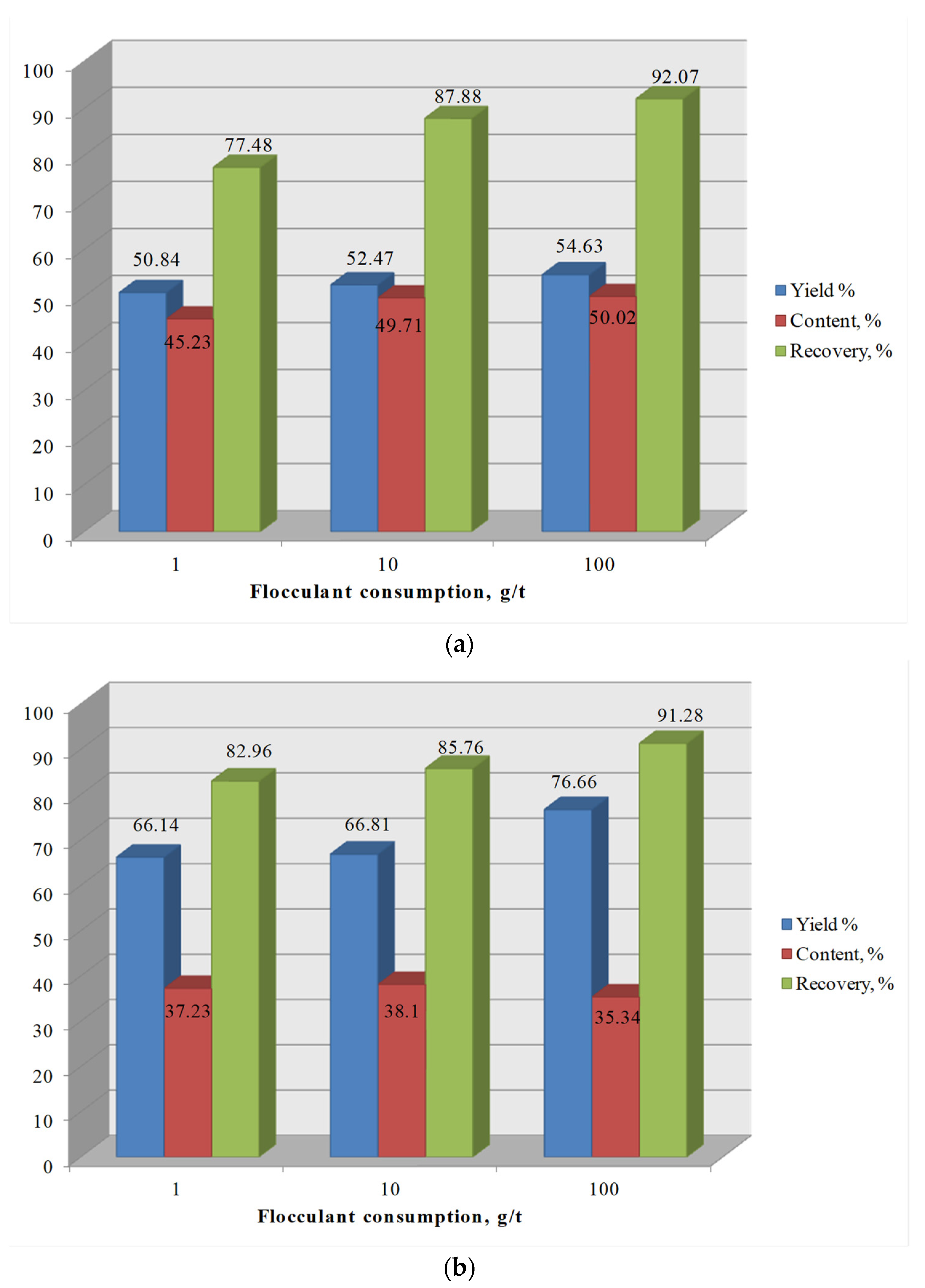
3. Results
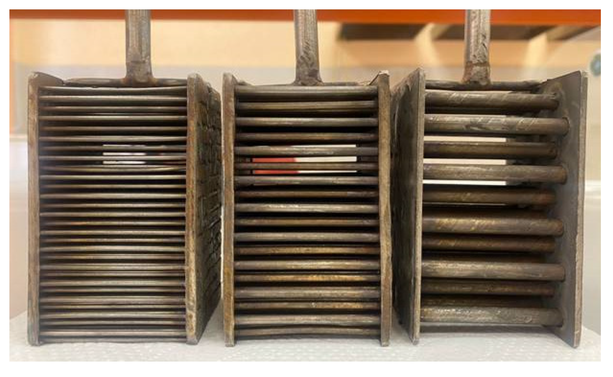
- -
- matrix rod diameter = 6 mm
- -
- matrix rod diameter = 3 mm
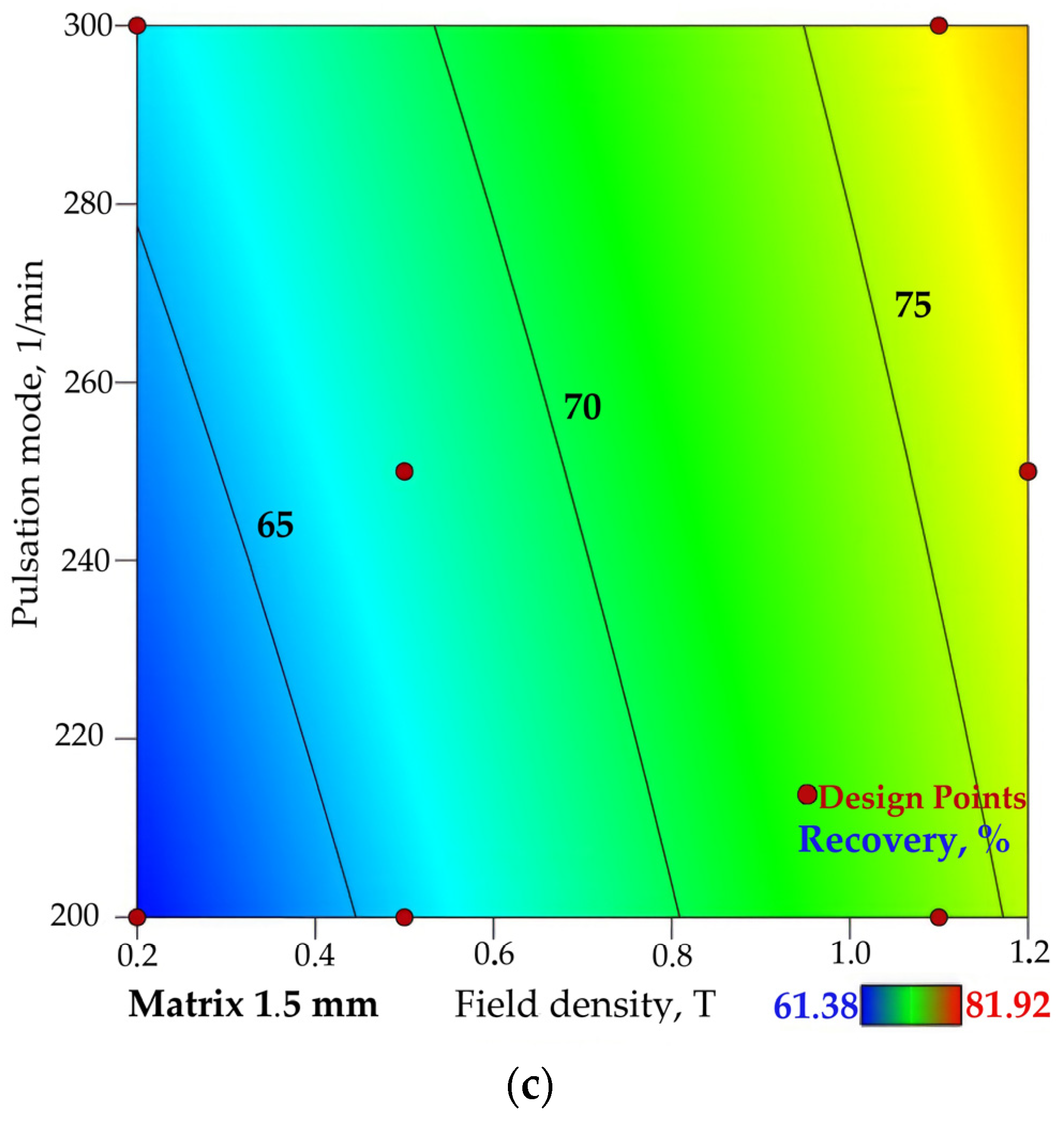
- -
- matrix rod diameter = 1.5 mm
4. Conclusions
Author Contributions
Funding
Data Availability Statement
Conflicts of Interest
References
- Meng, J.; Liao, W.; Zhang, G. Emerging CO2-Mineralization Technologies for Co-Utilization of Industrial Solid Waste and Carbon Resources in China. Minerals 2021, 11, 274. [Google Scholar] [CrossRef]
- Grigoryev, L.M.; Kheifets, E.A. Oil market: Conflict between recovery and energy transition. Vopr. Ekon. 2022, 9, 5–33. [Google Scholar] [CrossRef]
- Aleksandrova, T.; Nikolaeva, N.; Kuznetsov, V. Thermodynamic and Experimental Substantiation of the Possibility of Formation and Extraction of Organometallic Compounds as Indicators of Deep Naphthogenesis. Energies 2023, 16, 3862. [Google Scholar] [CrossRef]
- Nepsha, F.S.; Varnavskiy, K.A.; Voronin, V.A.; Zaslavskiy, L.S.; Liven, A.S. Integration of renewable energy at coal mining enterprises: Problems and prospects. J. Min. Inst. 2023, 261, 455–469. [Google Scholar]
- Dvoynikov, M.V.; Leusheva, E.L. Modern trends in hydrocarbon resources development. J. Min. Inst. 2022, 258, 879–880. [Google Scholar]
- Bazhin, V.Y.; Kuskov, V.B.; Kuskova, Y.V. Processing of low-demand coal and other carbon-containing materials for energy production purposes. Inz. Miner. 2019, 21, 195–198. [Google Scholar] [CrossRef]
- Shklyarskiy, Y.E.; Skamyin, A.N.; Jiménez Carrizosa, M. Energy efficiency in the mineral resources and raw materials complex. J. Min. Inst. 2023, 261, 323–324. [Google Scholar]
- Litvinenko, V.S.; Petrov, E.I.; Vasilevskaya, D.V.; Yakovenko, A.V.; Naumov, I.A.; Ratnikov, M.A. Assessment of the role of the state in the management of mineral resources. J. Min. Inst. 2022, 259, 95–111. [Google Scholar] [CrossRef]
- Litvinenko, V.S. Digital Economy as a Factor in the Technological Development of the Mineral Sector. Nat. Resour. Res. 2020, 29, 1521–1541. [Google Scholar] [CrossRef]
- Albalate, D.; Bel, G.; Teixidó, J.J. The Influence of Population Aging on Global Climate Policy. Popul. Environ. 2023, 45, 13. [Google Scholar] [CrossRef]
- Our World in Data. Available online: https://ourworldindata.org/electricity-mix (accessed on 19 November 2023).
- Plakitkin, Y.A.; Plakitkina, L.S.; Dyachenko, K.I. Coal as the basis of a great civilization leap and new opportunities for world development. Ugol’ 2022, 8, 77–83. [Google Scholar] [CrossRef]
- Chukaeva, M.A.; Matveeva, V.A.; Sverchkov, I.P. Complex processing of high-carbon ash and slag waste. J. Min. Inst. 2022, 253, 97–104. [Google Scholar] [CrossRef]
- Yatsenko, E.A.; Goltsman, B.M.; Trofimov, S.V.; Lazorenko, G.I. Processing of Ash and Slag Waste from Coal Fuel Combustion at CHPPs in the Arctic Zone of Russia with Obtaining Porous Geopolymer Materials. Therm. Eng. 2022, 69, 615–623. [Google Scholar] [CrossRef]
- Yatsenko, E.A.; Smolii, V.A.; Klimova, L.V.; Gol’tsman, B.M.; Ryabova, A.V.; Golovko, D.A.; Chumakov, A.A. Solid Fuel Combustion Wastes at CHPP in the Arctic Zone of the Russian Federation: Utility in Eco-Geopolymer Technology. Glass Ceram. 2022, 78, 374–377. [Google Scholar] [CrossRef]
- Marinina, O.; Nevskaya, M.; Jonek-Kowalska, I.; Wolniak, R.; Marinin, M. Recycling of Coal Fly Ash as an Example of an Efficient Circular Economy: A Stakeholder Approach. Energies 2021, 14, 3597. [Google Scholar] [CrossRef]
- Pukhov, S.A.; Kiseleva, S.P. Involvement in the economic turnover of ash and slag waste of thermal powerplants in the interests of eco-oriented economic development. Russ. J. Resour. Conserv. Recycl. 2020, 7, 10. (In Russian) [Google Scholar] [CrossRef]
- Dyk, J.C.V.; Benson, S.A.; Laumb, M.L.; Waanders, B. Coal and Coal Ash Characteristics to Understand Mineral Transformations and Slag Formation. Fuel 2009, 88, 1057–1063. [Google Scholar] [CrossRef]
- Uliasz-Bochenczyk, A.; Mokrzycki, E. Fly Ashes from Polish Power Plants and Combined Heat and Power Plants and Conditions of Their Application for Carbon Dioxide Utilization. Chem. Eng. Res. Des. 2006, 84, 837–842. [Google Scholar] [CrossRef]
- Basu, M.; Pande, M.; Bhadoria, P.B.S.; Mahapatra, S.C. Potential Fly-Ash Utilization in Agriculture: A Global Review. Prog. Nat. Sci. 2009, 19, 1173–1186. [Google Scholar] [CrossRef]
- Bhatt, A.; Priyadarshini, S.; Mohanakrishnan, A.A.; Abri, A.; Sattler, M.; Techapaphawit, S. Physical, Chemical, and Geotechnical Properties of Coal Fly Ash: A Global Review. Case Stud. Constr. Mater. 2019, 11, e00263. [Google Scholar] [CrossRef]
- Vereshchak, M.; Manakova, I.; Shokanov, A.; Sakhiyev, S. Mössbauer Studies of Narrow Fractions of Fly Ash Formed after Combustion of Ekibastuz Coal. Materials 2021, 14, 7473. [Google Scholar] [CrossRef] [PubMed]
- Ma, Z.; Shan, X.; Cheng, F. Distribution Characteristics of Valuable Elements, Al, Li, and Ga, and Rare Earth Elements in Feed Coal, Fly Ash, and Bottom Ash from a 300 MW Circulating Fluidized Bed Boiler. ACS Omega 2019, 4, 6854–6863. [Google Scholar] [CrossRef] [PubMed]
- Hu, X.; Huang, X.; Zhao, H.; Liu, F.; Wang, L.; Zhao, X.; Gao, P.; Li, X.; Ji, P. Possibility of Using Modified Fly Ash and Organic Fertilizers for Remediation of Heavy-Metal-Contaminated Soils. J. Clean. Prod. 2021, 284, 124713. [Google Scholar] [CrossRef]
- Loya, M.I.M.; Rawani, A.M. A review: Promising applications for utilization of fly ash. Int. J. Adv. Technol. Eng. Sci. 2014, 2, 143–149. [Google Scholar]
- Bazhin, V.Y.; Kuskov, V.B.; Kuskova, Y.V. Problems of using unclaimed coal and other carbon-containing materials as energy briquettes. Ugol 2019, 4, 50–54. [Google Scholar] [CrossRef]
- Huang, J.; Li, Z.; Chen, B.; Cui, S.; Lu, Z.; Dai, W.; Zhao, Y.; Duan, C.; Dong, L. Rapid detection of coal ash based on machine learning and X-ray fluorescence. J. Min. Inst. 2022, 256, 663–676. [Google Scholar] [CrossRef]
- Korchevenkov, S.A.; Aleksandrova, T.N. Preparation of Standard Iron Concentrates from Non-Traditional Forms of Raw Material Using a Pulsed Magnetic Field. Metallurgist 2017, 61, 375–381. [Google Scholar] [CrossRef]
- Svoboda, J.; Fujita, T. Recent Developments in Magnetic Methods of Material Separation. Miner. Eng. 2003, 16, 785–792. [Google Scholar] [CrossRef]
- Andronov, G.P.; Zakharova, I.B.; Filimonova, N.M.; L’vov, V.V.; Aleksandrova, T.N. Magnetic Separation of Eudialyte Ore under Pulp Pulsation. J. Min. Sci. 2016, 52, 1190–1194. [Google Scholar] [CrossRef]
- Fokina, S.B.; Petrov, G.V.; Sizyakova, E.V.; Andreev, Y.V.; Kozlovskaya, A.E. Process solutions of zinc-containing waste disposal in steel industry. Int. J. Civ. Eng. Technol. 2019, 10, 2083–2089. [Google Scholar]
- Kairakbaev, A.K.; Abdrakhimov, V.Z.; Abdrakhimova, E.S. The use of ash material of east Kazakhstan in the production of porous aggregate on the basis of liquid-glass compositions. Ugol’ 2019, 1, 70–73. [Google Scholar] [CrossRef]
- Lan, M.; He, Z.; Hu, X. Optimization of Iron Recovery from BOF Slag by Oxidation and Magnetic Separation. Metals 2022, 12, 742. [Google Scholar] [CrossRef]
- Petropavlovskaya, V.; Zavadko, M.; Novichenkova, T.; Petropavlovskii, K.; Sulman, M. The Use of Aluminosilicate Ash Microspheres from Waste Ash and Slag Mixtures in Gypsum-Lime Compositions. Materials 2023, 16, 4213. [Google Scholar] [CrossRef] [PubMed]
- Valeev, D.; Kunilova, I.; Alpatov, A.; Varnavskaya, A.; Ju, D. Magnetite and Carbon Extraction from Coal Fly Ash Using Magnetic Separation and Flotation Methods. Minerals 2019, 9, 320. [Google Scholar] [CrossRef]
- Li, W.; Han, Y.; Xu, R.; Gong, E. A Preliminary Investigation into Separating Performance and Magnetic Field Characteristic Analysis Based on a Novel Matrix. Minerals 2018, 8, 94. [Google Scholar] [CrossRef]
- Chen, L.; Xiong, D.; Huang, H. Pulsating High-Gradient Magnetic Separation of Fine Hematite from Tailings. Min. Metall. Explor. 2009, 26, 163–168. [Google Scholar] [CrossRef]
- Luo, L.; Zhang, J.; Yu, Y. Recovering Limonite from Australia Iron Ores by Flocculation-High Intensity Magnetic Separation. J. Cent. South Univ. Technol. 2005, 12, 682–687. [Google Scholar] [CrossRef]
- Wills, B.A.; Napier-Munn, T.J. Mineral Processing Technology, 7th ed.; Elsevier Science & Technology Books: Amsterdam, The Netherlands, 2006. [Google Scholar]
- Chanturia, V.A.; Minenko, V.G.; Samusev, A.L.; Koporulina, E.V.; Kozhevnikov, G.A. Stimulation of Leaching of Rare Earth Elements from Ash and Slag by Energy Impacts. J. Min. Sci. 2022, 58, 278–288. [Google Scholar] [CrossRef]
- Chen, L.; Qian, Z.; Wen, S.; Huang, S. High-gradient magnetic separation of ultrafine particles with rod matrix. Miner. Process. Extr. Metall. Rev. 2013, 34, 340–347. [Google Scholar] [CrossRef]
- Jin, J.X.; Liu, H.K.; Zeng, R.; Dou, S.X. Developing a HTS Magnet for High Gradient Magnetic Separation Techniques. Phys. C Supercond. 2000, 341–348, 2611–2612. [Google Scholar] [CrossRef]
- Xiong, D.; Liu, S.; Chen, J. New Technology of Pulsating High Gradient Magnetic Separation. Int. J. Miner. Process. 1998, 54, 111–127. [Google Scholar] [CrossRef]
- Bessais, L. Structure and Magnetic Properties of Intermetallic Rare-Earth-Transition-Metal Compounds: A Review. Materials 2022, 15, 201. [Google Scholar] [CrossRef] [PubMed]
- Ding, L.; Chen, L.; Zeng, J. Investigation of Combination of Variable Diameter Rod Elements in Rod Matrix on High Gradient Magnetic Separation Performance. Adv. Mater. Res. 2014, 1030, 1193–1196. [Google Scholar] [CrossRef]
- Song, S.; Lopez-Valdivieso, A.; Ding, Y. Effects of Nonpolar Oil on Hydrophobic Flocculation of Hematite and Rhodochrosite Fines. Powder Technol. 1999, 101, 73–80. [Google Scholar] [CrossRef]
- Su, T.; Chen, T.; Zhang, Y.; Hu, P. Selective Flocculation Enhanced Magnetic Separation of Ultrafine Disseminated Magnetite Ores. Minerals 2016, 6, 86. [Google Scholar] [CrossRef]
- Drozhzhin, V.S.; Shpirt, M.Y.; Danilin, L.D.; Kuvaev, M.D.; Pikulin, I.V.; Potemkin, G.A.; Redyushev, S.A. Formation processes and main properties of hollow aluminosilicate microspheres in fly ash from thermal power stations. Solid Fuel Chem. 2008, 42, 107–119. [Google Scholar] [CrossRef]
- Xiong, T.; Ren, X.; Xie, M.; Rao, Y.; Peng, Y.; Chen, L. Recovery of Ultra-Fine Tungsten and Tin from Slimes Using Large-Scale SLon-2400 Centrifugal Separator. Minerals 2020, 10, 694. [Google Scholar] [CrossRef]


| Size Class, mm | Yield, % | Content, % | ||||||||||||
|---|---|---|---|---|---|---|---|---|---|---|---|---|---|---|
| Fe | Si | S | As | Al | Ca | Sb | K | Mn | Zn | Cu | Ni | Sr | ||
| +0.800 | 0.13 | 31.55 | 16.23 | 3.53 | 2.75 | 1.17 | 2.18 | 1.03 | 0.81 | 0.14 | 0.076 | 0.069 | 0.034 | 0.011 |
| −0.800 + 0.425 | 0.14 | 30.82 | 15.84 | 3.24 | 3.05 | 1.44 | 3.19 | 1.41 | 1.02 | 0.18 | 0.073 | 0.121 | 0.039 | 0.014 |
| −0.425 + 0.212 | 1.16 | 29.35 | 16.43 | 2.58 | 3.38 | 1.65 | 3.48 | 2.22 | 0.77 | 0.18 | 0.076 | 0.068 | 0.038 | 0.013 |
| −0.212 + 0.106 | 0.80 | 28.52 | 15.85 | 2.89 | 2.77 | 2.32 | 3.94 | 1.88 | 1.10 | 0.18 | 0.073 | 0.069 | 0.033 | 0.014 |
| −0.106 + 0.045 | 4.40 | 23.79 | 16.85 | 6.33 | 3.07 | 2.28 | 1.84 | 0.82 | 1.78 | 0.13 | 0.049 | 0.047 | 0.021 | 0.010 |
| −0.045 + 0 | 93.37 | 29.97 | 15.80 | 2.45 | 3.44 | 2.31 | 3.37 | 2.02 | 0.83 | 0.19 | 0.074 | 0.074 | 0.037 | 0.012 |
| Total | 100 | 29.68 | 15.85 | 2.63 | 3.42 | 2.30 | 3.31 | 1.97 | 0.87 | 0.19 | 0.07 | 0.073 | 0.036 | 0.012 |
| Product | Yield, % | Fe | Si | S | As | Al | Ca | Sb | K | Mn | Zn | Cu | Ni | Sr |
|---|---|---|---|---|---|---|---|---|---|---|---|---|---|---|
| Content, % | ||||||||||||||
| Magnetic fraction (1 A) | 1.04 | 29.55 | 16.23 | 2.53 | 2.75 | 1.17 | 2.18 | 1.03 | 0.81 | 0.14 | 0.076 | 0.069 | 0.034 | 0.011 |
| Magnetic fraction (2 A) | 4.32 | 32.82 | 15.84 | 3.29 | 3.05 | 1.44 | 3.19 | 1.41 | 1.02 | 0.21 | 0.073 | 0.121 | 0.039 | 0.014 |
| Magnetic fraction (3 A) | 2.02 | 33.65 | 16.43 | 2.58 | 3.38 | 1.61 | 3.48 | 2.22 | 0.77 | 0.25 | 0.071 | 0.068 | 0.038 | 0.013 |
| Magnetic fraction (4 A) | 3.68 | 30.52 | 15.85 | 2.89 | 2.77 | 2.32 | 3.94 | 1.88 | 1.05 | 0.19 | 0.073 | 0.069 | 0.033 | 0.014 |
| Magnetic fraction (5 A) | 4.96 | 23.79 | 16.87 | 4.17 | 3.07 | 2.28 | 1.84 | 0.82 | 1.75 | 0.13 | 0.049 | 0.047 | 0.021 | 0.01 |
| Magnetic fraction (6 A) | 12.6 | 28.41 | 14.59 | 3.13 | 3.21 | 1.94 | 2.06 | 1.61 | 0.84 | 0.17 | 0.084 | 0.08 | 0.032 | 0 |
| Non-magnetic fraction | 71.38 | 29.97 | 15.98 | 2.38 | 3.55 | 2.45 | 3.62 | 2.16 | 0.8 | 0.19 | 0.073 | 0.071 | 0.037 | 0.014 |
| Total: | 100 | 29.68 | 15.85 | 2.63 | 3.42 | 2.30 | 3.31 | 1.97 | 0.87 | 0.19 | 0.07 | 0.073 | 0.036 | 0.012 |
| Product | Yield, % | Recovery, % | ||||||||||||
| Magnetic fraction (1 A) | 1.04 | 1.035 | 1.065 | 1.002 | 0.836 | 0.529 | 0.685 | 0.543 | 0.968 | 0.783 | 1.080 | 0.984 | 0.996 | 0.954 |
| Magnetic fraction (2 A) | 4.32 | 4.777 | 4.317 | 5.410 | 3.851 | 2.706 | 4.163 | 3.090 | 5.063 | 4.876 | 4.309 | 7.166 | 4.745 | 5.046 |
| Magnetic fraction (3 A) | 2.02 | 2.290 | 2.094 | 1.984 | 1.996 | 1.415 | 2.123 | 2.275 | 1.787 | 2.714 | 1.960 | 1.883 | 2.162 | 2.191 |
| Magnetic fraction (4 A) | 3.68 | 3.784 | 3.680 | 4.048 | 2.979 | 3.714 | 4.380 | 3.510 | 4.440 | 3.758 | 3.671 | 3.481 | 3.420 | 4.298 |
| Magnetic fraction (5 A) | 4.96 | 3.976 | 5.279 | 7.873 | 4.451 | 4.920 | 2.757 | 2.064 | 9.973 | 3.466 | 3.321 | 3.196 | 2.934 | 4.138 |
| Magnetic fraction (6 A) | 12.6 | 12.061 | 11.598 | 15.013 | 11.822 | 10.634 | 7.840 | 10.292 | 12.160 | 11.512 | 14.462 | 13.818 | 11.356 | 0.000 |
| Non-magnetic fraction | 71.38 | 72.077 | 71.966 | 64.669 | 74.065 | 76.081 | 78.052 | 78.225 | 65.609 | 72.892 | 71.198 | 69.473 | 74.386 | 83.373 |
| Total: | 100 | 100 | 100 | 100 | 100 | 100 | 100 | 100 | 100 | 100 | 100 | 100 | 100 | 100 |
| Factor 1 | Factor 2 | Factor 3 | Response 1 | ||
|---|---|---|---|---|---|
| Group | Run | a: Field Density | b: Pulsation Mode | C: Matrix | Recovery |
| T | 1/min | % | |||
| 1 | 1 | 0.2 | 200 | Matrix 6 mm | 71.82 |
| 1 | 2 | 0.2 | 200 | Matrix 3 mm | 66,81 |
| 1 | 3 | 0.2 | 200 | Matrix 1.5 mm | 61.38 |
| 2 | 4 | 1.1 | 200 | Matrix 3 mm | 76.81 |
| 2 | 5 | 1.1 | 200 | Matrix 1.5 mm | 74.52 |
| 3 | 6 | 1.2 | 250 | Matrix 6 mm | 77.04 |
| 3 | 7 | 1.2 | 250 | Matrix 1.5 mm | 75.62 |
| 4 | 8 | 0.2 | 300 | Matrix 3 mm | 72.47 |
| 4 | 9 | 0.2 | 300 | Matrix 6 mm | 74.69 |
| 4 | 10 | 0.2 | 300 | Matrix 1.5 mm | 65.03 |
| 5 | 11 | 1.1 | 300 | Matrix 6 mm | 81.92 |
| 5 | 12 | 1.1 | 300 | Matrix 3 mm | 78.79 |
| 5 | 13 | 1.1 | 300 | Matrix 1.5 mm | 76.99 |
| 6 | 14 | 0.5 | 250 | Matrix 1.5 mm | 70.23 |
| 6 | 15 | 0.5 | 250 | Matrix 3 mm | 73.51 |
| 7 | 16 | 0.5 | 200 | Matrix 6 mm | 75.11 |
| 7 | 17 | 0.5 | 200 | Matrix 1.5 mm | 64.68 |
| 8 | 18 | 0.5 | 250 | Matrix 3 mm | 73.29 |
| 8 | 19 | 0.5 | 250 | Matrix 6 mm | 75.23 |
| Source | Term df | Error df | F-Value | p-Value | |
|---|---|---|---|---|---|
| Whole-plot | 3 | 2.95 | 24.14 | 0.0140 | significant |
| a-Field density | 1 | 3.24 | 53.50 | 0.0040 | |
| b-Pulsation mode | 1 | 3.28 | 10.25 | 0.0436 | |
| ab | 1 | 3.15 | 0.0015 | 0.9713 | |
| Subplot | 8 | 3.65 | 11.51 | 0.0208 | significant |
| C-Matrix | 2 | 4.29 | 26.06 | 0.0040 | |
| aC | 2 | 4.10 | 8.00 | 0.0385 | |
| bC | 2 | 4.02 | 0.0934 | 0.9127 | |
| abC | 2 | 3.86 | 1.23 | 0.3855 |
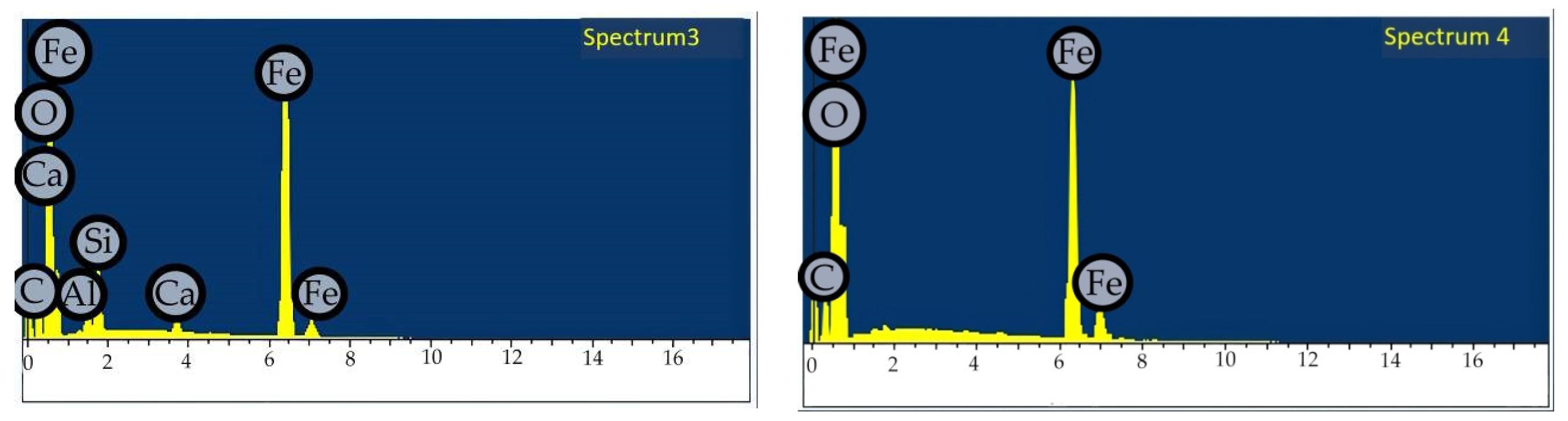
| Content, wt. % | |||||
|---|---|---|---|---|---|
| O | Al | Si | Ca | Fe | |
| Spectrum 1 | 32.34 | 9.2 | 21.31 | 3.13 | 34.02 |
| Spectrum 2 | 30.83 | 6.62 | 16.91 | 2.2 | 43.44 |
| Spectrum 3 | 33.05 | 9.84 | 16.17 | 0.85 | 40.09 |
| Spectrum 4 | 30.12 | 69.88 | |||
Disclaimer/Publisher’s Note: The statements, opinions and data contained in all publications are solely those of the individual author(s) and contributor(s) and not of MDPI and/or the editor(s). MDPI and/or the editor(s) disclaim responsibility for any injury to people or property resulting from any ideas, methods, instructions or products referred to in the content. |
© 2024 by the authors. Licensee MDPI, Basel, Switzerland. This article is an open access article distributed under the terms and conditions of the Creative Commons Attribution (CC BY) license (https://creativecommons.org/licenses/by/4.0/).
Share and Cite
Aleksandrova, T.; Nikolaeva, N.; Afanasova, A.; Chenlong, D.; Romashev, A.; Aburova, V.; Prokhorova, E. Increase in Recovery Efficiency of Iron-Containing Components from Ash and Slag Material (Coal Combustion Waste) by Magnetic Separation. Minerals 2024, 14, 136. https://doi.org/10.3390/min14020136
Aleksandrova T, Nikolaeva N, Afanasova A, Chenlong D, Romashev A, Aburova V, Prokhorova E. Increase in Recovery Efficiency of Iron-Containing Components from Ash and Slag Material (Coal Combustion Waste) by Magnetic Separation. Minerals. 2024; 14(2):136. https://doi.org/10.3390/min14020136
Chicago/Turabian StyleAleksandrova, Tatiana, Nadezhda Nikolaeva, Anastasia Afanasova, Duan Chenlong, Artyem Romashev, Valeriya Aburova, and Evgeniya Prokhorova. 2024. "Increase in Recovery Efficiency of Iron-Containing Components from Ash and Slag Material (Coal Combustion Waste) by Magnetic Separation" Minerals 14, no. 2: 136. https://doi.org/10.3390/min14020136
APA StyleAleksandrova, T., Nikolaeva, N., Afanasova, A., Chenlong, D., Romashev, A., Aburova, V., & Prokhorova, E. (2024). Increase in Recovery Efficiency of Iron-Containing Components from Ash and Slag Material (Coal Combustion Waste) by Magnetic Separation. Minerals, 14(2), 136. https://doi.org/10.3390/min14020136