Article

Polypropylene Fiber Effect on Flexural Strength, Toughness, Deflection, Failure Mode and Microanalysis of Cementitious Backfills under Three-Point Bending Conditions

1
State Key Laboratory of High-Efficient Mining and Safety of Metal Mines of Ministry of Education, University of Science and Technology Beijing, Beijing 100083, China
2
School of Civil and Resource Engineering, University of Science and Technology Beijing, Beijing 100083, China
3
Department of Civil Engineering, Geotechnical Division, Recep Tayyip Erdogan University, Fener, Rize TR53100, Türkiye
*
Authors to whom correspondence should be addressed.
Minerals 2023, 13(9), 1135; https://doi.org/10.3390/min13091135
Submission received: 12 July 2023 / Revised: 11 August 2023 / Accepted: 17 August 2023 / Published: 28 August 2023
(This article belongs to the Special Issue Cemented Mine Waste Backfill: Experiment and Modelling)

Abstract

:
Cemented tailings backfill (CTB) is continually practiced in a large number of metallic mines for re-filling underground ore extraction areas. Re-filling these areas can boost the security of mining teams during construction. Hence, CTB’s durability/ductility is extremely vital to ensure the safety of the entire mine. In this study, layered-fiber-reinforced CTB (LFR-CTB) was manufactured using polypropylene fiber (PPF) to increase the strength and flexibility of backfilling. The strength and bending features of CTB and LFR-CTB specimens were explored through a three-point bending test and SEM microanalysis. Test findings pointed out that the flexural strength of 14-day-cured CTB specimens without fiber delamination and with cement showed that a tailings ratio of 1:4 was the largest among others. Residual flexural strength of LFR-CTB was greater than those of CTB without fiber delamination. Accumulating fiber delamination effectively improved CTB’s flexural features. CTBs without fiber delamination presented the largest average flexural modulus values. LFR-CTBs presented greater average toughness index values than ordinary CTB specimens. Adding fiber facilitated the progress of CTB’s post-peak rigidity. LFR-CTBs containing high-fiber delamination dimensional height have excellent bending properties. The damage mode of all backfill specimens is chiefly tensile damage. The overall bonding of LFR-CTB specimens in the presence of interlayer interfaces is outstanding, not affecting their bending performance. Ettringite and CSH gels were found to be key hydration materials. The addition of fiber to the filling has an inhibitory impact on the extension of the cracks occurring within specimens. Finally, this study’s key consequence is to deliver a technical guideline and reference in order to reveal LFR-CTB’s enhancement and delamination mechanism for industrial applications.

1. Introduction

Underground mining is a principal method used to extract metallic and nonmetallic ores [1]. The application of underground mining offers significant economic benefits compared to open pit mining [2,3]. Implementing these mining techniques inevitably creates a large amount of tailings, which poses challenges [4], waste rock [5], and others [6], which inevitably pile onto the surface and cause serious destruction to nearby natural environment [7]. In response to large amounts of surface waste storage [8], researchers and field workers jointly study the use of the cementitious paste/tailings backfill (CPB/CTB; [9,10,11]) method to further treat underground mining extraction areas [12].
Applying CTB technology not only improves the safety of mining operations [13,14], but also reduces the accumulation of surface mining waste, which corresponds to the green growth concept, fostering economic growth and development [15,16,17]. Similarly, the application of the CTB system allows mining firms to better manage the waste generated by underground mining as backfill [18]. Usually, CTB/CPB is prepared from cementitious materials, tailings, and mixing water [19]. For the study of CTB’s strength characteristics, numerous researchers have conducted some tests, covering uniaxial/triaxial compressive strength [20,21,22] and flexural/tensile strength [23,24,25]. Orebody recovery work under CTB is difficult due to the high brittleness and poor bending features of filling [26]. The quality of CTB materials is one of the principal factors governing the application of CTB technology in modern mines [27].
CTB is less tough, which is very unfavorable for underground orebody recovery in terms of engineering applications [28,29]. In backfill mining methods, CTB’s poor strength characteristics pose a significant threat to the protection of mine operators and equipment [30]. Many scholars and engineers have so far performed numerous investigations on CTB’s toughness improvement [31,32]. The main method to enhance the toughness of CTB materials is to incorporate different additives such as straw [33], rubber [34], fiber [32], sand [35], and others [36,37]. Researchers have improved the crack resistance and toughness of engineering specimens by adding hybrid fibers to CTB (i.e., strengthening fill’s strength features and enhancing the material’s stress–crack rupture link, [38,39,40]). The use of fibers within CTB enhances its ductility behavior [41]. Additionally, the use of fibers can replace most of the cement material, thereby reducing the costs associated with cement [42] and improve the utilization of tailings [43]. For the evaluation of the crack resistance of a specimen, the flexural strength is a more important evaluation index [44]. The flexural strength can evaluate the cracking resistance and cracking characteristics of a specimen [45], and reflect the link between internal stress and the crack expansion of filling material [46]. The researchers also found that cement characteristics [47], water-to-solid ratio [48], cement/tailings ratio [49], and fiber type/content [50] influenced the flexural deformation features of filling specimens. Thus, it is very important to choose reasonable cement and fiber and set a reasonable water/solid ratio as well as a cement/tailings ratio [51,52]. Some studies have also shown that accumulating fiber in the backfill can well enhance cementitious materials’ durability [53] and that the properties of fiber material itself affect the backfill’s suitability [54].
To better explore fiber-reinforced CTB’s mechanical mechanisms, a large number of researchers have undertaken diverse laboratory tests on backfill specimens [55,56,57]. Some researchers [58,59] experimentally inspected that CTB’s strength features were governed by the fibers mainly in terms of their type and length. Chen et al. [60] established that polybutylene fibers could vividly enhance CTB’s strength, ductility, and stability. Li et al. [61] explored the mechanisms governing the kinetic behavior of the CTB reinforced with high-performance fiber. Some studies have also shown that adding an excessive amount of fibers to the backfill mix increases its porosity [62,63]. Certainly, an increase in the porosity directly affects the mechanical behavior of filling specimens [64].
In the existing research on the mechanical features of backfills integrating with fiber reinforcement, many researchers mainly focus on the characteristics of physical properties such as fiber type and length as the main direction for a comprehensive analysis of the factors governing a backfill’s strength behavior. Little has been said about the mechanisms affecting the strength behavior of LFR-CTB specimens. Consequently, this study intends to create LFR-CTB specimens by using polypropylene fibers and investigate the flexural strength, toughness index, fracture mode, crack distribution extension, hydration products, and element distribution of LFR-CTB specimens by means of a three-point bending test and SEM microanalysis.

2. Materials and Methods
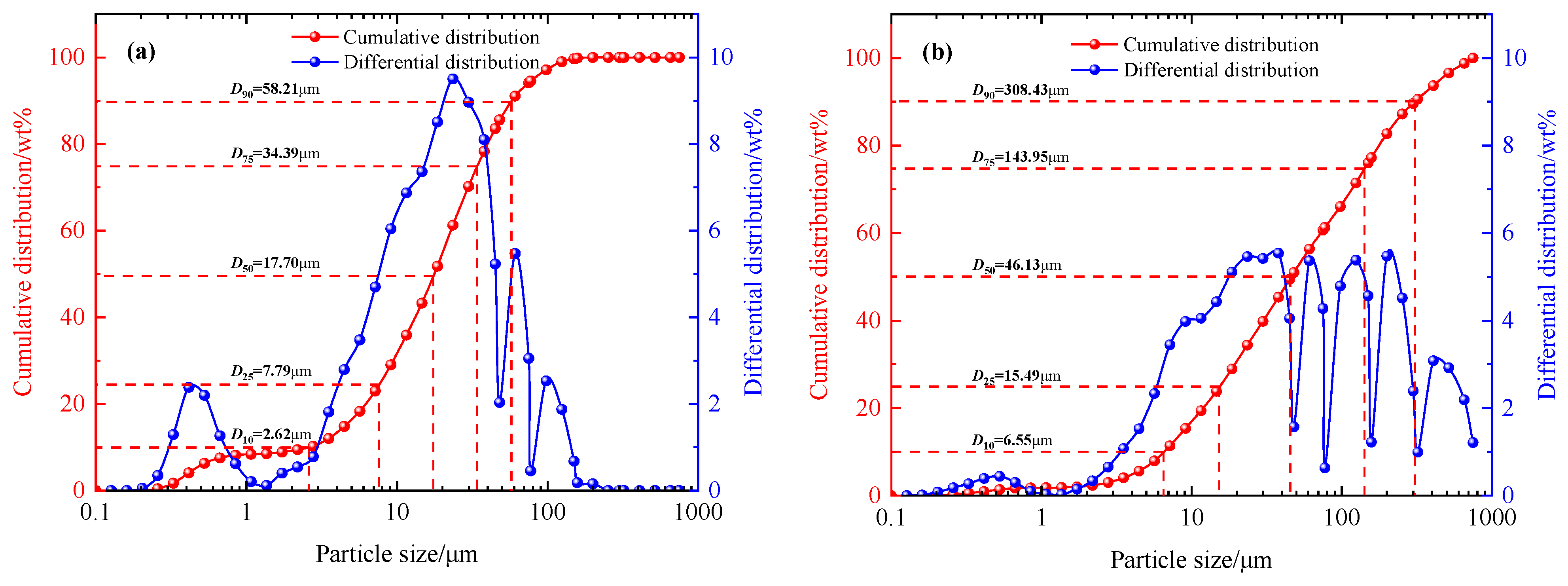
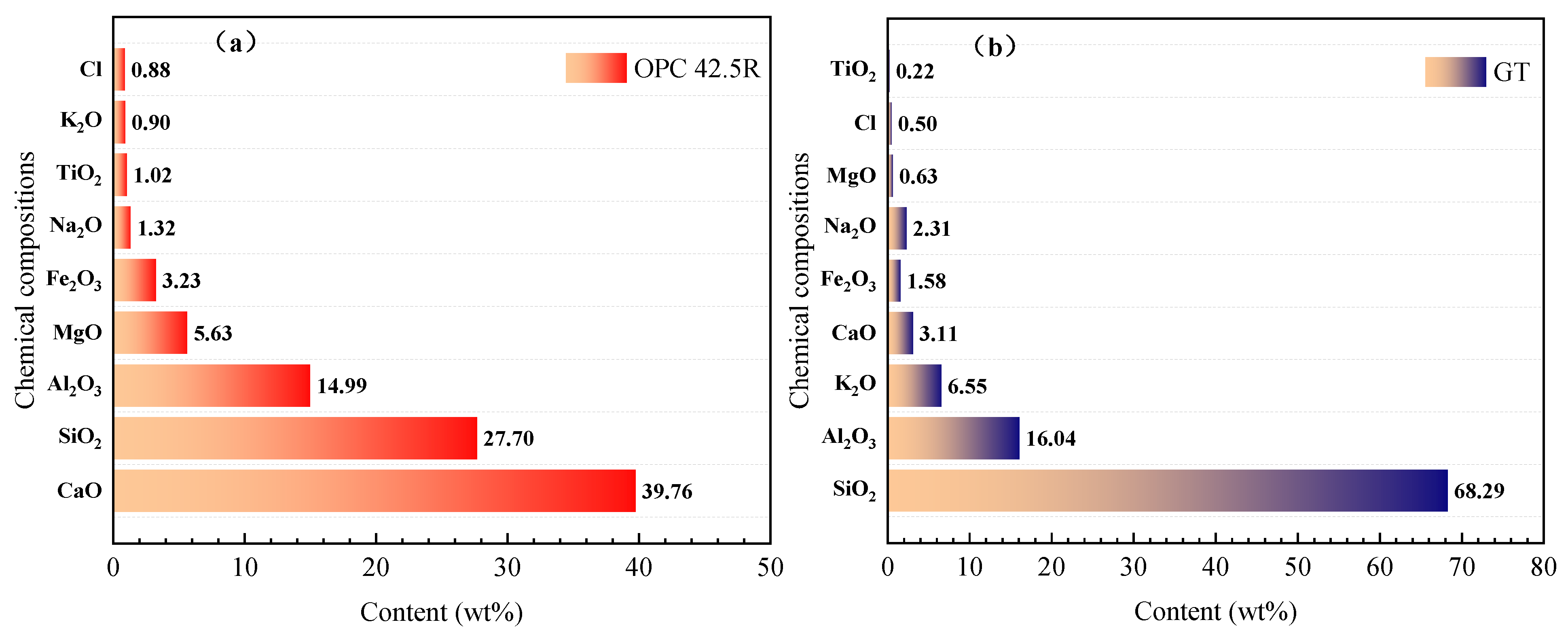
2.1. Basic Elements

The gold tailings (GTs) obtained from a Chinese underground mining company was used as a principal product to manufacture filling specimens. Ordinary Portland cement (OPC) type 42.5R, supplied from a cement factory located in the province of Shandong, China, was selected as a key cementitious material. Note that R designates high-strength cement and 42.5 designates a compressive strength value of 42.5 MPa reached after curing for 28 days. In addition, grain size distribution (PSD) of GTs and cement products was analyzed by a laser grain sizer (LSPOP) in wet conditions. Before measuring GTs’ grain sizes, it is important to note that the main requirement of this instrumental device is that the tested GTs material must be dry without containing any moisture. Figure 1 demonstrates the specific grain sizes of GTs and cement products.
The mean particle diameter D50 and the specific surface area value are 46.13 m, and 595.817 m2/kg, respectively. Based on the test results of Qiu et al. [65], one can notice that the D50 value of GTs in the range of 2–53 µm is assessed as powder particles.
Similarly, an XRF-1800 device was selected to study GTs/cement’s chemical structure. Figure 2 indicates the XRF results. All experimental conditions were considered as follows: scan rapidity of the instrument set to 300°/min and the voltage and current parameters were adjusted to 60 kV and 140 mA. The analysis results showed that SiO2 and Al2O3 were the main oxides of GTs, accounting for 84.33% of the total mass of the tailings. SiO2, Al2O3, and CaO are the major oxides of OPC 42.5R, representing 82.45% of the total mass of OPC 42.5R.
Ordinary tap water was also chosen to consistently blend CTB’s solid components such as tailings and cement, ignoring the chemical composition impact of mixing water on the strength features of CTB and LFR-CTB specimens.

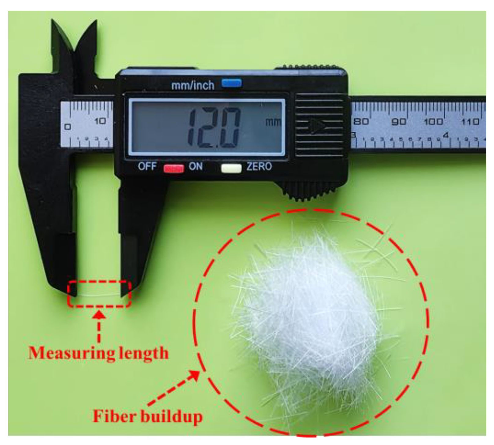
2.2. Fiber Materials

In this paper, LFR-CTB specimens were prepared using polypropylene fiber (PPF). In order to make the prepared LFR-CTB specimens with good densification, the length of PPF was chosen to be 12 mm and the radius was less than 50 µm, as shown in Figure 3. Earlier research by the same group found that the effect of fiber-reinforced CTB material was weightier when a fiber length of 12 mm was considered [66]. The density, tensile strength, elastic modulus, and elongation values of PPF were also detected as 0.91 g/cm3, 403 MPa, 3.91 GPa, and 27.6%, respectively.

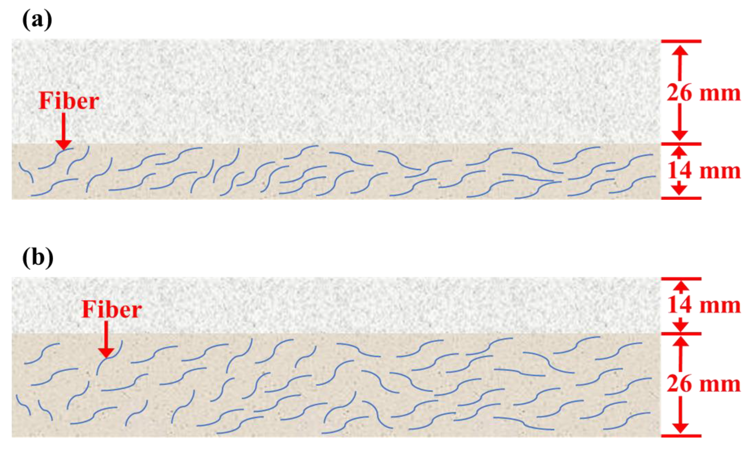
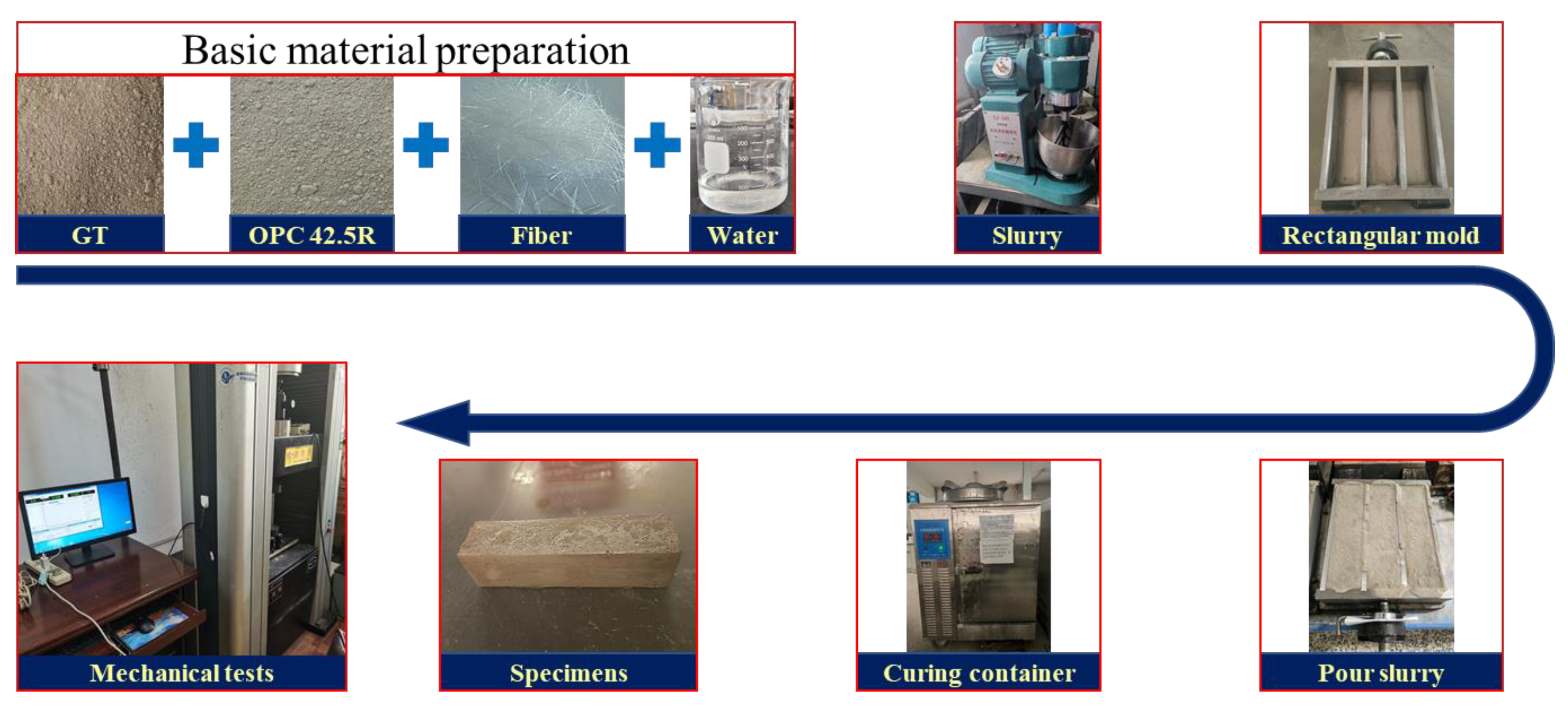
2.3. Manufacturing of Specimens

The specimens prepared for this investigation are layered specimens, and the specifications of the specific parameters of the layered specimens are revealed in Figure 4. The study’s principal purpose is to explore the fiber impact on CTB’s strength features under action of delamination. In the stratified backfill mining method, the c/t ratio is usually set between 1:4 and 1:10 [23]. Therefore, in the experiments of this paper, the c/t ratio was set to four gradients: 1:4, 1:6, 1:8, and 1:15. Particularly, 1:15 is set to inspect more specifically the flexural reinforcement of fiber-reinforced CTB in beam structures. The remaining c/t ratios are mainly set in CTB with fiber layer (CFL; called CTB specimen lower layer). A constant c/t proportion of 1:15 is mainly set in CTB without fiber layer (WFL; called CTB specimen upper layer). A total of 70 wt% and 14 days were considered as a constant solid content and curing time, respectively, for this study. The ideal quantity of fiber incorporation was found to be 0.6 wt% in an earlier study carried out by the same group members [26]. Thus, the PPF content within backfill specimen was set to 0.6 wt%. Note that in a layered specimen, the percentage of fiber mass is the percentage of the complete quantity of layer it is in. Table 1 shows the specimen preparation scheme for this investigation. Group A specimens are normal CTB specimens while group B and C specimens are LFR-CTB specimens.
The preparation procedure of backfilling was as follows: First, the weights of GTs, OPC 42.5R, PPF, and mixing water were accurately detected using an electronic scale, YHC60001. It should be mentioned here that the PPF was initially stored in clusters and the fibers should be separated and sufficiently dispersed before the subsequent mixing work. Then, the dry GTs, OPC 42.5R, and PPF products were cast in a cement net slurry blender, NJ-160, and blended for 3 min to make the PPF well dispersed within a solid material. Ordinary tap water was poured in the mixture to blend dry materials prepared at the very beginning and mixed for at least 3 min with the NJ-160 cement net slurry blender. Lastly, the manufactured LFR-CTB slurry was cast in rectangular molds sequentially. In the present study, the mold’s length/width/height values were 160/40/40 mm, respectively. The prepared LFR-CTB specimens needed to be cured in a continuous heat and moisture cure chamber: SHBY-40B cure chamber. Note that the demold time of filling was 48 h while an elapsed time of 14 days was taken as a curing age for all specimens. Figure 5 displays key preparation steps of the pre-designated LFR-CTBs.
In the filling specimen preparation step, there is an intermediate part of layered preparation. When preparing the layered specimens, it is necessary to mark the height with a pencil inside the mold wall in advance. It should be mentioned here that the pencil markings may cause the specimen to be mixed with impurities, and the specimen should be carefully sandpapered before the subsequent flexural mechanic test. In the previously mentioned step, the prepared fiber-containing CTB slurry was poured into a mold until the marked line was reached, and then it was left to stand for 10 min. When the lower layer of slurry had a certain solidification state, the pre-configured CTB slurry without fiber was poured into the mold to cover the top of the fiber-containing layer. The upper layer of the CTB specimen (CTB-SUL) did not contain fibers and the lower layer of the CTB specimen (CTB-SLL) contained fibers. The one containing fiber was termed the “containing fiber layer” (CFL) and the one without fiber was called the “without fiber layer” (WFL).

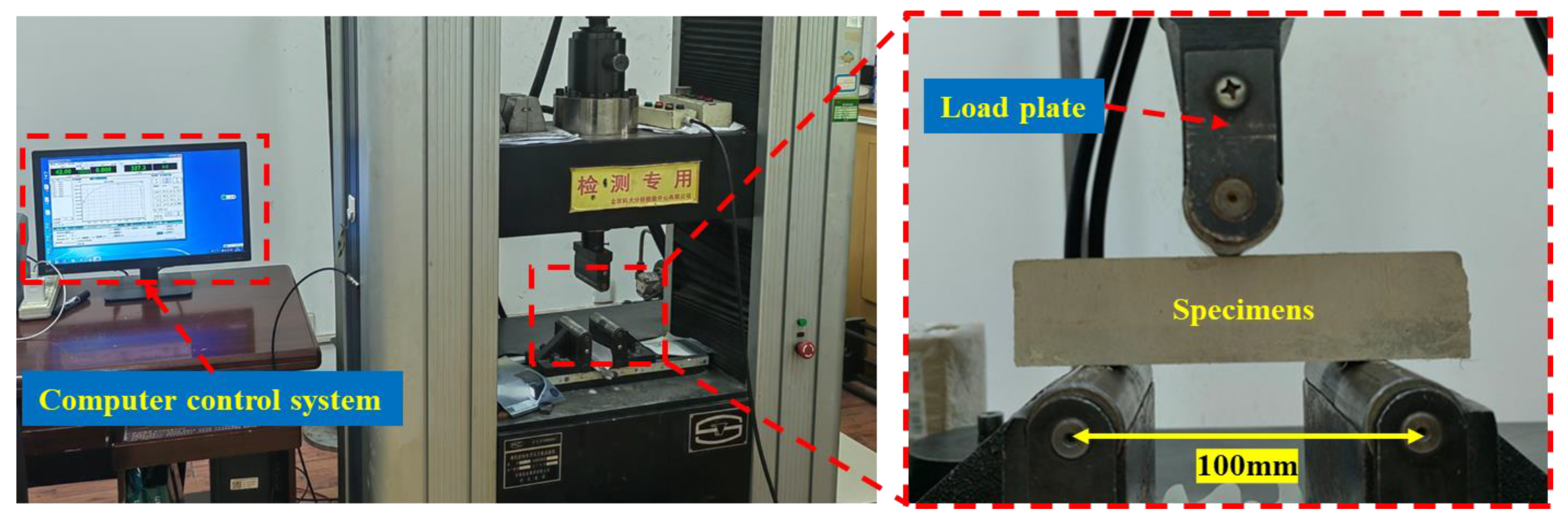
2.4. Three-Point Bending Trial

In the present study, a three-point bending flexural test structure, WDWI-100 (Figure 6), was used for testing the toughness/flexural strength of filling. Sandpaper sanding of 14-day-cured specimens was required prior to conducting the test. For unevenness of the specimen, the same sandpaper was used to smooth out the specimen. After the specimen was leveled, the specimen’s length, width, and height parameters were recorded for subsequent calculations. In the mechanic test, the three-point bending support point span was set to 100 mm, taking into account a displacement proportion of 0.5 mm per minute. After the filling specimen was loaded, the acquired deflection and load data were completely stored in the computer, and each subsequent specimen data were stored in the .Dat format.

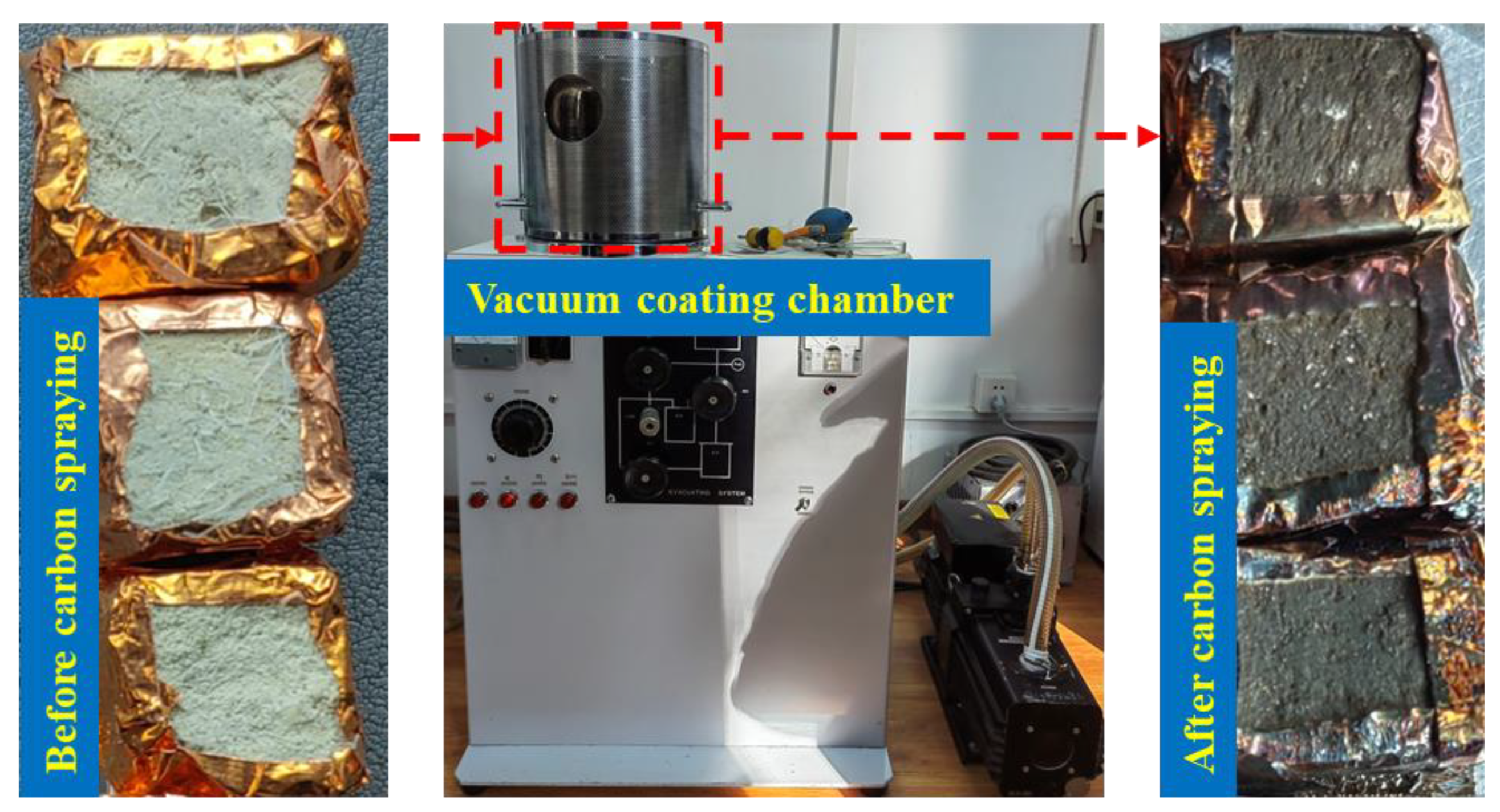
2.5. SEM Microanalysis

To explore LFR-CTB’s microstructural features, a scanning electron microscope (SEM) called Zeiss EVO-18 coupled with an energy dispersive spectrometer (EDS) was used in the present study. The test bounds were set as: a maximum quickening voltage and tenacity of 20 kV and 3 nm, respectively. A high voltage and photo resolution of 15 kV and 750–1000, respectively, were also considered during EDS test. Filling specimens needed to be suitably dried before SEM test was performed. Afterward, the specimen was coated tightly around the sample with copper paper and carbon sprayed using Hitachi vacuum evaporator Model HUS-5GB. Due to the specificity of the specimen, two carbon sprays were required to make the specimen have good electrical conductivity. Figure 7 illustrates the HUS-5GB vacuum coater. Finally, the tested specimen was placed in the vacuum hollow of the instrument and the air in the vacuum hollow was removed. Figure 8 illustrates the Zeiss EVO-18 SEM device for microstructure analyses.

3. Results and Discussion

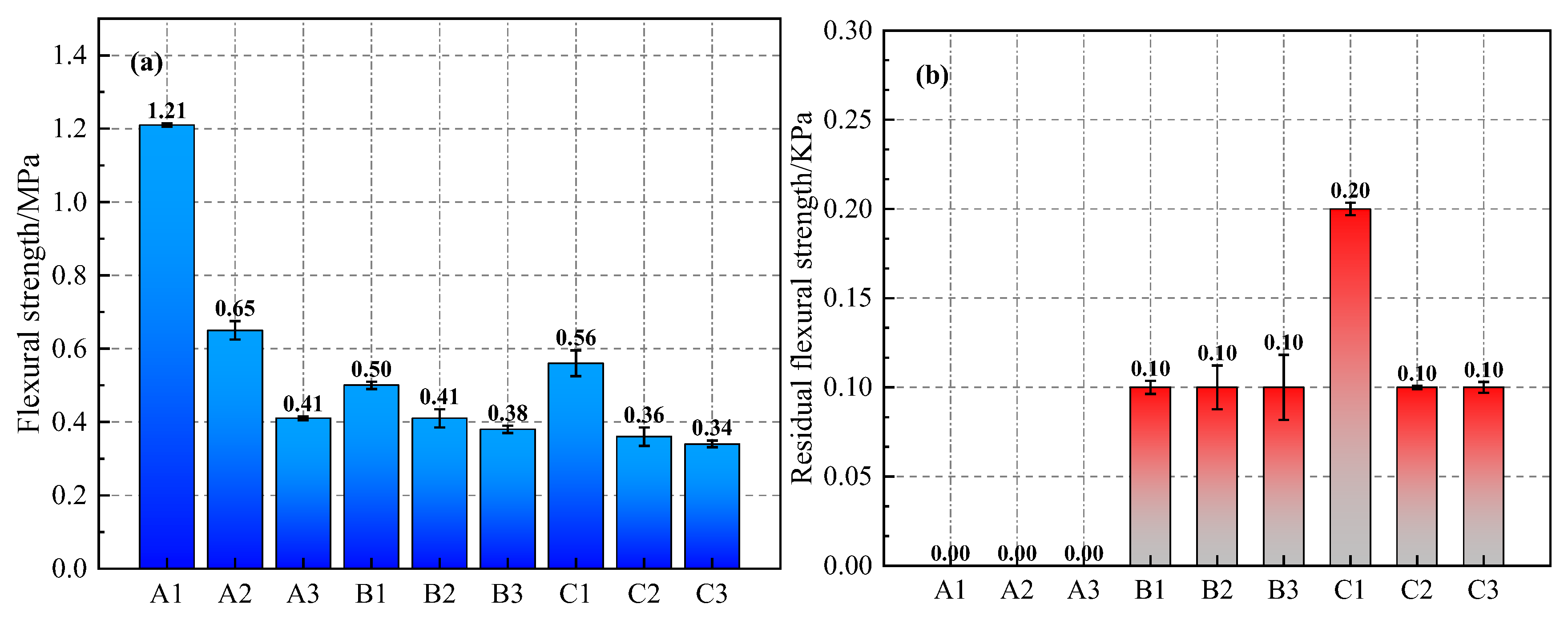
3.1. Assessment of CTB’s Flexural Strength Behavior

The backfill’s flexural strength is a good measure of the bending performance of the filling specimen. Flexural strength generally refers to the peak stress that a filling specimen can endure when it ruptures under load or reaches the specified bending moment. To assess the filling specimen’s bending strength, the following formula [67] can be used:
δ = M Z ,
where M is the bending space and Z is the specimen’s rupture modulus.
Here, both M and Z are designed as below:
M = 1 4 P L ,
Z = 1 6 b h 2 ,
where P is the highest stress value; L is the space between two-support sockets at the bottom; b is the breadth of the cross-sectional zone; and h is the elevation of the cross-sectional zone.
Figure 9 shows the bending performance limits of fills for this experiment. From Figure 9a, one can infer that specimen A1′s flexural strength (FS) is the principal, having a strength value of 1.21 MPa. FS values for all other specimens were less than A1. In group A’s specimen test, the FS of specimens A1 to A3 showed a decreasing trend. This decreasing trend represents a drop in the c/t ratio, affecting the bending features of common filling. Again, this trend is consistent with the bending performance of group B versus group C specimens. Among the specimens in group B, specimen B1 has the largest FS with a strength value of 0.5 MPa. The strength of specimen B1 was greater than specimen A3 and less than specimen A2. Note that for the group B specimens, 65% of the specimen volume was made of low-proportioned colluvial cement tailings material. Similarly, the FS values of specimen C1 was the largest in group C with a strength value of 0.56 MPa. In group C specimens, 35% of the specimen volume was made up of low-ratio colluvial cement tailings. FS values of specimen B1 and specimen C1 were similar. The FS value of specimen C1 was only 0.06 MPa greater than that of specimen B1.
From Figure 9b, one can obviously infer that after peak stress, residual flexural strength (RFS) values of specimens in group A all decreased to 0. However, the RFS values of the specimens in group B were all 0.1 kPa. In group C specimens, the RFS value of specimen C1 was 0.2 kPa, and the RFS values of specimens C2 and C3 were the same as those of group B specimens. Accordingly, the tested LFR-CTB specimens have a relatively assured load-bearing capacity after the highest stress, and adding PPF into the backfill mix could effectively enhance CTB’s bending behavior. Specimen C1 is the specimen with the best flexural strength among all LFR-CTB specimens (excluding group A specimens).

3.2. Assessment of CTB’s Toughness/Deflection Behavior

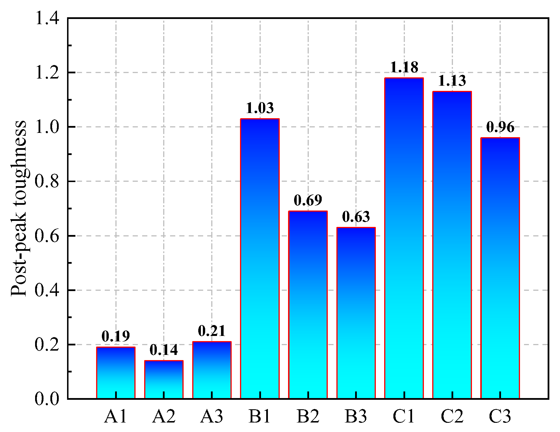
3.2.1. Toughness Analysis

In implementing underground mining methods with backfilling, CTB’s toughness determines whether workers can safely and efficiently extract the ore from underground and bring to the surface. The filling specimen’s flexural modulus (FM) is designed by using the following formula [68]:
E b = L 3 Δ F 4 b h 3 Δ f
where L is the space between two-support sockets at the bottom; b is the cross-sectional zone’s breadth; h is the cross-sectional zone’s elevation; Δ F is a rise of loading; and Δ f is deflection rise.
Figure 10 shows the average FM values for all specimens. One can infer that the average flexural modulus (AFM) values of specimens A1 to A3 within group A were 107.83 GPa, 66.06 GPa, and 48.36 GPa, respectively. Similarly, the AFM values for specimens B1 to B3 in group B and C1 to C3 in group C were 31.27 GPa, 27.76 GPa, 17.29 GPa, 21.86 GPa, 17.99 GPa, and 17.36 GPa, respectively. It can be found that AFM values of all three groups of specimens show a decreasing trend. The AFM of specimens within groups A, B, and C all diminished with the rise in the amount of tailings content. The AFM of specimen B1 was greater than that of specimen C1 in group B in comparison with specimen C1 in group C. Specimen B1 has the best AFM among all LFR-CTB specimens.
Toughness is one of the principal pointers to assess the overall strength properties of a material. To quantify the toughness of LFR-CTB specimen, peak stress was defined as a threshold point of the energy absorption of a specimen after the highest stress. As stated by the toughness assessment technique of Xue et al. [26], the durability (toughness) guide after the highest load is designated as K. A chart of the toughness assessment process is shown in Figure 11. The formula for calculating K is shown below.
K = S A B C D S A B D ,
where SABCD is the area between the curve and the coordinate system after the peak load; SABD is the area of the triangle formed by connecting the deflection coordinate point at the end of the curve with the peak load point after the peak load.
Figure 12 shows the calculated average toughness index (ATI) for all filling samples. One can infer that ATI values of the filling specimens in group A after peak load ranged from 0.14 to 0.21. Group A specimens have very small ATI values in comparison with group B and C specimens. This indicates that the specimens in group A, as a blank control group without PPF, damaged faster after peak load, and group A specimens were more fragile. The same trend can also be illustrated sideways that adding PPF could well enhance CTB’s toughness. Groups B and C specimens displayed a declining trend of ATI values with the increase in the tailings content. Among backfills in groups B and C, specimens B1 and C1 were the specimens with the largest ATI within their respective groups. ATI of specimens B1 and C1 were 1.03 and 1.18, respectively. Specimens B1 and C1 had good flexural properties in the above FS and AFM studies, and both specimens were the best specimens in their respective groups. The change in ATI was 0.15 for specimen B1 compared to specimen C1. This indicates that among all LFR-CTBs, a c/t proportion of 1:4 and a fiber layer height of 26 mm present the best toughness.

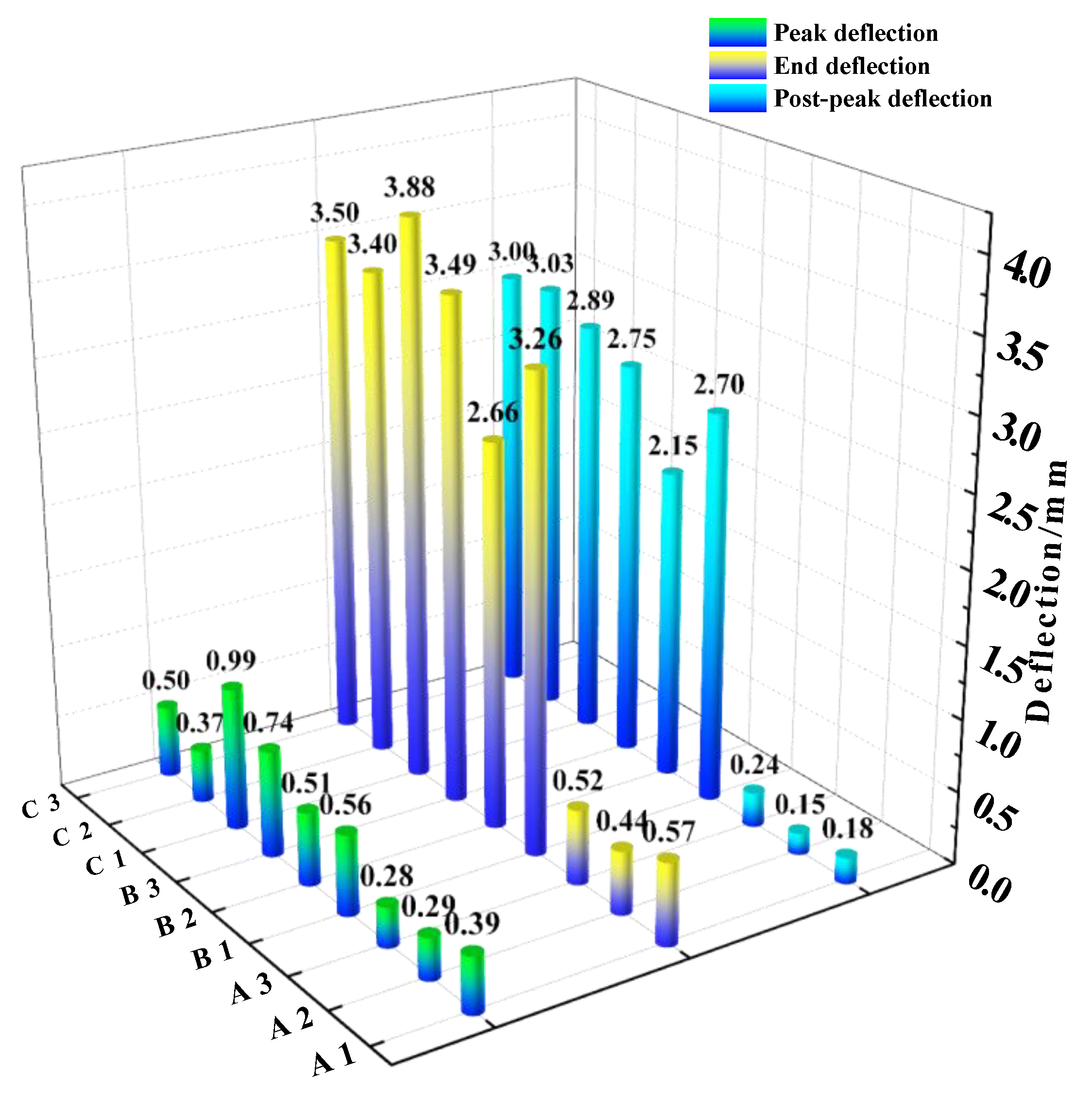
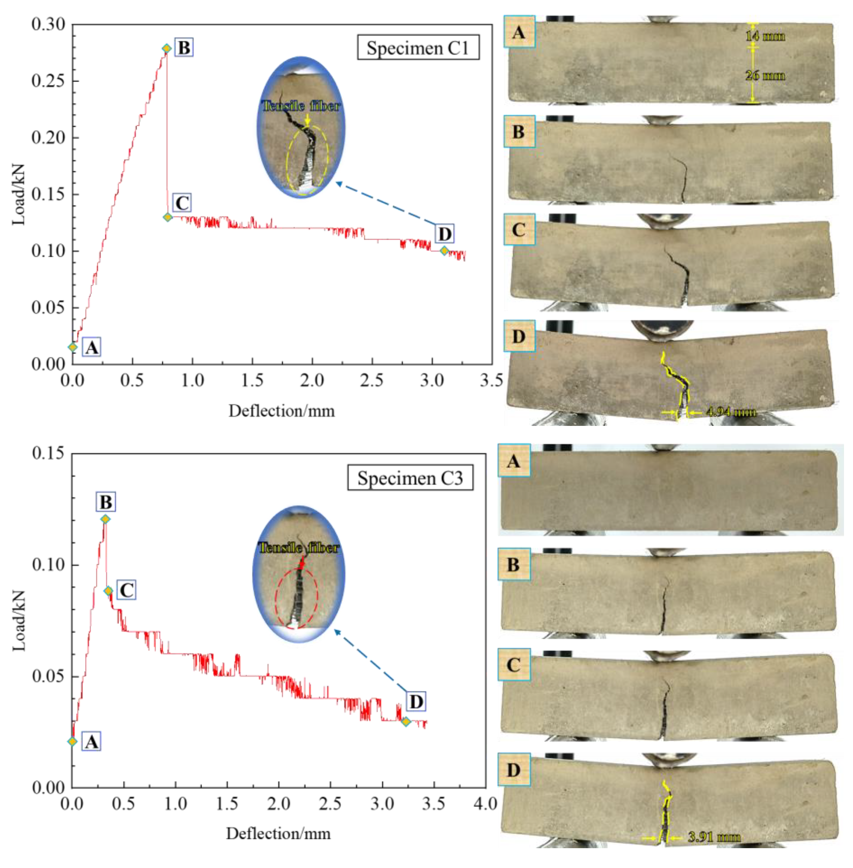
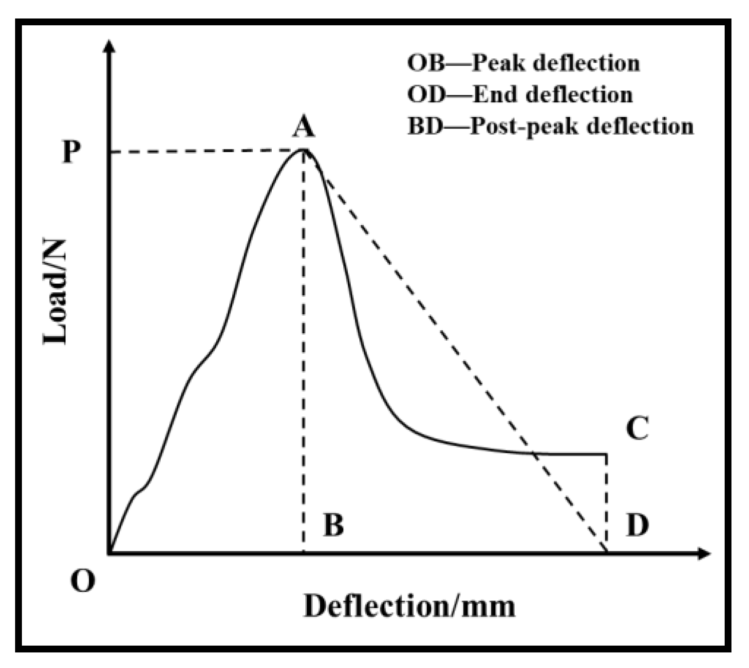
3.2.2. CTB’s Deflection Analysis

To better inspect LFR-CTB’s flexural characteristics, specimens were analyzed and studied with the deflection value as a key parameter (Figure 13). The highest deflection denotes the value of the deflection of a specimen from the load’s start to the highest strength. An ultimate deflection denotes a deflection value from the load’s start to the load’s end. Post-peak deflection denotes the deflection value of a filling specimen from the load’s start at the highest strength to the end of loading [23].
One can infer from Figure 13 that the filling sample’s highest deflection in group A did not exceed 0.4 mm. Excluding specimen C2, the peak deflections of all other specimens in groups B and C were not less than 0.5 mm and did not exceed 1 mm. This indicates that incorporating PPF has an impact on the deflection growth of the specimen before the peak load. What can also be found is that the increment of deflection value is smaller for groups B and C’s specimens compared to group A’s specimens, and the PPF has less of an effect on the early deflection of CTB.
The deflection of all specimens continues to increase as the load is loaded from peak strength to the end. Groups B and C’s specimens showed larger increments of deflection compared to group A’s specimens. At the end of the loading of group A’s specimens, none of the end deflections exceeded 0.6 mm, and the growth was low. The size of the end deflection of group B’s specimens was regular: B3 > B1 > B2. The size of the end deflection of group C’s specimens was regular: C1 > C3 > C2. What can be found is that the end deflection of all specimens in group C was larger than the end deflection of specimens in group B. By comparing each group’s post-peak deflection, it can be found that the post-peak deflection of the specimens in group A was lower, with deflection values ranging from 0.15 to 0.24 mm. The post-peak deflection was higher for both groups B and C’s specimens, with deflection values ranging from 2.15 to 3.03 mm. In group B, specimen B3 had the largest post-peak deflection with a deflection value of 2.75 mm. In group C, specimen C1 had the smallest post-peak deflection with a deflection value of 2.89 mm. The difference between the post-peak deflection of specimens B3 and C1 was only 0.14 mm. However, the end deflections of specimens C1 and B3 were the maximum values within their respective groups of groups B and C, with deflection values of 3.88 mm and 3.49 mm, respectively. Variance between the end deflection of specimens C1 and B3 was 0.39 mm. Similar to ATI analysis, specimen C1 was the optimal specimen in the deflection analysis. This indicates that the deflection features of specimens with a c/t proportion of 1:4 and a fiber layer height of 26 mm are optimal.

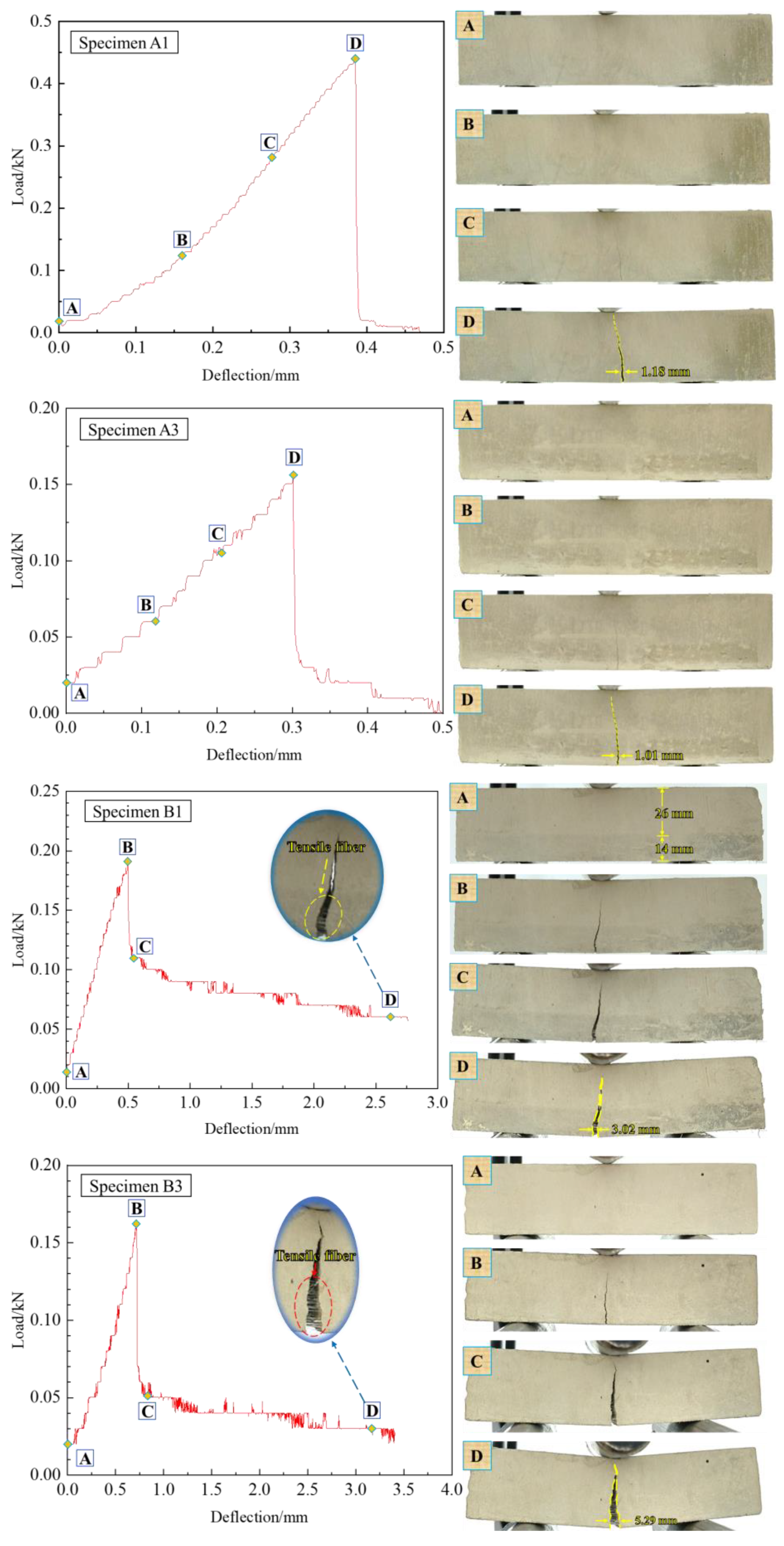
3.3. Analysis of LFR-CTB’s Failure Mode

Figure 14 indicates the failure mode of the specimen under three-point bending test conditions. According to the changing state of the load–deflection bend of tested fills, four themes, A, B, C, and D, were divided to analyze specimens’ damage process. What can be noticed is that the width of the specimen damage’s main crack dimension is marked in Figure 14 using the measurement function in the open-source software ImageJ. The test outcomes displayed that the specimen’s damage mode was tensile damage. As the damage pattern of specimens A1 and A3 in Figure 14 were found, the general CTB without added fibers broke down rapidly after the peak load. It should be noted here that the load–deflection curves of A1 and A3 specimens still have partial displacement after peak load, but CTB load strength tends to 0 at this time, and CTB itself no longer has sufficient load-bearing performance. The main crack expansion directions of specimens A1 and A3 were the same and not similar to the stress route, and the highest widths of the leading cracks were 1.18 mm and 1.01 mm, respectively. Nonetheless, load–deflection curves of samples B1 and B3 of group B and samples C1 and C3 of group C were different from those of group A. LFR-CTB specimens could not break immediately after peak stress and exhibited significant ductility. This is since fibers have a substantial inhibitory impact on the expansion of cracks. The results were basically the same as those of the same group members [23]. The difference is that the extreme damage primary crack size width of the specimens in this study was lower. The maximum primary cracks at point D were 3.02 mm, 5.29 mm, 4.94 mm, and 3.91 mm for specimens B1, B3, C1, and C3, respectively. Comparing the damage pattern of specimens in group A with those in groups B and C, it can be found that CTB without added fibers has a faster main crack expansion and shorter damage failure time during loading.
The upper layer of LFR-CTB did not contain fibers and the main crack of the upper layer expanded fast, while the lower layer of LFR-CTB contained fibers and the main crack of the lower layer expanded slowly. As shown in Figure 15, it can be observed from the partial magnification of the specimen damage that some fibers located in the center of the main crack of the specimen produced a bridging effect, which inhibited the crack expansion and prevented the damage to the specimen. Moreover, LFR-CTB main crack extension dimensions were all larger than those of normal CTBs. It can be shown that LFR-CTB had lost its supporting effect in the upper layer of CTB without fibers at the late stage of loading, and the supporting performance of the later layer mainly depended on the lower layer of CTB containing fibers. CTB-covering fibers in the lower layer had a supporting effect on CTB without fibers in the upper layer, preventing the overall fracture of the specimen. Note that the load–deflection damage form and crack expansion pattern of LFR-CTB specimens were quite different. The fiber-doped LFR-CTBs possessed a load-bearing capacity after damage, and the fiber incorporation could enhance CTB’s flexural features.

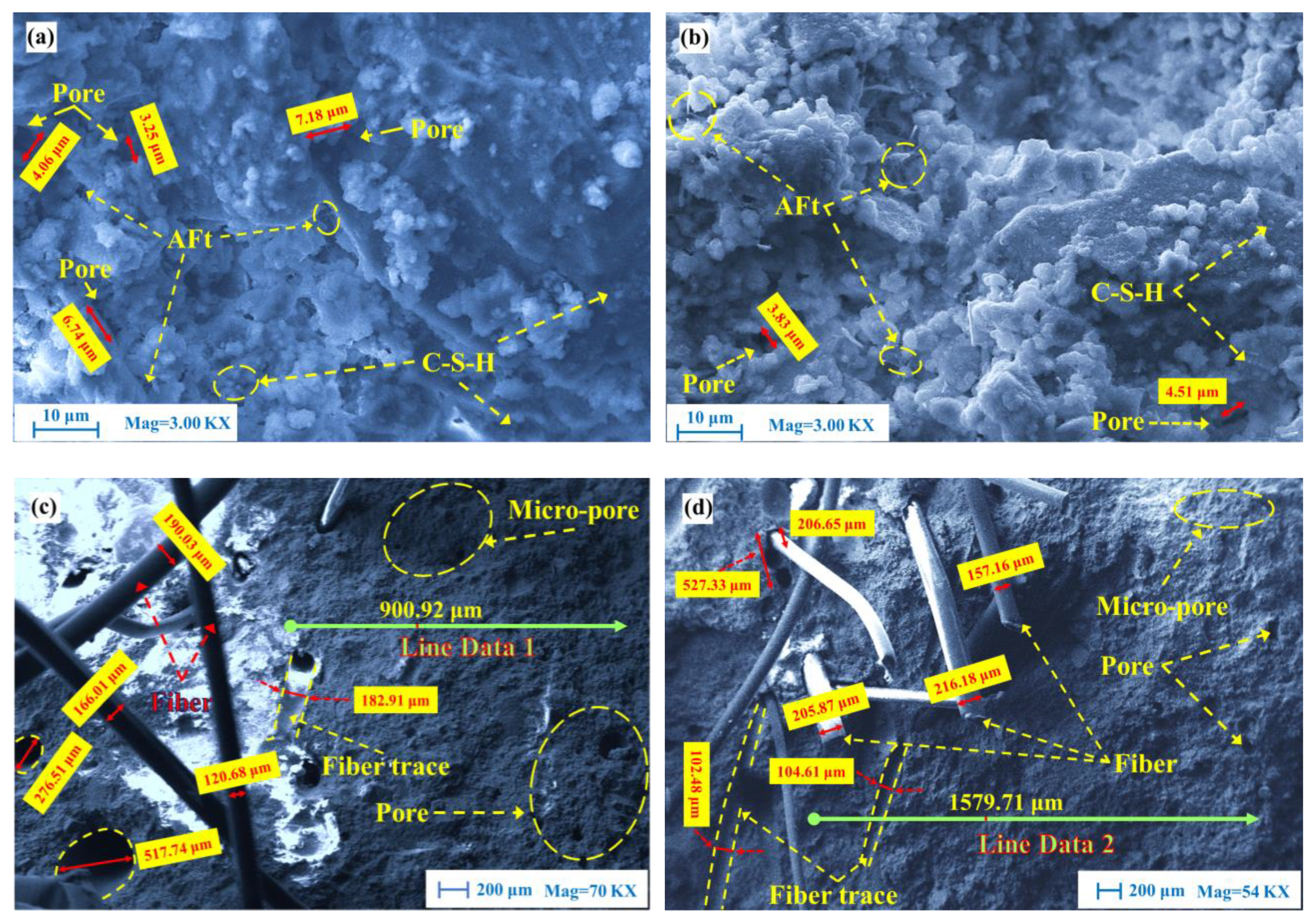
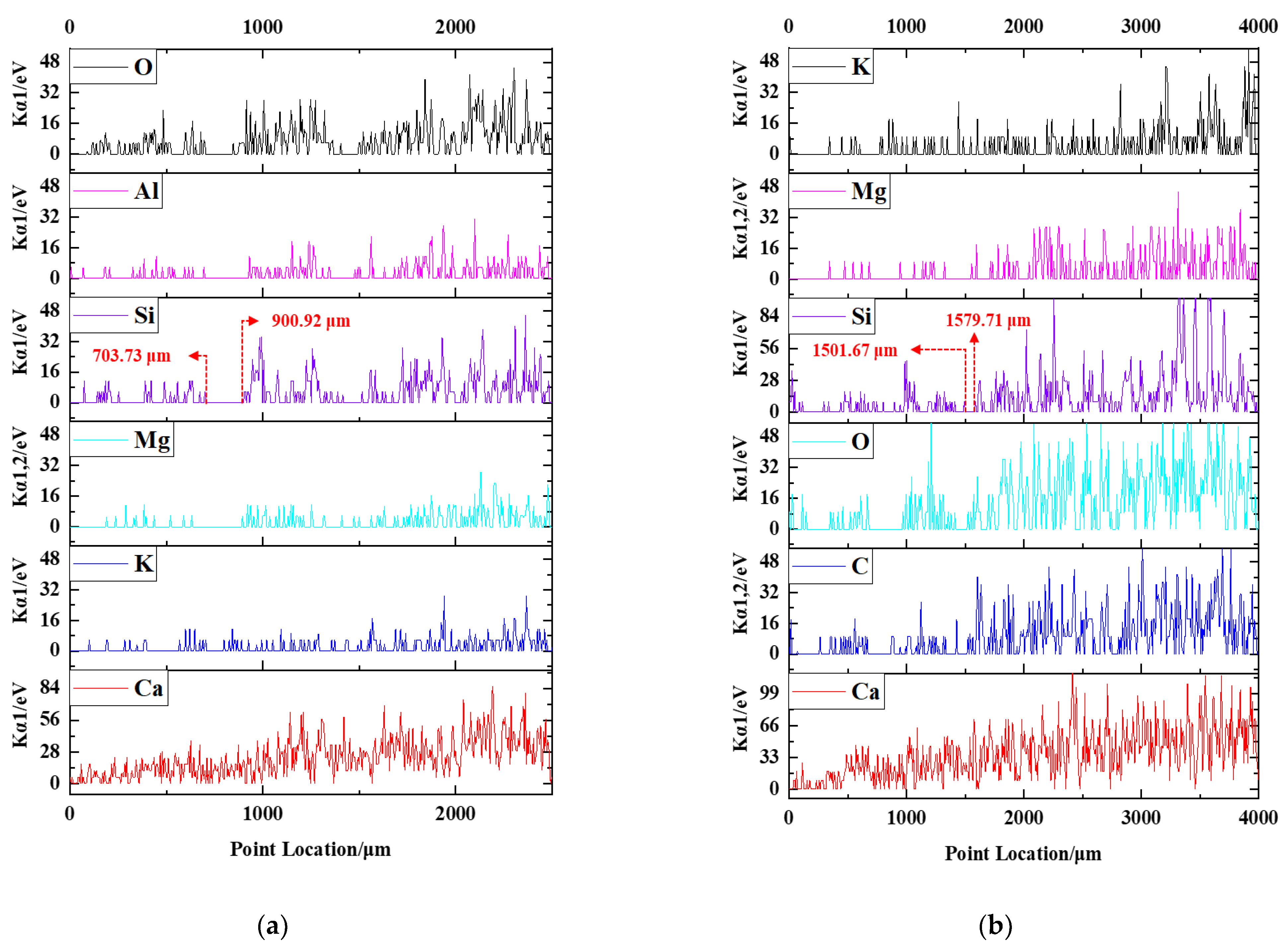
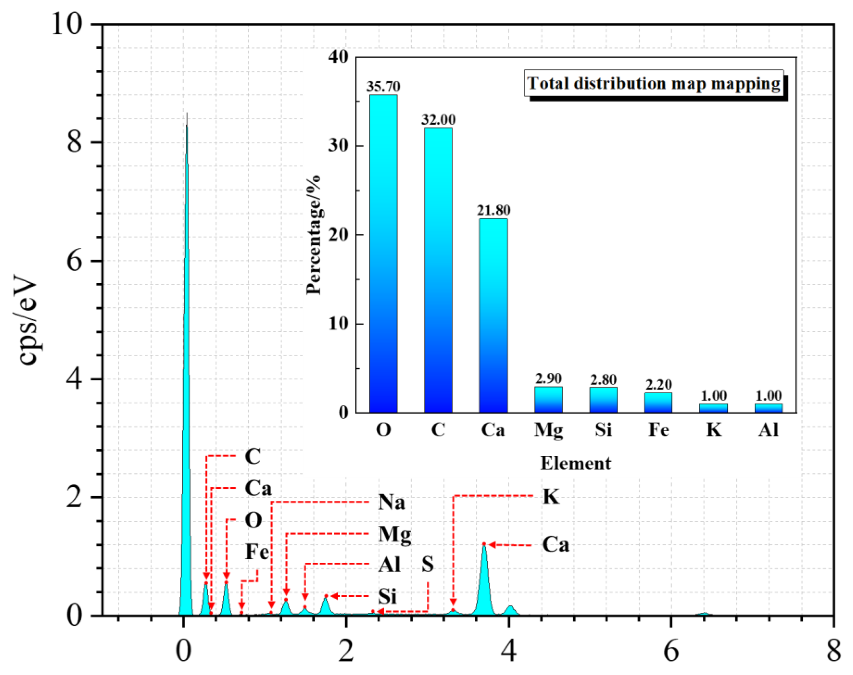
3.4. CTB’s Microanalysis

Figure 16 displays some SEM micrographs of filling specimens. The specimens’ surfaces are mainly distributed with fibers, pores, and cracks. Figure 16a,b show the microstructures of specimens A2 and B2. One can visibly perceive that a large amount of ettringite (AFt, where A represents Al, F represents Fe, and t represents trisulfide) and CSH gels accumulated on the specimens’ surfaces, magnified 3000 times.
According to previous studies, it is known that CTB contains numerous hydration materials, which are closely related to CTB’s high flexural strength [41]. One can also witness from Figure 16c,d that fibers are interspersed inside CTB and the fiber surface is smoother with fine hydration products linked to the fiber surface. The fibers bend and deform as they pull away from the stretch between CTB cracks. The diameters of the exposed fibers were measured using the measurement function of ImageJ software, and the diameters of fibers after loading ranged from 120.68 μm to 216.18 μm; the diameters of fibers were reduced by tension. Some traces of varying particles were likewise established. Traces’ thickness values were 182.91 μm, 102.48 μm, and 104.61 μm, respectively. Fiber diameter has a major variance from the trace width. The motive for this change is that fibers stretch and become finer during loading, and fibers share some of the load on CTB, improving the fill’s toughness. From Figure 16d, one can detect that the exposed joint width of fibers is 206.65 μm at the joint of fibers within CTB. The total length of pores linked to the exposed joint is 527.33 μm. This result can show that the position and angle of fibers have great freedom due to the uniform distribution of fibers in CTB. While the filling specimen is loaded, the fiber located in the loaded area is stretched by force, and the direction of stretching is mainly in the vertical loading direction. In the loading direction, fibers gradually squeeze CTB, which makes CTB on the upper surface of fibers gather densely and hinders the upward movement of fibers, and inhibits the crack expansion.
Groups B and C’s specimens are layered specimens. Under SEM magnification, there is essentially no difference at the demarcation interface between the lower layer containing fibers and the upper layer not containing fibers. Thus, a straight line is designated on specimens B2 and C2 for elemental acquisition scanning and qualitative analysis of specimen demarcation interface. Figure 17a,b show the line data extracted from the surfaces of specimens B2 and C2. The chemical composition of tailings has been determined before this section, and SiO2 is found to be the most abundant chemical element. Specimens B2 and C2 have a higher content of upper tailings than lower ones. From the line data of Si in Figure 17a, it can be seen that the value of Kα1 energy for Si between 703.73 μm and 900.92 μm is 0.04 eV. The mean value of Kα1 energy behind the 900.92 μm position is higher than that in front of 900.92 μm, and 900.92 μm is judged as the demarcation interface. The same method is used in Figure 17b to obtain 1579.71 μm as the dividing interface. It can be found that the cementation between superior and minor layers is more complete and the specimen is more integral. The superior and minor layers are distinguished by a line data collection of lines in Figure 16c,d. The upper CTB layer has more pores as well as micro-pores, and the lower layer pores are mainly distributed around fibers. The overall cementation of LFR-CTBs was excellent, and adding fiber delamination did not change CTB’s structural morphology. The presence of the interlayer interface does not affect the bending performance of LFR-CTB specimens.
The EDS energy spectrum data and the elemental mapping distribution of normal CTB are given in Figure 18. It can be found that CTB’s microstructure surface is dominated by O, C, Ca, Mg, Si, Fe, K, and Al. Leading elements are O, Ca, Mg, and Si (the high C content is due to the carbon spraying treatment of specimens before SEM observations).

4. Conclusions

To further explore the flexural performance of LFR-CTB specimens, numerous experiments such as three-point bending and microanalysis were conducted on LFR-CTB specimens in this study. The key findings are given below:
  • An FS value of a normal CTB specimen without fiber delamination and with a c/t proportion of 1:4 was the largest at a curing time of 14 days. By the decline in a c/t ratio, FS values of CTBs without fiber delamination showed the same decreasing trend as those of LFR-CTBs. However, RFS values of all LFR-CTBs were greater than those of CTBs without fiber delamination, indicating that adding fiber delamination can effectively enhance CTB’s flexural features.
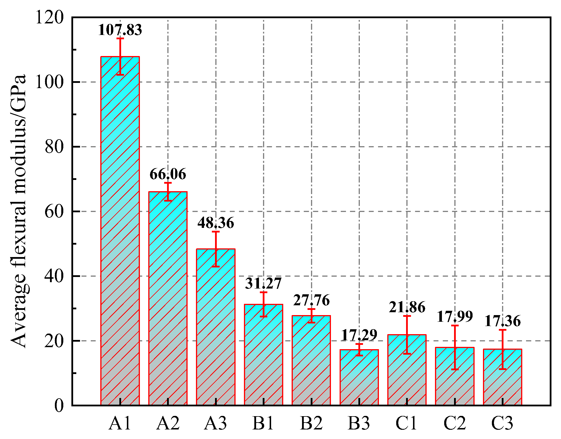
  • The largest AFM values were obtained for the CTB specimens without fiber delamination. When the c/t ratio reduced, AFM values of CTBs without fiber delamination showed the same decreasing trend as those of the LFR-CTB specimens.
  • LFR-CTBs provided larger ATI values than CTB without fiber delamination, showing that adding fiber delamination facilitates the growth of CTB’s post-peak toughness. LFR-CTBs with a higher fiber delamination dimensional height have excellent flexural properties.
  • The damage modes of CTBs and LFR-CTBs are mainly tensile damage along the loading route, and principal crack is chiefly in line with loading route with a small angle.
  • Adding fiber delamination affected CTB’s strength features, resulting in enhanced filling ductility. The comparison of deflection values shows that the post-peak ductility of LFR-CTBs with a higher dimensional height of fiber delamination is larger than that of fills with a lower dimensional height.
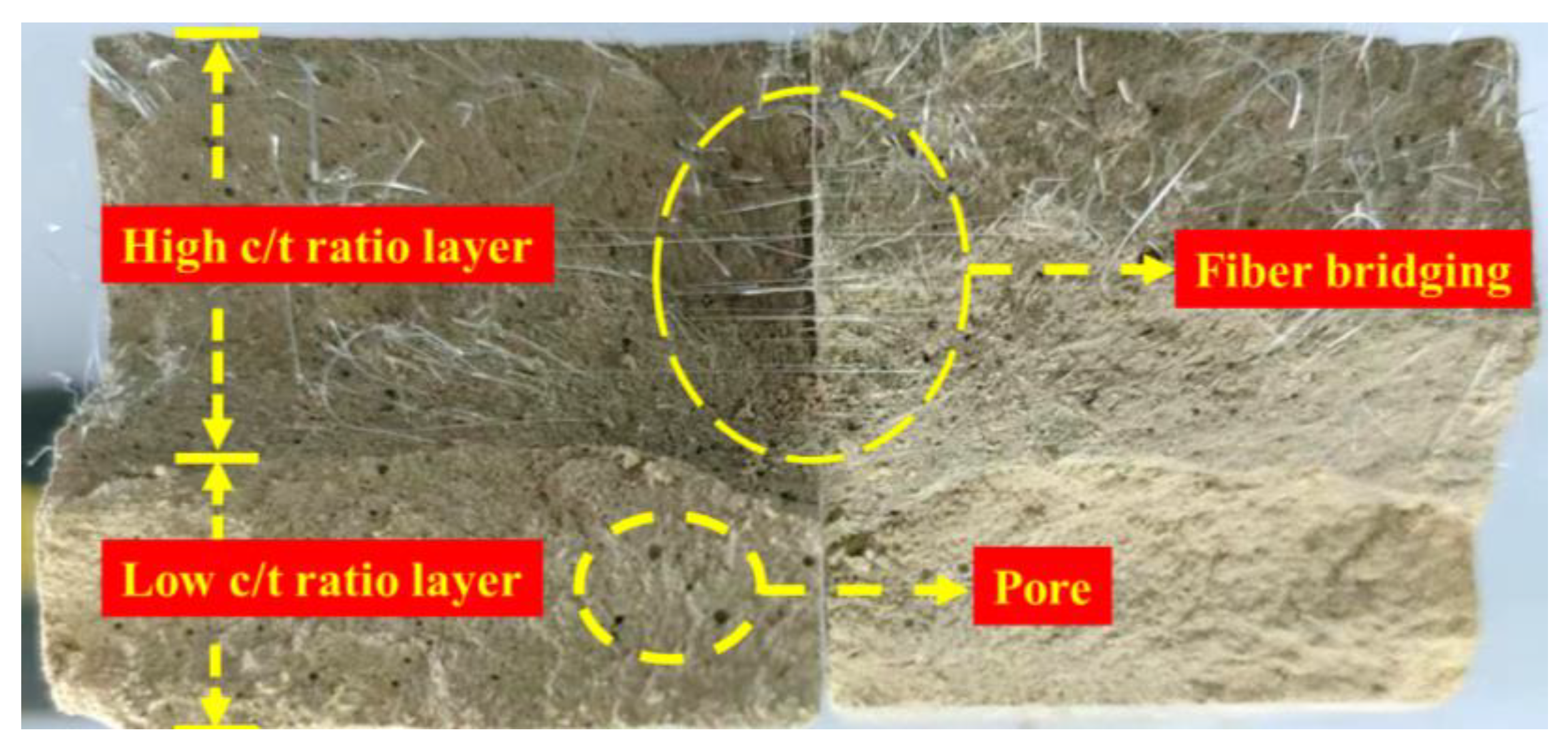
  • The boundaries of the layered interface of LFR-CTB were delineated by SEM microstructure analysis. Variance between the delamination’s upper and lower interfaces is small according to the microscopic image observation.
  • The overall bonding of LFR-CTBs is excellent, and the presence of interlayer interfaces does not affect the overall bending performance of LFR-CTB specimens.
For CTB, an excellent flexural performance and low cost are key indicators for mine fill applications. In order to prepare CTB specimens with excellent flexural properties and low cost, the layered preparation proposed in this study can diminish the backfill-related overall costs and enhance tailings’ utilization, leading to sustainable mining and filling operations. In the coming weeks, the same research team will focus on integrating indoor experiments with practical engineering applications. Furthermore, layered backfill will be a more important research direction in underground mine fill work. In the future research work, the simulation reconstruction and numerical computation analysis of layered filling is also a more important research direction. Moreover, with the development of computer science and technology, the combination of computer and filling body application analysis will also be an important research direction.

Author Contributions

Conceptualization, S.C.; methodology, Z.Z.; writing—original draft preparation, Z.Z.; writing—review and editing and supervision, E.Y. and S.C.; funding acquisition, S.C. All authors have read and agreed to the published version of the manuscript.

Funding

We want to honorably recognize substantial funds being granted by the National Key Research and Development Program of China (grant number: 2022YFC2905004).

Data Availability Statement

No applicable.

Conflicts of Interest

The authors declare no conflict of interest.

Nomenclature

GTsGold tailings
PPFPolypropylene fiber
CTBCemented tailings backfill
WFLWithout fiber layer
CFLContains fiber layer
LFR-CTBLayered-fiber-reinforced CTB
FRCTBFiber-reinforced cemented tailings backfill
CTB-SLLCTB specimen lower layer
CTB-SULCTB specimen upper layer
FMFlexural modulus
AFtEttringite
AFMAverage flexural modulus
SEMScanning electron microscope
FSFlexural strength
RFSResidual flexural strength
ATIAverage toughness index
c/tCement/tailings
OPCOrdinary Portland cement
PSDParticle size distribution
USTBUniversity of Science and Technology Beijing
EDSEnergy dispersive spectrometer
C-S-HCalcium silicate hydrate

References

  1. Sotoudeh, F.; Nehring, M.; Kizil, M.; Knights, P.; Mousavi, A. A novel cut-off grade method for increasing the sustainability of underground metalliferous mining operations. Miner. Eng. 2021, 172, 107168. [Google Scholar] [CrossRef]
  2. Khandani, F.S.; Atapour, H.; Rad, M.Y.; Khosh, B. An experimental study on the mechanical properties of underground mining backfill materials obtained from recycling of construction and demolition waste. Case Stud. Constr. Mater. 2023, 18, e02046. [Google Scholar] [CrossRef]
  3. Chung, J.; Asad, M.W.A.; Topal, E. Timing of transition from open-pit to underground mining: A simultaneous optimisation model for open-pit and underground mine production schedules. Resour. Policy 2022, 77, 102632. [Google Scholar] [CrossRef]
  4. Xue, G.L.; Yilmaz, E.; Wang, Y. Progress and prospects of mining with backfill in metal mines in China. Int. J. Miner. Metall. Mater. 2023, 30, 1455–1473. [Google Scholar] [CrossRef]
  5. Esmailzadeh, S.; Bakhtavar, E.; Mokhtarian-Asl, M.; Sadiq, R.; Hewage, K. Mathematical modelling of waste rock management through incorporating open-pit waste rocks in underground stope filling: An environmental approach. Resour. Policy 2023, 85, 103885. [Google Scholar] [CrossRef]
  6. Kalisz, S.; Kibort, K.; Mioduska, J.; Lieder, M.; Małachowska, A. Waste management in the mining industry of metals ores, coal, oil and natural gas-A review. J. Environ. Manag. 2022, 304, 114239. [Google Scholar] [CrossRef]
  7. Yilmaz, E.; Koohestani, B.; Cao, S. Chapter 13-Recent practices in mine tailings’ recycling and reuse. In Managing Mining and Minerals Processing Wastes; Qi, C.C., Benson, C.H., Eds.; Elsevier: Amsterdam, The Netherlands, 2023; pp. 271–304. [Google Scholar] [CrossRef]
  8. Liu, Q.; Liu, D.; Liu, X.; Gao, F.; Li, S. Research and application of surface paste disposal for clay-sized tailings in tropical rainy climate. Int. J. Miner. Process. 2016, 157, 227–235. [Google Scholar] [CrossRef]
  9. Zhou, Y.; Fall, M. Mechanical and microstructural properties of cemented paste backfill with chloride-free antifreeze additives in subzero environments. J. Mater. Civ. Eng. 2023, 35, 04023148. [Google Scholar] [CrossRef]
  10. Carnogursky, E.A.; Fall, M.; Haruna, S. Rheology and setting time of saline cemented paste backfill. Miner. Eng. 2023, 202, 108258. [Google Scholar] [CrossRef]
  11. Hu, Y.; Li, K.; Zhang, B.; Han, B. Development of cemented paste backfill with superfine tailings: Fluidity, mechanical properties, and microstructure characteristics. Materials 2023, 16, 1951. [Google Scholar] [CrossRef]
  12. Yilmaz, E.; Belem, T.; Benzaaoua, M. Study of physico-chemical and mechanical characteristics of consolidated and unconsolidated cemented paste backfills. Gospod. Surowcami Miner.-Miner. Resour. Manag. 2013, 29, 81–100. [Google Scholar] [CrossRef]
  13. Chen, Q.S.; Zhou, H.; Wang, Y.; Li, X.; Zhang, Q.; Feng, Y.; Qi, C.C. Resistance loss in cemented paste backfill pipelines: Effect of inlet velocity, particle mass concentration, and particle size. Materials 2022, 15, 3339. [Google Scholar] [CrossRef] [PubMed]
  14. Cao, S.; Xue, G.L.; Yilmaz, E.; Yin, Z. Assessment of rheological and sedimentation characteristics of fresh cemented tailings backfill slurry. Int. J. Min. Reclam. Environ. 2021, 35, 319–335. [Google Scholar] [CrossRef]
  15. Mafra, C.; Bouzahzah, H.; Stamenov, L.; Gaydardzhiev, S. An integrated management strategy for acid mine drainage control of sulfidic tailings. Miner. Eng. 2022, 185, 107709. [Google Scholar] [CrossRef]
  16. Yan, B.X.; Jia, H.; Yang, Z.; Yilmaz, E.; Liu, H. Goaf instability in an open pit iron mine triggered by dynamics disturbance: A large-scale similar simulation. Int. J. Min. Reclam. Environ. 2023, 37, 606–629. [Google Scholar] [CrossRef]
  17. Krishna, R.S.; Mishra, J.; Meher, S.; Das, S.K.; Mustakim, S.M.; Singh, S.K. Industrial solid waste management through sustainable green technology: Case study insights from steel and mining industry in Keonjhar, India. Mater. Today Proc. 2020, 33, 5243–5249. [Google Scholar] [CrossRef]
  18. Li, J.J.; Cao, S.; Yilmaz, E. Characterization of macro mechanical properties and microstructures of cement-based composites prepared from fly ash, gypsum and steel slag. Minerals 2022, 12, 6. [Google Scholar] [CrossRef]
  19. Benzaazoua, M.; Belem, T.; Yilmaz, E. Novel lab tool for paste backfill. Can. Min. J. 2006, 127, 31–32. [Google Scholar]
  20. Weilv, W.; Xu, W.; Jianpin, Z. Effect of inclined interface angle on shear strength and deformation response of cemented paste backfill-rock under triaxial compression. Constr. Build. Mater. 2021, 279, 122478. [Google Scholar] [CrossRef]
  21. Xiu, Z.; Wang, S.; Ji, Y.; Wang, F.; Ren, F.; Wang, P. An analytical model for the triaxial compressive stress-strain relationships of cemented pasted backfill (CPB) with different curing time. Constr. Build. Mater. 2021, 313, 125554. [Google Scholar] [CrossRef]
  22. Qi, C.C.; Chen, Q.S.; Fourie, A.; Tang, X.; Zhang, Q.; Dong, X.; Feng, Y. Constitutive modelling of cemented paste backfill: A data-mining approach. Constr. Build. Mater. 2019, 197, 262–270. [Google Scholar] [CrossRef]
  23. Huang, Z.Q.; Cao, S.; Yilmaz, E. Investigation on the flexural strength, failure pattern and microstructural characteristics of combined fibers reinforced cemented tailings backfill. Constr. Build. Mater. 2021, 300, 124005. [Google Scholar] [CrossRef]
  24. Li, Z.W.; Yang, X.L. Required strength of geosynthetics for reinforced 3D slopes in cohesive backfills with tensile strength cut-off. Geotext. Geomembr. 2019, 47, 729–739. [Google Scholar] [CrossRef]
  25. Xia, K.; Chen, C.; Liu, X.; Liu, X.; Yuan, J.; Dang, S. Assessing the stability of high-level pillars in deeply-buried metal mines stabilized using cemented backfill. Int. J. Rock Mech. Min. Sci. 2023, 170, 105489. [Google Scholar] [CrossRef]
  26. Xue, G.L.; Yilmaz, E.; Feng, G.R.; Cao, S. Bending behavior and failure mode of cemented tailings backfill composites incorporating different fibers for sustainable construction. Constr. Build. Mater. 2021, 289, 123163. [Google Scholar] [CrossRef]
  27. Aldhafeeri, Z.; Fall, M. Coupled effect of sulphate and temperature on the reactivity of cemented tailings backfill. Int. J. Min. Reclam. Environ. 2021, 35, 80–94. [Google Scholar] [CrossRef]
  28. Li, J.J.; Cao, S.; Yilmaz, E.; Liu, Y.P. Compressive fatigue behavior and failure evolution of additive fiber-reinforced cemented tailings composites. Int. J. Miner. Metall. Mater. 2022, 29, 345–355. [Google Scholar] [CrossRef]
  29. Qi, C.C.; Ly, H.-B.; Le, L.M.; Yang, X.; Guo, L.; Pham, B.T. Improved strength prediction of cemented paste backfill using a novel model based on adaptive neuro fuzzy inference system and artificial bee colony. Constr. Build. Mater. 2021, 284, 122857. [Google Scholar] [CrossRef]
  30. Zhang, S.Y.; Ren, F.Y.; Guo, Z.B.; Qiu, J.P.; Ding, H.X. Strength and deformation behavior of cemented foam backfill in the sub-zero environment. J. Mater. Res. Technol. 2020, 9, 9219–9231. [Google Scholar] [CrossRef]
  31. Fang, K.; Ren, L.; Jiang, H.Q. Development of Mode I and Mode II fracture toughness of cemented paste backfill: Experimental results of the effect of mix proportion, temperature and chemistry of the pore water. Eng. Fract. Mech. 2021, 258, 108096. [Google Scholar] [CrossRef]
  32. Cui, L.; McAdie, A. Experimental study on evolutive fracture behavior and properties of sulfate-rich fiber-reinforced cemented paste backfill under pure mode-I, mode-II, and mode-III loadings. Int. J. Rock Mech. Min. Sci. 2023, 169, 105434. [Google Scholar] [CrossRef]
  33. Liu, W.; Yu, H.; Wang, S.; Wei, M.; Wang, X.; Song, X. Evolution mechanism of mechanical properties of cemented tailings backfill with partial replacement of cement by rice straw ash at different binder content. Powder Technol. 2023, 419, 118344. [Google Scholar] [CrossRef]
  34. Yang, B.; Wang, X.; Gu, C.; Yang, F.; Liu, H.; Jin, J.; Zhou, Y. The failure mechanical properties of cemented paste backfill with recycled rubber. Materials 2023, 16, 3302. [Google Scholar] [CrossRef]
  35. Guner, N.U.; Yilmaz, E.; Sari, M.; Kasap, T. Cementitious backfill with partial replacement of Cu-rich mine tailings by sand: Rheological, mechanical and microstructural properties. Minerals 2023, 13, 437. [Google Scholar] [CrossRef]
  36. Lu, H.; Sun, Q. Preparation and strength formation mechanism of calcined oyster shell, red mud, slag, and iron tailing composite cemented paste backfill. Materials 2022, 15, 2199. [Google Scholar] [CrossRef]
  37. Zhang, H.; Cao, S.; Yilmaz, E. Carbon nanotube reinforced cementitious tailings composites: Links to mechanical and microstructural characteristics. Constr. Build. Mater. 2023, 365, 130123. [Google Scholar] [CrossRef]
  38. Li, J.J.; Cao, S.; Song, W.D. Distribution development of pore/crack expansion and particle structure of cemented solid-waste composites based on CT and 3D reconstruction techniques. Constr. Build. Mater. 2023, 376, 130966. [Google Scholar] [CrossRef]
  39. Yi, X.W.; Ma, G.W.; Fourie, A. Centrifuge model studies on the stability of fiber reinforced cemented paste backfill stopes. Geotext. Geomembr. 2018, 46, 396–401. [Google Scholar] [CrossRef]
  40. Wang, Y.; Yu, Z.; Wang, H. Experimental investigation on some performance of rubber fiber modified cemented paste backfill. Constr. Build. Mater. 2021, 271, 121586. [Google Scholar] [CrossRef]
  41. Qin, S.W.; Cao, S.; Yilmaz, E.; Li, J.J. Influence of types and shapes of 3D printed polymeric lattice on ductility performance of cementitious backfill composites. Constr. Build. Mater. 2021, 307, 124973. [Google Scholar] [CrossRef]
  42. Xu, W.; Li, Q.; Zhang, Y. Influence of temperature on compressive strength, microstructure properties and failure pattern of fiber-reinforced cemented tailings backfill. Constr. Build. Mater. 2019, 222, 776–785. [Google Scholar] [CrossRef]
  43. Wang, A.A.; Cao, S.; Yilmaz, E. Effect of height to diameter ratio on dynamic characteristics of cemented tailings backfills with fiber reinforcement through impact loading. Constr. Build. Mater. 2022, 322, 126448. [Google Scholar] [CrossRef]
  44. Bhutta, A.; Borges, P.H.; Zanotti, C.; Farooq, M.; Banthia, N. Flexural behavior of geopolymer composites reinforced with steel and polypropylene macro fibers. Cem. Concr. Compos. 2017, 80, 31–40. [Google Scholar] [CrossRef]
  45. Zhang, H.; Cao, S.; Yilmaz, E. Influence of 3D-printed polymer structures on dynamic splitting and crack propagation behavior of cementitious tailings backfill. Constr. Build. Mater. 2022, 343, 128137. [Google Scholar] [CrossRef]
  46. Yang, J.; Zhao, K.; Yu, X.; Yan, Y.; He, Z.; Lai, Y.; Zhou, Y. Crack classification of fiber-reinforced backfill based on Gaussian mixed moving average filtering method. Cem. Concr. Compos. 2022, 134, 104740. [Google Scholar] [CrossRef]
  47. Alp, I.; Deveci, H.; Sungun, Y.H.; Yilmaz, A.O.; Kesimal, A.; Yilmaz, E. Pozzolanic characteristics of a natural raw material for use in blended cements. Iran. J. Sci. Technol. Trans. B Eng. 2009, 33, 291–300. [Google Scholar]
  48. Wu, D.; Zhao, R.K.; Xie, C.W.; Liu, S. Effect of curing humidity on performance of cemented paste backfill. Int. J. Miner. Metall. Mater. 2020, 27, 1046–1053. [Google Scholar] [CrossRef]
  49. Shao, X.; Tian, C.; Li, C.; Fang, Z.; Zhao, B.; Xu, B.; Ning, J.; Li, L.; Tang, R. The experimental investigation on mechanics and damage characteristics of the aeolian sand paste-like backfill materials based on acoustic emission. Materials 2022, 15, 7235. [Google Scholar] [CrossRef]
  50. Wang, A.A.; Cao, S.; Yilmaz, E. Influence of types and contents of nano cellulose materials as reinforcement on stability performance of cementitious tailings backfill. Constr. Build. Mater. 2022, 344, 128179. [Google Scholar] [CrossRef]
  51. Koohestani, B.; Mokhtari, P.; Yilmaz, E.; Mahdipour, F.; Darban, A.K. Geopolymerization mechanism of binder-free mine tailings by sodium silicate. Constr. Build. Mater. 2021, 268, 121217. [Google Scholar] [CrossRef]
  52. Liu, L.; Xin, J.; Qi, C.C.; Jia, H.; Song, K.I.-I.L. Experimental investigation of mechanical, hydration, microstructure and electrical properties of cemented paste backfill. Constr. Build. Mater. 2020, 263, 120137. [Google Scholar] [CrossRef]
  53. Huang, Z.Q.; Yilmaz, E.; Cao, S. Analysis of strength and microstructural characteristics of mine backfills containing fly ash and desulfurized gypsum. Minerals 2021, 11, 409. [Google Scholar] [CrossRef]
  54. Xiong, S.; Liu, Z.; Min, C.; Shi, Y.; Zhang, S.; Liu, W. Compressive strength prediction of cemented backfill containing phosphate tailings using extreme gradient boosting optimized by whale optimization algorithm. Materials 2023, 16, 308. [Google Scholar] [CrossRef] [PubMed]
  55. Zhao, K.; Lai, Y.; He, Z.; Liu, W.; Zhao, R.; Wang, Y.; Tian, X.; Nie, J. Study on energy dissipation and acoustic emission characteristics of fiber tailings cemented backfill with different ash-sand ratios. Process Saf. Environ. Prot. 2023, 174, 983–996. [Google Scholar] [CrossRef]
  56. McLean, J.; Cui, L. Multiscale geomechanical behavior of fiber-reinforced cementitious composites under cyclic loading conditions—A review. Front. Mater. 2021, 8, 759126. [Google Scholar] [CrossRef]
  57. Benkirane, O.; Haruna, S.; Fall, M. Strength and microstructure of cemented paste backfill modified with nano-silica particles and cured under non-isothermal conditions. Powder Technol. 2023, 419, 118311. [Google Scholar] [CrossRef]
  58. Chakilam, S.; Cui, L. Effect of polypropylene fiber content and fiber length on the saturated hydraulic conductivity of hydrating cemented paste backfill. Constr. Build. Mater. 2020, 262, 120854. [Google Scholar] [CrossRef]
  59. Kseniia, R.; Zhou, W. Dynamic compressive response of high-performance fiber-reinforced cement composites. Constr. Build. Mater. 2020, 249, 118738. [Google Scholar] [CrossRef]
  60. Chen, X.; Shi, X.; Zhou, J.; Chen, Q.; Li, E.; Du, X. Compressive behavior and microstructural properties of tailings polypropylene fibre-reinforced cemented paste backfill. Constr. Build. Mater. 2018, 190, 211–221. [Google Scholar] [CrossRef]
  61. Li, J.J.; Yilmaz, E.; Cao, S. Influence of industrial solid waste as filling material on mechanical and microstructural characteristics of cementitious backfills. Constr. Build. Mater. 2021, 299, 124288. [Google Scholar] [CrossRef]
  62. Tan, Y.Y.; Davide, E.; Zhou, Y.C.; Song, W.D.; Meng, X. Long-term mechanical behavior and characteristics of cemented tailings backfill through impact loading. Int. J. Miner. Metall. Mater. 2020, 27, 140–151. [Google Scholar] [CrossRef]
  63. Chen, Q.S.; Sun, S.Y.; Liu, Y.K.; Qi, C.C.; Zhou, H.B.; Zhang, Q.L. Experimental and numerical study on immobilization and leaching characteristics of fluoride from phosphogypsum based cemented paste backfill. Int. J. Miner. Metall. Mater. 2021, 28, 1440–1452. [Google Scholar] [CrossRef]
  64. Kasap, T.; Yilmaz, E.; Sari, M.; Karasu, S. Predicting long-term impact of cementitious mine fill considering sand as a copper-tailings substitution. Powder Technol. 2023, 428, 118887. [Google Scholar] [CrossRef]
  65. Qiu, W.; Hu, W.; Curtin, D.; Motoi, L. Soil particle size range correction for improved calibration relationship between the laser-diffraction method and sieve-pipette method. Pedosphere 2021, 31, 134–144. [Google Scholar] [CrossRef]
  66. Wang, A.A.; Cao, S.; Yilmaz, E. Quantitative analysis of pore characteristics of nanocellulose reinforced cementitious tailings fills using 3D reconstruction of CT images. J. Mater. Res. Technol. 2023, 26, 1428–1444. [Google Scholar] [CrossRef]
  67. He, P.X.; Lai, J.M.; Wang, Y.B.; Zhao, C.X.; Huang, Z.C. Study on three-point bending properties of foam sandwich composites under different reinforcement methods. China Plast. 2021, 35, 22–28. [Google Scholar]
  68. Zhao, B.; Wu, H.T.; Huang, K.; Wang, Y.Z. Comparative study on bending strength of PDC composites layer. J. Zhongyuan Univ. Technol. 2018, 29, 11–15. [Google Scholar]
Figure 1. All grain diameter curves of test specimens: (a) OPC 42.5R and (b) GTs.
Minerals 13 01135 g001
Figure 2. The oxide analysis result of test specimens: (a) OPC 42.5R and (b) GTs.
Minerals 13 01135 g002
Figure 3. Physical view of the polypropylene fiber used.
Minerals 13 01135 g003
Figure 4. Schematic diagram of layered fillings: (a) group B and (b) group C.
Minerals 13 01135 g004
Figure 5. Preparation process of LFR-CTB specimens.
Minerals 13 01135 g005
Figure 6. Physical view of the three-point bending device used in the present investigation. The significance of those four Chinese words in the middle photo in this figure is that this instrument is specialized by the University of Science and Technology Beijing as an experimental testing instrument, specialized for testing.
Minerals 13 01135 g006
Figure 7. Physical view of HUS-5GB vacuum coater before SEM observations.
Minerals 13 01135 g007
Figure 8. Physical view of Zeiss EVO-18 setup during SEM interpretations.
Minerals 13 01135 g008
Figure 9. FS and RFS of specimens: (a) FS; (b) RFS.
Minerals 13 01135 g009
Figure 10. AFM values of filling specimens.
Minerals 13 01135 g010
Figure 11. A chart of specimen toughness assessment process.
Minerals 13 01135 g011
Figure 12. Evaluation of post-peak toughness of the specimen.
Minerals 13 01135 g012
Figure 13. Flexural characteristics of filling specimen.
Minerals 13 01135 g013
Figure 14. Failure styles of LFR-CTB samples subjected to 3-point bending.
Minerals 13 01135 g014aMinerals 13 01135 g014b
Figure 15. Schematic diagram of fracture surface of LFR-CTB specimen.
Minerals 13 01135 g015
Figure 16. SEM views of LFR-CTBs: (a) A2; (b) B1; (c) B2; and (d) C2.
Minerals 13 01135 g016
Figure 17. LFR-CTB specimen line data: (a) line data 1 and (b) line data 2.
Minerals 13 01135 g017
Figure 18. EDS energy spectrum data of ordinary CTB.
Minerals 13 01135 g018
Table 1. A summary of LFR-CTB manufacturing protocols.
GroupSpecimen NumberHeight of CFL (mm)c/t Ratio of CTB-SLLc/t Ratio of CTB-SULSolid Content (wt%)Curing Time (Days)
AA101:41:47014
A21:61:6
A31:81:8
BB1141:41:157014
B21:6
B31:8
CC1261:41:157014
C21:6
C31:8
Disclaimer/Publisher’s Note: The statements, opinions and data contained in all publications are solely those of the individual author(s) and contributor(s) and not of MDPI and/or the editor(s). MDPI and/or the editor(s) disclaim responsibility for any injury to people or property resulting from any ideas, methods, instructions or products referred to in the content.

