Article

Ceramic Aggregate Material Formulated with MSWI Fly Ash and Fuel Ash for Use as Filter Media

1
College of Safety Engineering, Chongqing University of Science and Technology, Chongqing 401331, China
2
Chongqing Telecommunication Polytechnic College, Chongqing 402247, China
3
School of Civil Engineering, The University of Sydney, Sydney, NSW 2006, Australia
*
Author to whom correspondence should be addressed.
Minerals 2023, 13(7), 845; https://doi.org/10.3390/min13070845
Submission received: 2 May 2023 / Revised: 19 June 2023 / Accepted: 20 June 2023 / Published: 22 June 2023
(This article belongs to the Special Issue Alkali-Activated Binders)

Abstract

:
This study aimed to develop a novel filtering medium ceramic aggregate prepared using municipal solid waste incineration (MSWI) fly ash and the fuel ash from coal power plants, together with small amounts of silicon carbide foaming agent and magnesia flux as additives. For the manufacturing process, the dosage of MSWI fly ash and the sintering temperature were optimized to maximize the performance of the resulting materials. Leaching test results indicated that the heavy metal concentrations in the ceramic aggregate were significantly below the limits proposed by GB5085.3-2007, demonstrating its safety for wastewater treatment. The ammonia nitrogen removal efficiency was assessed, and the removal rate of the developed ceramic aggregate was found to be 16.4% higher than that of zeolite, making it comparable to commercial ceramic aggregate. Scanning electron microscopy and X-ray diffractometer analyses were conducted on the ceramic aggregates. The ammonia-nitrogen-removing mechanism, attributed to adsorption and ion exchange, is discussed based on the microstructural analysis results.

1. Introduction

Municipal solid waste incineration fly ash (MSWI fly ash) is a by-product generated from incineration treatment of solid waste [1]. Its primary constituents are chlorides, heavy metals (Pb, Cd, Cu, Hg, and Zn), and dioxins [2,3,4], leading to its classification as a toxic industrial waste. Mainstream treatment methods for MSWI fly ash include chemical stabilization and cement stabilization. However, chemical stabilization is costly, while production of cement leads to large amounts of CO2 emission [5,6]. Consequently, there is an urgent need for a low-cost and environmentally friendly treatment method for the disposal of MSWI fly ash.
During incineration of solid waste, most of the chlorides are retained in MSWI fly ash. As a result, when cement stabilization is employed for MSWI fly ash solidification, chlorides adversely affect the development of calcium silicate hydrate gel, impeding the encapsulation of heavy metals such as Cd and Pb and causing a decrease in pH values, thereby increasing the leaching of heavy metals [7]. Consequently, the environmentally friendly treatment of MSWI fly ash faces many challenges. In 2021, China generated approximately 250 million tons of solid waste [8]. As urbanization continues to rise, the production of solid waste in the country is experiencing a substantial increase. Additionally, according to a World Bank report, global urban solid waste production is around 2.01 billion tons per year, and it is expected to reach 3.4 billion tons by 2050 [9]. Thus, China and other countries that primarily use incineration for urban solid waste treatment are facing the challenge of low-cost and environmentally friendly treatment of MSWI fly ash.
As it is a hazardous solid waste with high CaO content, previous studies on MSWI fly ash can provide insights for its disposal: for example, studies of the production of MSWI fly ash bricks using geopolymer technology. Xu et al. [10] prepared geopolymer bricks using MSWI fly ash and two other industrial solid wastes as a replacement for traditional clay bricks. Furthermore, Wang et al. [11] prepared an alkali-activated MSWI fly ash–ground granulated blast furnace slag (GGBFS) binder, achieving a 28-day compressive strength of 34 MPa for mortar specimens. Jin et al. [12] utilized MSWI fly ash as a supplementary cementitious material for producing concrete blocks and investigated the mechanism of volcanic ash reactivity in MSWI fly ash. Lu et al. [13] prepared a high-density geopolymer mortar using a high volume of MSWI fly ash as a raw material. Voišnienė et al. [14] produced MSWI fly-ash-based clay bricks through conventional sintering, fixing heavy metals in the clay during the sintering process. Han et al. [15] prepared a lightweight aggregate using water-washed and non-water-washed MSWI fly ash as raw materials. These studies have demonstrated the enormous potential for recycling MSWI fly ash to produce a construction material.
Ceramic aggregate is primarily composed of oxides such as ferric oxide, aluminum oxide, and silicon dioxide and is commonly utilized as a highly acid–alkali-resistant construction material for structural applications [16,17]. Recently, several researchers have investigated the immobilization of heavy metals in MSWI fly ash using ceramic aggregate. Zhan et al. [18] prepared a lightweight ceramic aggregate using water-washed and non-water-washed MSWI fly ash, electrolytic manganese slag, and coal fly ash and discussed the optimal proportions of water-washed and non-water-washed MSWI fly ash. That study revealed that under conditions of 20.7% incorporation of both water-washed and non-water-washed MSWI fly ash, a sintering temperature at 1160 °C, and a sintering duration of 12 min, quartz and other calcium-containing minerals were consumed, subsequently forming diopside and wollastonite, while heavy metals were immobilized within the lattice of newly formed minerals, along with the development of a rich, porous structure within the ceramic aggregate. Shao et al. [19] investigated the mechanisms of heavy metal immobilization in a ceramic aggregate produced from MSWI fly ash, sewage sludge, contaminated soil, and flint clay, discussing the optimal incorporation of MSWI fly ash and sintering conditions. That study revealed that with an MSWI fly ash content of 30 wt%, a sintering temperature of 1150 °C, and a sintering time of 20 min, the quartz in the ceramic aggregate underwent transformations to feldspar and wollastonite. During the mineral phase transition, the molten-glass phase interacted with heavy metal elements to form a porous structure, which consequently immobilized the heavy metals. Additionally, some researchers have studied ceramic aggregate as an aggregate. Wu et al. [20] evaluated the influence of the amount of MSWI fly ash incorporated in the microstructure and the properties of the ceramic granules through the mercury intrusion method and scanning electron microscopy. That study pointed out that the degree of densification inside the ceramic granules is positively correlated with the incorporation amount of MSWI fly ash (no more than 20 wt%), while the porosity of the ceramic granules is negatively correlated with the incorporation amount of MSWI fly ash (no more than 20 wt%). Long et al. [21] prepared a high-strength ceramic aggregate using MSWI fly ash and clay, discussing the optimal incorporation of MSWI fly ash and sintering temperature. That study demonstrated that the ceramic aggregate strength could reach 32.9 MPa when the MSWI fly ash content was 40 wt%, the sintering temperature was 1200 °C, and the sintering time was 20 min. MSWI fly ash and clay could reduce the glass-phase-formation temperature and promote the transformation of quartz to plagioclase during the sintering process. The molten-glass phase filled the pores, resulting in a dense structure.
Ceramic aggregate not only serves as an aggregate in the field of civil engineering but also functions as a filtering medium for wastewater treatment. Currently, microbial degradation is commonly employed in wastewater treatment plants to handle ammonia nitrogen in wastewater [22]. Compared to microbial degradation, using ceramic aggregate (as a filtering medium) requires less time and lower costs. Moreover, it would not generate sludge waste, as microbial degradation does [23]. Therefore, the filtering medium ceramic aggregate has been receiving increased interest in recent years. Shao et al. [24] developed a non-sintered fly ash filter material with sludge as an additive and studied the impact of pH on the adsorption efficiency of ammonium nitrogen. Under acidic conditions, the adsorption of ammonium nitrogen by the ceramic aggregate primarily occurred through cation exchange, while under alkaline conditions, the mechanism may have predominantly involved physical adsorption. Chen et al. [25] synthesized a novel zeolitized ceramic aggregate using fly ash and iron tailings as raw materials and investigated the influence of pore size on the adsorption efficiency of ammonium nitrogen. Zeolites have been found in an alkali-activated fly ash base system [26], leading to the formation of macropores and mesopores in the ceramic aggregate. This can enhance the diffusion rate of ammonium nitrogen in the filter material, thereby improving the adsorption rate of the ceramic aggregate.
It is noted that the pulverized fly ash was used to prepare the filtering medium ceramic aggregate in previous studies. There are scarce reports on the preparation of the filtering medium ceramic aggregate (FMC) using MSWI fly ash as a raw material. Ceramic aggregate prepared using MSWI fly ash as the primary raw material typically exhibits a rich, porous structure, and its newly formed mineral phase is mainly composed of feldspathic minerals. The cations of the feldspathic mineral phase can provide binding sites for the ion exchange of ammonium nitrogen, while the porous structure can offer space for the embedding of ammonium nitrogen ions. Therefore, MSWI fly ash is promising for use as a raw material to produce FMC, which, on one hand, could reduce production costs and, on the other hand, could mitigate adverse environmental impacts, ultimately realizing the goal of “treating waste with waste and turning waste into treasure”.
Therefore, the aim of this study was to assess the feasibility of producing FMCs with high ammonium nitrogen adsorption rates through the calcination process using MSWI fly ash and fuel ash. Key factors, such as MSWI fly ash incorporation, roasting time, and roasting temperature, were investigated to determine the optimal ceramic aggregate formula. Through analysis of mineral phase transformations and microscopic observations, the adsorption mechanism of ceramic aggregate on ammonium nitrogen was revealed.

2. Materials and Methods

2.1. Materials

The MSWI fly ash used in this study was collected from a waste incineration plant in Chongqing. It appeared as an ultra-fine, off-white powder. To measure the particle size distribution of the MSWI fly ash, we used a laser particle size analyzer (Model Winner3002; Jinan Micro Sodium Instrument Co., Ltd., Jinan, China) [27]. The results showed that particles smaller than 74.0 μm accounted for 61.4% of the sample while particles smaller than 300 μm accounted for 100%; D50 = 57.4 μm. This indicates that the particle size of the MSWI fly ash was primarily concentrated in the 0~74 μm range.
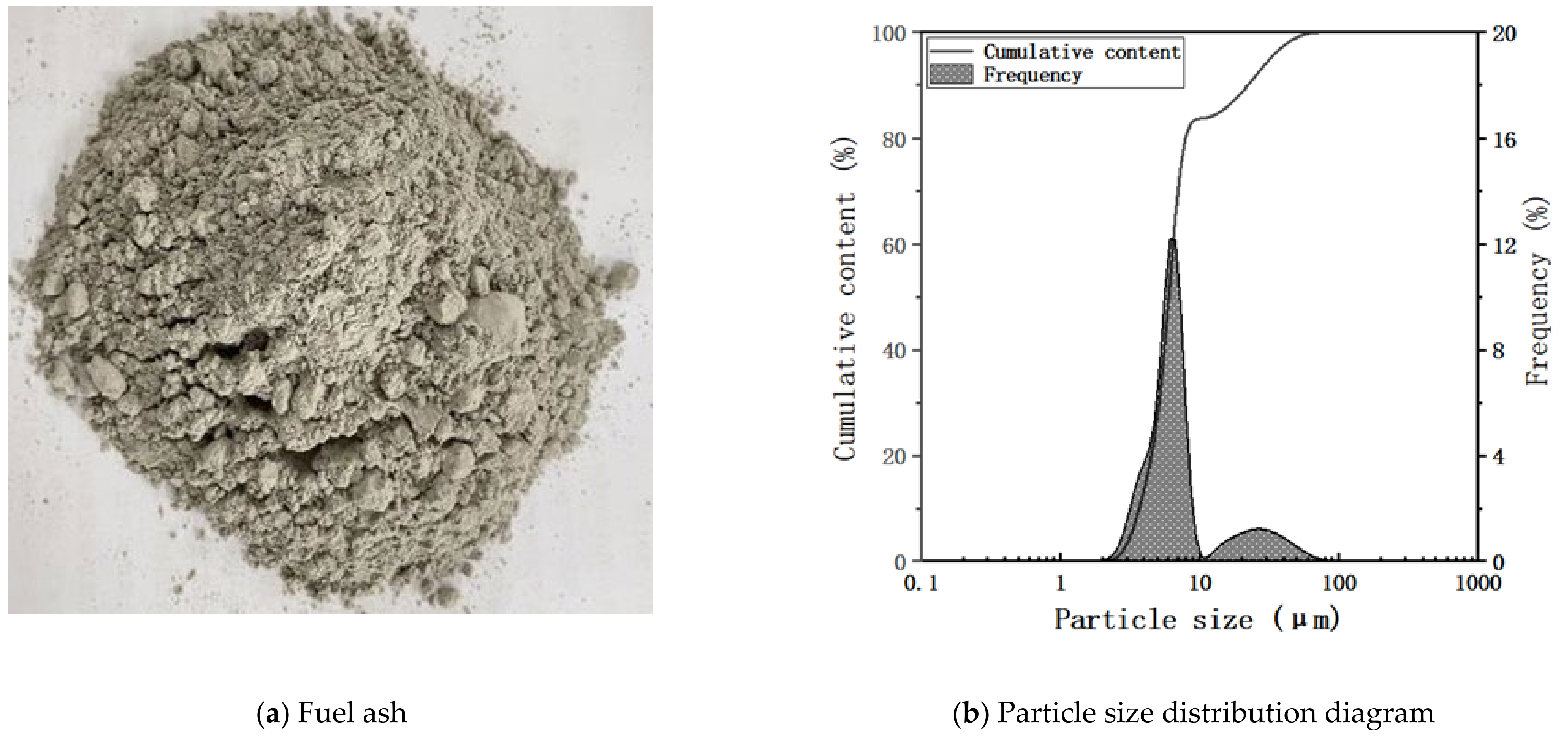
The fuel ash used in this study was sourced from Gongyi, Henan, China, and belonged to the second-class low-calcium category. It appeared as a gray powder, and particle size analysis revealed that particles smaller than 10 μm accounted for 83.7% of the sample while particles smaller than 100 μm accounted for 100%. Therefore, neither the MSWI fly ash nor the fuel ash required further grinding or particle size treatment [28]. The original samples and particle size distribution curves of both materials are shown in Figure 1 and Figure 2, respectively.
Table 1 shows the chemical compositions of the MSWI fly ash and fuel ash used in this study. As indicated, the MSWI fly ash had high contents of SiO2, CaO, and K2O while the fuel ash was mainly composed of SiO2, Al2O3, and CaO [29]. Table 2 displays the heavy metal content of the MSWI fly ash, revealing that it contained such heavy metals as Zn, Cd, Pb, and Cu. Notably, the Zn and Cd content exceeded the limit specified in the “Identification Standard for Leaching Toxicity of Hazardous Wastes”, indicating a certain level of hazard. The auxiliary materials used in this experiment, namely the foaming agent silicon carbide and the fluxing agent magnesium oxide, were both analytically pure.

2.2. Preparation Method of the FMC

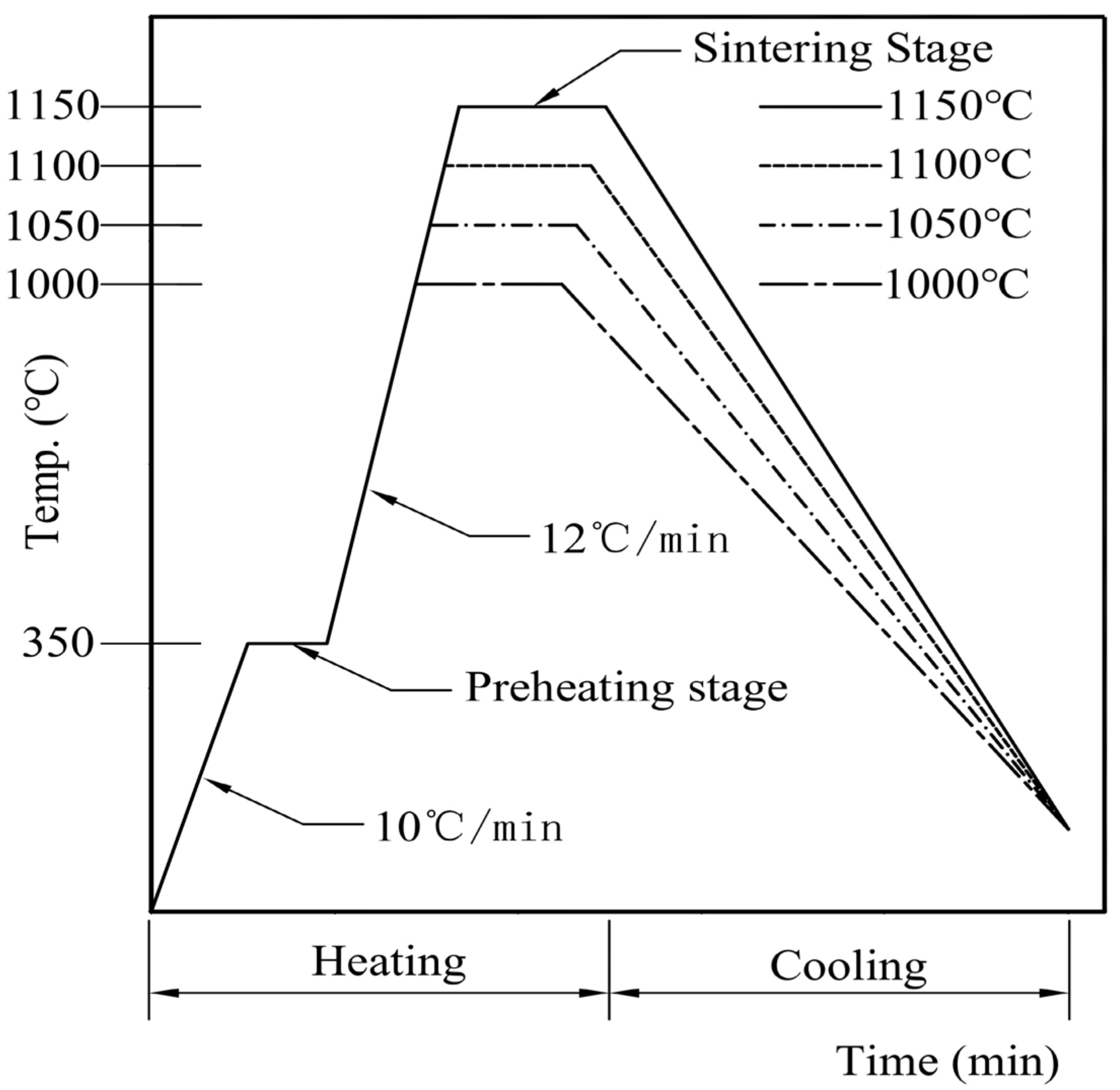
A flowsheet of the preparation process is shown in Figure 3. The detailed preparation process was as follows: Firstly, the dry MSWI fly ash and the fuel ash were weighed according to the designed mass ratio, and appropriate amounts of silicon carbide and magnesium oxide were added and uniformly mixed. Then, distilled water was added according to the water–solid ratio of 0.2~0.25, and the mixture was stirred with a magnetic stirrer and kneaded into 5–8 mm round particles using a manual ball-forming method. Sintering occurred, in accordance with the heating curve in Figure 4. The raw material ball was then put into a drying oven at 105 °C for 3 h to remove excess water. Next, the dried pellets were placed into an integrated muffle furnace and pre-heat-treated at a certain temperature for 20 min. After the temperature was raised to the set roasting temperature, the pellets were roasted for a certain period of time. In the raw material, 1 wt% of SiC was used as a foaming agent. Therefore, the following reaction would occur during the roasting stage [30]:
SiC + 2O2→SiO2 + CO2↑;
2SiC + 3O2→SiO2 + 2CO↑;
3Fe2O3 + C→Fe2O3 + CO2↑;
Fe2O3 + 3CO→2Fe + 3CO2↑.
The finished FMC was obtained by cooling the granules to room temperature, and its basic performance was measured.
The performance of FMC is directly related to preheating temperature; appropriate preheating can control gas production and soften the particles during the sintering stage [31]. However, excessively high preheating temperatures not only fail to effectively enhance the compressive strength of FMC [32] but also result in reduced expansion effects and increased production costs [33]. Therefore, considering the requirements for compressive strength and expansion effects and based on preliminary experiments [34], the preheating temperature was determined to be 350 °C, and the preheating time was set at 20 min.
As the FMC was intended to be used as a water treatment filter material, it was necessary for it to have a high porosity, a specific surface area, and a certain compressive strength. To explore the influences of various factors on the properties of FMC, for this study, single-factor experiments were designed based on MSWI fly ash content, roasting time, and roasting temperature and the controlled variable method was used to determine the appropriate parameters. To improve the adsorption performance of the ceramic aggregate and maximize the recycling proportions of the MSWI fly ash, these mixtures were designed as shown in Table 3.

2.3. Method for Measuring the Performance of the FMC

To ensure accuracy and consistency in the determination of the FMC properties, we followed the established measurement methods in CJ/T299-2008 and GB/T17431.2-2010 to measure the bulk density, porosity, hydrochloric acid solubility, and specific surface area of the FMC [35].
The specific surface area of the ceramic particles was measured using a fully automatic specific surface area and porosity analyzer (Model ASAP2460; MICROMERITICS Instrument CORP, Atlanta, USA). Before testing, the sample was physically crushed to less than 3 mm, and then, BET testing was used to test the specific surface area. The pore size distribution curve was obtained based on the BJH desorption branch-equivalent cylinder model. The calculation formula for specific surface area is:
P P 0 V 1 P P 0 = C 1 V m C × P P 0 + 1 V m C
where:
  • P—adsorbate partial pressure, PA;
  • P0—the saturated vapor pressure of the adsorbent, PA;
  • V—actual adsorption volume, cm3;
  • VM—the saturated adsorption volume of a single layer, cm3;
  • C—the BET constant.
The porosity was calculated with the following equation:
C p = m 0 m 1   m 1 × 100 %
where:
  • Cp—porosity;
  • m0—the weight of the ceramic aggregate sample before immersion, g;
  • m1—the weight of the ceramic particle sample after soaking in water for 2 h, g.
Additionally, we determined the compressive strength of the FMC using the measurement method proposed by Li [36]. Specifically, we calculated the average value of 15 single-granule FMC strength values. The single-granule strength value was determined using the following formula:
S = 4 P π x 2
where S is the compressive strength value of a single FMC (MPa); P is the load when the FMC is destroyed (N); and x is the particle size (mm) of a single FMC.
To determine the concentration of heavy metal leaching, the experimental protocol in this paper followed the guidelines provided in HJ557-2010, the “Solid Waste Leaching Toxicity Leaching Method-Horizontal Vibration Method” [37,38], and GB/T5085.3-2007, “Hazardous Waste Identification Standard Leaching Toxicity Identification” [24,39]. The FMC samples were initially crushed to pass through a 3 mm hole sieve. Then, 20~100 g of FCM sample was weighed, put in a pre-dried container with a cover, and dried at 105 °C with a constant weight of ±0.01 g; then, the moisture content of the sample was calculated. Subsequently, 20 g of the dried sample (on a dry basis) was added to an extraction container along with 200 mL of extractant to attain a liquid–solid ratio of 10:1 (L/Kg). The extraction container was fixed vertically onto a horizontal oscillator and subjected to an oscillation frequency of 120 times/min and an amplitude of 40 mm at room temperature for 8 h. After the sample was allowed to stand for 16 h, the leachate was filtered, collected, and analyzed for heavy metal concentration using an inductively coupled plasma mass spectrometer (Model NexION 2000; Perkin Elmer GmbH, USA). A total of 25 mL of solid waste leaching solution was taken, and 5.0 mL of nitric acid (ρ = 1.42 g/mL, premium pure) was added. This was put into the digestion tank, and 4 mL of nitric acid (ρ = 1.42 g/mL, premium pure) and 1 mL of hydrochloric acid (ρ = 1.19 g/mL, premium pure) were added; then, microwave digestion was conducted, the acid was removed at 150 °C, the solution was transferred into a 50 mL volumetric flask, pure water was used for the constant volume, and the supernatant was taken for use of ICP-MS for determination.

2.4. Characterization of Microstructure

The internal porous structure and composition of the FMC were examined through the use of scanning electron microscopy (SEM) [27,40,41]. To prepare the sample for observation, the FMC was initially crushed, and then its surface was polished and coated with gold to enhance its conductivity. The sample was then observed under SEM (Model S-3700N; Cabinet Valley Technology Development (Shanghai) Co., Ltd., China) at a magnification of 2000×, with an acceleration voltage of 15 kV and a working distance of 10 mm, to investigate its microstructure.
To determine the phase composition of the FMC powder sample, the material was ground to pass through a 200-mesh sieve and subjected to analysis with an X-ray diffractometer (XRD). The XRD (Model SmartLab-9; Rigaku, Japan) instrument used a Cu target, with a voltage of 40 kV and a current of 100 mA. The angle range of the scan was 10 to 90°, and the scanning speed was set at 5°/min. The obtained XRD data were then analyzed with Jade 6.0 software [18]. Through this method, we identified the raw materials used for the FMC, as well as the phase compositions of the samples at different temperatures.

2.5. Determination of the Ability of the FMC to Remove Ammonia and Nitrogen

Samples of different materials, namely zeolite, commercial FMC, and homemade FMC, were weighed and soaked in deionized water. After rinsing and drying at 105 °C until a constant weight was reached, the samples were crushed to pass through a 20-mesh sieve. Subsequently, 5.0 g of each sample was transferred to a 100 mL container. The container was then stoppered with an Erlenmeyer flask, and 50.0 mL of an ammonia nitrogen solution with a concentration of 5.0 mg/L was added. The flask was placed on a constant temperature shaker (Model THZ-82; Jintan Jingda Instrument manufacturing factory, Jiangsu, China) and shaken at a speed of approximately 150 r/min for 24 h at room temperature. Following the 24 h shaking period, the supernatant was collected and filtered through a 0.45 μm filter. The concentration of N H 4 + -N in the resulting solution was then determined via the salicylic acid–hypochlorite photometric method using an ultraviolet-visible spectrophotometer (Model TU-1810; Beijing Puxie General Instrument Co., Ltd., Beijing, China) [42]. The removal rate of the ammonia nitrogen was subsequently calculated based on the concentration change and using the following formula [35,39]:
Removal   rate % = C 0 C t C 0 100 %
In this equation, C0 is the initial concentration of the ammonia nitrogen solution and Ct is the equilibrium concentration of the ammonia nitrogen solution.
After the sample was allowed to settle for one hour, the absorbance was measured at a wavelength of 697 nm, using a cuvette with an optical path of 10 mm. Water was used as a reference, and the sample’s absorbance was subtracted from the blank tube’s absorbance to obtain the corrected absorbance.
The corrected absorbance values were then used to plot a calibration curve between the ammonia nitrogen content (μm) and the corrected absorbance, resulting in a linear equation of y = 9.3953x − 0.17, with an R2 value of 0.991. The calibration curve is presented in Figure 5.

3. Test Results and Analysis

3.1. The Optimization of Fly Ash Content

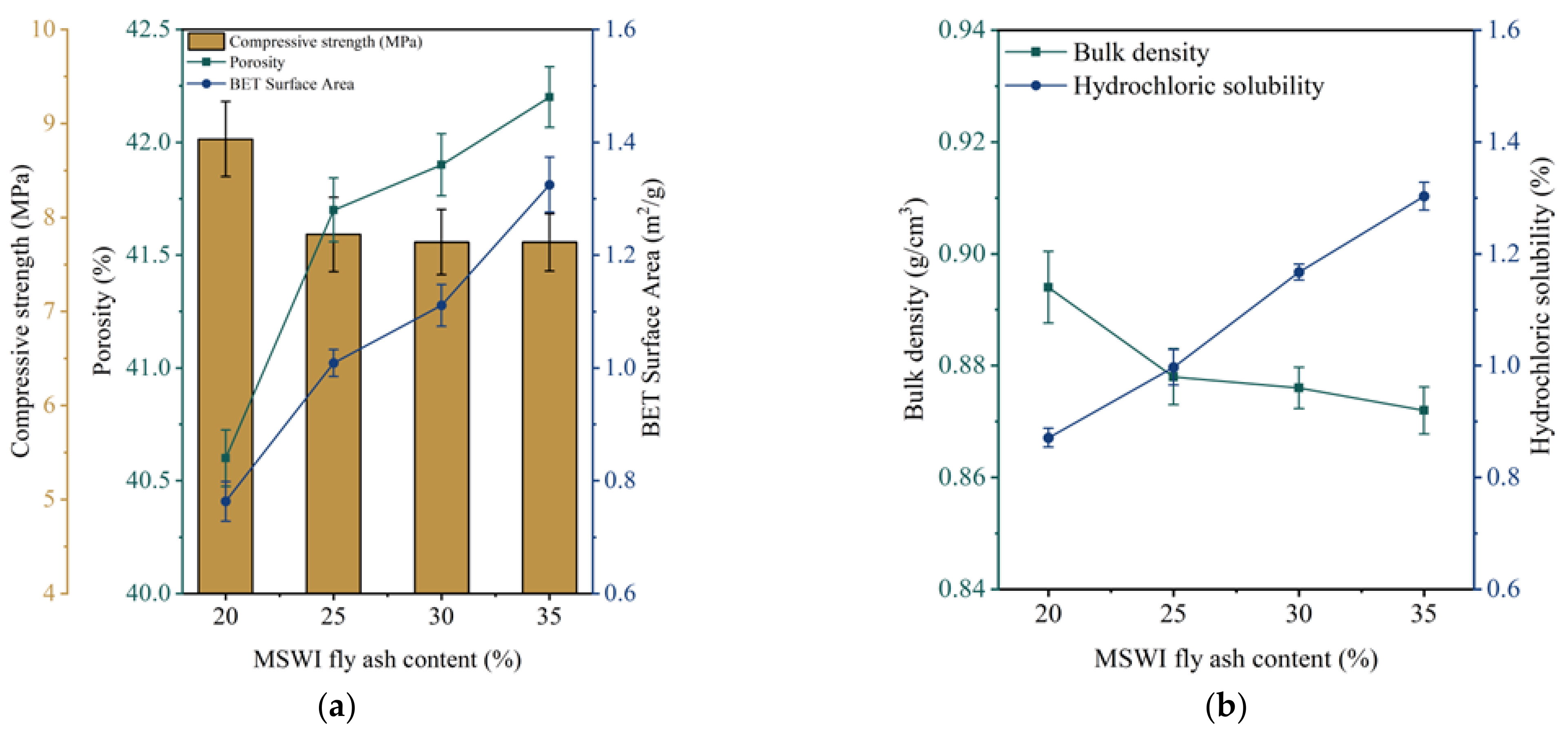
In order to investigate the effects of different MSWI fly ash contents on the physical properties of FMC, the M20Ti20Te150, M20Ti25Te150, M20Ti30Te150, and M20Ti35Te150 groups were selected for testing. The hydrochloric acid solubility, porosity, and specific surface area of the FMC are shown in Figure 6a,b. The results indicate that these factors are positively correlated with the amount of MSWI fly ash added. This can be attributed to the volatilization of the heavy metal oxides in the fly ash into heavy metal chloride gases and the decomposition of carbonates into CO2 during sintering [18,43], while the viscous glass phase inside the FMC inhibited the escape of gases. When the FMC cooled, the trapped gases led to the formation of abundant pores, increasing the porosity and the specific surface area. A larger specific surface area provides a larger contact area for hydrochloric acid, leading to an increase in solubility. The bulk density and compressive strength of the FMC are also shown in Figure 6a,b. The results indicate that the bulk density and compressive strength of the FMC are negatively correlated with the amount of MSWI fly ash added. This can be attributed to the decrease in bulk density due to the increase in porosity and the consequent decrease in specific gravity. A high amount of MSWI fly ash led to a decrease in the relative content of the alumino-silicates in the FMC, which was unfavorable for the glass formation phase and reduced the interconnection between the crystals, ultimately decreasing the compactness of the internal material and the compressive strength of the FMC [31]. When the MSWI fly ash content was 35%, the properties of the FMC (with a bulk density of 872 kg/m3, a hydrochloric acid solubility rate of 1.3%, a porosity of 42.2%, a specific surface area of 1.3 m2/g, and a compressive strength of 7.6 MPa) still met the requirements of CJ/T299-2008. Therefore, in order to maximize the utilization of solid waste, the optimal MSWI fly ash content for FMC was determined to be 35%.

3.2. The Influence and Determination of Roasting Time

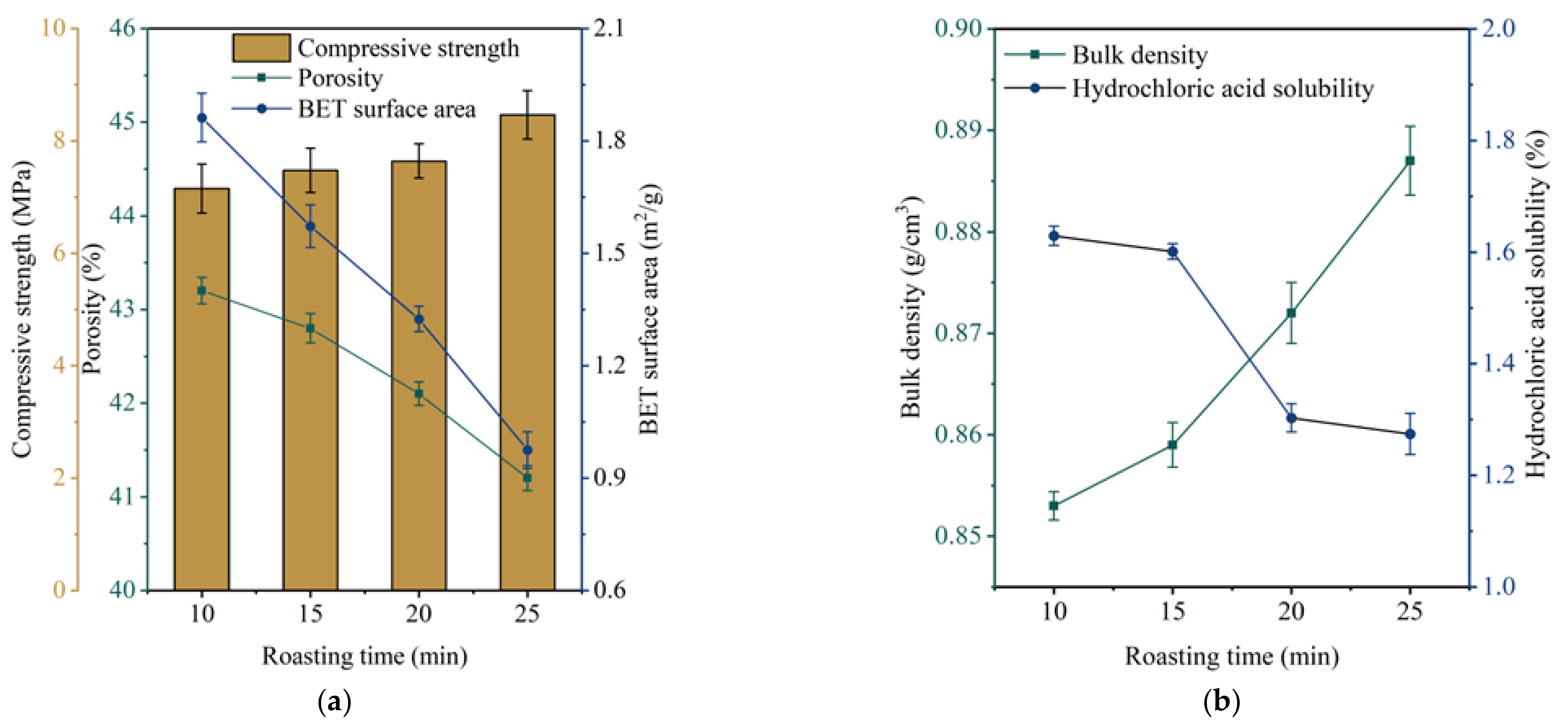
When the sintering time is too short, ceramic aggregate may not undergo complete gasification, whereas an excessively long sintering time is not conducive to energy conservation. To optimize the roasting and roasting system, the M35Ti10Te150, M35Ti15Te150, M35Ti20Te150, and M35Ti25Te150 groups were selected for testing. The experimental results are presented in Figure 7.
As shown in Figure 7, increasing the calcination time from 10 min to 25 min resulted in a continuous increase in the bulk density of the ceramic aggregate, whereas the hydrochloric acid solubility, porosity, and specific surface area gradually decreased. Conversely, the compressive strength of the FMC gradually increased.
Figure 7b shows that prolonging the roasting time increased the liquid phase generated by the melting of the FMC billet, which filled the internal pores of the FMC and increased its shrinkage and bulk density. Furthermore, as the liquid-phase content increased, the FMC became denser and more solid, resulting in a reduced contact surface area for acid and a lower hydrochloric acid solubility rate [34]. Figure 7a indicates that increasing the specific gravity of the FMC led to a corresponding increase in its density, which caused the porosity to decrease continuously [28]. Increasing the roasting time also promoted the formation of a liquid-phase package on the surface of the FMC, leading to the creation of airtight pores that gradually increased the compressive strength of the FMC. However, the specific surface area decreased as the number of liquid phases increased and the pores become filled.
The hydrochloric acid solubility rates of the FMC under different roasting times were found to be less than 2%, meeting the requirements for “Water Treatment Artificial Ceramic Aggregate Filter Material.” Moreover, the porosity of the FMC was higher than 40% and the specific surface area exceeded 0.5 m2/g, while the FMC also exhibited a certain compressive strength. Among the various roasting times considered, a 10 min roasting time produced a minimum bulk density of 853 kg/m3, a maximum porosity of 43.2%, and a specific surface area of 1.9 m2/g. Additionally, the compressive strength reached 7.2 MPa, which exceeds 5.3 MPa, meeting the requirements of superior FMC. Therefore, taking into account both the energy conservation and the basic properties of the FMC, the optimal roasting time was determined to be 10 min.

3.3. The Influence and Determination of Roasting Temperature

Based on the MSWI fly ash content and the roasting time determined in Section 3.1 and Section 3.2, the M35Ti10Te0, M35Ti10Te50, M35Ti10Te100, and M35Ti10Te150 groups for testing were selected, and the experimental results are shown in Figure 8.
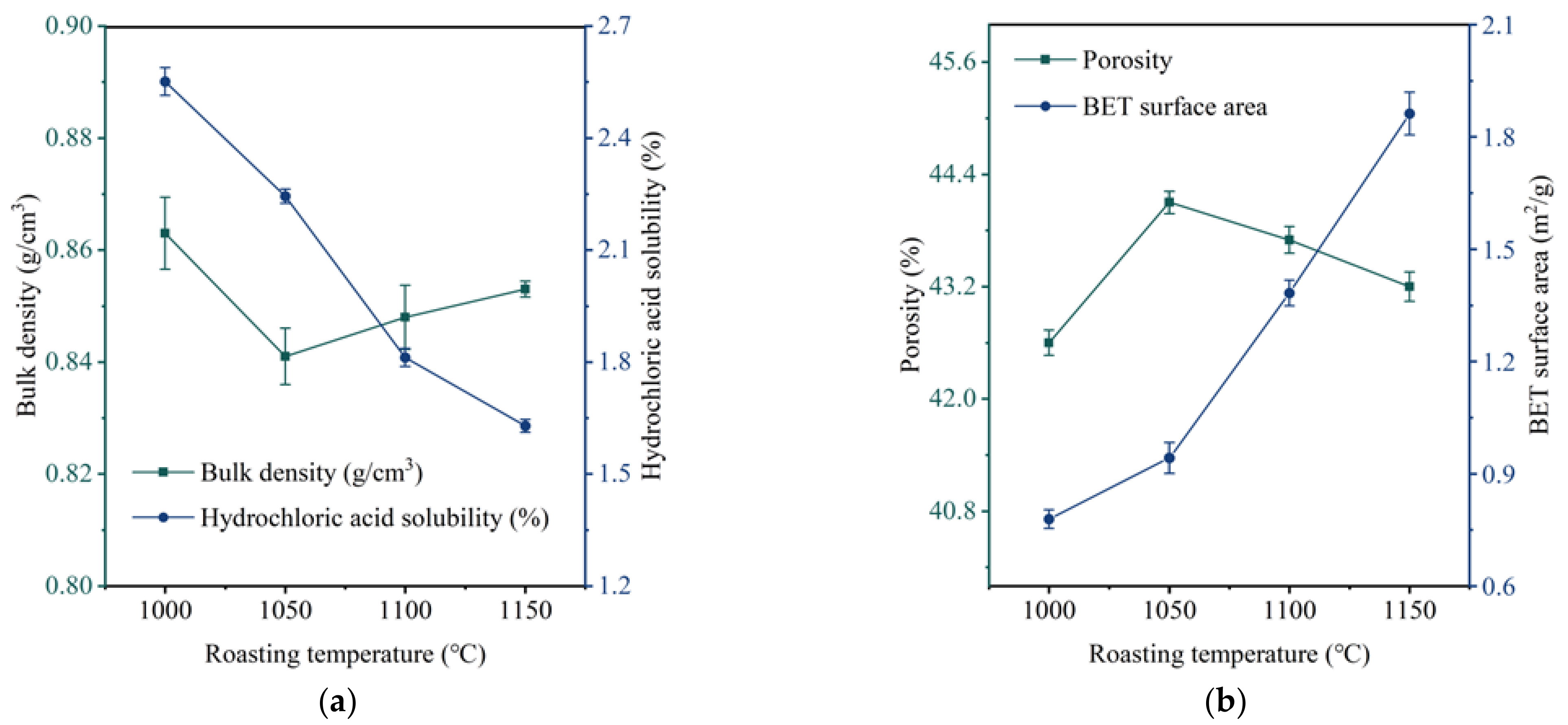
As shown in Figure 8, the bulk density of the FMC first decreased and then increased as the roasting temperature increased from 1000 °C to 1150 °C. The hydrochloric acid solubility rate decreased, the void ratio first increased and then decreased, and the specific surface area and compressive strength kept increasing.
From Figure 8a, the bulk density decreased as the roasting temperature increased from 1000 °C to 1050 °C. This is because more substances in the FMC blank were burned out as the temperature increased, and some of the gases generated became ash, reducing the weight of the FMC. Additionally, the volume of the FMC expanded and became larger due to the gas generated, leading to a decrease in bulk density and an increase in porosity [44]. When the roasting temperature increased from 1050 °C to 1150 °C, a liquid phase started to appear in the FMC, and it gradually increased and flowed into the FMC to fill the pore structure, resulting in a decrease in the pore volume and an increase in the density of the FMC [20,31,45]. As the density increased, the porosity decreased [40]. On one hand, as the liquid phase increased, the FMC became denser, reducing its contact surface for acid and leading to a decrease in the hydrochloric acid solubility rate. On the other hand, the acid-soluble components increased with the temperature. The high sintering component was poorly soluble, which resulted in a reduced hydrochloric acid solubility rate. The hydrochloric acid dissolution rate conformed to Chinese national industrial standard CJ/T 299-2008.
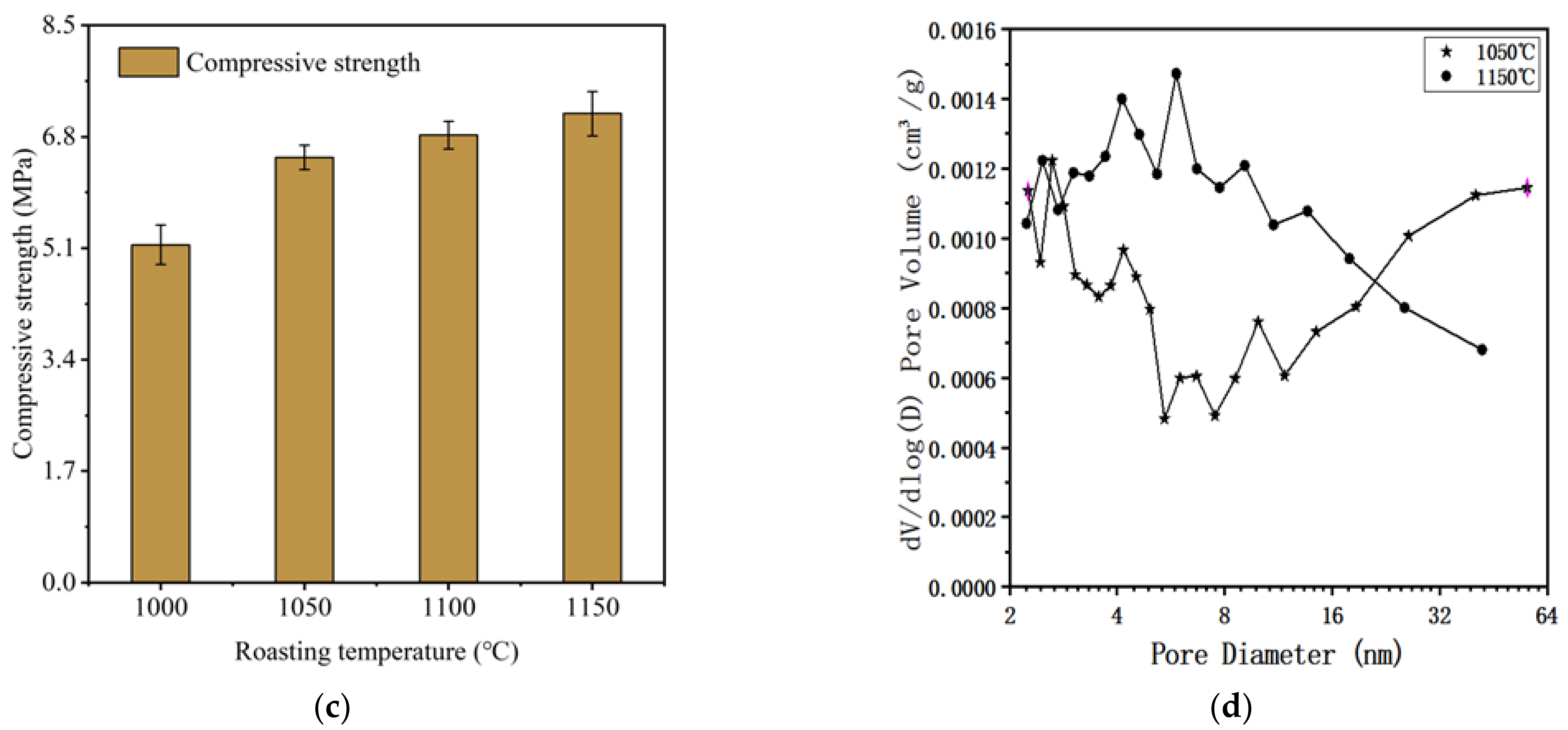
Research has shown that the size, shape, and uniformity of pores have a certain effect on the performance of FMC. As shown in Figure 8b,d, the specific surface area increased from 0.7790 m2/g to 1.9 m2/g with an increase in temperature. This is because during the process from 1000 °C to 1050 °C, the gas generated in the FMC mostly formed mesopores or macropores, with no small pores or micropores. In the process from 1050 °C to 1150 °C, the liquid phase increased to fill some of the large pores and make the surface compact [40]. The sealing effect prevented the gas from escaping, but the increase in the gas generated increased the internal pressure of the FMC, leading to more pores being produced inside the FMC [46]. The pores continued to increase, and the pore size and depth also increased, resulting in an increase in the specific surface area.
Figure 8c shows that as the temperature increased, the number of liquid phases increased, making the FMC denser and increasing its compressive strength [31]. However, there was no significant change in the compressive strength from 1050 °C to 1150 °C. The pore size distribution diagram of the FMC, in Figure 8d, shows that when the roasting temperature of the ceramic aggregates increased from 1050 °C to 1150 °C, the numbers of macropores in the ceramic aggregates decreased while the numbers of mesopores increased. As a result, the specific surface area gradually increased with the increase in temperature, with no significant impact on the compressive strength.
To ensure that the basic properties of the FMC met the requirements, a roasting temperature of 1150 °C was chosen.

3.4. Analysis of the FMC Morphology

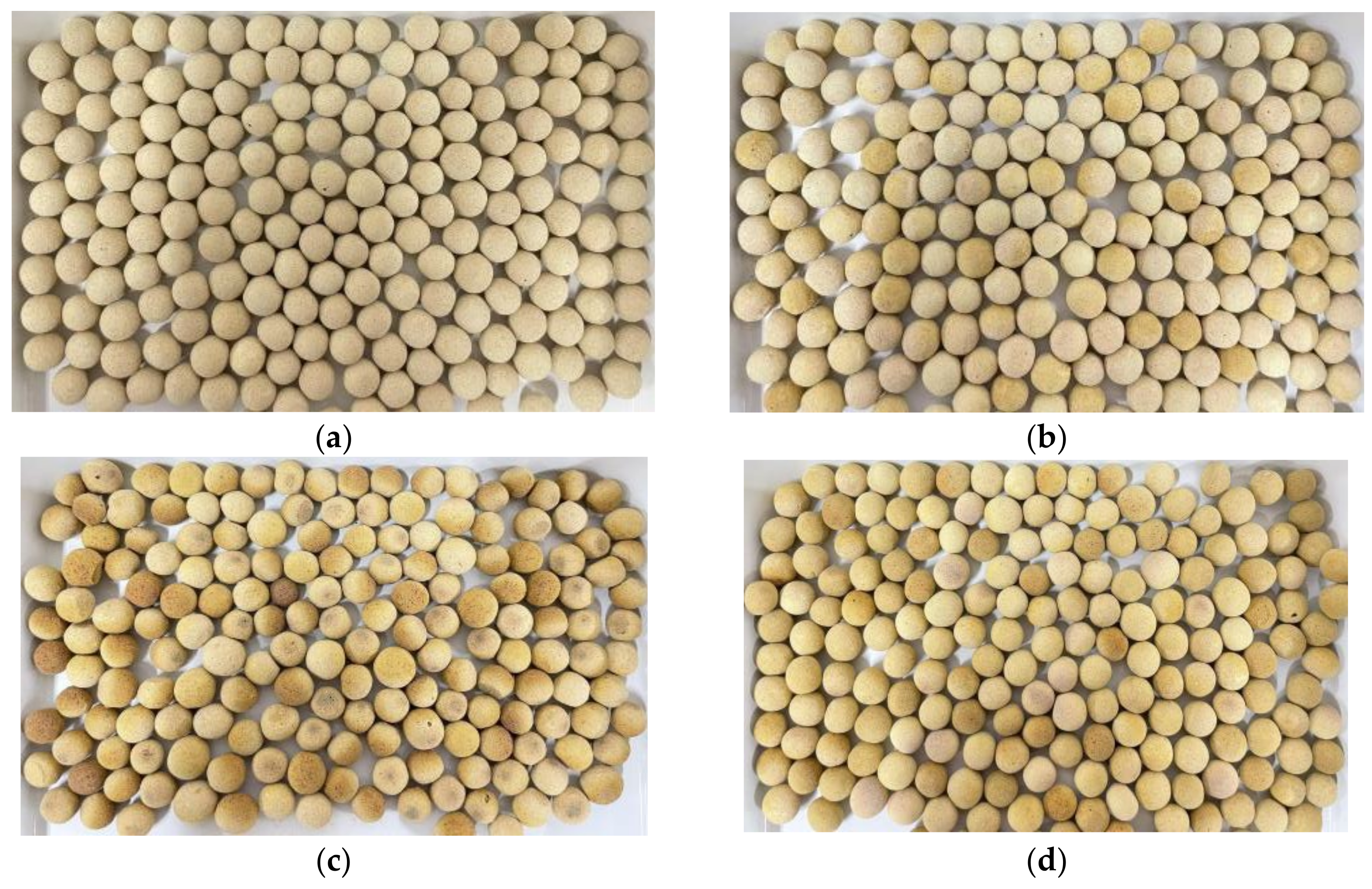
Based on Figure 9, it is evident that the surface of the heat-treated FMC became progressively darker with the increasing roasting temperature. Furthermore, a glaze layer formed on the surface [31]. (a) The FMC fired at 1000 °C had a light yellow color, no significant expansion in volume, and a very low compressive strength and turned mostly into powder after crushing; (b) the color of the FMC fired at 1050 °C was slightly darker, with a certain expansion in roasting volume and an increased compressive strength; (c) at 1100 °C, the FMC was yellow, with a slight reduction in the heat treatment volume and a further increased compressive strength; (d) and when heated at 1150 °C, the FMC became an even darker yellow, experienced volume shrinkage, and exhibited decreased compressive strength, forming small lumps after crushing.

3.5. Analysis of Ammonia Nitrogen Removal Effect

It can be seen from Figure 10a that when the MSWI fly ash content increased from 20% to 35%, the removal rate of ammonia nitrogen gradually increased, and when the content was 35%, the removal rate was 49.3%. The increase in the removal rate had a necessary connection with the continuous increase in the specific surface area. The increase in the MSWI fly ash content produced more gas during the high-temperature roasting process, increasing the internal pores. The specific surface area increased as the gas escape formed pores. When the Figure 10a MSWI fly ash content is compared to the ammonia nitrogen, the removal rate and the change in the specific surface area are roughly the same. The more pores are formed in the preparation process of FMC, the more N H 4 + -N attachment points there are, and the higher the ammonia nitrogen removal rate is.
As shown in Figure 10b, with the extension of the roasting time, the removal rate of the ammonia nitrogen gradually decreased. When the roasting time was 10 min, the maximum removal rate was 61.032%. The specific surface area decreased as the number of liquid phases increased and the pores are filled, and the removal rate also decreased. The accumulation of micropores and small pores in the FMC increased the specific surface area and increased the removal rate. Furthermore, it can be seen from Figure 10c that when the temperature rose from 1000 °C to 1150 °C, the removal rate of the ammonia nitrogen gradually increased. This is due to the increase in specific surface area caused by the increase in small pores inside the FMC, as well as the increases in pore diameter and depth and the change in the pore channels from disconnection to interconnection. As a result, the FMC had more attachment points for N H 4 + -N, which led to an increase in the removal rate. When the temperature was 1150 °C, the removal rate reached its highest value, of 61.0%.
In summary, the removal rate of ammonia nitrogen is affected by MSWI fly ash content, roasting time, and roasting temperature. The optimal conditions for preparing FMCs with high ammonia nitrogen removal rates are as follows: a MSWI fly ash content of 35%, a roasting time of 10 min, and a roasting temperature of 1150 °C. Under these conditions, the removal rate of the ammonia nitrogen reached 61.0%, which meets the requirements for artificial FMC materials for water treatment.
Figure 10d presents a comparison of the N H 4 + -N removal capacities among different samples, including homemade FMCs heat-treated at different calcination temperatures, purchased zeolite, and commercial FMC. The results show that the ammonia nitrogen removal rate of the commercial FMC was the highest, reaching 66.2%, while the zeolite had a relatively low removal rate of 44.6%. Among the four groups of homemade FMCs, the removal rate of the FMC roasted at 1000 °C was the lowest, while the removal rates of the other three groups were higher than that of the zeolite. The highest removal rate for the homemade FMC was achieved by the group heat-treated at 1150 °C, with a removal rate of 61.0%, which is only 5.2% lower than that of the commercial FMC. It is worth noting that the compressive strength of the commercial FMC was 6.3 MPa, which is lower than that of the FMC heat-treated at 1150 °C. Overall, the homemade FMC heat-treated at 1150 °C had good potential for application as an artificial FMC material for water treatment, with a high removal rate and adequate compressive strength.

3.6. Adsorption Mechanism of the FMC

3.6.1. Mineral Composition

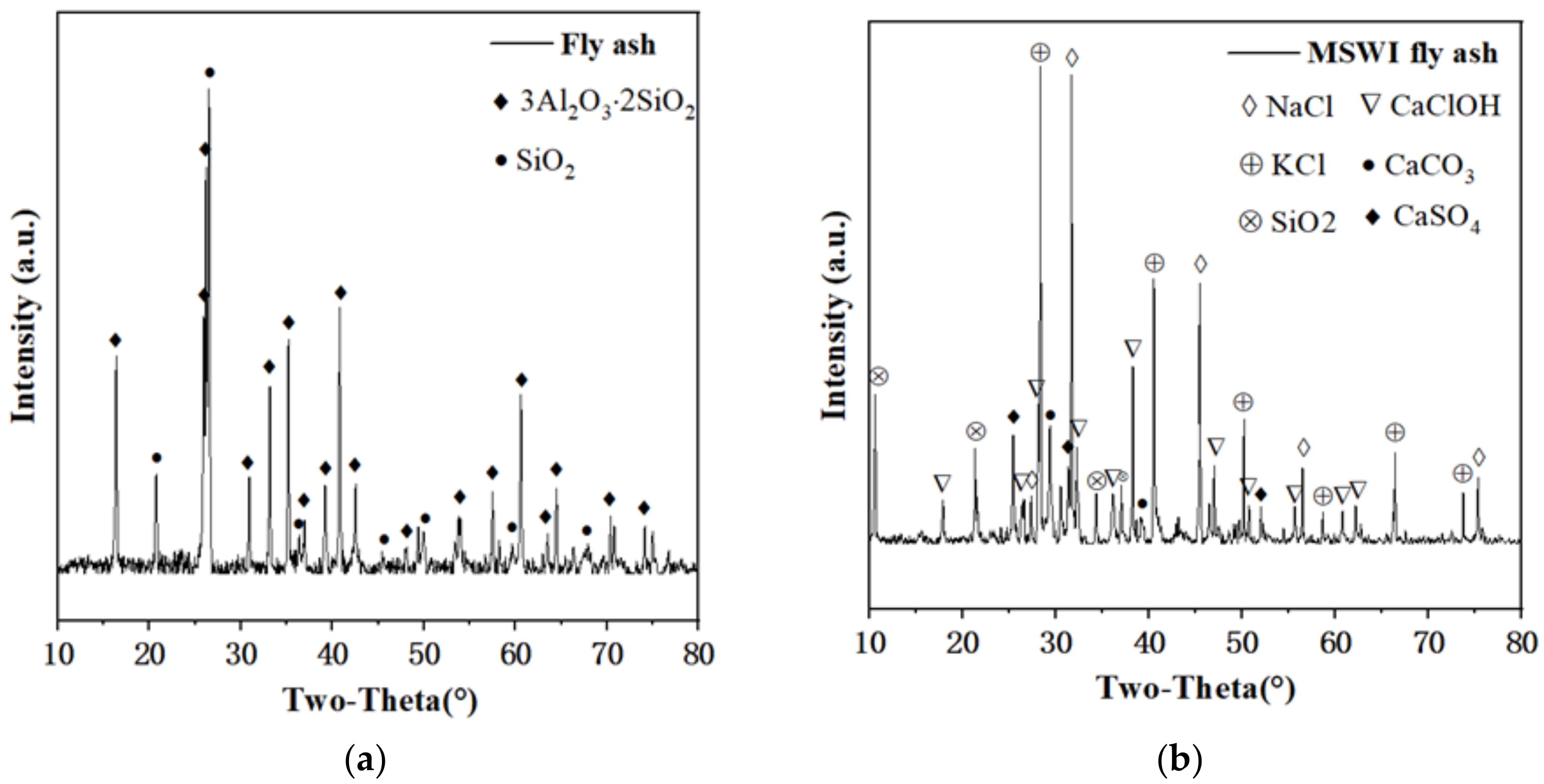
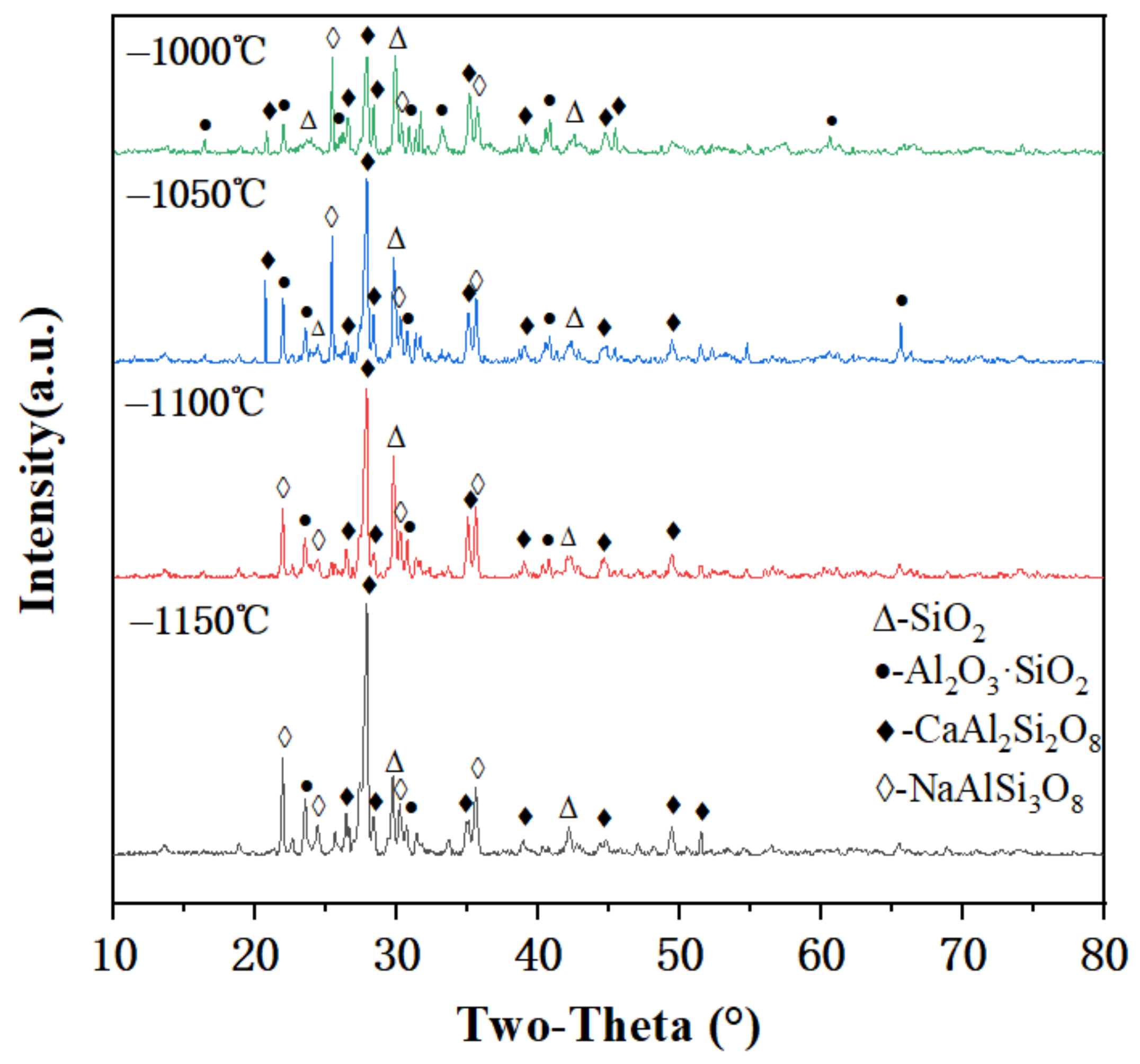
The mineral phase results of the raw materials and the FMC, as determined with an XRD, are shown in Figure 11 and Figure 12. It can be clearly observed that the main mineral phases in the fly ash were mullite and quartz, while the composition of the MSWI fly ash was more complex, mainly consisting of various chlorides and calcium oxides. The primary mineral phases in the FMC were quartz, mullite, sodium feldspar, and calcium feldspar. During the sintering temperature increase from 1000 °C to 1150 °C, some fusible substances melted to form a glass phase and combined with partially molten quartz to form feldspar minerals, causing the intensity of the quartz diffraction peaks to gradually decrease and the intensity of the feldspar diffraction peaks to gradually increase. The feldspar materials were distributed in a network-like manner, which not only formed a robust skeletal structure that enhanced the strength of the FMC [47] but also provided space for the embedding of cations into the FMC matrix [48]. From 1000 °C to 1100 °C, the original mullite in the fuel ash gradually melted, resulting in a decrease in the intensity of the mullite diffraction peaks; when the temperature increased from 1100 °C to 1150 °C, the amounts of molten substances, such as SiO2 and Al2O3, increased, and the newly formed mullite crystals caused the intensities of their diffraction peaks to grow larger. In addition, the Ca2+ ions contained in the anorthite and albite provided active sites for the FMC to adsorb N H 4 + , which helped to improve its ammonia removal effect [24,39].

3.6.2. Microstructure

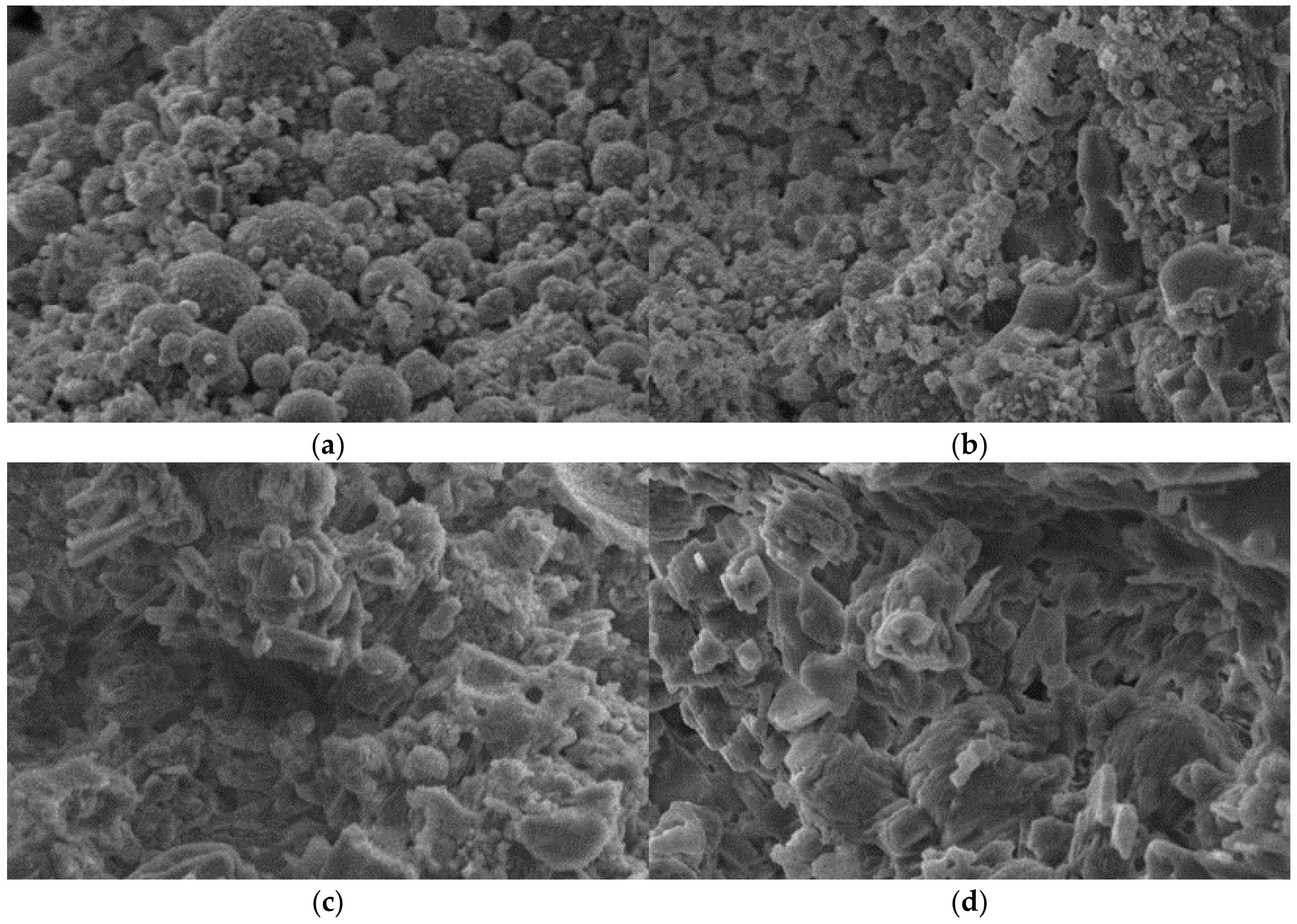
The microstructure of the FMC was observed using SEM, as shown in Figure 13. It is apparent that the microstructure of the FMC underwent significant changes as the temperature increased. At 1000 °C, the FMC exhibited a loosely packed state, and the sintering reaction was incomplete. However, as the temperature was increased from 1000 °C to 1150 °C, various pores of different sizes were observed within the FMC. The formation of a porous structure in FMC is mainly attributed to the effect of gas volatilization at high temperatures and the formation of a liquid phase in the FMC [45]. Different temperatures lead to different rates and amounts of gas generated inside FMC, resulting in uneven pore sizes [35,49]. The larger the pore size, the lower the density and strength of the FMC. Conversely, the smaller the pore size, the higher the strength. Therefore, reducing the pore size can improve the strength of FMC, and this effect is consistent with the impact of sintering temperature on strength [28]. As sintering temperature increases, pore size gradually decreases, indicating that formation of more small pores and micropores is favored and contributes to an increase in specific surface area. This finding is consistent with the conclusion that the specific surface area of FMC increases with sintering temperature. In particular, Figure 10d displays that the microstructure of the FMC was rich in pores, presenting a loose, rod-like, sponge-like structure across the entire cross-section. The majority of the pore diameters were smaller than 16 nm, which indicates that the material possessed a desirable specific surface area and could provide more channels and adsorption sites for adsorption processes [24].
Figure 14 shows that the porosities and specific surface areas of FMC products prepared at different calcination temperatures exhibited little change, while the range of ammonia nitrogen removal rates is relatively apparent. This phenomenon can be attributed to the fact that higher calcination temperature can melt more quartz and form new albite and anorthite crystals with other eutectic substances. The adsorption of ammonia nitrogen ions by FMC is not entirely dependent on the large specific surface area but also depends on the ion exchange where N H 4 + enters the FMC to exchange with Ca2+ in anorthite [50] (the exchange equation is shown next). N H 4 + + Ca anorthite→NH4- anorthite + Ca2+.
More albite and anorthite crystals provide more binding sites for adsorption of ammonia nitrogen ions, resulting in a significant increase in ammonia nitrogen removal rate even when the void ratio and specific surface area exhibit little change [25]. Therefore, ion exchange plays a dominant role in the adsorption process.
The aforementioned adsorption mechanisms include two stages: ion embedding and ion exchange. In the first stage, ammonium ions enter an FMC and are captured by its porous structure. In the second stage, some of the captured ammonium ions undergo ion exchange with cations on feldspar. Ammonium ions in the aqueous phase are immobilized in a monolayer of the solid phase. Both the physical and chemical adsorption processes occur spontaneously. A schematic diagram of the adsorption mechanism of FMC is shown in Figure 15.

3.7. Analysis of the Leaching Effect of Heavy Metals

After tests were conducted on the basic properties of FMCs prepared with different MSWI fly ash contents, roasting times, and roasting temperatures, as well as the N H 4 + -N removal rates measured, it is evident that heating temperature has a significant impact on the performance of FMC. Therefore, experiments were conducted to measure the leaching effects of heavy metals at different heating temperatures. The results of these experiments are presented in Table 4. Additionally, we conducted a heavy metal leaching test on the original MSWI fly ash, the results of which are shown in Table 5. As indicated by the results in Table 5, the leaching amounts of the Zn and Cd elements in the untreated MSWI fly ash exceeded the limits stipulated in Chinese standard GB8978-1996.
The use of MSWI fly ash as a raw material to produce FMC with the potential to solidify heavy metals is a crucial aspect of waste resource utilization. In this study, a leaching solution prepared in accordance with HJ557-2010, the “Solid Waste Leaching Toxicity Leaching Method-Horizontal Oscillation Method”, was used to measure the heavy metal leaching concentration of FMCs heat-treated at four roasting temperatures using inductively coupled plasma mass spectrometry. The results in Table 4 indicate that the leaching concentrations of Zn, Cd, Pb, and Cu in the FMC were significantly lower than the limits specified in GB8978-1996, the “Comprehensive standards for sewage discharge”. This suggests that FMC effectively solidifies heavy metals in MSWI fly ash, is environmentally safe, and does not cause secondary pollution during sewage treatment [31,39].
Moreover, it is evident that with increasing calcination temperature, the leaching concentrations of Cd, Pb, and Cu gradually decreased, indicating a better solidification effect. However, the leaching concentration of Zn did not decrease with the increasing temperature. This observation is attributed to the replacement of part of the Ca2+ and Al3+ in the silicate mineral by heavy metals and the network lattice of the silicate [31]. Overall, the results indicate that FMC produced from MSWI fly ash is effective in solidifying heavy metals and has good environmental safety.

4. Conclusions and Perspectives

4.1. Conclusions

In this study, an FMC with high ammonium nitrogen adsorption and high porosity was successfully prepared using MSWI fly ash and fuel ash. The effects of MSWI fly ash content, roasting time, and roasting temperature on the adsorption performance, microstructure, and crystal phases of the FMC were investigated. It was proven that FMC prepared using solid wastes such as MSWI fly ash not only exhibits good performance but also reduces reliance on natural minerals. The following conclusions can be drawn from these experiments:
(1)
The optimal formulation for preparing FMCs is MSWI fly ash:fuel ash:silicon carbide:magnesium oxide = 35:63:1:1. Under the optimal sintering conditions determined with the single-factor experiments, an FMC with high ammonium nitrogen adsorption and high porosity can be obtained. The sintering conditions are as follows: preheating temperature, 350°C; preheating time, 20 min; sintering temperature, 1150 °C; and sintering time, 10 min.
(2)
XRD analysis indicated that the main minerals in the FMC were sodium feldspar, calcium feldspar, and mullite. The Ca2+ in the feldspar crystals of the FMC provided a large number of active sites for N H 4 + ion exchange. SEM analysis showed that a structure dominated by small pores was formed inside the FMC during sintering; this could encapsulate heavy metal ions for heavy metal fixation and immobilize N H 4 + through ion embedding. Ion exchange plays a dominant role in the adsorption process.
(3)
The ammonium nitrogen adsorption rate of the FMC prepared in this study reached up to 61.0%. Ammonium nitrate can be used as an FMC material, and the ammonium nitrogen removal capacity of the resulting FMC will be superior to that of zeolite and comparable to that of commercial FMC; moreover, the compressive strength of the FMC in our study was 7.7 MPa, the porosity was 43.2%, the specific surface area was 1.9 m2/g, the hydrochloric acid solubility rate was 1.6%, and the bulk density was 853.0 kg/m3, all of which meet the Chinese national standards (CJ/T299-2008).
(4)
The leaching concentrations of Zn, Cd, and Cu were 0.00155 mg/L, 0.00033 mg/L, and 0.00047 mg/L, respectively, while Pb was not detected. The heavy metal concentrations complied with the Chinese national standards (GB8978-1996), indicating that MSWI fly-ash-based FMC is a safe adsorbent material.

4.2. Perspectives

The transformation of MSWI fly ash into industrial products is gaining increasing attention. To encourage the use of MSWI fly ash as a raw material for ceramic particles, future research should focus on the following points:
(1)
A quantitative study of the relationship between the porosity of MSWI fly ash ceramic particles and their adsorption capacity;
(2)
A quantitative study of the relationships between pore characteristics of MSWI fly ash ceramics and sintering temperature;
(3)
A quantitative study of the relationships between crystal phase variations and sintering temperature in MSWI fly ash ceramics;
(4)
A quantitative study on the relationship between the specific surface area of MSWI fly ash ceramics and sintering temperature;
(5)
Quantitative research of the relationship between heavy metal migration and sintering temperature in MSWI fly ash ceramics.

Author Contributions

Investigation, writing—original draft, data curation, N.L.; project administration, conceptualization, methodology, resources, validation, funding acquisition, H.C. and J.C.; supervision, writing—review and editing, Y.-F.C. All authors have read and agreed to the published version of the manuscript.

Funding

This project received no external funding.

Data Availability Statement

Data are contained within the article.

Conflicts of Interest

The authors declare no conflict of interest.

References

  1. Nanda, S.; Berruti, F. Municipal solid waste management and landfilling technologies: A review. Environ. Chem. Lett. 2020, 19, 1433–1456. [Google Scholar] [CrossRef]
  2. Chang, F.-Y.; Wey, M.-Y. Comparison of the characteristics of bottom and fly ashes generated from various incineration processes. J. Hazard. Mater. 2006, 138, 594–603. [Google Scholar] [CrossRef] [PubMed]
  3. Quina, M.J.; Bordado, J.M.; Quinta-Ferreira, R.M. Recycling of air pollution control residues from municipal solid waste incineration into lightweight aggregates. Waste Manag. 2014, 34, 430–438. [Google Scholar] [CrossRef] [PubMed] [Green Version]
  4. Fedje, K.K.; Andersson, S. Zinc recovery from waste-to-energy fly ash—A pilot test study. Waste Manag. 2020, 118, 90–98. [Google Scholar] [CrossRef]
  5. Sun, H.; Wu, W.; Zhao, Y.; Lin, Y.; Xu, S.; Zhang, T.; Zhang, X.; Xing, F.; Ren, J. Mechanical and durability properties of blended OPC mortar modified by low-carbon belite (C2S) nanoparticles. J. Clean. Prod. 2021, 305, 127087. [Google Scholar] [CrossRef]
  6. Luo, S.; Zhao, M.; Jiang, Z.; Liu, S.; Yang, L.; Mao, Y.; Pan, C. Microwave preparation and carbonation properties of low-carbon cement. Constr. Build. Mater. 2022, 320, 126239. [Google Scholar] [CrossRef]
  7. Du, B.; Li, J.; Fang, W.; Liu, Y.; Yu, S.; Li, Y.; Liu, J. Characterization of naturally aged cement-solidified MSWI fly ash. Waste Manag. 2018, 80, 101–111. [Google Scholar] [CrossRef]
  8. Ministry of Housing and Urban-Rural Development. Bulletin on the Status of Urban Construction in China in 2021. Available online: https://www.mohurd.gov.cn/ess/?ty=a&query=2021%E5%B9%B4%E4%B8%AD%E5%9B%BD%E5%9F%8E%E5%B8%82%E5%BB%BA%E8%AE%BE%E7%8A%B6%E5%86%B5%E5%85%AC%E6%8A%A5&ukl=&uka=&ukf=2021%E5%B9%B4%E4%B8%AD%E5%9B%BD%E5%9F%8E%E5%B8%82%E5%BB%BA%E8%AE%BE%E7%8A%B6%E5%86%B5%E5%85%AC%E6%8A%A5&ukt=&sl=&ts=&te=&upg=1 (accessed on 8 February 2023).
  9. Kaza, S.; Yao, L.; Bhada-Tata, P.; Van Woerden, F. What a Waste 2.0: A Global Snapshot of Solid Waste Management to 2050; World Bank Publications: Washington, DC, USA, 2018. [Google Scholar]
  10. Xu, P.; Zhao, Q.; Qiu, W.; Xue, Y.; Li, N. Microstructure and Strength of Alkali-Activated Bricks Containing Municipal Solid Waste Incineration (MSWI) Fly Ash Developed as Construction Materials. Sustainability 2019, 11, 1283. [Google Scholar] [CrossRef] [Green Version]
  11. Wang, S.; Guo, W.; Bai, Y.; Pan, H.; Qiu, Y.; Xue, C.; Zhao, Q. Preparation and characterization of mortar specimens based on municipal solid waste incineration fly ash-activated slag. J. Build. Eng. 2023, 69, 106254. [Google Scholar] [CrossRef]
  12. Jin, L.; Chen, M.; Wang, Y.; Peng, Y.; Yao, Q.; Ding, J.; Ma, B.; Lu, S. Utilization of mechanochemically pretreated municipal solid waste incineration fly ash for supplementary cementitious material. J. Environ. Chem. Eng. 2023, 11, 109112. [Google Scholar] [CrossRef]
  13. Lu, N.; Ran, X.; Pan, Z.; Korayem, A.H. Use of Municipal Solid Waste Incineration Fly Ash in Geopolymer Masonry Mortar Manufacturing. Materials 2022, 15, 8689. [Google Scholar] [CrossRef]
  14. Voišnienė, V.; Kizinievič, O.; Kizinievič, V. Recycling Municipal Solid Waste Incineration (MSWI) Fly Ash as Addition for Clay Brick. In Proceedings of the IOP Conference Series: Materials Science and Engineering, Kazimierz Dolny, Poland, 21–23 November 2019; Volume 660. [Google Scholar] [CrossRef]
  15. Han, S.; Ju, T.; Meng, F.; Lin, L.; Li, J.; Chen, K.; Jiang, J. Comprehensive study of recycling municipal solid waste incineration fly ash in lightweight aggregate with bloating agent: Effects of water washing and bloating mechanism. Sci. Total Environ. 2023, 881, 163267. [Google Scholar] [CrossRef] [PubMed]
  16. Li, X.; Wang, P.; Qin, J.; Liu, Y.; Qu, Y.; Liu, J.; Cao, R.; Zhang, Y. Mechanical properties of sintered ceramsite from iron ore tailings affected by two-region structure. Constr. Build. Mater. 2020, 240, 117919. [Google Scholar] [CrossRef]
  17. Ji, T.; Zheng, D.-D.; Chen, X.-F.; Lin, X.-J.; Wu, H.-C. Effect of prewetting degree of ceramsite on the early-age autogenous shrinkage of lightweight aggregate concrete. Constr. Build. Mater. 2015, 98, 102–111. [Google Scholar] [CrossRef]
  18. Zhan, X.; Wang, L.; Wang, L.; Gong, J.; Wang, X.; Song, X.; Xu, T. Co-sintering MSWI fly ash with electrolytic manganese residue and coal fly ash for lightweight ceramisite. Chemosphere 2021, 263, 127914. [Google Scholar] [CrossRef] [PubMed]
  19. Shao, Y.; Shao, Y.; Zhang, W.; Zhu, Y.; Dou, T.; Chu, L.; Liu, Z. Preparation of municipal solid waste incineration fly ash-based ceramsite and its mechanisms of heavy metal immobilization. Waste Manag. 2022, 143, 54–60. [Google Scholar] [CrossRef]
  20. Wu, X.; Gu, F.; Su, C.; Wang, W.; Pu, K.; Shen, D.; Long, Y. Preparing high-strength ceramsite from ferronickel slag and municipal solid waste incineration fly ash. Ceram. Int. 2022, 48, 34265–34272. [Google Scholar] [CrossRef]
  21. Long, Y.; Pu, K.; Yang, Y.; Huang, H.; Fang, H.; Shen, D.; Geng, H.; Ruan, J.; Gu, F. Preparation of High-strength ceramsite from municipal solid waste incineration fly ash and clay based on CaO-SiO2-Al2O3 system. Constr. Build. Mater. 2023, 368, 130492. [Google Scholar] [CrossRef]
  22. Ren, Z.; Jia, B.; Zhang, G.; Fu, X.; Wang, Z.; Wang, P.; Lv, L. Study on adsorption of ammonia nitrogen by iron-loaded activated carbon from low temperature wastewater. Chemosphere 2021, 262, 127895. [Google Scholar] [CrossRef]
  23. Chen, T.-L.; Chen, L.-H.; Lin, Y.J.; Yu, C.-P.; Ma, H.-w.; Chiang, P.-C. Advanced ammonia nitrogen removal and recovery technology using electrokinetic and stripping process towards a sustainable nitrogen cycle: A review. J. Clean. Prod. 2021, 309, 127369. [Google Scholar] [CrossRef]
  24. Shao, Q.; Lu, M.; Zhou, J.; Zhu, Z.; Song, Y. Preparation of non-sintered fly ash filter (NSFF) for ammonia nitrogen adsorption. Environ. Technol. 2019, 40, 1988–1999. [Google Scholar] [CrossRef] [PubMed]
  25. Chen, Y.; Wang, N.; An, S.; Cai, C.; Peng, J.; Xie, M.; Peng, J.; Song, X. Synthesis of novel hierarchical porous zeolitization ceramsite from industrial waste as efficient adsorbent for separation of ammonia nitrogen. Sep. Purif. Technol. 2022, 297, 121418. [Google Scholar] [CrossRef]
  26. Pan, Z.; Tao, Z.; Cao, Y.-F.; George, L.; Wuhrer, R. High-temperature performance of alkali-activated binders of fly ash and calcium aluminate. Ceram. Int. 2023, 49, 14389–14398. [Google Scholar] [CrossRef]
  27. Li, P.; Luo, S.-H.; Zhang, L.; Wang, Q.; Huang, X.; Zhang, Y.; Liu, X.; Liang, J.; Duan, X. Study on preparation and performance of iron tailings-based porous ceramsite filter materials for water treatment. Sep. Purif. Technol. 2021, 276, 119380. [Google Scholar] [CrossRef]
  28. Qin, J.; Cui, C.; Cui, X.; Hussain, A.; Yang, C. Preparation and characterization of ceramsite from lime mud and coal fly ash. Constr. Build. Mater. 2015, 95, 10–17. [Google Scholar] [CrossRef]
  29. Tianyi, S.; Xingyu, Q.; Zhu, P. Research Progress on High Temperature Resistance of Geopolymers. Mater. Rep. 2023, 37, 17. [Google Scholar] [CrossRef]
  30. Shang, S.; Fan, H.; Li, Y.; Li, L.; Li, Z. Preparation of Lightweight Ceramsite from Solid Waste Using SiC as a Foaming Agent. Materials 2022, 15, 325. [Google Scholar] [CrossRef]
  31. Mi, H.; Yi, L.; Wu, Q.; Xia, J.; Zhang, B. Preparation of high-strength ceramsite from red mud, fly ash, and bentonite. Ceram. Int. 2021, 47, 18218–18229. [Google Scholar] [CrossRef]
  32. Shao, Q.; Xu, H.; Tong, M.M.; Li, S. The Technical Study on the Preparation of Lightweight Ceramsite Made from Sewage Sludge and Fly Ash. Adv. Mater. Res. 2011, 356–360, 1871–1875. [Google Scholar] [CrossRef]
  33. Liu, Y.D.; Yang, D.Y.; Wang, L.L. Research on Using Sludge to Manufacture Lightweight Ceramsite and Sintering Mechanism. Adv. Mater. Res. 2013, 689, 358–362. [Google Scholar] [CrossRef]
  34. Lu, H. New Sludge Ceramsite and Its Application in Sewage Treatment. Master’s Thesis, Zhengzhou University, Zhengzhou, China, 2018. [Google Scholar]
  35. Nie, J.; Wang, Q.; Gao, S.; Poon, C.S.; Zhou, Y.; Li, J.S. Novel recycling of incinerated sewage sludge ash (ISSA) and waste bentonite as ceramsite for Pb-containing wastewater treatment: Performance and mechanism. J. Environ. Manag. 2021, 288, 112382. [Google Scholar] [CrossRef] [PubMed]
  36. Li, Y.; Wu, D.; Zhang, J.; Liu, C.; Shi, Y. Measurement and statistics of single pellet mechanical strength of differently shaped catalysts. Powder Technol. 2000, 113, 176–184. [Google Scholar] [CrossRef]
  37. Wang, H.; Xu, J.; Liu, Y.; Sheng, L. Preparation of ceramsite from municipal sludge and its application in water treatment: A review. J. Environ. Manag. 2021, 287, 112374. [Google Scholar] [CrossRef] [PubMed]
  38. Wei, N. Leachability of heavy metals from lightweight aggregates made with sewage sludge and municipal solid waste incineration fly ash. Int. J. Environ. Res. Public Health 2015, 12, 4992–5005. [Google Scholar] [CrossRef] [PubMed] [Green Version]
  39. Shao, Q.; Zhang, Y.; Liu, Z.; Long, L.; Liu, Z.; Chen, Y.; Hu, X.M.; Lu, M.; Huang, L.Z. Phosphorus and nitrogen recovery from wastewater by ceramsite: Adsorption mechanism, plant cultivation and sustainability analysis. Sci. Total Environ. 2022, 805, 150288. [Google Scholar] [CrossRef]
  40. Kockal, N.U.; Ozturan, T. Characteristics of lightweight fly ash aggregates produced with different binders and heat treatments. Cem. Concr. Compos. 2011, 33, 61–67. [Google Scholar] [CrossRef]
  41. Chen, Y.; Shi, J.; Rong, H.; Zhou, X.; Chen, F.; Li, X.; Wang, T.; Hou, H. Adsorption mechanism of lead ions on porous ceramsite prepared by co-combustion ash of sewage sludge and biomass. Sci. Total Environ. 2020, 702, 135017. [Google Scholar] [CrossRef] [PubMed]
  42. Zhou, L.; Boyd, C.E. Comparison of Nessler, phenate, salicylate and ion selective electrode procedures for determination of total ammonia nitrogen in aquaculture. Aquaculture 2016, 450, 187–193. [Google Scholar] [CrossRef]
  43. Shen, W.; Zhu, N.; Xi, Y.; Huang, J.; Li, F.; Wu, P.; Dang, Z. Effects of medical waste incineration fly ash on the promotion of heavy metal chlorination volatilization from incineration residues. J. Hazard. Mater. 2022, 425, 128037. [Google Scholar] [CrossRef]
  44. Colangelo, F.; Messina, F.; Cioffi, R. Recycling of MSWI fly ash by means of cementitious double step cold bonding pelletization: Technological assessment for the production of lightweight artificial aggregates. J. Hazard. Mater. 2015, 299, 181–191. [Google Scholar] [CrossRef]
  45. Sun, Y.; Li, J.-S.; Chen, Z.; Xue, Q.; Sun, Q.; Zhou, Y.; Chen, X.; Liu, L.; Poon, C.S. Production of lightweight aggregate ceramsite from red mud and municipal solid waste incineration bottom ash: Mechanism and optimization. Constr. Build. Mater. 2021, 287, 122993. [Google Scholar] [CrossRef]
  46. Zhu, F.; Zhang, Y.; Zhang, P.; Cheng, S.; Tan, X.; Shen, Z.; Wen, W.; Wei, C.; Miao, S. Preparation of Highly Bloating Ceramsite from “White Mud” and Oil Shale with Incorporation of Black Cotton Soil. Waste Biomass Valorization 2019, 11, 3609–3619. [Google Scholar] [CrossRef]
  47. Cao, Y.; Liu, R.; Xu, Y.; Ye, F.; Xu, R.; Han, Y. Effect of SiO2, Al2O3 and CaO on characteristics of lightweight aggregates produced from MSWI bottom ash sludge (MSWI-BAS). Constr. Build. Mater. 2019, 205, 368–376. [Google Scholar] [CrossRef]
  48. Sun, J.; Zhou, C.; Shen, H.; Du, J.; Li, Q.; Wu, W.; Guo, B.; Liu, G. Green synthesis of ceramsite from industrial wastes and its application in selective adsorption: Performance and mechanism. Environ. Res. 2022, 214, 113786. [Google Scholar] [CrossRef]
  49. Han, S.; Yue, Q.; Yue, M.; Gao, B.; Li, Q.; Yu, H.; Zhao, Y.; Qi, Y. The characteristics and application of sludge-fly ash ceramic particles (SFCP) as novel filter media. J. Hazard. Mater. 2009, 171, 809–814. [Google Scholar] [CrossRef]
  50. Widiastuti, N.; Wu, H.; Ang, H.M.; Zhang, D. Removal of ammonium from greywater using natural zeolite. Desalination 2011, 277, 15–23. [Google Scholar] [CrossRef]
Figure 1. (a) MSWI fly ash sample and (b) particle size distribution diagram.
Minerals 13 00845 g001
Figure 2. (a) Fuel ash sample and (b) particle size distribution diagram.
Minerals 13 00845 g002
Figure 3. Flowchart of preparation of FMC.
Minerals 13 00845 g003
Figure 4. Schematic diagram of temperature rise curve.
Minerals 13 00845 g004
Figure 5. Standard curve.
Minerals 13 00845 g005
Figure 6. The relationship between MSWI fly ash content and FMC performance: (a) porosity, BET surface area, and compressive strength; (b) bulk density and hydrochloric acid solubility.
Minerals 13 00845 g006
Figure 7. The relationship between roasting time and FMC performance: (a) porosity, BET surface area, and compressive strength; (b) bulk density and hydrochloric acid solubility.
Minerals 13 00845 g007
Figure 8. The relationship between the roasting temperature and the performance of FMC: (a) bulk density and hydrochloric acid solubility; (b) porosity and BET surface area; (c) compressive strength; and (d) 1050 °C and 1150 °C FMC pore size distribution diagram.
Minerals 13 00845 g008aMinerals 13 00845 g008b
Figure 9. The FMC samples at different roasting temperatures: (a) 1000 °C, (b) 1050 °C, (c) 1100 °C, and (d) 1150 °C.
Minerals 13 00845 g009
Figure 10. Effect diagrams of ammonia nitrogen removal capacity of different factors: (a) MSWI fly content and removal rate, (b) roasting time and removal rate, (c) roasting temperature and removal rate, and (d) sample and removal rate.
Minerals 13 00845 g010
Figure 11. XRD analysis spectrum of raw materials: (a) fly ash, (b) MSWI fly ash.
Minerals 13 00845 g011
Figure 12. XRD analysis of FMC.
Minerals 13 00845 g012
Figure 13. SEM morphology of FMC section: (a) 1000 °C, (b) 1050 °C, (c) 1100 °C, (d) 1150 °C.
Minerals 13 00845 g013
Figure 14. Ammonia nitrogen removal rate.
Minerals 13 00845 g014
Figure 15. Schematic diagram for synthesizing of FMCs and mechanism of adsorption of N H 4 + .
Minerals 13 00845 g015
Table 1. Chemical compositions (wt.%) of MSWI fly ash and fuel ash.
MaterialSiO2Al2O3Fe2O3CaOMgONa2OK2OClSO3Others
MSWI Fly Ash5.463.160.9443.070.910.076.3726.334.758.94 a
Fuel Ash49.833.63.734.80.670.260.31ND0.376.46 b
Note: ND means not detected; a: ZnO, Br, CuO, P2O5, SrO, MnO, PbO; b: P2O5, TiO2, Fe3O4.
Table 2. Contents of heavy metals in MSWI fly ash (mg/kg).
MaterialZnCdPbCuBaNiAsSe
MSWI Fly Ash3534.322.061.680.7960.020.00140.0012
Table 3. Designs of raw ceramisite mixtures. (MSWI FA represents the MSWI fly ash, FA represents the pulverized fly ash, time represents the roasting time, and temperature represents the roasting temperature).
SampleMSWI FA (g)FA (g)Water (g)SiC (g)MgO (g)MSWI FA (wt.%)FA (wt.%)Time (min)Temperature (°C)
M20Ti20Te150200780250101020%78%201150
M25Ti20Te150250730250101025%73%201150
M30Ti20Te150300680250101030%68%201150
M35Ti20Te150350630250101035%63%201150
M35Ti10Te150350630250101035%63%101150
M35Ti15Te150350630250101035%63%151150
M35Ti20Te150350630250101035%63%201150
M35Ti25Te150350630250101035%63%251150
M35Ti10Te0350630250101035%63%101000
M35Ti10Te50350630250101035%63%101050
M35Ti10Te100350630250101035%63%101100
M35T10Te150350630250101035%63%101150
Table 4. Test results of heavy metal leaching of FMC (mg/L).
Roasting Temperature1000 °C1050 °C1100 °C1150 °CGB8978-1996
Zn0.002760.002990.001420.001550.2
Cd0.002140.001310.00080.000330.1
Pb0.000110.00011NDND1.0
Cu0.003520.001390.000730.000470.5
Note: ND means not detected.
Table 5. Test results of heavy metal leaching of MSWI fly ash (mg/L).
Type of Heavy MetalMSWI Fly AshGB8978-1996
Zn76.60.2
Cd4.20.1
Pb0.481.0
Cu0.110.5
Disclaimer/Publisher’s Note: The statements, opinions and data contained in all publications are solely those of the individual author(s) and contributor(s) and not of MDPI and/or the editor(s). MDPI and/or the editor(s) disclaim responsibility for any injury to people or property resulting from any ideas, methods, instructions or products referred to in the content.