Article

Chemical and Mineralogical Analysis of Samples Using Combined LIBS, Raman Spectroscopy and µ-EDXRF

1
LTB Lasertechnik Berlin GmbH, 12489 Berlin, Germany
2
Federal Institute for Geosciences and Natural Resources (BGR), 30655 Hanover, Germany
3
Institute of Mineralogy, Leibniz University Hannover, 30655 Hanover, Germany
*
Author to whom correspondence should be addressed.
Minerals 2023, 13(6), 729; https://doi.org/10.3390/min13060729
Submission received: 27 March 2023 / Revised: 15 May 2023 / Accepted: 24 May 2023 / Published: 26 May 2023

Abstract

:
Energy-dispersive X-ray fluorescence (EDXRF) analysis is one of the standard techniques for the evaluation of mineral deposits. The advantage of EDXRF is the fast delivery of information about the bulk elemental composition as well as the elemental composition of each mineral class. With micro energy-dispersive X-ray fluorescence (µ-EDXRF) analysis, information can be obtained with a micrometer resolution. However, it has some limitations. With EDXRF, light elements (e.g., lithium) cannot be detected, and the count rates for carbon, fluorine and sodium are very low. This might lead to a misinterpretation of the mineral classes and the worth of the deposit. Furthermore, the identification of the alteration phases of primary minerals is ambiguous. Here, we will present an approach to overcome the limitations of µ-EDXRF by complementing it with combined laser-induced breakdown spectroscopy (LIBS) and Raman spectroscopy. In contrast to EDXRF, LIBS is able to detect all elements, including light elements. Raman spectroscopy can identify mineral phases and eventually provide additional information on their alterations and modifications. In the present paper, we show results for two different samples covering a certain chemical and mineralogical range that demonstrate the potential of the proposed combination of methods for the chemical and mineralogical analysis of geological samples.

1. Introduction

Information about the elemental content of individual minerals can be helpful for characterizing the type of a certain deposit. In addition, a characterization of the mineral phases is useful because they can have very different physical properties (e.g., melting points, hardness, etc.). Moreover, such information is important to understand fundamental geological processes. So far, optical microscopy, scanning electron microscopy-based automated mineral analysis, electron probe microanalysis (EPMA) and, recently, micro energy-dispersive X-ray fluorescence (µ-EDXRF) analysis-based automated mineralogy are standard techniques for such tasks [1,2]. The advantage of µ-EDXRF is the fast delivery of information about the elemental composition and texture without altering the sample. The EDXRF spectra can be related to certain minerals by a classification using the spectral angle mapper (SAM) algorithm. Even the chemical zonation of individual minerals can be highlighted in a very detailed way [3,4]. However, it has some limitations. Diffraction signals might obliterate some information. This effect on mineral classification can be minimized by calculating the minimum signal per channel and per pixel from two detectors. Furthermore, EDXRF is not able to detect light elements (e.g., lithium and boron), and the count rates for carbon, fluorine and sodium are very low. In a well-described paragenesis where all minerals are known, unidentified elements, such as lithium, beryllium, boron etc., will not hinder the correct attribution to a mineral such as tourmaline or lepidolite, but any further subdivision based on the lithium and boron content in the sample will not be possible. Therefore, in unknown systems, automated EDXRF classification might reach its limits.
This handicap can be widely eliminated by applying LIBS as a method sensitive to light elements. In recent years, LIBS has been shown to be good assistance and even an alternative to µ-EDXRF for the analysis of mineralogical samples, which is because, with LIBS, nearly all elements can be detected with comparable performances regarding the measurement time, spatial resolution and sensitivity [5,6,7,8,9,10,11,12]. Especially for the detection and quantification of light and rare-earth elements, LIBS has been shown to be beneficial [13,14,15]. In contrast to EDXRF, LIBS is minimally invasive. This means that in the area of the laser spot, due to the high energy applied to the sample and the ablation process, parts of the sample are evaporated, and the remaining material might be chemically changed [16]. Therefore, a subsequent analysis on the same spot might not deliver the same information. Further carryover might contaminate the sample near the sample spot. Due to this, the step size has to be chosen in such a way that a clean area is left for Raman spectroscopy.
Even with LIBS, a mineral classification will fail if isochemical phases (such as kyanite, sillimanite and andalusite, or, e.g., hydrous phases, etc.) are involved because they have the same elemental composition. This makes the involvement of a method that delivers molecular and crystal structure information (e.g., Raman spectroscopy) necessary, as these special phases could be crucial proxies of hidden mineral deposits.
Raman spectroscopy is a nondestructive method for the identification of unknown minerals in a sample [17]. Because Raman spectroscopy is sensitive to changes in the bonding and symmetry of the mineral structure, polymorphs (e.g., andalusite–sillimanite–kyanite; quartz–tridymite–cristobalite; calcite–aragonite; pyrite–marcasite) can be distinguished [18,19,20,21]. Moreover, Raman spectroscopy also allows for the detection of structural defects, impurities, degrees of crystallinity, internal stress and crystal orientation [22]. Due to the ability of the laser to penetrate into transparent media, fluid inclusions with their daughter minerals and melt inclusions below a sample surface can be investigated [23,24]. Compared to µ-EDXRF and LIBS, Raman spectroscopy requires long acquisition times, so it is not feasible for the frequent scanning of large areas.
We therefore propose to combine different analytical methods (in this case, µ-EDXRF, LIBS and Raman spectroscopy) for the analysis of mineralogical samples to obtain both elemental and molecular information, as well as information on the crystal structure, which makes it possible to identify even isochemical phases. It has already been shown that the combination of analytical methods that deliver both elemental as well as molecular information can be beneficial for the classification of mineral samples [4,25,26,27].
Our approach presented in this paper is based on four steps (Figure 1). First, the whole area is mapped with µ-EDXRF to obtain an overview image of the element distribution and the mineral classes with high spatial resolution without altering the mineral phases. Afterwards, a LIBS scan with a sampling point distance of a few hundred micrometers is performed on the whole area to roughly localize the light elements. The distance between the points is necessary to leave enough undisturbed area for a subsequent investigation with Raman spectroscopy. The elemental maps obtained from the µ-EDXRF and rough LIBS scans are then used to select areas of interest for further investigations with Raman spectroscopy and also LIBS. Raman spectroscopy is used to obtain information on the mineral phases, and the subsequent LIBS scan with high spatial resolution enables a fine localization of the light elements. Our results obtained for two different rock samples show the feasibility and potential of the proposed method.

2. Materials and Methods

2.1. Samples

Two samples were selected from the mineral collection of the Federal Institute for Geosciences and Natural Resources (BGR), covering a certain chemical and mineralogical range to highlight the potential of the combination of µ-EDXRF, LIBS and Raman spectroscopy. The first sample is a porous, coarse-grained fahlore intergrown with pyrite, barite and quartz with accessory strontianite, sphalerite, galena and calcite. Here, we focus on sulfur and heavier elements. The second sample is a part of a pegmatite and contains coarse hypidiomorphic tourmaline intergrown with lepidolite, quartz, Al-silicate (unidentified) and some pyrite and apatite. The sample shows some fracturing with gypsum and unidentified alteration products. The tourmaline is an elbaite with a prominent zonation of manganese.

2.2. Experimental Procedure

In the first step, the samples were mapped by a µ-EDXRF instrument (M4-Tornado Plus, Bruker, Berlin, Germany). Measurements were performed at 50 kV, 600 µA, without filters, using an Rh tube with a polycapillary beam guide (spot size of 17 µm at Mo Kα) and an incidence angle of 51°. Two detectors with 51° take-off angles in the 90° and 270° positions to the beam were used simultaneously, but with individual signal treatment to differentiate elements from the diffraction signals of individual mineral grains. Step sizes of 20 and 40 µm with a 5 ms signal accumulation time were applied for the selected areas of the two samples.
LIBS and Raman measurements were performed using a combined LIBS/Raman instrument (CORALIS, LTB Lasertechnik Berlin, Berlin, Germany).
LIBS experiments were carried out using 3 mJ laser pulses of an NdYAG laser at 1064 nm with a focal spot size of 20 µm. At each measuring point, the signal was accumulated over one laser shot, with an acquisition time of 3.3 ms per spectrum. The dwell time is approx. 30 ms, resulting in a measurement speed of three spectra per second. The time delay between laser pulses and detection was set to 1.2 µs. The gain of the EM-CCD detector was set to 200. The spectral resolving power of the instrument is 15,000 λ/Δλ.
For the Raman measurements, an excitation wavelength of 532 nm was used to measure the fahlore sample, and an excitation wavelength of 785 nm was used to measure the tourmaline sample. The laser power was set to 4 mW for the fahlore and to 40 mW for the tourmaline, which correspond to intensities on the samples of approx. 7.5 × 10² W·cm2 and 7.5 × 10³ W·cm2, respectively, for a focal diameter of 10 µm. The integration time was 750 ms for the fahlore and 500 ms for the tourmaline. Three spectra were averaged for each measurement. The gain of the EM-CCD detector was set to 200.

2.3. Data Analysis

The µ-EDXRF maps were analyzed in the following way: The mean spectrum of a selected area was quantified using the Esprit evaluation software v4.7 of Bruker, and a mineral name was attributed to each area. Data reduction was performed by extracting 165 regions of interest, representing individual K, L, M lines of elements of interest of the full spectrum per pixel, and translated to ENVI files. By means of the hyperspectral ENVI software v5.7, areas resembling the earlier identified minerals were selected and declared as endmembers. Applying the spectral angle mapper (SAM) algorithm [28] to the dataset, each pixel was interrogated and classified according to its similarity to one or the other endmember to generate a mineral distribution map.
The LIBS and Raman spectra were analyzed using k-means clustering. Prior to analysis, the spectra were pretreated. The LIBS spectra were baseline-corrected by subtracting the minimum value in the whole spectrum from each pixel. Afterwards, integral values of selected lines for each element detected in the spectrum (Table 1) were determined by integrating over the whole line width. The integral values were normalized to the standard normal distribution to give all lines in the spectrum the same weight. These normalized integral values were then used for the k-means analysis instead of the whole spectrum.
The Raman spectra were truncated (100–1250 cm−1 for the fahlore sample and 225–1725 cm−1 for the tourmaline) and, afterwards, baseline-corrected using the AR-PLS method [29], and vector-normalized by dividing each point of the spectrum by the vector length of the whole spectrum. The clustering of the Raman spectra and LIBS integral values was performed using the k-means++-Algorithm [30] and Euclidean distances as the distance metric, respectively. The optimal number of clusters per sample was determined using the PBM index [31]. The PBM index computes the ratio of the intercluster and intracluster distances.

3. Results and Discussion

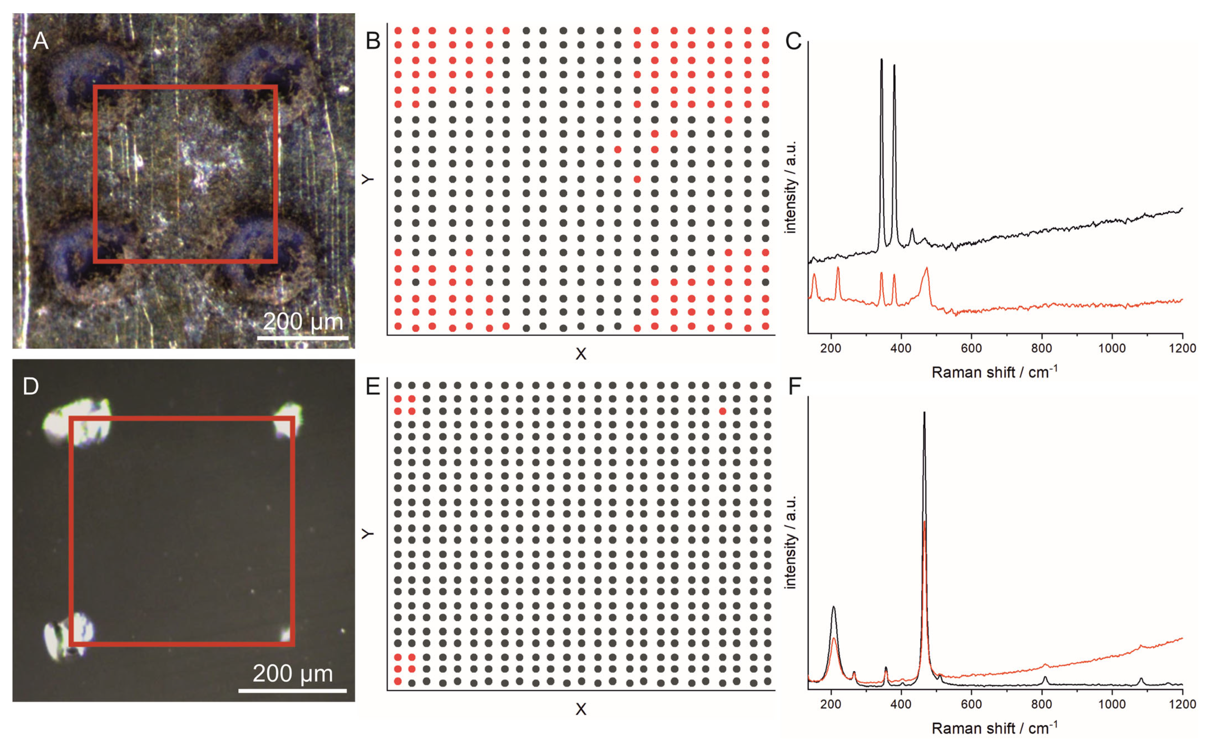
3.1. Influence of the LIBS Experiment on the Raman Measurements

To find out whether it is possible to obtain meaningful information in the Raman experiments after the rough LIBS scan, and if so, under which conditions, the influence of the LIBS experiment on the Raman information was investigated using four different minerals (barite, fahlore, pyrite and quartz). The minerals were chosen because of their different chemical compositions as well as their different physical properties, such as hardness, transparency and melting point. In Figure 2A–D, micrographs taken from the minerals after the LIBS experiment are displayed. It can be seen that the craters show very different sizes and morphologies, indicating different impacts of the laser in the LIBS experiment. Figure 2E–H show Raman spectra collected before and after the LIBS experiment on the same measurement spots where the LIBS experiment was performed. The spectra support the assumption of different impacts of the laser during the LIBS experiment. For some of the minerals (in this case, barite and fahlore (Figure 2E,F)), no or moderate changes were observed in the spectra, whereas for pyrite, significant differences could be observed in the spectra (Figure 2G). The changes observed in the spectra of pyrite are in agreement with previous observations [16] and could be assigned to the formation of elemental sulfur [32].
To investigate the spatial extent of the structural changes, Raman spectroscopy mappings were performed on quartz and pyrite in the area between four laser craters (indicated by the red square in Figure 3). The mapping results were analyzed using k-means clustering, where the spectra were grouped according to their similarity. For both minerals, the spectra were assigned to two groups. The mean spectra built from the spectra of the two groups are shown in Figure 3C for pyrite and in Figure 3F for quartz. In Figure 3B,E, k-means maps are displayed indicating where the spectra assigned to one group (indicated by the same color) were measured. From the k-means maps, we concluded that a distance of 400 µm used in the experiments is suitable to obtain unperturbed Raman spectra when the Raman measurements are performed in the area between the craters from the LIBS experiment.

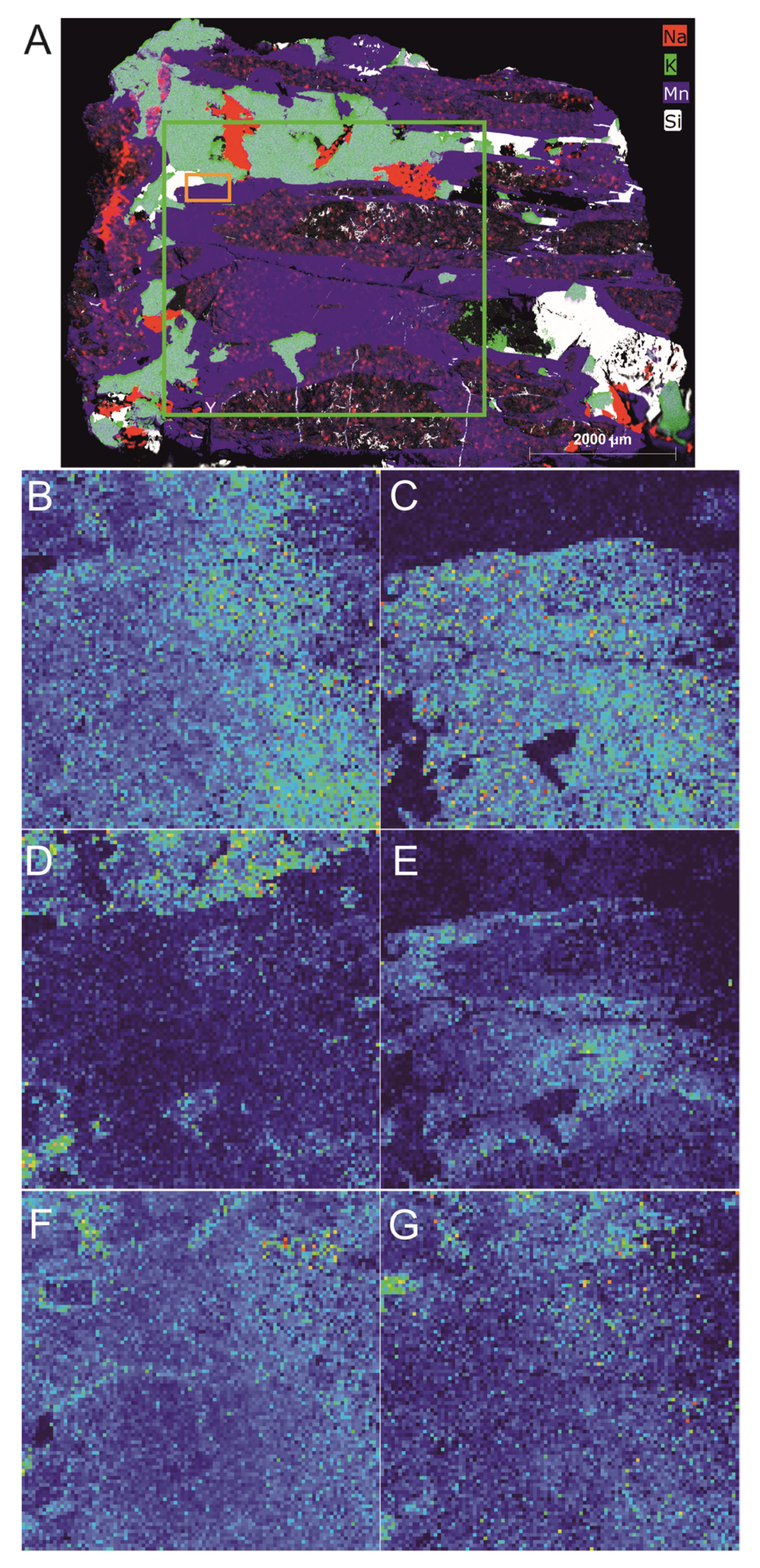
3.2. Results of the Analysis of the Fahlore Rock Sample with µ-EDXRF, LIBS and Raman Spectroscopy

The sample was analyzed according to the procedure shown in Figure 1. First, the whole sample was mapped with µ-EDXRF to obtain information on the element distribution with high spatial resolution and without altering the sample. The distribution of barium, copper, silicon and iron obtained from the µ-EDXRF measurements is shown in Figure 4A. Additionally, each pixel of the map was classified according to its similarity to previously defined mineral classes using a spectral angle mapper. This delivers the first indications of the distribution and partitioning of the different minerals in the sample (Figure 4B,C). Figure 4B shows the results of the classification. Each class is displayed with an individual color on the map. Afterwards, the sample was probed using LIBS with a step size of 400 µm. In Figure 4D,E, false color maps are displayed showing the distribution of barium, copper, iron and silicon. A comparison of the LIBS maps (Figure 4D,E) to the µ-EDXRF map (Figure 4A) shows that similar results were obtained for the two methods, emphasizing the potential of LIBS analysis for mineral analysis. Nevertheless, due to the distance of 400 µm between the measurement points in the LIBS experiment, small features (e.g., some of the small pyrite inclusions) are not detected in the rough LIBS scan. Furthermore, single Raman measurements were performed on the different mineral phases identified by the µ-EDXRF analysis. The spectra are shown in Figure 4F. The results fit well with the assignments obtained by the µ-EDXRF analyses. The bands found in the spectra can be assigned to barite (point 1), pyrite (point 2), quartz (point 3) and fahlore (point 4).
In the next step, a subsequent scan with Raman spectroscopy and LIBS with a step size of 20 µm was performed in a smaller region (indicated by the orange square in Figure 4A) to obtain further information on the mineral phases. The LIBS measurement was performed on the same measurement points as the Raman measurement to show that complementary information can be obtained. The Raman and LIBS spectra were analyzed using k-means clustering. In the k-means analysis, each spectrum is assigned to a group (cluster) based on the Euclidean distance between the spectra. The method showed itself to be feasible for the identification of areas in rocks with similar elemental compositions bases on LIBS spectra [10]. For the k-means analysis of the LIBS spectra, integral values of selected lines were used instead of the whole spectrum. The reason for this is that the number of lines is very different for different elements, and elements with many lines are weighted more strongly in the k-means analysis, which distorts it. The Raman spectra and LIBS line integral values were assigned to five groups (clusters) in the k-means analysis. The optimal number of clusters was determined using the PBM index [31], which is a measure for the intercluster–intracluster distance.
The results of the k-means analyses are displayed in Figure 5. Figure 5A,B show k-means maps showing which spectra are assigned to the same group (indicated by the same color) as a function of the measurement position. In Figure 5C,D, the mean of the Raman spectra and the standardized LIBS integral values belonging to one group can be seen. The group colors are the same as in Figure 5A,B. The mean Raman spectra for the five groups show bands that can be assigned to the minerals found in the single-point measurements (Figure 4F). The black spectrum shows bands that could be assigned to quartz, the light blue to fahlore, the green to pyrite and the blue to barite (Figure 5C). The red spectrum also shows bands that could be assigned to quartz, but an additional band at 144 cm−1 is visible (Figure 5C). This band can be assigned to anatase (titanium dioxide). This assignment is supported by the fact that titanium signals are found in the LIBS experiment in the regions where the Raman spectra showing the band at 144 cm−1 were measured (Figure 5B,D).
For the LIBS, individual groups are characterized by the elevated signal intensities of the following elements: silicon (black group); copper, silver and zinc (light-blue group); iron (green group); barium and strontium (dark-blue group); and silicon and titanium (red group). Additionally, the values for lines of other elements are slightly elevated. The reason is that the ablated volume is usually bigger than the focal spot size of the laser, and therefore—especially at the mineral boundaries—the signal does not come from a single mineral phase but from several mineral phases. Furthermore, when measuring with a small step size of 20 µm, the carryover of material can have an influence on the accuracy of the mapping because not all the ablated material is completely evaporated but is spread on the nearby sample surface. The impact of carryover depends on the properties of the mineral phases, but it should be low in most cases. The differences in the probed volume in the LIBS and Raman experiment also explain the small discrepancy in the k-means maps obtained from the two methods (Figure 5A,B). However, in general, it can be said that the results obtained with both methods match very well and, in some cases, complementary information can be obtained. For example, with LIBS, the elemental composition of the fahlore and the substitution of strontium in barite could be determined, which is not possible with Raman spectroscopy. Vice versa, it would not be possible to distinguish rutile from anatase (both titanium dioxide) based on elemental composition alone, but Raman spectroscopy is able to make an unambiguous assignment.

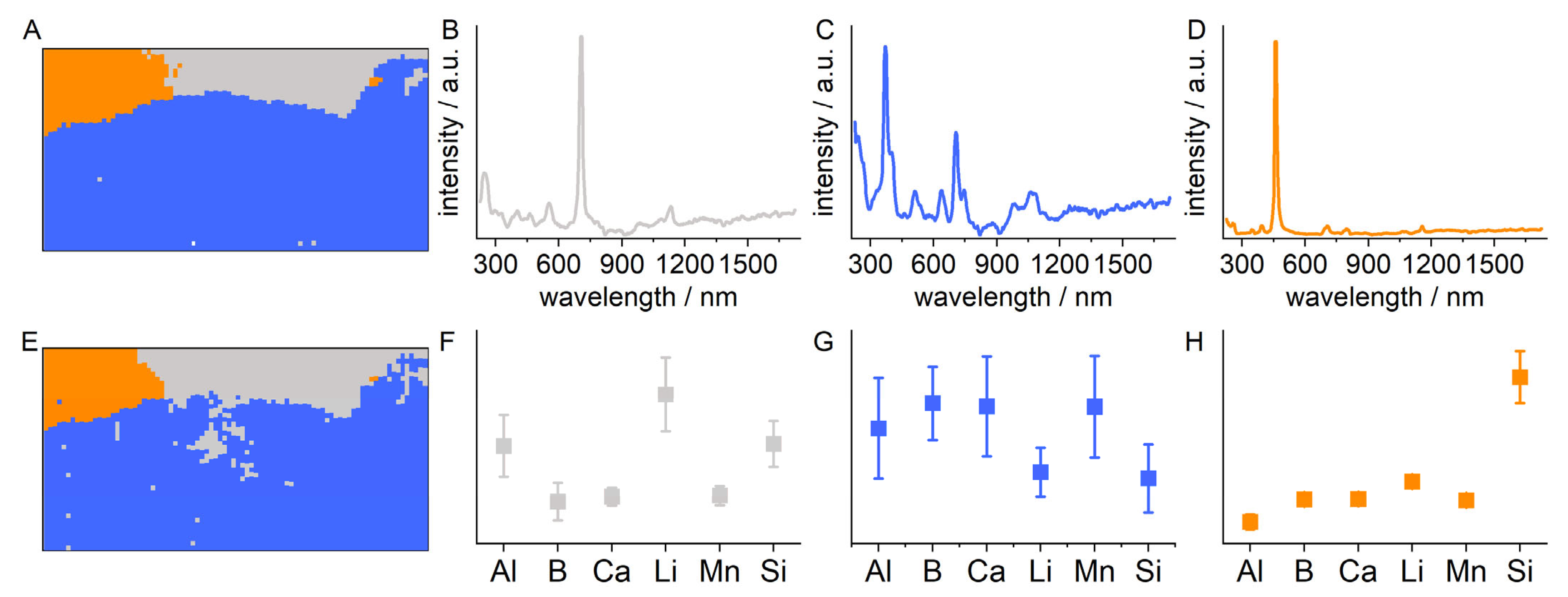
3.3. Results of the Analysis of the Tourmaline Rock Sample with µ-EDXRF, LIBS and Raman Spectroscopy

The workflow for the analysis was the same as for the fahlore sample. In the first step, a µ-EDXRF mapping of the whole sample was performed. Afterwards, the sample was roughly scanned by LIBS to obtain additional information on the distribution of light elements, such as boron and lithium. The results of the µ-EDXRF and rough LIBS scan are shown in Figure 6. The rough LIBS scan was conducted in the area marked by the green rectangle. The elemental maps obtained by both methods show similar distributions for manganese, silicon and sodium. Due to the much lower spatial resolution in the rough LIBS scan compared to the µ-EDXRF, small features are not detected with LIBS. With LIBS, additional information about the distribution of lithium and boron are obtained (Figure 6C,D). From these results, the first indications on the different mineral phases in the sample can be deduced. The maps from the two methods were used to define an ROI (marked with an orange rectangle in Figure 6A) for further investigation with LIBS and Raman spectroscopy.
The scan with Raman spectroscopy and LIBS in the ROI was performed with a step size of 20 µm. The LIBS measurement was performed on the same measurement points as the Raman measurement. The Raman and LIBS spectra were again analyzed using k-means clustering. The results are displayed in Figure 7. Calculating the PBM index indicated that three groups represent the variance in the obtained spectra best. Figure 7B–D show the mean Raman spectra for the three groups. The mean Raman spectra can be assigned to lepidolite, indicated by the signals at 250 cm−1, 555 cm−1, 707 cm−1 and 1134 cm−1 (grey spectrum, Figure 7B) [33,34], elbaite-type tourmaline, indicated by the signals at 637 cm−1 and 707 cm−1 (blue spectrum, Figure 7C) [35,36,37], and quartz, indicated by the signal at 460 cm−1 (orange spectrum, Figure 7D). The mean standardized integral values of selected LIBS lines for the three groups (Figure 7F–H) show elevated values for aluminum, lithium and silicon for the grey group, elevated values for aluminum, boron, calcium and manganese for the blue group and elevated values for silicon for the orange group. Figure 7A,B show the k-means maps indicating the positions where the spectra assigned to one group were measured. This allows the fine localization of the different mineral phases identified by the Raman spectra and the mean integral values of the selected LIBS lines. The k-means maps obtained from the LIBS and Raman spectra strongly resemble each other. The slight differences can again be explained by the different sample volumes that were probed by the different methods.

4. Conclusions

The results presented in this paper demonstrate that the combination of µ-EDXRF, LIBS and Raman spectroscopy delivers comprehensive information about mineral samples. The combination of LIBS and µ-EDXRF is useful because both methods have their drawbacks in the analysis of the elemental compositions of mineralogical samples. EDXRF can only hardly or not even detect light elements, while LIBS can change the mineral phases. With the combination of the methods in the described sequence, information on the elemental composition can be obtained for nearly all elements, leaving enough unchanged material for a subsequent analysis with Raman spectroscopy to obtain information about mineral phases and alterations. This is important both in mining and in studies of geological processes. Placing the measurement points for the Raman measurement into the center between the points of a fast LIBS screening is a good compromise between the measurement speed and correct mineral classification. Our results show that meaningful Raman spectra could be obtained if the point-to-point distance in the LIBS experiment is large enough (400 µm in this work).
The second high-resolution LIBS mapping in selected regions of interest gives a more detailed picture on the distribution of the light elements. k-means shows itself to be a feasible method to identify areas with similar elemental compositions and crystal structures from the LIBS and Raman spectroscopy data in large datasets. A future target is to estimate the lithium and boron contents within the individual phases, as these elements could be of diagnostic relevance for proxies of mineral deposits. Moreover, for this task, the proposed combination of methods could help. In LIBS, due to the matrix effect, different calibration models for different matrices (in this case different minerals) have to be used. This could be obtained from the combination of µ-EDXRF and Raman spectroscopy.

Author Contributions

V.M. performed the conceptualization, development of the methodology, curation of the LIBS and Raman data, analysis of the LIBS and Raman data and writing of the original draft. K.B. performed Raman measurements and analysis of the Raman data and participated in the writing of the original draft of the manuscript. D.R. performed the conceptualization, µ-EDXRF measurement and analysis of the µ-EDXRF data. L.P. performed the conceptualization, provided resources and reviewed the manuscript. All authors have read and agreed to the published version of the manuscript.

Funding

This research received no external funding.

Data Availability Statement

The data presented in this study are available on request from the corresponding author.

Acknowledgments

The authors would like to thank D. Schiller (LTB) for help with the design of the graphical abstract, and S. Merk (LTB) for proofreading.

Conflicts of Interest

The authors declare no conflict of interest.

References

  1. Nikonow, W.; Rammlmair, D. Automated mineralogy based on micro-energy-dispersive X-ray fluorescence microscopy (µ-EDXRF) applied to plutonic rock thin sections in comparison to a mineral liberation analyzer. Geosci. Instrum. Methods Data Syst. 2017, 6, 429–437. [Google Scholar] [CrossRef]
  2. Zhong, J.; Hu, C.-N.; Fan, H.-H.; Cai, Y.-Q.; Chen, Q.; Chen, J.-Y.; Meng, Y.-N. A new type U-Th-REE-Nb mineralization related to albitite: A case study from the Chachaxiangka deposit in the northeastern Qaidam Basin of China. China Geol. 2019, 2, 422–438. [Google Scholar] [CrossRef]
  3. Nikonow, W.; Rammlmair, D. Risk and benefit of diffraction in Energy Dispersive X-ray fluorescence mapping. Spectrochim. Acta B 2016, 125, 120–126. [Google Scholar] [CrossRef]
  4. Nikonow, W.; Rammlmair, D.; Meima, J.A.; Schodlok, M.C. Advanced mineral characterization and petrographic analysis by µ-EDXRF, LIBS, HSI and hyperspectral data merging. Mineral. Petrol. 2019, 113, 417–431. [Google Scholar] [CrossRef]
  5. Khajehzadeh, N.; Kauppinen, T.K. Fast mineral identification using elemental LIBS technique. IFAC-Pap. 2015, 48, 119–124. [Google Scholar] [CrossRef]
  6. Streubel, L.; Jacobsen, L.; Merk, S.; Thees, M.; Rammlmair, D.; Meima, J.; Mory, D. Rapid Analysis of Geological Drill-Cores with LIBS. Opt. Photonik 2016, 11, 23–27. [Google Scholar] [CrossRef]
  7. Harmon, R.S.; Lawley, C.J.M.; Watts, J.; Harraden, C.L.; Somers, A.M.; Hark, R.R. Laser-Induced Breakdown Spectroscopy—An Emerging Analytical Tool for Mineral Exploration. Minerals 2019, 9, 718. [Google Scholar] [CrossRef]
  8. Jolivet, L.; Leprince, M.; Moncayo, S.; Sorbier, L.; Lienemann, C.-P.; Motto-Ros, V. Review of the recent advances and applications of LIBS-based imaging. Spectrochim. Acta B 2019, 151, 41–53. [Google Scholar] [CrossRef]
  9. Fabre, C. Advances in Laser-Induced Breakdown Spectroscopy analysis for geology: A critical review. Spectrochim. Acta B 2020, 166, 105799. [Google Scholar] [CrossRef]
  10. Müller, S.; Meima, J.A.; Rammlmair, D. Detecting REE-rich areas in heterogeneous drill cores from Storkwitz using LIBS and a combination of k-means clustering and spatial raster analysis. J. Geochem. Explor. 2021, 221, 106697. [Google Scholar] [CrossRef]
  11. Meima, J.A.; Rammlmair, D.; Junge, M. The use of Laser Induced Breakdown Spectroscopy for the mineral chemistry of chromite, orthopyroxene and plagioclase from Merensky Reef and UG-2 chromitite, Bushveld Complex, South Africa. Chem. Geol. 2022, 589, 120686. [Google Scholar] [CrossRef]
  12. Velásquez, M.; Álvarez, J.; Sandoval, C.; Ramírez, E.; Bravo, M.; Fuentes, R.; Myakalwar, A.K.; Castillo, R.; Luarte, D.; Sbarbaro, D.; et al. Improved elemental quantification in copper ores by laser-induced breakdown spectroscopy with judicious data processing. Spectrochim. Acta B 2022, 188, 106343. [Google Scholar] [CrossRef]
  13. Ribeiro, R.; Capela, D.; Ferreira, M.; Martins, R.; Jorge, P.; Guimarães, D.; Lima, A. X-ray Fluorescence and Laser-Induced Breakdown Spectroscopy Analysis of Li-Rich Minerals in Veins from Argemela Tin Mine, Central Portugal. Minerals 2021, 11, 1169. [Google Scholar] [CrossRef]
  14. Müller, S.; Meima, J.A. Mineral classification of lithium-bearing pegmatites based on laser-induced breakdown spectroscopy: Application of semi-supervised learning to detect known minerals and unknown material. Spectrochim. Acta B 2022, 189, 106370. [Google Scholar] [CrossRef]
  15. Rifai, K.; Constantin, M.; Yilmaz, A.; Özcan, L.Ç.; Doucet, F.R.; Azami, N. Quantification of Lithium and Mineralogical Mapping in Crushed Ore Samples Using Laser Induced Breakdown Spectroscopy. Minerals 2022, 12, 253. [Google Scholar] [CrossRef]
  16. Fau, A.; Beyssac, O.; Gauthier, M.; Meslin, P.Y.; Cousin, A.; Benzerara, K.; Bernard, S.; Boulliard, J.C.; Gasnault, O.; Forni, O.; et al. Pulsed laser-induced heating of mineral phases: Implications for laser-induced breakdown spectroscopy combined with Raman spectroscopy. Spectrochim. Acta B 2019, 160, 105687. [Google Scholar] [CrossRef]
  17. Nasdala, L.; Smith, D.C.; Kaindl, R.; Ziemann, M.A. Raman spectroscopy: Analytical perspectives in mineralogical research. In Spectroscopic Methods in Mineralogy; Beran, A., Libowitzky, E., Eds.; Mineralogical Society of Great Britain and Ireland: London, UK, 2004. [Google Scholar]
  18. Chang, H.; Huang, P.J. Thermo-Raman studies on anatase and rutile. J. Raman Spec. 1998, 29, 97–102. [Google Scholar] [CrossRef]
  19. Frost, R.L.; Bahfenne, S.; Graham, J. Raman spectroscopic study of the magnesium-carbonate minerals—Artinite and dypingite. J. Raman Spec. 2009, 40, 855–860. [Google Scholar] [CrossRef]
  20. Parker, J.E.; Thompson, S.P.; Lennie, A.R.; Potter, J.; Tang, C.C. A study of the aragonite-calcite transformation using Raman spectroscopy, synchrotron powder diffraction and scanning electron microscopy. CrystEngComm 2010, 12, 1590–1599. [Google Scholar] [CrossRef]
  21. Środek, D.; Dulski, M.; Galuskina, I. Raman imaging as a new approach to identification of the mayenite group minerals. Sci. Rep. 2018, 8, 13593. [Google Scholar] [CrossRef] [PubMed]
  22. Foucher, F.; Guimbretière, G.; Bost, N.; Westall, F. Petrographical and Mineralogical Applications of Raman Mapping. In Raman Spectroscopy and Applications; Maaz, K., Ed.; Intech: London, UK, 2017; pp. 163–180. [Google Scholar]
  23. Frezzotti, M.L.; Tecce, F.; Casagli, A. Raman spectroscopy for fluid inclusion analysis. J. Geochem. Explor. 2012, 112, 1–20. [Google Scholar] [CrossRef]
  24. Thomas, R.; Davidson, P. The application of Raman spectroscopy in the study of fluid and melt inclusions. Z. Dtsch. Ges. Geowiss. 2012, 163, 113–126. [Google Scholar] [CrossRef]
  25. Choi, S.; Kim, D.; Yang, J.; Yoh, J.J. Accuracy Enhancement of Raman Spectroscopy Using Complementary Laser-Induced Breakdown Spectroscopy (LIBS) with Geologically Mixed Samples. Appl. Spectrosc. 2017, 71, 678–685. [Google Scholar] [CrossRef]
  26. Rammelkamp, K.; Schröder, S.; Kubitza, S.; Vogt, D.S.; Frohmann, S.; Hansen, P.B.; Böttger, U.; Hanke, F.; Hübers, H.-W. Low-level LIBS and Raman data fusion in the context of in situ Mars exploration. J. Raman Spec. 2019, 51, 1682–1701. [Google Scholar] [CrossRef]
  27. Huamán, J.L.C.; Tadini, A.M.; Senesi, G.S.; Mounier, S.; Milori, D.M.B.P.; Nicolodelli, G. Characterization of an Amazon Soil Profile by Laser-Induced Breakdown, Raman, and Fluorescence Spectroscopies. Minerals 2023, 13, 553. [Google Scholar] [CrossRef]
  28. Kruse, F.A.; Lefkoff, A.B.; Boardman, J.W.; Heidebrecht, K.B.; Shapiro, A.T.; Barloon, P.J.; Goetz, A.F.H. The spectral image processing system (SIPS)—Interactive visualization and analysis of imaging spectrometer data. Remote Sens. Environ. 1993, 44, 145–163. [Google Scholar] [CrossRef]
  29. Baek, S.-J.; Park, A.; Ahn, Y.-J.; Choo, J. Baseline correction using asymmetrically reweighted penalized least squares smoothing. Analyst 2015, 140, 250–257. [Google Scholar] [CrossRef]
  30. Arthur, D.; Vassilvitskii, S. K-means++: The Advantages of Careful Seeding. In Proceedings of the Eighteenth Annual ACM-SIAM Symposium on Discrete Algorithms, New Orleans, LA, USA, 7–9 June 2007. [Google Scholar]
  31. Pakhira, M.K.; Dutta, A. Computing approximate value of the pbm index for counting number of clusters using genetic algorithm. In Proceedings of the International Conference on Recent Trends in Information Systems (ReTIS), Kolkata, India, 21–23 December 2011. [Google Scholar]
  32. Trofimov, B.A.; Sinegovskaya, L.M.; Gusarova, N.K. Vibrations of the S-S bond in elemental sulfur and organic polysulfides: A structural guide. J. Sulfur Chem. 2009, 30, 518–554. [Google Scholar] [CrossRef]
  33. Robert, J.-L.; Beny, J.-M.; Beny, C.; Volfinger, M. Characterization of lepidolites by Raman and infrared spectrometries; I, Relationships between OH-stretching wavenumbers and composition. Can. Mineral. 1989, 27, 225–235. [Google Scholar]
  34. Wang, A.; Freeman, J.J.; Jolliff, B.L. Understanding the Raman spectral features of phyllosilicates. J. Raman Spec. 2015, 46, 829–845. [Google Scholar] [CrossRef]
  35. Gasharova, B.; Mihailova, B.; Konstantinov, L. Raman spectra of various types of tourmaline. Eur. J. Mineral. 1997, 9, 935–940. [Google Scholar] [CrossRef]
  36. Hoang, L.H.; Hien, N.T.M.; Chen, X.B.; Minh, N.V.; Yang, I.-S. Raman spectroscopic study of various types of tourmalines. J. Raman Spec. 2011, 42, 1442–1446. [Google Scholar] [CrossRef]
  37. Bosi, F.; Celata, B.; Skogby, H.; Hålenius, U.; Tempesta, G.; Ciriotti, M.E.; Bittarello, E.; Marengo, A. Mn-bearing purplish-red tourmaline from the Anjanabonoina pegmatite, Madagascar. Mineral. Mag. 2021, 85, 242–253. [Google Scholar] [CrossRef]
Figure 1. Strategy for the analysis of mineralogical samples with a combination of µ-EDXRF, LIBS and Raman spectroscopy.
Minerals 13 00729 g001
Figure 2. (AD) Micrographs of four different minerals after the LIBS experiment (3 mJ, 1 pulse); (EH) Raman spectra before (black) and after (red) the LIBS experiment (λ = 532 nm, I = 6.4 × 10⁵ W·cm−2). (A,E) Barite; (B,F) fahlore; (C,G) pyrite; (D,H) quartz.
Minerals 13 00729 g002
Figure 3. Results of Raman spectroscopy mappings after LIBS experiment on (AC) pyrite and (DF) quartz. (A,D) Micrographs after a LIBS experiment. The red squares indicate the areas in which the Raman mappings were performed. (B,E) k-means maps showing the group number (indicated by different colors), resulting from the k-means analysis of the Raman spectra, as function of the measurement position. (C,F) Mean Raman spectra of the spectra corresponding to one group (group number is indicated by the color). The Raman measurements were performed with a distance between the sampling points of 10 µm (λ = 532 nm, I = 6.4 × 10⁵ W·cm−2, integration time: 500 ms).
Minerals 13 00729 g003
Figure 4. Results of the mapping of the whole fahlore sample with µ-EDXRF and LIBS and the single-point analysis with Raman spectroscopy. (A) µ-EDXRF and (D,E) LIBS mapping showing the element distribution of barium, copper, iron and silicon in false color. The orange rectangle in (A) shows the area in which the fine Raman–LIBS scan was performed. (B) Spectral angle mapper (SAM)-based supervised mineral classification with (C) mineral partitioning as a result of the µ-EDXRF mapping. (F) Raman spectra obtained by single measurements on the points marked in black in image (A). The Raman spectra can be assigned to the following mineral phases: (1) barite; (2) pyrite; (3) quartz; (4) fahlore.
Minerals 13 00729 g004
Figure 5. Results of the k-means analysis of the LIBS–Raman mapping with high spatial resolution (step size: 20 µm). (A,B) k-means maps showing which spectra are assigned to the same group (indicated by the same color) as a function of the measurement position for the (A) Raman spectra and (B) LIBS spectra. (C) Mean spectra of the Raman spectra and (D) means of the standardized LIBS integral values belonging to one group (group colors are the same as in (A,B): black: quartz; light blue: fahlore; green: pyrite; blue: barite; red: quartz with anatase.
Minerals 13 00729 g005
Figure 6. (A) Results of the mapping of the whole tourmaline sample with µ-EDXRF and (BG) the rough LIBS scan. For convenience, only the results for some selected elements are shown ((A) manganese, potassium, silicon and sodium for µ-EDXRF and (B) aluminum, (C) boron, (D) lithium, (E) manganese, (F) sodium and (G) silicon for LIBS). The rough LIBS scan was performed in an area of 40 × 40 mm (roughly marked by the green rectangle in (A)). The orange rectangle in (A) marks the area in which the fine Raman–LIBS scan was performed.
Minerals 13 00729 g006
Figure 7. Results of the k-means analysis of the LIBS–Raman mapping with high spatial resolution (distance between measurement points: 20 µm). (A,E) k-means maps showing which spectra are assigned to the same group (indicated by the same color) as function of the measurement position for the (A) Raman spectra and (E) LIBS spectra. (BD) Mean spectra of the Raman spectra and (FH) means of the standardized LIBS integral values belonging to one group (group colors are the same as in (A,E): grey: lepidolite; blue: elbaite-type tourmaline; and orange: quartz). LIBS integral values are shown for the following lines: aluminum: 308.22 nm; boron: 249.68 nm; calcium: 393.37 nm; lithium: 610.37 nm; manganese: 257.61 nm; and silicon: 390.56 nm.
Minerals 13 00729 g007
Table 1. Center wavelengths of the LIBS lines used for the k-means analysis.
ElementCenter Wavelength(s) of Selected Lines/nm
Aluminum (Al)308.22396.16
Antimony (Sb)206.83277.00
Arsenic (As)234.99278.04
Barium (Ba)553.55614.20
Boron (B)249.68249.78
Cadmium (Cd)214.44226.51
Calcium (Ca)393.37 396.83
Copper (Cu)282.44578.21
Iron (Fe)372.00373.49
Lithium (Li)610.37/
Manganese (Mn)257.61259.37
Silicon (Si)288.17390.56
Silver (Ag)328.07338.29
Strontium (Sr)407.78421.56
Titanium (Ti)336.12337.26
Zinc (Zn)206.19330.25
Disclaimer/Publisher’s Note: The statements, opinions and data contained in all publications are solely those of the individual author(s) and contributor(s) and not of MDPI and/or the editor(s). MDPI and/or the editor(s) disclaim responsibility for any injury to people or property resulting from any ideas, methods, instructions or products referred to in the content.

