Article

The Unconventional Peridotite-Related Mg-Fe-B Skarn of the El Robledal, SE Spain

by
Igor González-Pérez
1,*,
Isabel Fanlo
2,
Gonzalo Ares
3,
Fernando Gervilla
1,4,
José María González-Jiménez
4,
Antonio Acosta-Vigil
4 and
Enrique Arranz
2
1
Departamento de Mineralogía y Petrología, Facultad de Ciencias, Universidad de Granada, Avda. Fuentenueva s/n, 18002 Granada, Spain
2
Departamento de Ciencias de la Tierra, Cristalografía y Mineralogía, Universidad de Zaragoza, Pedro Cerbuna 12, 50009 Zaragoza, Spain
3
Instituto de Geociencias (IGEO, CSIC-UCM), c/Severo Ochoa, 7, 28040 Madrid, Spain
4
Instituto Andaluz de Ciencias de la Tierra (IACT), CSIC-UGR, Avda. de las Palmeras 4, 18100 Armilla, Spain
*
Author to whom correspondence should be addressed.
Minerals 2023, 13(3), 300; https://doi.org/10.3390/min13030300
Submission received: 11 January 2023 / Revised: 30 January 2023 / Accepted: 1 February 2023 / Published: 21 February 2023
(This article belongs to the Section Mineral Deposits)

Abstract

:
The El Robledal deposit is a Mg-Fe-B skarn hosted in a dismembered block from the footwall contact of the Ronda orogenic peridotites in the westernmost part of the Betic Cordillera. The skarn is subdivided into two different zones according to the dominant ore mineral assemblage: (1) the ludwigite–magnetite zone, hosted in a completely mineralized body along with metasomatic forsterite, and (2) the magnetite–szaibelyite zone hosted in dolomitic marbles. In the ludwigite–magnetite zone, the massive mineralization comprises ludwigite (Mg2Fe3+(BO3)O2), Mg-rich magnetite, and magnetite, with minor amounts of kotoite (Mg3(BO3)2), szaibelyite (MgBO2(OH)), accessory schoenfliesite (MgSn4+(OH)6), and pentlandite. The ratio of ludwigite–magnetite decreases downwards in the stratigraphy of this zone. In contrast, the mineralization in the magnetite–szaibelyite zone is mainly composed of irregular and folded magnetite pods and bands with pull-apart fractures, locally associated with a brucite-, szaibelyite-, and serpentine-rich groundmass. The set of inclusions identified within these ore minerals, using a combination of a focused ion beam (FIB) and high-resolution transmission electron microscope (HRTEM), supports the proposed evolution of the system and reactions of the mineral formation of the skarn. The analysis of the microstructures of the ores by means of electron backscatter diffraction (EBSD) allowed for the determination that the ores experienced ductile deformation followed by variable degrees of recrystallization and annealing. We propose a new classification of the deposit as well as a plausible genetic model in a deposit where the heat source and the ore-fluid source are decoupled.

1. Introduction

To date, over 250 boron-bearing minerals have been identified, which may be divided into three broad groups according to their origin and geological environments: (1) Mg-bearing borates intimately associated with silicates and iron oxides in magnesian skarn (hereafter Mg-skarn) typically related to intermediate calk-alkaline intrusive igneous rocks; (2) Mg-bearing oxides, hosted by marine evaporitic sediments; and (3) Na- and Ca-bearing borate hydrates associated with lacustrine (playa lake) sediments and explosive volcanic activity [1]. Mg-skarn deposits hosting boron mineralizations are spread worldwide [2,3,4], and they are of particular interest, as they are an economically reliable source not only for B but also for Fe and Sn [3]. A common feature of all of these types of deposits is their characteristic mineralogical zoning due to the fact of fluid-related metasomatism at varying fluid and/or melt/rock ratios and temperatures [5]. B-bearing Mg-skarns are usually characterized by the occurrence of mineralogical zoning that from the intrusion outwards are represented by (1) proximal magnesian silicates (e.g., diopside, forsterite, and spinel), (2) magnetite and magnesian borates ores, and (3) periclase or monticellite marble in direct contact with Mg-rich carbonate protolith [6]. These mineral assemblages are accompanied by their resulting altered minerals (i.e., humite, chondrodite, serpentine, phlogopite, calcite, and brucite). Thus, endogenous borates in Mg-skarn deposits are systematically developed on the outermost part of the contact aureole formed at the contact between igneous rocks and dolomite protolith [2,6,7,8,9,10,11,12,13,14].
Broadly speaking, B-bearing Mg-skarns are classified into four broad categories based on the prevailing borate mineralogy [14]: (1) type (Mg-B) is Fe-poor, containing basically kotoite (Mg3(BO3)2), suanite Mg2((B2O5)), and szaibelyite (Mg2BO2(OH)); (2) type (Mg-Fe-B) is Fe-rich, with ludwigite (Mg2Fe3+(BO3)O2) associated with magnetite; (3) type (Mg-Ca-B-CO2) includes carbonate-bearing Ca-Mg borates; and (4) type (Mg-Ca-B) is rare and contains kurchatovite or clinokurchatovite (Ca(Mg, Mn, Fe2+)B2O5) and develops at high pressures.
In this paper, we report the first detailed mineralogical characterization of the borate mineralization from the El Robledal Mg-Fe-B-skarn deposit in SW Spain. The singularity of this deposit is that it is hosted in dolomitic marbles of the contact aureole produced by the crustal emplacement of the Ronda Peridotites, the largest outcrops of Subcontinental Lithospheric Mantle peridotites exposed on the Earth’s surface ([15] and references therein). This is a very uncommon geological framework for the formation of a Mg-Fe-B-skarn deposit, where the source of heat (i.e., Ronda Peridotites) and fluid (migmatites) are apparently decoupled, unlike conventional Mg-Fe-B-skarn deposits, where heat and fluids come from intrusive igneous rocks. This offers an opportunity to better constrain the physicochemical conditions of this type of mineral deposit. We sought to unravel the potential role played by country rocks (i.e., Ronda Peridotites, migmatites, and related leucogranites) for the generation of mineralizing fluids responsible for the formation of the skarn. To achieve these targets, we provide and discuss the micro-analytical data obtained using a combination of techniques including (1) high-resolution scanning electron microscopy (HRSEM), (2) an electron probe micro-analyzer (EPMA), (3) electron back-scattered diffraction (EBSD), and (4) a focused ion beam (FIB) combined with high-resolution transmission electron microscopy (HRTEM). These data were integrated into an innovative model that links the genesis of this B-rich skarn deposit to fluids released from the anatexis and dehydration of metasediments during the hot emplacement of the mantle peridotites into the continental crust.

2. Geological Setting

The El Robledal deposit is located in the southwestern area of the Sierra de Las Nieves, in the western part of the Betic Cordillera, southern Spain, ~22 km northwestwards from the city of Marbella (Figure 1). The Betic Cordillera along with the Rif in north Morocco constitute an arched alpine orogenic belt formed during the N–S to NW–SE convergence of the Eurasian and African plates along with the westward migration of the Alborán domain [16,17,18,19]. Three different domains comprise the geology of the Betic Cordillera: External Domain, Internal Domain, and Flysch (Figure 1 inset). The External Domain is in the north of the belt and corresponds to Mesozoic to Cenozoic sedimentary rocks. The Internal Domain exposes three stacked tectonic complexes that from bottom to top are the Nevado-Filábride Complex, the Alpujárride Complex, and the Maláguide Complex. They consist of a variable degree of metamorphized Paleozoic to Mesozoic sediments deposited between the Iberia and Africa plates. The Flysch domain is sandwiched between the aforementioned domains, representing Cretaceous to Miocene turbiditic sediments [20]. The Alpujárride complex in its westernmost part comprises two main units: Los Reales Unit and Blanca Unit. The Los Reales Unit is the uppermost unit including in its lower portion a ca. 4 km thick slice of a subcontinental lithospheric mantle (SCLM)—the Ronda Peridotites—and an overlying <5 km thick crustal sequence (Balanyá et al. [21], identified as the Jubrique group).
The Ronda Peridotites are the larger known exposure (~450 km2) of the SCLM peridotites on Earth [22]. Altogether they are portions of a Proterozoic SCLM (1.2–1.8 Ga) now cropping out in three main ultramafic massifs: Ronda (~300 km2), Ojén (~70 km2), and Carratraca (~60 km2) [23,24,25,26]. These peridotites are sandwiched between crustal sequences (i.e., Jubrique group at the top and Blanca Unit at the bottom), which show an increasing metamorphic grade towards the mantle rocks, forming mylonitic bands at the contacts [27]. Large blocks from the top of the Blanca Unit are commonly embedded in the mylonitic band at the contact with the Ronda Peridotites [28]. The El Robledal deposit is hosted by one of these blocks, similar to other skarn-related deposits widespread along the Ronda Peridotites–Blanca Unit contact [29,30].
The rocks from the crustal sequence of the Jubrique group range from garnet-bearing granulitic gneisses (i.e., kinzigites; 12–14 kbar and 850 °C) in contact with the Ronda Peridotites to metapelites, marbles and low-grade phyllites (7–8 kbar and 200–350 °C) at the top of the sequence [31,32,33]. These rocks represent the pre-Mesozoic continental crust that was extremely thinned during Alpine Orogeny ([19] and references therein), although some authors suggested that there was a previous event of orogenic accretion during the Hercynian [34,35,36].
The Blanca Unit is composed of high-grade metapelites and migmatites underlying a Middle to Upper Triassic carbonate-rich metasedimentary sequence [37,38]. This unit includes several low-pressure and medium- to coarse-grained diatexites and metatexites (equilibrated at 3–5 kbar and 700–750 °C) [31,39,40]. These rocks are interpreted as the product of the anatexis of former metapelitic rocks during the high-temperature thrust emplacement of the Ronda Peridotites over these crustal rocks [27,28,37,41,42].
Leucogranitic dikes emanating from the migmatites crosscut the peridotite slab and the crustal rocks of the Blanca Unit along steep-dipping open joints that mostly trend NW–SE [43,44]. These dykes show cm to m thicknesses and crystallized at low pressure (<4 kbar) and high temperatures (>750 °C) [33,37,45,46]. Previous geochronological Rb–Sr (22 ± 4 Ma) [47] and, particularly U–Pb sensitive high-resolution ion microprobe (SHRIMP) and laser ablation inductively coupled plasma mass spectrometry (LA–ICP-MS) studies (18.8 ± 4.9 Ma) [38]; (22.3 ± 0.2 Ma) [48]; (21.5 ± 3.8 and 22.6 ± 1.8 Ma) [49], determined that the dikes crystallized during the 19–22 Ma timespan. Moreover, González-Jímenez et al. [50] dated magmatic zircons in plagioclasite and chromitite from the Ojén Massif that also yielded ~18–21 Ma. These data support the Alpine intracrustal emplacement of peridotites and suggest a genetic link between mineralizations and anatectic melts that originated during such emplacement. Nevertheless, Acosta-Vigil et al. [33] have found in migmatites from the Blanca unit zircons with magmatic overgrowths of ~280–290 Ma a later thermal and fluid overprint ca. 30 Ma, suggesting that Alpine anatexis is only limited to the very contact with the peridotites—see also [33,34,43].

3. Materials and Methods

A selected set of 30 samples was employed in this study to perform polished thin sections to characterize the mineralogy of the targeted skarn deposit. These thin sections were first inspected by conventional petrographic microscopy under both transmitted and reflected light to identify rock fabrics and textural relationships between transparent and opaque minerals. This task was achieved using an OLYMPUS-BX microscope at the Department of Mineralogy and Petrology at the University of Granada. The preliminary chemical identification and microphotographs of the minerals were acquired by electron microscopy using a Carl Zeiss MERLIN Field Emission Scanning Electron Microscope (FE-SEM) by applying the back-scattered electron (BSE) mode at the Universidad de Zaragoza. The accelerating voltage was 20 kV, the beam current was 10 nA, and the working distance was 15 mm.
The EBSD measurements on the selected areas of the analyzed samples were carried out using a Carl Zeiss MERLIN FE-SEM at the Universidad de Zaragoza. It was equipped with an HKL detector operated at an acceleration voltage of 20 kV (beam current: ~10 nA) and with a tiltable XY stage, including a rotation function around the stage normal z. The samples were tilted 70° relative to the incident beam at 18.5 mm from the pole piece, and at each position, an electron backscatter pattern (EBSP) was collected and stored. The signal was corrected in a postprocessing step using Phi-rho-Z, which showed a better correlation to stoichiometry than ZAF. The dwell time was 15 ms per point (average of 2 EBSD frames). The magnification was 750×, with a working distance of 18.5 mm and a step width of 0.5 µm.
The quantification of the major element compositions in the minerals was carried out using a JEOL JXA-8230 electron probe microanalyzer at the Serveis Científics i Tècnics of the Universitat de Barcelona, which has a specific crystal (LDE2) for light elements. The analytical conditions were a 15 kV accelerating voltage, 15 to 30 nA focused electron beam current, 5 μm spot diameter, and counting times of 30 s for boron, 10 s for the rest of the elements on peaks, and 15 and 5 s on the backgrounds, respectively. The ZAF corrections were performed using the program supplied by JEOL. Diopside (Si), corundum (Al), periclase (Mg), hematite (Fe), wollastonite (Ca), vonsenite (B), fluorite (F), rutile (Ti), and cassiterite (Sn) were used as reference materials for the calibration. The atoms per formula (apfu) were calculated assuming the ideal stoichiometry of the borate minerals (4 apfu for the ludwigite group minerals and 2 apfu for szaibelyite). Supplementary Material includes all the EPMA analyses of the skarn minerals.
Several regions of the samples were selected for mapping. For each map, several orientation-contrast mapping methods were applied to identify the distinctively different characteristics of the microstructures within phases, such as band contrast (BC), band slope (BS), and pattern quality (PQ) maps. These revealed deformed regions, grain boundaries, strain, and distinguished between crystallographically similar phases but different in defect content. The IPF (inverse pole figure) maps and pole figures show crystallographic orientations in the X-, Y-, or Z-direction, producing a different color for each orientation according to the crystallographic axis. The overall percentage of indexing in the maps was between 80% and 85%, and most of the no-index points corresponded to small holes and cracks. To estimate the pattern indexing reliability, we used the mean angular deviation (MAD), which describes the average angular difference between the position of Kikuchi bands in both the simulated and the acquired pattern. It is expressed as an angle in degrees. All calculations and simulations used to calculate these two parameters were acquired using the Flamenco software, which is used for pattern acquisition in the Channel 5 system. Indexation is possible with a MAD value smaller than 1°.
Three thin-foil samples (two from the ludwigite–magnetite zone and another one from the magnetite–szaibelyite zone) were prepared and extracted from Mg-rich magnetite grains using a focused ion beam scanning electron microscope (FIB-SEM) in the Laboratorio de Microscopías Avanzadas (LMA) at the Instituto de Nanociencia de Aragón (INA)—University of Zaragoza, Spain. The thin foil preparation was performed using a Dual Beam FEI Thermo-Fisher Scientific, model Helios 650. The selected regions of interest were first covered by a thin strip (~300 nm) of C via focused electron beam-induced deposition (FEBID) and, subsequently with a second strip (~1 µm) of Pt. The bulk material was first removed on both sides of the lamella by a rough Ga+ ion milling with a 30 kV current at 2.5 nA and the subsequent polishing with a 30 kV current at 0.23 nA. Electron transparency was reached by the final polishing and subsequent milling of the thin foil with a 5 kV current at 68 pA. The electron transparency was monitored by an Everhart-Thornley SE detector and using a 5 kV electron beam. After achieving the electron transparency, the thin foil was rapidly polished using a low energy 5 kV current at 10 pA to reduce the amorphization until a final thin foil thickness of ~90 nm was attained. Subsequently, the thin foil was undercut with a 30 kV at 2.5 nA current, lifted out and transferred from the sample to a TEM grid using an OmniProbe nanomanipulator with a tungsten tip.
A ThermoFisher FEI Titan G2 transmission electron microscope (TEM) equipped with a field emission gun XFEG was used to analyze the thin foil at the Centro de Instrumentation Científica of the University of Granada, Spain. The FEI Titan G2 microscope was equipped with 4 energy-dispersive analyses of X-ray (EDX) detectors (FEI microanalysis Super X), a high-angle annular dark-field detector (HAADF), as well as spherical correction for the objective lens (Eindhoven, Netherlands).
The selected mineral areas of interest were imaged using the combination of HAADF to obtain Z high contrast images, and HRTEM images to characterize the texture and the ordering of the mineral aggregates. All these images were treated using the Digital Micrograph®® software in its Version 1.71.38 developed by Gatan, while the maps were processed with the VELOX®® software package developed by ThermoFisher. The FEI Titan G2 was operated at 300 kV working conditions, while the HRTEM images were acquired using a Gatan CCD camera (Pleasanton, CA, USA). The compositional elemental mappings of the samples were obtained using 200 kV of accelerating voltage and image drift correction.

4. Results

4.1. The El Robledal Deposit

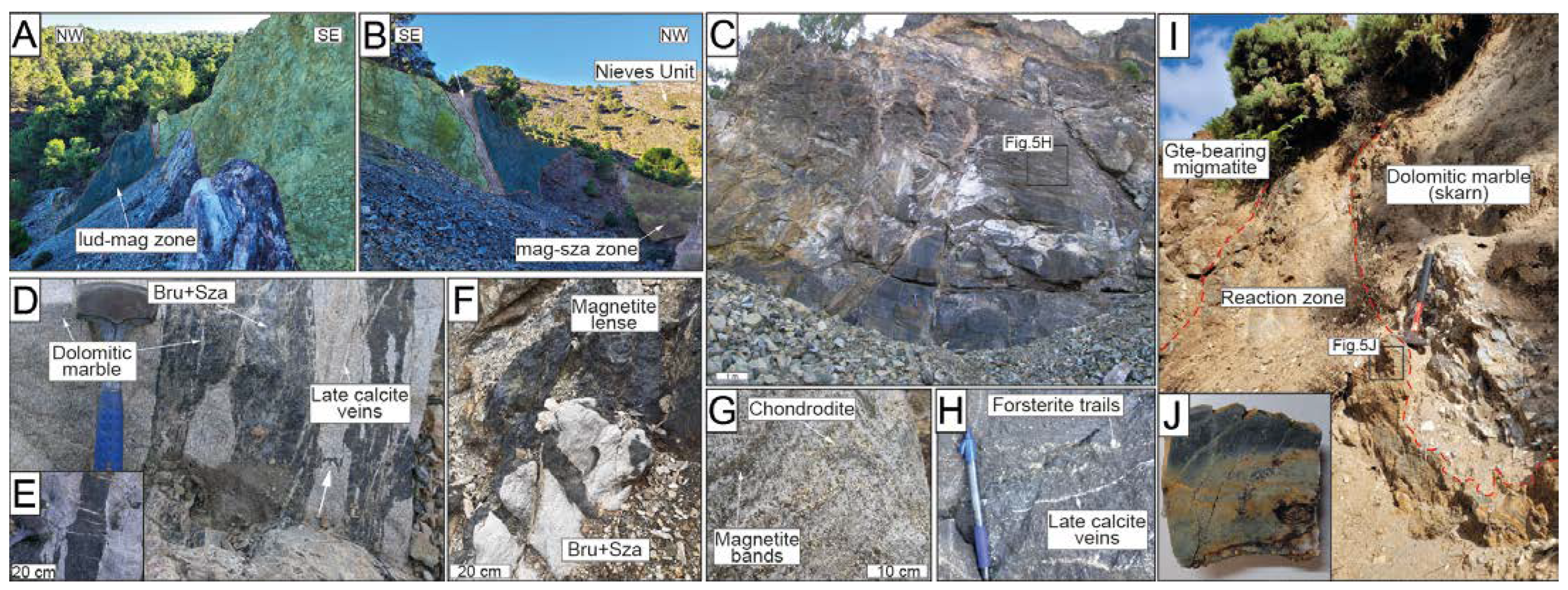
The El Robledal deposit is hosted in a dismembered block of the Blanca Unit, including dolomitic marble overlying migmatites. The block is embedded in the mylonitic band of the contact aureole surrounding the Ronda Peridotites and crops out at the southern part of Sierra de Las Nieves, along the contact between the Ronda Peridotites and the partly metamorphosed carbonates of the Las Nieves Unit (Figure 2). The outcrop is now an open-pit mine trench that exposes remnants of the mineralized body over 70–80 m in the E–W direction with a thickness of 25 m at a depth of 10–15 m. The mineralized body is mainly composed of magnetite and borates with two contrasting zones: (1) structurally upper mineralized body, representing the ludwigite–magnetite zone ca. 9 × 12 × 4 m in contact with highly serpentinized peridotites (i.e., the Ronda Peridotites) to the south, clamped between two strike-slip faults trending N60–80°, limiting the mineralization; (2) structurally lower mineralized dolomitic marble body representing the magnetite–szaibelyite zone in contact with the underlying cordierite- and garnet-bearing migmatites to the north (Figure 2C). The contact between the dolomitic marbles from the skarn and the underlying migmatites is defined by a reaction zone (i.e., black wall) ca. 30 cm thick of green-colored amphibolite exhibiting sharp contacts with the host rocks (Figure 3I,J).

4.2. Mineralogy of the Skarn Zones

The mineralization of the El Robledal deposit consists of ludwigite, Mg-rich magnetite, magnetite, and szaibelyite, with minor kotoite and schoenfliesite (MgSn4+(OH)6). However, their distribution is nonhomogeneous and exhibits marked mineralogical and textural variations depending on the skarn zone.

4.2.1. Ludwigite–Magnetite Zone

The mineral assemblage in this zone includes ludwigite, Mg-rich magnetite, magnetite, forsterite, two types of brucite (i.e., brucite-I and brucite-II), chondrodite, and variable proportions of double-layered hydroxides belonging to the hydrotalcite supergroup (hydrotalcite (Mg6Al2CO3(OH)16·4H2O), pyroaurite (Mg6Fe3+2(OH)16(CO3)·4H2O), and coalingite (Mg10Fe3+2(OH)24(CO3)·2H2O)), hydrous borates (szaibelyite and scarce wightmanite (Mg5(BO3)O(OH)5·2H2O)), kotoite, periclase, schoenfliesite, hydrous Mg-carbonates (i.e., hydromagnesite (Mg5(CO3)4(OH)2·4H2O)), serpentine, and calcite. The latter crosscuts the whole ludwigite–magnetite zone. Forsterite commonly forms trails of partially serpentinized, euhedral to subhedral grains (<2 mm across) embedded within the ludwigite and magnetite groundmass (Figure 3H).
This zone is dominated by massive ludwigite, Mg-rich magnetite, and magnetite the proportion of which within the orebody varies according to their distance to the tectonic contact with the Ronda Peridotites. Thus, ludwigite is the most abundant mineral close to the peridotites, whereas Mg-rich magnetite and magnetite abundances increase gradually in the magnetite–szaibelyite zone.
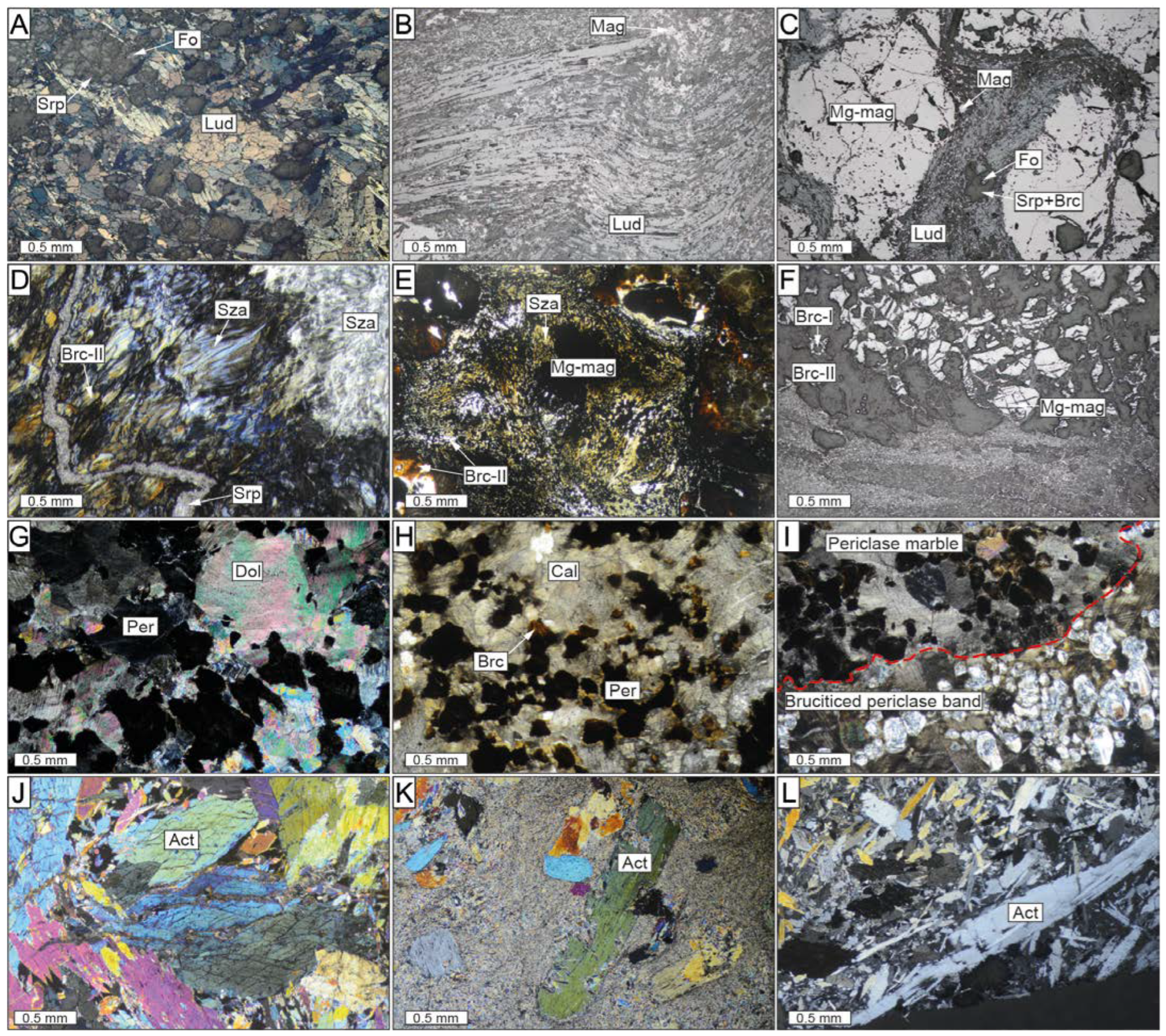
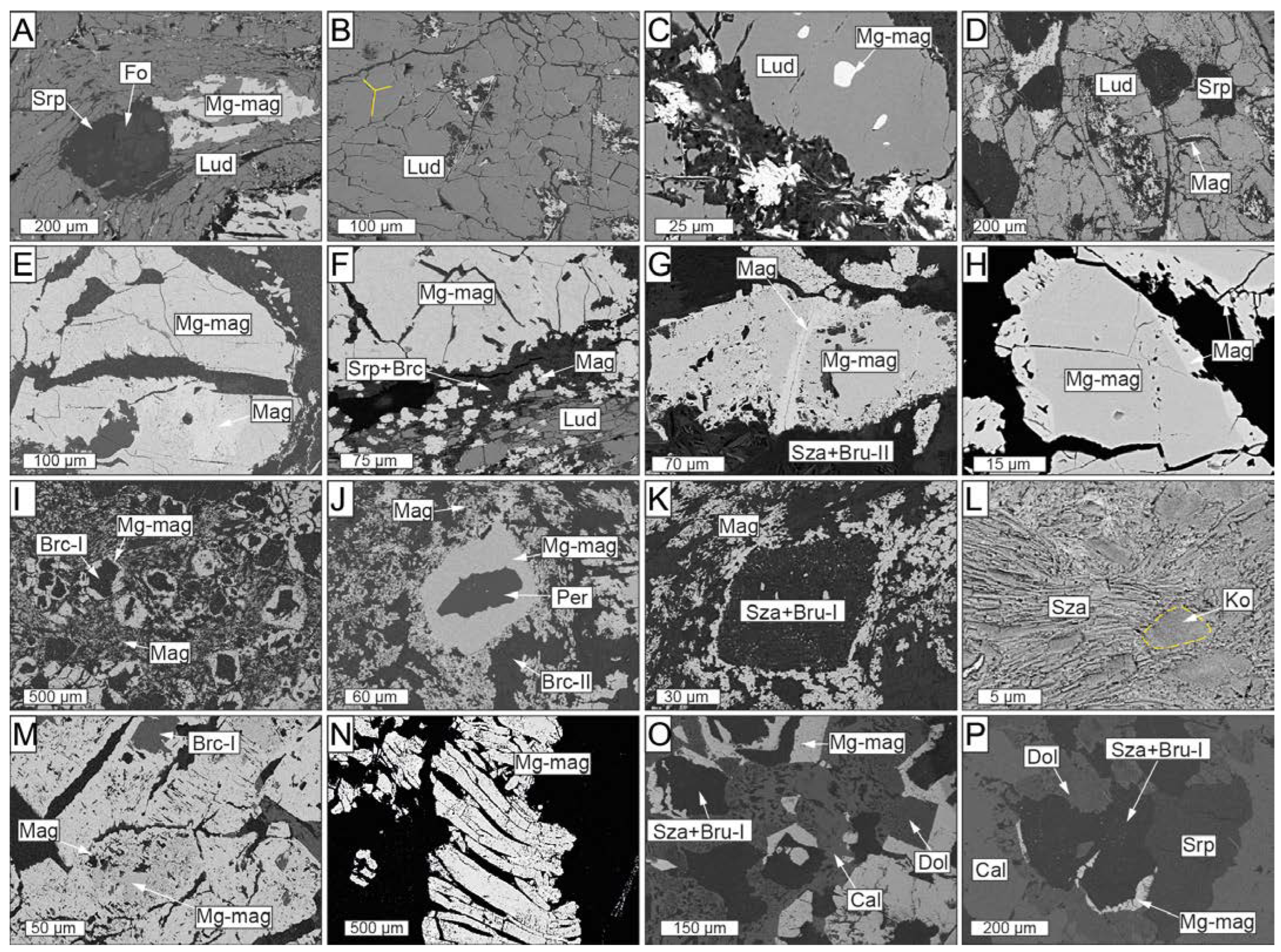
Ludwigite shows a string of grey–brown to grey–pink pleochroism and a marked blue-to-pink–white anisotropy when observed under a reflected light microscope (Figure 4A). It occurs as massive masses of fibrous or prismatic crystals up to 1.5 mm in size, forming parallel, radiating, or interwoven aggregates including partially serpentinized olivine and/or Mg-rich magnetite crystals (Figure 4B and Figure 5A–D). Ludwigite is commonly deformed, forming curved and elongated crystals, particularly in the upper portion of the zone, close to the contact with the Ronda Peridotites (Figure 4B). However, ludwigite crystals that locally form 120° triple junctions have also been found (Figure 5B), defining a polygonal structure. Some ludwigite crystals show partially dissolved cores, infilled by an intergrowth of Mg-rich magnetite and fine-grained, fibrous, or flake-like hydrotalcite group minerals (Figure 5D). A mixture of cataclasized ludwigite crystals occasionally fills a network of fractures among euhedral Mg-rich magnetite (Figure 4C).
The Mg-rich magnetite exhibits different textures within the ludwigite–magnetite zone: (1) Mg-rich cores partially replaced by magnetite along fractures and boundaries, characterized by sharp contacts and porous texture (Figure 5E–H); (2) masses of anhedral Mg-rich magnetite filling cracks and voids in ludwigite (Figure 5A); and (3) euhedral crystals partially replaced by magnetite with brucitized cores after periclase (Figure 5I) that dominate the lower portion of the ludwigite–magnetite zone. In the latter, Mg-rich magnetite grains with no fractures preserve cores of periclase as well as tiny, euhedral periclase inclusions (up to 20 µm sized) (Figure 5J).
Magnetite is widespread as rough and uneven fragments dismembered within the matrix as well as replacing Mg-rich magnetite grains (Figure 5E–H). Tiny, spherically shaped magnetite particles with diameters of <10 nm are usually included in szaibelyite+brucite pseudomorphs (Figure 5K), as well as in brucitized cores of Mg-rich magnetite.
Small 2–5 μm kotoite relicts are partially replaced by bunches of tabular or flaky-like szaibelyite crystals which are, in turn, replaced by and/or intergrowth with brucite-II (Figure 5L). Wightmanite and coalingite are some rather scarce minerals occurring as small acicular crystals intergrown with brucite-II and/or szaibelyite.

4.2.2. Magnetite-Szaibelyite Zone

The mineral assemblage in this zone includes Mg-rich magnetite, magnetite, brucite, szaibelyite, serpentine, chondrodite, schoenfliesite, dolomite, calcite, hydromagnesite, and coalingite.
In this zone, the mineralization consists of irregular lenses and stretched and folded bands of nearly monomineralic Mg-rich magnetite and magnetite up to 10 cm in width, exhibiting pull-apart fractures (Figure 3D,E). The ore lenses and bands are usually associated with white-colored groundmasses of brucite-II and szaibelyite with minor serpentine, calcite, and dolomite, especially in the upper portion of the szaibelyite–magnetite zone, towards the south of the deposit (Figure 3F). Here, brucite-II and szaibelyite form aggregates of intergrowth fibrous crystals locally crosscut by late serpentine and calcite veins. Where szaibelyite and brucite groundmasses are absent, magnetite mineralization occurs as thinner folded bands and disseminations hosted in a chondrodite-bearing dolomitic marble. Chondrodite forms subhedral pale-yellow crystals up to 3 mm in size systematically associated with magnetite bands (Figure 3G).
The mineralized lenses and bands are composed of Mg-rich magnetite crystals (up to 1 mm in size) almost entirely replaced by porous magnetite along fractures and boundaries (Figure 5M). The Mg-rich magnetite crystals are normally elongated and deformed in a ductile-brittle manner and broken through sets of parallel pull-apart fractures (Figure 5N). In the lower portion of the szaibelyite–magnetite zone, the Mg-rich magnetite edges of former euhedral grains are preserved, the cores of which consist of brucite-I after periclase including tiny magnetite crystals. Dolomite here coexists with calcite forming complex replacive textures as well as forming rims around the edges of Mg-rich magnetite grains (Figure 5O,P). Narrow, colorless calcite veins, as well as acicular or needle-like hydromagnesite or coalingite tiny crystals smaller than 50 µm, fill late veins crosscutting the whole szaibelyite–magnetite zone.
The host rock of the magnetite–szaibelyite zone is a periclase marble. Here, homogeneously distributed periclase grains coexist with brown–dusty irregular calcite crystals with perfectly marked rhombohedral cleavage exhibiting pale-green to pale-pink interference colors (Figure 4G–I). It is worth noting that irregular bands of brucitized periclase show sharp contact with the periclase marble.

4.3. Mineralogy of the Reaction Zone and Migmatites

The contact between the skarn and the migmatites of the Blanca Unit is defined by a reaction zone or black wall made up of green amphibolite. The amphibolite is mostly made of a granoblastic aggregate of euhedral to subhedral crystals up to 2 mm in size, of the tremolite-actinolite series. This aggregate is partially replaced by fibrous tremolite-actinolite series amphiboles up to 0.5 mm in size (Figure 4J,K). Locally, up to 2 mm euhedral actinolite are embedded within, and partially replaced by, a microcrystalline, fibrous-like groundmass of crystals of the tremolite-actinolite solid solution (Figure 4L).
Structurally below the amphibolite reaction zone, and towards the carbonates of the Las Nieves unit, there are diatexitic garnet- and cordierite-bearing migmatites. Migmatites are composed of quartz, K-feldspar, plagioclase, cordierite, garnet, biotite, and minor sillimanite, with accessory apatite, zircon, ilmenite, and magnetite. Closer to the contact with the skarn, the migmatite shows a magmatic foliation defined by the alternation of decimetric to metric leucosomes and melanosomes, and the alignment of biotite and sillimanite. Close to the Las Nieves unit, migmatite on top of the carbonates shows a gneissic appearance, mostly due to subsolidus ductile deformation at the contact.

4.4. Mineral Chemistry

Ideal ludwigite is the Mg2+, Fe3+ borate end member of the vonsenite (Fe2FeBO5)-ludwigite continuous isomorphous series. In its orthorhombic structure, the cations are six-fold coordinated and occupy four crystallographically independent sites, M1, M2, M3, and M4, which share edges. Fe2+-Mg exchange occurs in M1, M2, and M3, whereas Fe3+ may partially be substituted by Al, Sn, Sb, Ti, and V in the M4 site by simple o coupled substitutions [52,53,54,55]. Such exchanges are attested by the strong negative correlation between Fe2+ and Mg and between Fe3+ and Al + Ti. The range of MgO in ludwigite is restricted between 30.14–34.93 wt.% and that of FeOt to 44.18–49.70 wt.% with a negative correlation between them (Figure 6A) whereas B2O3 varies significantly from 13.97–19.51 wt.%, showing a positive correlation with MgO (Figure 6B). Ludwigite is relatively rich in Al2O3 and TiO2, with contents ranging from 0.98–2.06 wt.% and up to 2.32 wt.%, respectively.
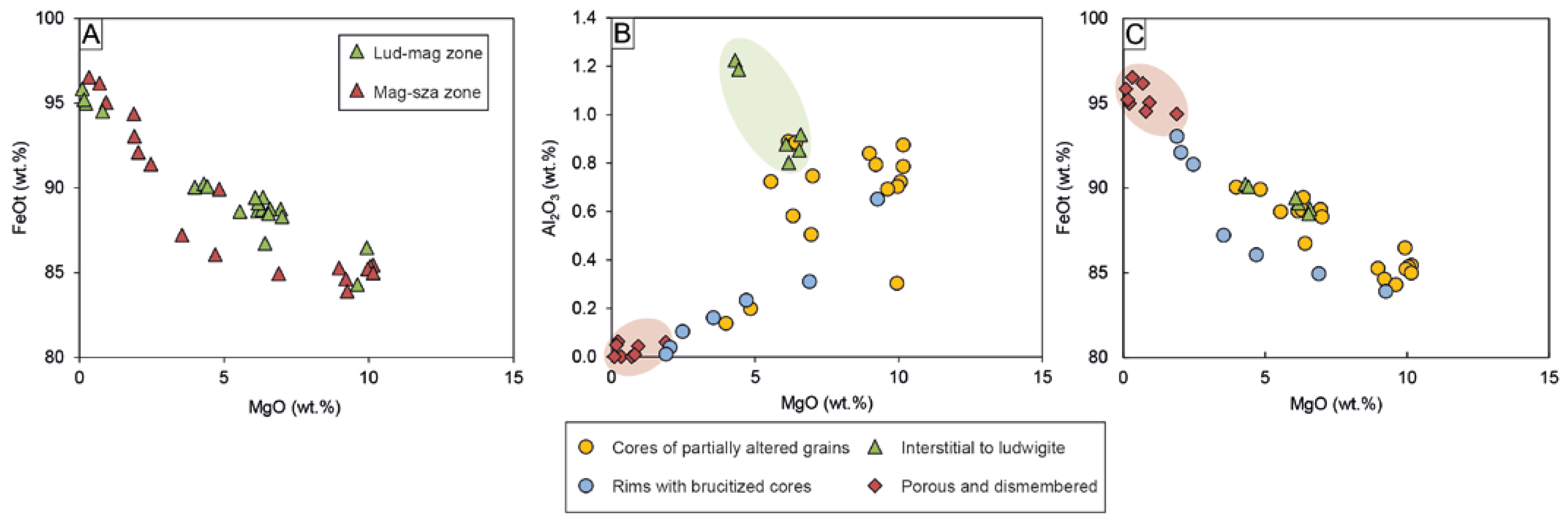
Mg-rich magnetite and magnetite are widespread throughout the whole deposit. Although there are no compositional differences between oxides located in the ludwigite–magnetite zone and those of the magnetite–szaibelyite zone (Figure 7A), chemical variations have been noted according to the different textures, independently of their location within the skarn. As mentioned above, Mg-rich magnetite (i.e., Mg# > 0.1) exhibits three different textures: (1) cores of grains partially altered to magnetite, (2) anhedral grains interstitial to ludwigite, and (3) euhedral crystals with brucite after periclase cores. On the other hand, magnetite occurs as porous crystals replacing Mg-rich magnetite as well as dismembered grains within the matrix. All the different-textured Mg-rich magnetite are rich in MgO (up to 10.15 wt.%); however, the euhedral crystals with brucite cores are moderately richer in FeOt (83.89–93.04 wt.%) compared to cores of Mg-rich magnetites (80.73–90.05 wt.%) and interstitial to ludwigite (88.47–90.24 wt.%), the latter being enriched in Al2O3 (0.80–1.22 wt.%) (Figure 7B). On the other hand, porous and dismembered magnetite replacing Mg-rich magnetite is poor in MgO (0.09–2.16 wt.%) and Al2O3 (up to 0.06 wt.%) but rich in FeOt (92.45–96.53 wt.%) (Figure 7B,C). Both SiO2 (up to 1.09 wt.%) and TiO2 (up to 0.32 wt.%) contents are homogenous within all magnetite grains.
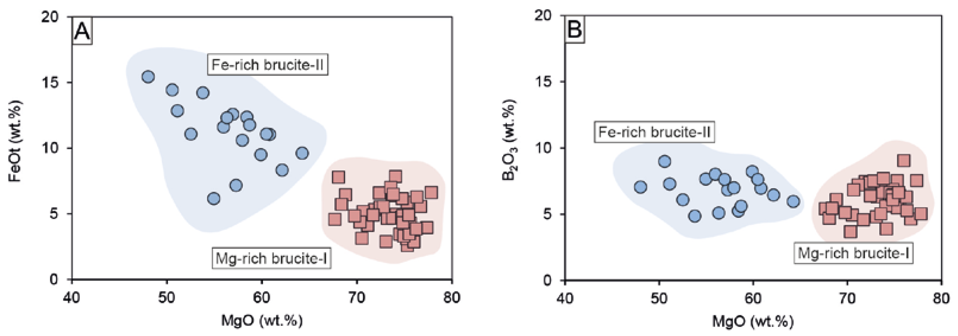
Brucite is much more abundant in the magnetite–szaibelyite zone than in the ludwigite–magnetite zone. As mentioned above, there are two types of brucite, an early Fe-poor brucite-I, and a later Fe-rich brucite-II, much less abundant than the former. The FeO content of brucite-I ranges between 2.59 and 7.85 wt.% and that of brucite-II between 6.18 and 15.45 wt.%, as can be seen in Figure 8A. Both brucite-I and brucite-II always had similar FeO and MgO contents irrespective of the skarn zone. In addition, both types of brucite display similarly high B2O3 contents ranging from 3.67 to 9.04 wt.% for brucite-I and 4.86–8.98 wt.% for brucite-II (Figure 8B). After Aleksandrov [58], the presence of boron in brucite can be related to the isomorphic incorporation following the scheme 3(OH) → [BO3]3– during endogenous borates replacement, thus reducing the OH- content in brucite. This is attested to by the low H2O contents of brucites compared to stoichiometry (i.e., ~30.89 wt.%). According to the calculations of the OH content of brucite after endogenous borates following the method by Aleksandrov [58], the OH content was calculated as the difference between B2O3 in the theoretical borate composition (i.e., 17.8% in ludwigite) and the measured B2O3 and by applying a correction factor (0.867) resulting from the recalculation of 3(OH)- = [BO3]3-. The results of this calculation point towards brucite-I formed by ludwigite replacement, as the sum of the total cations and calculated OH after ludwigite is the closest to 100%, compared to OH calculations for kotoite. The variation from 100% could be ascribed to EPMA accuracy or mass unbalance by lack of Fe2O3 calculations. Mixed analyses of both szaibelyite and brucite could also be an explanation for such a deviation. On the other hand, the calculated OH (wt.%) contents of brucite after kotoite and suanite were higher than expected, as they broadly exceeded 100% total oxide. Szaibelyite exhibits B2O3 contents ranging from 34.10 to 58.10 wt.%, with no differences between that located in the ludwigite–magnetite zone and that of the magnetite–szaibelyite zone. The MgO content is quite homogeneous (40.72–49.42 wt.%), whereas FeOt varies from 0.85 to 7.06 wt.%.
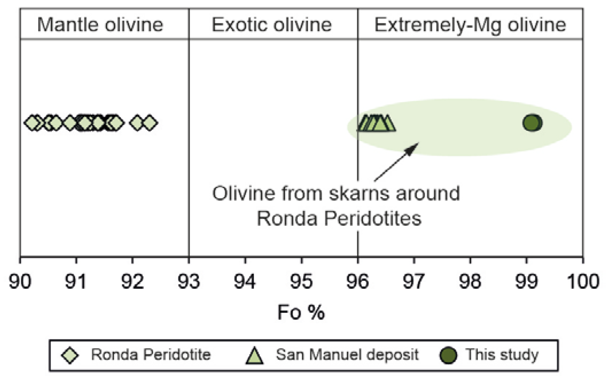
The EPMA analyses of forsterite were carried out in cores of the grains far away from serpentinized areas in the ludwigite–magnetite zone. They are chemically quite homogeneous with MgO ranging from 54.80 to 55.85 wt.% and FeO from 3.54 to 3.94 wt.%. The forsterite content is systematically over 96 (Fo96-Fa4) (Figure 9), so they may be considered extremely magnesian olivine, according to Plechov et al. [59].
The minerals belonging to the reaction zone are intermediate members of the tremolite–actinolite series. They are chemically homogeneous with MgO ranging from 16.6 to 23.1 wt.%, SiO2 from 52.6–58.7 wt.% and CaO from 10.8 to 13.2 wt.%. FeO contents are more variable, ranging from 3.5 to 13.0 wt.%, although no chemical variations have been noted between the different amphibole generations. It is worth noting that qualitative analyses carried out in some amphibole grains have revealed the presence of boron.

4.5. Solid Mineral Inclusions in Oxides

The study of inclusions was carried out in Mg-rich magnetite from the ludwigite–magnetite zone (sample ROB-21) and in the magnetite–szaibelyite zone (sample ROB-24).
One FIB thin foil (profile A-A’ in Figure 10A,B) was cut across an inclusion in Mg-rich magnetite from the ludwigite–magnetite zone, which was previously identified employing energy-dispersive X-ray spectroscopy (EDS) analysis with a field emission scanning electron microscope (FE-SEM), as a complex compound with Mg, Fe, and Si. The HAADF image of the cross-section revealed the coexistence of several different individuals (Figure 10B). The TEM-EDS elemental mapping shows that the left portion of the inclusion is a Mg-rich mineral, whereas in the right part, it coexists with a Si-rich one. HRTEM investigations were carried out at the contact of the Mg-rich phase with the hosting Mg-rich magnetite (rectangle 1 in Figure 10C). The measured d-spacing of 2.10Å for the Mg-rich phase corresponds with the ideal 2.105 Å (200) of periclase [60] (Figure 10D,E). Selected area electron diffraction (SAED) patterns were acquired at the contacts between the Si-rich member of the composite inclusion and host Mg-rich magnetite (rectangle 2 in Figure 10C). The SAED patterns of the Si-rich inclusion yielded measured d-spacings of 2.64 Å and 7.35 Å (Figure 10F,G), resembling the ideal d-spacing of 2.638 Å (-131) and 7.329 Å (002) of chrysotile [61]. Some basal orientation of serpentine in the thin foil was also noted in the sample (see diffuse rings in Figure 10G).
A second thin-foil (profile A-A’ in Figure 11) crosscutting large inclusion within Mg-rich magnetite from the magnetite–szaibelyite zone was also studied. This thin foil intersected an inclusion consisting of Mg-rich and Ca-rich members exhibiting straight boundaries with hosting Mg-rich magnetite (Figure 11B,C). The SAED patterns were acquired at the contact between the two members (Figure 11D). The measured d-spacing of 2.09 Å (Figure 11E) corresponds to 2.105 Å (200) of periclase. Calcite was identified by a measured d-spacing of 3.03 Å (Figure 11F) corresponding to the ideal 3.035 Å (104), as defined by Graf [62].

4.6. Microstructure of the Ores

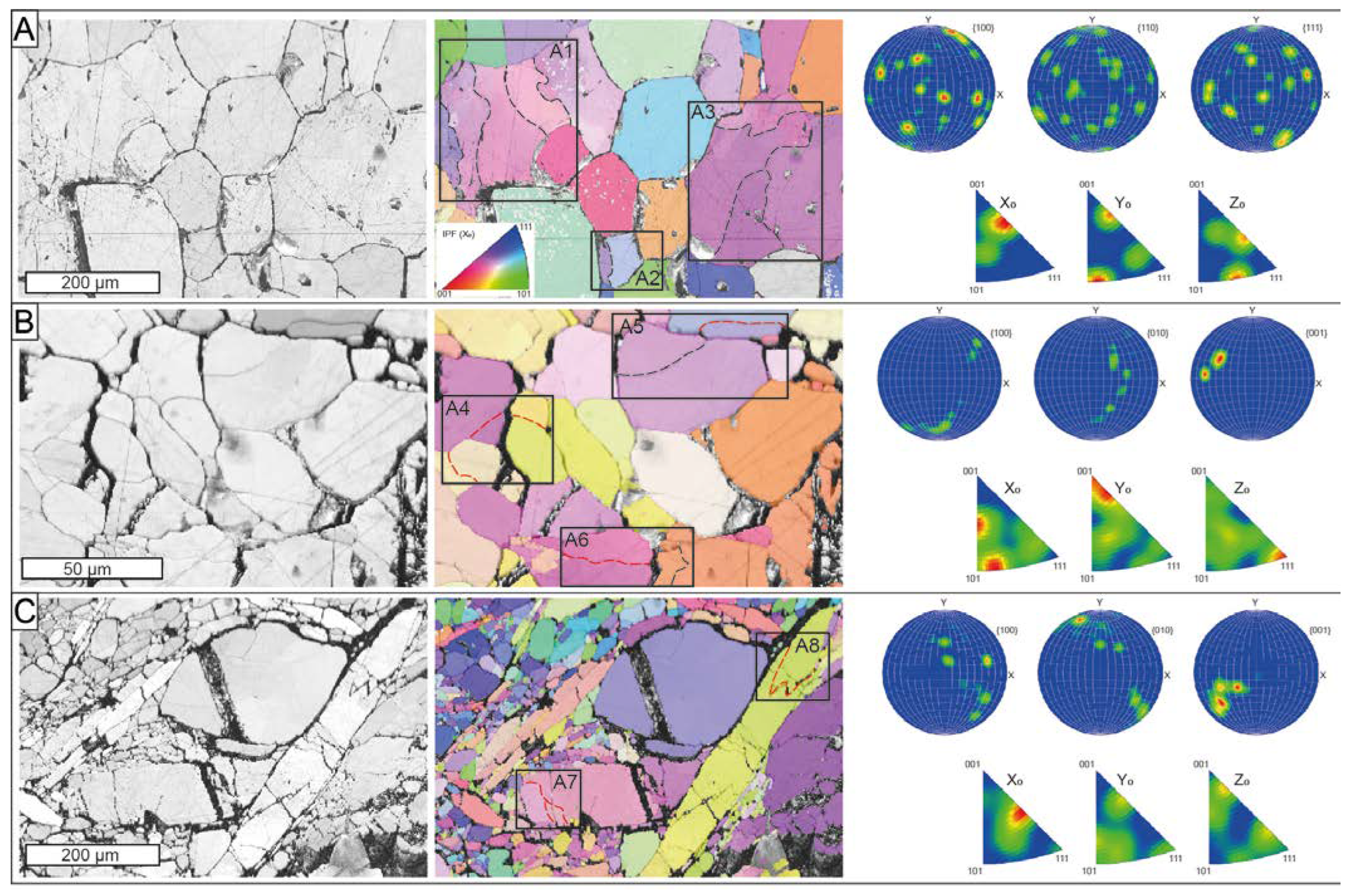
Three EBSD maps were performed on selected areas from the massive Mg-rich magnetite with a polygonal microstructure (ROB-3) and massive ludwigite (ROB-2) from the ludwigite–magnetite zone (Figure 12). The massive Mg-rich magnetite sample consisted of medium-grained crystals (up to 0.4 mm) exhibiting a 120° triple junction with straight boundaries (Figure 12A). The BC and IPF map revealed the coexistence of irregular grains having appreciable internal crystal bending (rectangles A1 to A3 in Figure 12A) with slightly smaller but completely euhedral, free-of-strain Mg-rich magnetite grains. The internal crystal bending is marked by low-angle (<5°), subgrain boundaries within the grains, whereas the misorientation between grain boundaries was higher than 15°. The inverse pole figure acquired in 3D space reference X0, Y0, and Z0, displays near random to weak patterns of bulk CPO of the grains with several orientation maxima crystallographic preferred orientation (CPO) patterns, with numerous orientation maxima at (100), (110), and (111) (Figure 12A).
The BC and IPF maps acquired from the massive ludwigite reveal two texturally different areas: (1) massive, granoblastic ludwigite (Figure 12B), and (2) porphyroclastic, deformed, and elongated ludwigite crystals (Figure 12C).
The granoblastic ludwigite is composed of fine-grained (<50 µm) crystals with a poorly defined polygonal microstructure with subhedral grains forming 120° curved junctions (Figure 12B). It also exhibits the coexistence of free-of-strain grains, with the grains showing internal crystal bending defined by subgrain boundaries. However, the misorientation of such subgrain boundaries ranged from low-angle to medium-angle boundaries (rectangles A4 to A6 in Figure 12B). The pole figures reveal a strong CPO of the grains, especially at (001) (Figure 12B) On the other hand, porphyroclastic ludwigite is composed of large (up to 1 mm) deformed and elongated crystals coexisting with both deformed and rounded porphyroclasts (up to 0.3 mm) and small equigranular neoblasts with no internal deformation. Neoblast formed high-angle boundaries and exhibited almost the same size as subgrain in the large and deformed porphyroclasts (see rectangle A7 in Figure 12C). Subgrain boundaries in deformed and elongated porphyroclasts were systematically medium-angle boundaries (rectangles A7 to A8 in Figure 12C). The pole figures reveal a strong CPO of the ludwigite grains (Figure 12C). Open fractures partially filled with hydrotalcite group minerals were common in the ludwigite samples.

5. Discussion

5.1. Skarn Topology

As stated above, the El Robledal deposit is an ore body with two contrasting zones: the uppermost zone dominated by massive ludwigite, Mg-rich magnetite, and magnetite (i.e., ludwigite–magnetite zone) close to the tectonic contact with the Ronda Peridotites; lower zone (i.e., magnetite–szaibelyite zone) dominated by Mg-rich magnetite, magnetite, and szaibelyite hosted in dolomitic marble. Accounting for that mineralogy we suggest that the El Robledal deposit is an Mg-Fe-B skarn deposit in the terms defined by Marincea and Dumitras [14] and not a magnesian exoskarn of magnetite–ludwigite, as suggested previously by Curras and Torres-Ruíz [63]. Noteworthy is that similar mineral assemblages have been previously noted in other borate-bearing Mg-skarns included in the Mg-Fe-B type, particularly in the Banatitic Magmatic and Metallogenetic Belt [14].

5.2. Mineral Paragenesis and Skarn Evolution

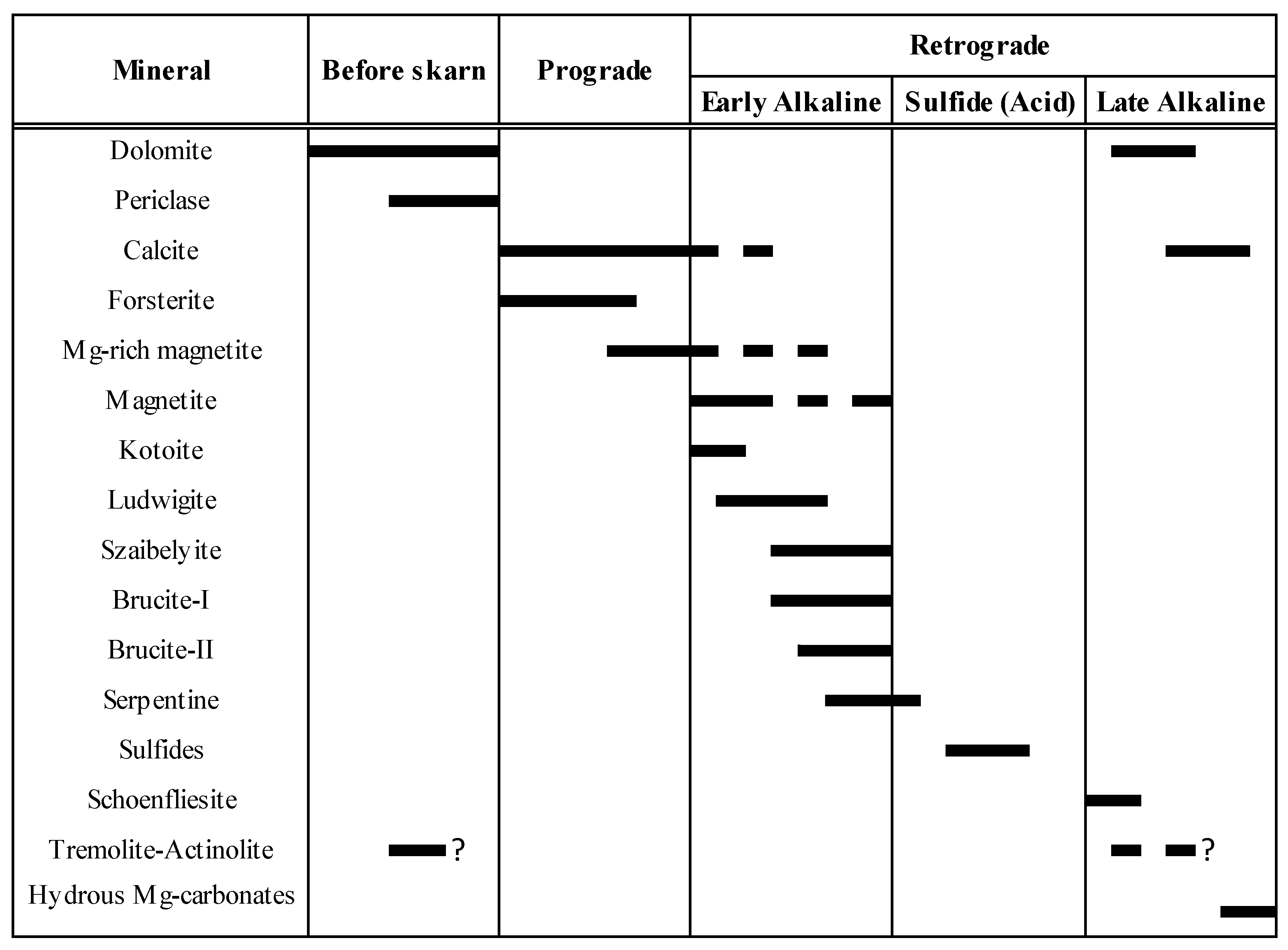
Figure 13 summarizes the proposed paragenetic sequence for the El Robledal deposit.

5.2.1. Metamorphic Stage

In the El Robledal area, periclase is widespread and homogeneously distributed in the dolomitic marble samples free of mineralization (Figure 4G–I). Moreover, crystals of periclase are systematically included in Mg-rich magnetite in both the ludwigite–magnetite and magnetite–szaibelyite zones (Figure 10 and Figure 11). Interestingly, periclase is associated with calcite in the magnetite–szaibelyite zone. This may indicate that periclase was an early-formed mineral unrelated to the infiltration of mineralized fluids (i.e., metamorphic origin), as suggested in other similar skarns worldwide [3]. This mineral may effectively form in anhydrous conditions (i.e., XCO2 = 1) upon increasing temperature via thermal decomposition of dolomite at temperatures above 610 °C at 1–2 kbar [64,65,66] according to the following reaction:
CaMg(CO3)2 = MgO + CaCO3 + CO2
From the observations above, we suggest that periclase was the first mineral to form under dry conditions by metamorphism of the Blanca Unit carbonate rocks during the hot emplacement of the Ronda Peridotites.

5.2.2. Prograde Stage

Forsterite is systematically embedded in masses of both Mg-rich magnetite and ludwigite crystals and exhibits well-developed shapes (Figure 4A,C); therefore, it may be considered one of the earliest minerals formed. This is in concordance with the scheme proposed by Aleksandrov [3] for Mg-skarn formation in which forsterite + calcite form the primitive metasomatic zoning by the interaction of dolomite with silica-bearing hydrothermal fluids, according to the following reaction:
CaMg(CO3)2 + 0.5H4SiO4 = 0.5Mg2SiO4 + CaCO3 + H2O + CO2
The analyzed forsterite had a very high Mg# (>96) unlike forsterite from the country Ronda Peridotites (Mg# < 93), suggesting a metasomatic origin related to fluid infiltration [59]. Mazzoli et al. [46] estimated that forsterite in dolomitic marble from the las Nieves Unit originated from fluid-driven replacement reactions at ~510°, which is fully consistent with temperatures of 550–600 °C, proposed for the formation of forsterite in B-bearing skarns worldwide [67] and in the nearby Mg-Fe skarn deposit of San Manuel, also located in the Blanca Unit [30].
In most Mg-skarns, forsterite is usually isothermally replaced by diopside giving rise to primitive zoning, thus evidencing an increasing aSiO2 in the system [68,69]. However, this mineral was not detected in our studied rocks, which may indicate low aSiO2, similar to those reported in other Mg-skarns worldwide that are spatially related to both basic and ultrabasic rocks—e.g., Skye Island, Scotland; Bor-Uryakh, Yakutia, Russia [3]; and San Manuel in southern Spain, [30].
Mg-rich magnetite is locally included in ludwigite (Figure 5C) suggesting its formation before the early alkaline phase of the retrograde stage [3]. On the other hand, cores of Mg-rich magnetite are made of brucitized periclase at the lower part of the ludwigite–magnetite zone. This, along with periclase inclusions in Mg-rich magnetite, allows us to constrain its formation after periclase and before ludwigite, quite probably starting at the end of the prograde stage and continuing during the early alkaline phase of the retrograde stage. Mg-rich magnetite is systematically altered to porous magnetite showing sharp and irregular contacts (Figure 5E–H). This texture suggests coupled dissolution and reprecipitation processes (CDR) [70] that promoted Mg removal and Fe enrichment. Moreover, cracks and voids of ludwigite are partially filled with Mg-rich magnetite, suggesting the circulation of Fe-bearing fluids or magnetite remobilization after ludwigite formation, during the retrograde stage. This observation is consistent with reports in the literature where the formation of Mg-rich magnetite in skarns is related to the retrograde stage of skarns, especially with the early alkaline phase [3]. In fact, Pavlov [71] stated that magnesioferrite formation is promoted by alkaline conditions at very low pressures. However, Aleksandrov [3] pointed to the possibility of magnesioferrite formation during the prograde stage. This was also noted by González-Pérez et al. [30] in the San Manuel skarn. They suggest that both magnesioferrite and their replacement by magnetite took place at increasing temperatures during the prograde stage. Moreover, they approximate a minimum temperature for the prograde stage thermal peak of ~650 °C based on spinel exsolution within magnetite.
Kotoite has been locally found as small, rounded crystals almost completely replaced by szaibelyite (Figure 5L). Kotoite formation by dolomite replacement has been proposed by Watanabe [72], according to the reaction:
3CaMg(CO3)2 + 2B(OH)3 = Mg3(BO3)2 + 3CaCO3 + 3CO2 + 3H2O
Barsukov and Deryugina [73] experimentally confirmed this reaction at 400 °C for alkaline B-bearing solutions. The presence of kotoite is indicative of hypabyssal conditions (i.e., at depths lower than 2–3 km) [3], which agrees with the occurrence of periclase.
Kotoite is scarce whereas ludwigite is widespread in the ludwigite–magnetite zone forming massive ores along with magnetite. This is indicative of a high Fe concentration in ore fluids percolating through the El Robledal. According to Barsukov and Egorov [74], the presence of Fe in the hydrothermal fluids would enhance ludwigite formation. In fact, these authors suggest that Fe fixed in magnetite seems to be the main reason for ludwigite abundance in most of the Mg-skarn deposits of Romania. The effect of Fe in mineralizing fluids to enhance ludwigite formation was indirectly demonstrated by the experiments of Bloise et al. [55]. As noted before, the formation of ludwigite has been traditionally ascribed to the early alkaline phase of the prograde stage [3]. According to Grigorev and Nekrasov [75], ludwigite forms at temperatures above 450–500 °C by dolomite replacement in a Fe-bearing system according to:
Fe3O4 + 3CaMg(CO3)2 + B2O3 = 2(Mg,Fe)2Fe(BO3)O2 + 3CaCO3 + 3CO2
Similar temperatures (i.e., 500–650 °C) were stated by Kravchuk et al. [76] in their synthesis of Fe-ludwigite with a Fe molar fraction of 25% (i.e., f = 25%). Marincea [56] obtained temperatures around 600–650 °C for ludwigite formation in the Ocna de Fier deposit, Romania. Later, Bloise and Barrese [77] reported equivalent temperatures experimentally. They noted that Fe-bearing ludwigite formed systematically over 550 °C at both 0.5 and 1 kbar in the MgO-FeO-Fe2O3-B2O3 system for mixtures rich in MgO, as expected in the El Robledal deposit. However, Bilohuščin et al. [13] in the Vysoká-Zlatno deposit, Slovakia, stated that ludwigite formed during the prograde stage at 700 °C and 0.7 kbar. According to these statements, ludwigite in the El Robledal deposit should have formed at temperatures above 500–550 °C, after kotoite, Mg-rich magnetite, and periclase. This range of temperature marks almost the highest temperatures of the early alkaline stage, falling from, and quite close to, that of the thermal peak of the prograde stage. This is in line with temperatures falling from ~650 °C reached during the thermal peak of the prograde stage of the San Manuel skarn [30]. This is in accordance with temperatures estimated for the anatexis of crustal rocks of the Blanca Unit during the Ronda Peridotites emplacement (600–750 °C at ~3 kbar) [33,45]. On the other hand, according to Bloise et al. [55], the presence of small amounts of Al in the system can reasonably increase the temperature of ludwigite crystallization up to 700 °C, diminishing ludwigite formation. Thus, the dominance of ludwigite in the El Robledal deposit suggests a low activity of alumina in the mineralizing fluids.

5.2.3. Retrograde Stage

During the evolution of the retrograde stage in borate-bearing Mg-skarns, the anhydrous minerals are usually replaced by hydrated ones. Fe-bearing ludwigite (f = 34–21%) and kotoite are systematically replaced by szaibelyite. Kotoite is replaced by szaibelyite following the reaction:
Mg3(BO3)2 + 2H2O = 2MgBO2(OH) + Mg(OH)2
However, szaibelyite commonly occurs associated with brucite-I hosting micrometric magnetite crystals (Figure 5K) in the El Robledal deposit. Barsukov and Kuril’chikova, [78] suggested that ludwigite is transformed to szaibelyite, magnetite, and brucite at temperatures below 300 °C down to 160 °C according to:
6Mg2Fe(BO3)O2 + 9H2O = 3Mg2(B2O4OH)(OH) + 2Fe3O4 + 6Mg(OH)2 + 0.5CO2
Similar szaibelytization of ludwigite with f = 25% was proposed by Pertsev [79], according to the reaction:
2(Mg0.75Fe2+0.25)Fe3+(BO3)O2 + 2H2O = Mg2(B2O4OH)(OH) + Fe3O4 + Mg(OH)2
The decomposition of ludwigite to form fibrous szaibelyite along with fine-grained magnetite was also noted by Peng and Palmer [80]. The presence of such pseudomorphs was already noted by Pertsev [81] and Aleksandrov [82].
On the other hand, brucite-I also forms banded textures in periclase marbles (Figure 4I). This textural evidence reveals that brucite-I replaces periclase in nonmineralized rocks following the reaction:
MgO + H2O = Mg(OH)2
Such a fluid infiltration-driven process is very likely related to zones of higher permeability in the periclase marble rocks as a result of weakness promoted by deformation.
Brucite-I replacing periclase is interpreted as an earlier phase compared to brucite-II, which forms groundmasses along with szaibelyite and minor serpentine. Brucite-I and brucite-II have similar B2O3 whereas brucite-II has higher Fe contents compared to brucite-I (Figure 8). According to Aleksandrov [58], the hydration of high-temperature borates and szaibelyite led to the formation of B-bearing brucites. However, we could not ascribe the formation of B-bearing brucite to high-temperature borate replacement and, thus, their formation may be explained by the infiltration of B-bearing fluids through the El Robledal during the retrograde stage. As Fe contents in brucite-II are higher than those of brucite-I, we suggest that Fe content in fluids should have decreased during evolving retrograde stage. This could be ascribed to serpentinization, which is normally accompanied by an increase of aFe in the fluid.
Serpentinized forsterite is widespread in the El Robledal deposit embedded within the ore masses (Figure 4A), as well as included in Mg-rich magnetite (Figure 10). Moreover, late serpentine-rich veins crosscut the mineralization in the magnetite–szaibelyite zone. This manifests the late origin of serpentine as a consequence of forsterite replacement according to:
4Mg2(SiO4) + 6H2O = Mg6(Si4O10)(OH)8 + 2Mg(OH)2
The acid stage is poorly represented due to the almost complete lack of sulfides. Some schoenfliesite grains have been locally found in the El Robledal deposit. Its formation has been traditionally ascribed to late retrograde stages and low temperatures <260 °C [83], which allows us to relate its formation to the late alkaline phase of the retrograde stage [84].
The former reactions promote a subsequent CO2 excess of the system, which should be consumed in carbonation reactions. Nevertheless, the preservation of brucite in the El Robledal deposit is indicative of an open system in which CO2 can break out of it. Moreover, according to Ferry and Rumble [65] and Simandl et al. [66], low XCO2 avoids the destabilization of brucite to form retrograde dolomite during the late retrograde stage. The formation of retrograde dolomite is locally observed in zones of the magnetite–szaibelyite zone according to:
CaMg(CO3)2 + H2O = Mg(OH)2 + CaCO3 + CO2
In these zones, brucite-I pseudomorphs after periclase in direct contact with calcite develop rings of dolomite (Figure 5P), similar to textures described by Simandl et al. [66]. Brucite destabilization promoted CO2 consumption leading to its transformation into hydrous Mg carbonates—e.g., [85]. This could explain the occurrence of late veins filled with acicular hydrotalcite-group minerals, as well as late calcite veins crosscutting the whole deposit. It is assumed that these late veins represent the escape conduits liberating CO2 from the system.

5.3. Effects of Deformation

All analyzed samples exhibited grains with variable intracrystalline deformation developing subgrain boundaries (rectangles A1 to A8 in Figure 12), which is indicative of crystal–plastic deformation.
The massive Mg-rich magnetite sample showed a well-developed foam-like, polygonal microstructure, where internally deformed grains with low-angle subgrain boundaries cohabited with undeformed grains developing a 120° triple junction. This microstructure is indicative of a high grade of recrystallization (i.e., annealing) after crystal–plastic deformation [70,86,87,88,89,90,91,92]. The foam-like, polygonal texture has been related either to (1) high-temperature annealing in a closed system [93] or to (2) fluid-assisted replacement in an open system [94,95]. Here, Mg-rich magnetite is systematically replaced by porous magnetite with sharp contacts, along boundaries and fractures, suggesting CDR process, which is indeed indicative of fluid-assisted replacement [70]. Moreover, the occurrence of folded magnetite bands with pull-apart fractures filled with szaibelyite and brucite (Figure 3D–G) indicates that deformation was active during ore formation. The fluid-assisted replacement of ores in the El Robledal is in concordance with the interpretation of similar microstructures observed in the nearby San Manuel skarn [30]. Moreover, the absence of newly formed grains and the low-angle subgrain boundaries in the deformed grains from the Mg-rich magnetite sample point toward high-temperature grain boundary migration (GBM) followed by strong annealing [96]. Thus, high temperatures would have been preserved allowing oxides to recrystallize almost completely.
In the porphyroclastic ludwigite, elongated and/or internally deformed coarse grains are accompanied by free-of-strain neoblasts of apparently homogeneous size (similar to the subgrains size in porphyroclasts) Moreover, the sample exhibited a strong CPO pattern. These microstructures are also indicative of deformation and subsequent dynamic recrystallization processes by subgrain rotation (SGR) at intermediate temperatures and intermediate to high strain rates [91,96].

5.4. Source of Boron

The measured B2O3 content in borates present in the El Robledal deposit ranged from 13.97 to 19.51 wt.% in ludwigite and 32.62–58.02 wt.% in szaibelyite. The formation of these borates is with the percolation of B-bearing fluids through dolomitic marble and subsequent metasomatism. [3]. The source of these fluids in other B-bearing skarn deposits has been carried by hydrothermal fluids responsible for skarn formation. The source of these B-bearing fluids in other B-bearing skarn deposits has been traditionally ascribed to volatile-rich fluids released from the surrounding cooling igneous intrusions of intermediate to acid composition—e.g., [3]. In the vicinity of the El Robledal area, the only igneous-related rocks are migmatites and a thin leucogranite dike approximately 10 cm wide located to the north of the deposit. The origin of leucogranites in the area has been associated with the partial melting of migmatites during the emplacement of Ronda Peridotites [43,45,97].
Acosta-Vigil [43] detected relatively high B concentration (~30 ppm) in migmatites around Ronda Peridotites compared with other Hercinian migmatites (~20 ppm) [98]. According to Moran et al. [99], as the metamorphism of pelitic and/or quartz-feldspathic rocks progress, the B content in the rocks decreases. Thus, the destabilization of phyllosilicates and/or tourmaline and dehydration of the metapelite/migmatite with progressive metamorphism may promote the partitioning of B into the escaping fluid/melt phase [100,101].
Later, Acosta-Vigil et al. [102] identified relatively high B contents ranging from 3.6 to 5.7 ppm in equivalent migmatites located west of the town of Istán (see Figure 1), whereas these contents increased up to an average of 400 ppm (with 1250 ppm maximum) in anatectic leucogranites derived from the mentioned migmatites. It would be necessary for a B-enriched protolith to generate leucogranites with such high B contents. Tourmaline textures and chemical analyses of B2O3 in leucogranites led these authors to suggest a high initial B concentration in the parental melts of the leucogranites (i.e., migmatite). Moreover, [97] assessed that B from leucogranites could be lost to the country rock since miarolitic cavities are frequent and serpentinites in the contact between peridotites and such dikes are B enriched. A notable B concentration (up to 619 ppm) was also found by Pereira et al. [98] in tourmaline-bearing leucogranites crosscutting Ronda Peridotites. They also noted that Ronda Peridotites are notably enriched in B (1 ppm on average) compared to mantle composition [103]. Moreover, these values increase significantly in serpentinites contiguous to leucogranite outwards from the dike (21 ppm).
Thus, we interpreted that migmatite is the most plausible source of B, which was liberated by escaping fluids and/or melt that formed the leucogranites upon increasing metamorphism and anatexis. Melt derived from anatexis and/or fluids percolating through migmatites should have leached B and transferred it into marbles constituting now the El Robledal deposit. This is consistent with (1) the primary high-temperature contact between mineralized marbles and migmatites with igneous microstructures through the amphibolitic reaction zone and (2) the detection of B in the amphibolite black wall, which may indicate a bimetasomatism process with the B coming from the migmatite.

5.5. Genetic Model

Figure 14 shows a sketch illustrating the proposed genetic model for the El Robledal deposit. The hot emplacement of the Ronda Peridotites over the carbonates and metapelites/migmatites of the Blanca Unit allows us to assume that the heat source of the system should have been the Ronda Peridotites itself. Such emplacement promoted the dehydration and melting of the metapelites of the Blanca Unit, as attested by the presence of leucogranite dykes emanating from them [45,102]. According to the melting textures observed in migmatites, with increasing melting degree toward the deposit, and B contents detected in both migmatites and associated tourmaline-bearing leucogranites, as well as evidence of B remobilization from leucogranites [43,97,102], we interpreted that the source of B is related to the fluids/melt liberated during dehydration and anatexis of metapelites of the Blanca Unit during the hot emplacement of Ronda Peridotites over these crustal rocks. Such anatectic melts and fluids derived from migmatites should have been the source of the fluids percolating through the carbonates responsible for the formation of the deposit. By assuming that, the ore-fluid source (i.e., migmatites) and heat source (i.e., heat emplacement of the Ronda Peridotites) in the El Robledal deposit are decoupled.
The heat provided by Ronda Peridotites during emplacement promoted the metamorphism of dolomite marble and subsequent formation of periclase marble (~610 °C) before mineralizing reached the dolomitic marble (Figure 14A). The prograde stage of the skarn began with the infiltration of fluids through dolomitic marble that promoted the formation of high Mg# > 96 forsterite. The fluid temperature during this stage should have reached over ~550–650 °C [30,45,65]. Inclusions of periclase and forsterite within Mg-rich magnetite indicate that the latter postdates periclase and olivine formation, likely during the late prograde stage. The chemical evolution of fluids promoted Mg-rich magnetite replacement by magnetite probably via CDR. According to microstructures detected in oxides, this replacement should have been taken under deformation, suggesting that the emplacement of Ronda Peridotites was still active (Figure 14B).
Most of the borate mineralization in Mg-Fe-B skarns takes place during the early alkaline period of the retrograde stage [3]. Kotoite is one of the first borates normally formed at the very beginning of the retrograde stage, and it has been found as relicts partially replaced by ludwigite. Its formation marks the beginning of the retrograde stage. Kotoite was replaced by ludwigite at temperatures around 500–550 °C at 0.5–1 kbar, suggesting cooling from the temperatures reached during the prograde stage (Figure 14C). During the evolution of the retrograde stage, the system is continuously cooling. The presence of brucite-I and szaibelyite with tiny magnetite inclusions attests to such cooling down to temperatures below 300 °C, promoting the szaibelytization of former borates (Figure 14D). Textural and compositional evidence allows us to define two different generations of brucite (i.e., brucite-I and brucite-II). As brucite-II is slightly richer in Fe, we can assume that mineralizing fluids enriched in Fe during evolving retrograde stage.
The acid stage is marked by an increase in fS2 during the evolution of the retrograde stage and subsequent sulfide mineralization. However, only scarce schoenfliesite crystals have been found in the El Robledal deposit. During schoenfliesite formation, the temperatures of mineralizing fluids should have decreased to below 260 °C [84], which is consistent with the cooling of the system from temperatures that promoted the szaibelytization of borates. All of the aforementioned mineral transformations led to an increase in CO2 in the system. During the late alkaline stage, CO2 was consumed in carbonation reactions, promoting the formation of dolomite. In the zones where the excess of CO2 was channelized in fractures, it led to late hydrous Mg-carbonates and calcite veins crosscutting the whole deposit (Figure 14E).
After complete mineralization in the El Robledal deposit, it is expected that relatively high temperatures were maintained for some time, associated with the presence of Ronda Peridotites, which allowed for the recovery and recrystallization of ore minerals.
The timing of amphibolite formation is not well constrained. It has been usually ascribed to diopside replacement during the late alkaline retrograde stage [3] promoting Ca-skarn formation [30]. However, the field relationship suggests that amphibolite formation was related to bimetasomatism rather than infiltration metasomatism. Therefore, B2O3, SiO2, Al2O3, and volatiles should have been provided by migmatites, whereas the dolomitic marble may have fundamentally been the source of MgO and CaO.

6. Conclusions

The El Robledal deposit is located in an uncommon peridotite-related geological setting. Based on our results, we conclude that it is a hypabyssal (i.e., formation below a 2–3 km depth) deposit that belongs to the Mg-Fe-B skarn type defined by Marincea and Dumitras [14]. Our interpretation suggests that ore deposition and replacement took place during high-temperature deformation in the presence of fluids, and such deformation is ascribed to the hot emplacement of the Ronda Peridotites, which also acted as the thermal source of the system. Likewise, the heat emanating from the ultramafic rocks promoted anatexis and dehydration of underlying metapelites of the Blanca Unit liberating hydrothermal fluids, which are the most plausible source of B. Thus, we propose that the heat source (i.e., Ronda Peridotites) and the mineralizing-fluid origin (i.e., anatexis of metapelites) of the skarn system were decoupled. Thus, the thermal gradient decreased outward to the peridotite, which allowed it to reach temperatures high enough to form periclase via dolomitic marble decomposition (i.e., ~610 °C) before the participation of fluids escaping from metapelites of the Blanca Unit. Finally, we conclude that the participation of ultramafic rocks in the system does not markedly modify the mineral assemblage and their chemical composition.

Supplementary Materials

The following are available online at https://www.mdpi.com/article/10.3390/min13030300/s1, Table S1: Results of EPMA analyses of oxides, Table S2: Results of EPMA analyses of ludwigite, Table S3: Results of EPMA analyses of forsterite, Table S4: Results of EPMA analyses of carbonates, Table S5: Results of EPMA analyses of brucite, Table S6: Results of EPMA analyses of szaibelyite, Table S7: Results of EPMA analyses of serpentine group minerals, Table S8: Results of EPMA analyses of hydrous Mg-carbonates, Table S9: Results of EPMA analyses of amphibole.

Author Contributions

Conceptualization, I.F., F.G., and J.M.G.-J.; methodology, I.G.-P., I.F., and E.A.; software, I.F., and E.A.; formal analysis, I.G.-P., I.F., and G.A.; resources, F.G. and J.M.G.-J.; data curation, I.G.-P., I.F., and G.A.; writing—original draft preparation, I.G.-P., I.F., and G.A.; review and editing, I.F., F.G., J.M.G.-J., A.A.-V., and E.A.; supervision, F.G., and J.M.G.-J.; All authors have read and agreed to the published version of the manuscript.

Funding

This study was funded by the grant PRE2019-088262 “Ayudas para contratos predoctorales para la formación de doctores”, defrayed by the “Ministerio de Ciencia, Innovación y Universidades” and the MECRAS Project A-RNM-356-UGR20 “Proyectos de I+D+i en el marco del Programa Operativo FEDER Andalucía 2014-2020” defrayed by the “Junta de Andalucía”.

Institutional Review Board Statement

Not applicable.

Informed Consent Statement

Not applicable.

Data Availability Statement

The data used in this research are properly cited and reported in the main text.

Acknowledgments

The authors would like to acknowledge the use of “Servicio General de Apoyo a la Investigación-SAI, Universidad de Zaragoza”, particularly the help of C. Gallego and L. Casado Zueras from the “Advanced Microscopy Laboratory” (LMA) for their careful preparation of the EBSD maps and FIB samples, respectively. We would also like to thank X. Llovet from “Serveis Cientifico-Técnics” (CCiTUB) of the Universidad de Barcelona for his invaluable assistance with the electron probe micro-analyzer.

Conflicts of Interest

The authors declare no conflict of interest.

References

  1. Helvacı, C. Borate deposits: An overview and future forecast with regard to mineral deposits. J. Boron 2017, 2, 59–70. [Google Scholar]
  2. Pertsev, N.N. Magnesian skarns. In Skarns. Their Genesis and Metallogeny; Aksyuk, A.M., Ed.; Theophrastus Publications: Athens, Greece, 1991; pp. 299–324. [Google Scholar]
  3. Aleksandrov, S.M. The Geochemistry of Skarn and Ore Formation in Dolomites; CRC Press: Boca Raton, FL, USA, 1998; pp. 1–301. [Google Scholar]
  4. Meinert, L.D.; Dipple, G.M.; Nicolescu, Ş. World skarn deposits. In Economic Geology 100th Anniversary; Hedenquist, J.W., Thompson, J.F.H., Goldfarb, R.J., Richards, J.P., Eds.; Elsevier Science B.V.: Amsterdam, The Netherlands, 2005; Volume 1905–2005, pp. 299–336. [Google Scholar]
  5. Korzhinskii, D.S. The theory of metasomatic zoning. Miner. Depos. 1968, 3, 222–231. [Google Scholar] [CrossRef]
  6. Aleksandrov, S.M. Skarn-greisen deposits of the lost river and mount ear ore field, Seward Peninsula, Alaska, United States. Geochem. Int. 2010, 48, 1220–1236. [Google Scholar] [CrossRef]
  7. Marincea, S. Magnesian borates and associated minerals in the Cacova Ierii skarn deposit (Apuseni Mountains Romania). Geonomos 2001, 8, 1–7. [Google Scholar] [CrossRef] [Green Version]
  8. Woodford, D.T.; Sisson, V.B.; Leeman, W.P. Boron metasomatism of the Alta stock contact aureole, Utah: Evidence from borates, mineral chemistry, and geochemistry. Am. Mineral. 2001, 86, 513–533. [Google Scholar] [CrossRef]
  9. Aleksandrov, S.M. Endogenous transformations of kotoite in calciphyres at magnesian-skarn deposits of boron. Geochem. Int. 2007, 45, 666–684. [Google Scholar] [CrossRef]
  10. Aleksandrov, S.M. Metasomatic transformations of carbonate rocks observable in quarries of Riverside, California, United States. Geochem. Int. 2011, 49, 711–725. [Google Scholar] [CrossRef]
  11. Aleksandrov, S.M.; Troneva, M.A. Genesis and composition of endogenous borates in the skarns of the Eastern and Central Pyrenees. Geochem. Int. 2011, 49, 802–814. [Google Scholar] [CrossRef]
  12. Tančić, P.; Dimitrijević, R.; Poznanović, M.; Pačevski, A.; Sudar, S. Crystal Structure and Chemical Composition of Ludwigite from Vranovac Ore Deposit (Boranja Mountain, Serbia). Acta Geol. Sin. 2012, 86, 1524–1538. [Google Scholar] [CrossRef]
  13. Bilohuščin, V.; Uher, P.; Koděra, P.; Milovská, S.; Mikuš, T.; Bačík, P. Evolution of borate minerals from contact metamorphic to hydrothermal stages: Ludwigite-group minerals and szaibélyite from the Vysoká–Zlatno skarn, Slovakia. Mineral. Petrol. 2017, 111, 643–658. [Google Scholar] [CrossRef]
  14. Marincea, S.; Dumitraş, D.-G. Contrasting types of boron-bearing deposits in magnesian skarns from Romania. Ore Geol. Rev. 2019, 112, 102952. [Google Scholar] [CrossRef]
  15. Gervilla, F.; González-Jiménez, J.M.; Hidas, K.; Marchesi, C.; Piña, R. Geology and Metallogeny of the Upper Mantle Rocks from the Serranía de Ronda; Mineralogical Spanish Society: Ronda, Spain, 2019; p. 122. [Google Scholar]
  16. Andrieux, J.; Fontbote, J.-M.; Mattauer, M. Sur un modele explicatif de l’arc de Gibraltar. Earth Planet. Sci. Lett. 1971, 12, 191–198. [Google Scholar] [CrossRef]
  17. Dewey, J.F.; Helmann, M.L.; Turco, E.; Hutton, D.H.W.; Knott, S.D. Kinematics of the western Mediterranean. In Alpine Tectonics; Coward, M.P., Dietrich, D., Park, R.G., Eds.; Geological Society Special Publication; Geological Society of London: London, UK, 1989; Volume 45, pp. 265–283. [Google Scholar] [CrossRef]
  18. Balanyá, J.C.; García-Dueñas, V. Les directions structurales dans le Domaine d’Alborán de part et d’autre du Détroit de Gibraltar. Comptes rendus de l’Académie des sciences. Série 2, Mécanique, Physique, Chimie. Sci. L’univers Sci. Terre 1987, 304, 929–932. [Google Scholar]
  19. Platt, J.P.; Behr, W.M.; Johanesen, K.; Williams, J.R. The Betic-Rif arc and its orogenic hinterland: A review. Annu. Rev. Earth Planet. Sci. 2013, 41, 313–357. [Google Scholar] [CrossRef] [Green Version]
  20. Azdimousa, A.; Jabaloy-Sánchez, A.; Talavera, C.; Asebriy, L.; González-Lodeiro, F.; Evans, N.J. Detrital zircon U-Pb ages in the Rif Belt (northern Morocco): Paleogeographic implications. Gondwana Res. 2019, 70, 133–150. [Google Scholar] [CrossRef] [Green Version]
  21. Balanyá, J.C.; Garcia-Duenas, V.; Azañón, J.M.; Sánchez-Gómez, M. Alternating contractional and extensional events in the Alpujarride Nappes of the Alboran domain (Betics, Gibraltar arc). Tectonics 1997, 16, 226–238. [Google Scholar] [CrossRef]
  22. Massaki, O. The Ronda peridotite: Garnet-, spinel-, and plagioclase-lherzolite facies and the P-T trajectories of a high-temperature mantle intrusion. J. Petrol. 1980, 21, 533–572. [Google Scholar] [CrossRef] [Green Version]
  23. Reisberg, L.; Lorand, J.-P. Longevity of sub-continental mantle lithosphere from osmium isotope systematics in orogenic peridotite massifs. Nature 1995, 376, 159–162. [Google Scholar] [CrossRef]
  24. Marchesi, C.; Griffin, W.L.; Garrido, C.J.; Bodinier, J.-L.; O’Reilly, S.Y.; Pearson, N.J. Persistence of mantle lithospheric Re–Os signature during asthenospherization of the subcontinental lithospheric mantle: Insights from in situ isotopic analysis of sulfides from the Ronda peridotite (Southern Spain). Contrib. Mineral. Petrol. 2010, 159, 315–330. [Google Scholar] [CrossRef]
  25. González-Jiménez, J.M.; Villaseca, C.; Griffin, W.L.; Belousova, E.A.; Konc, Z.; Ancochea, E.; O’Reilly, S.Y.; Pearson, N.J.; Garrido, C.J.; Gervilla, F. The architecture of the European-Mediterranean lithosphere: A synthesis of the Re-Os evidence. Geology 2013, 41, 547–550. [Google Scholar] [CrossRef] [Green Version]
  26. González-Jiménez, J.M.; Marchesi, C.; Griffin, W.L.; Gutiérrez-Narbona, R.; Lorand, J.-P.; O’Reilly, S.Y.; Garrido, C.J.; Gervilla, F.; Pearson, N.J.; Hidas, K. Transfer of Os isotopic signatures from peridotite to chromitite in the subcontinental mantle: Insights from in situ analysis of platinum-group and base-metal minerals (Ojén peridotite massif, southern Spain). Lithos 2013, 164–167, 74–85. [Google Scholar] [CrossRef]
  27. Tubía, J.M.; Cuevas, J.; Esteban, J.J. Localization of deformation and kinematic shift during the hot emplacement of the Ronda peridotites (Betic Cordilleras, southern Spain). J. Struct. Geol. 2013, 50, 148–160. [Google Scholar] [CrossRef]
  28. Esteban, J.J.; Cuevas, J.; Vegas, N.; Tubía, J.M. Deformation and kinematics in a melt-bearing shear zone from the Western Betic Cordilleras (Southern Spain). J. Struct. Geol. 2008, 30, 380–393. [Google Scholar] [CrossRef]
  29. Westerhof, A.B. Genesis of magnetite ore near Marbella, Southern Spain: Formation by oxidation of silicates in polymetamorphic gedrite-bearing and other rocks. In GUA Papers of Geology; Stichtung GUA: Amsterdam, The Netherlands, 1975; p. 216. [Google Scholar]
  30. González-Pérez, I.; González-Jiménez, J.M.; Gervilla, F.; Fanlo, I.; Tornos, F.; Colás, V.; Arranz, E.; Hanchar, J.; Abad-Ortega, M.D.M.; Moreno-Abril, A.J.; et al. Genesis and evolution of the San Manuel iron skarn deposit (Betic Cordillera, SW Spain). Ore Geol. Rev. 2022, 141, 104657. [Google Scholar] [CrossRef]
  31. Torres-Roldán, R.L. Aplicación de los geotermómetros y geobarómetros de cordierita-granate y cordierita-biotita al discernimiento de la evolución del proceso anatéctico en el complejo migmatítico de la unidad de (tipo) Blanca. Boletín Soc. Española Mineral. 1981, 2, 99–118. [Google Scholar]
  32. Barich, A.; Acosta-Vigil, A.; Garrido, C.J.; Cesare, B.; Tajčmanová, L.; Bartoli, O. Microstructures and petrology of melt inclusions in the anatectic sequence of Jubrique (Betic Cordillera, S Spain): Implications for crustal anatexis. Lithos 2014, 206–207, 303–320. [Google Scholar] [CrossRef] [Green Version]
  33. Acosta-Vigil, A.; Rubatto, D.; Bartoli, O.; Cesare, B.; Meli, S.; Pedrera, A.; Azor, A.; Tajčmanová, L. Age of anatexis in the crustal footwall of the Ronda peridotites, S Spain. Lithos 2014, 210–211, 147–167. [Google Scholar] [CrossRef] [Green Version]
  34. Sanz de Galdeano, C.; Ruiz Cruz, M.D. Late Palaeozoic to Triassic formations unconformably deposited over the Ronda peridotites (Betic Cordilleras): Evidence for their Variscan time of crustal emplacement. Estud. Geológicos 2016, 72, e043. [Google Scholar] [CrossRef] [Green Version]
  35. Sánchez-Navas, A.; García-Casco, A.; Mazzoli, S.; Martín-Algarra, A. Polymetamorphism in the Alpujarride Complex, Betic Cordillera, South Spain. J. Geol. 2017, 125, 637–657. [Google Scholar] [CrossRef]
  36. Barich, A. Unravelling the Anatectic History of the Lower Continental Crust through the Petrology of Melt Inclusions and Lu-Hf Garnet Geochronology: A Case Study from the Western Alpujárrides (Betic Cordillera, S. Spain). Ph.D. Thesis, University of Granada, Granada, Spain, 2016. [Google Scholar]
  37. Tubía, J.; Cuevas, J.; Ibarguchi, J. Sequential development of the metamorphic aureole beneath the Ronda peridotites and its bearing on the tectonic evolution of the Betic Cordillera. Tectonophysics 1997, 279, 227–252. [Google Scholar] [CrossRef]
  38. Sánchez-Rodríguez, L.; Gebauer, D. Mesozoic formation of pyroxenites and gabbros in the Ronda area (southern Spain), followed by Early Miocene subduction metamorphism and emplacement into the middle crust: U-Pb sensitive high-resolution ion microprobe dating of zircon. Tectonophysics 2000, 316, 19–44. [Google Scholar] [CrossRef]
  39. Loomis, T.P. Contact metamorphism of the pelitic rocks by the Ronda ultramafic intrusion, southern Spain. Geol. Soc. Am. Bull. 1972, 83, 2249–2474. [Google Scholar] [CrossRef]
  40. Torres-Roldán, R.L. The tectonic subdivision of the Betic Zone (Betic Cordilleras, Southern Spain); Its significance and one possible geotectonic scenario for the westernmost Alpine belt. Am. J. Sci. 1979, 279, 19–51. [Google Scholar] [CrossRef]
  41. Torres-Roldán, R.L. Fractionated melting of metapelite and further crystal-melt equilibria—The example of the Blanca Unit migmatite complex, north of Estepona (southern Spain). Tectonophysics 1983, 96, 95–123. [Google Scholar] [CrossRef]
  42. Tubía, J.M.; Cuevas, J. High-temperature emplacement of the Los Reales peridotite nappe (Betic Cordillera, Spain). J. Struct. Geol. 1986, 473, 473–482. [Google Scholar] [CrossRef]
  43. Vigil, A.A. Estudio de los Fenómenos de Fusión Cortical y Generación de Granitoides Asociados a las Peridotitas de Ronda. Ph.D. Thesis, University of Granada, Granada, Spain, 1998; p. 305. [Google Scholar]
  44. Pedrera, A.; Galindo-Zaldívar, J.; Acosta-Vigil, A.; Azor, A.; González-Menéndez, L.; Rodríguez-Fernández, L.R.; Ruiz-Constán, A. Serpentinization-driven extension in the Ronda mantle slab (Betic Cordillera, S. Spain). Gondwana Res. 2016, 37, 207–215. [Google Scholar] [CrossRef]
  45. Cuevas, J.; Esteban, J.J.; Tubía, J.M. Tectonic implications of the granite dyke swarm in the Ronda peridotites (Betic Cordilleras, Southern Spain). J. Geol. Soc. 2006, 163, 631–640. [Google Scholar] [CrossRef]
  46. Mazzoli, S.; Martín-Algarra, A.; Reddy, S.M.; Sánchez-Vizcaíno, V.L.; Fedele, L.; Noviello, A. The evolution of the footwall to the Ronda subcontinental mantle peridotites: Insights from the Nieves Unit (western Betic Cordillera). J. Geol. Soc. 2013, 170, 385–402. [Google Scholar] [CrossRef] [Green Version]
  47. Priem, H.N.A.; Boelrijk, N.A.I.M.; Hebeda, E.H.; Oen, I.S.; Verdurmen, E.A.T.; Verschure, R.H. Isotopic dating of the emplacement of the ultramafic masses in the Serranía de Ronda, Southern Spain. Contrib. Mineral. Petrol. 1979, 70, 103–109. [Google Scholar] [CrossRef]
  48. Rossetti, F.; Theye, T.; Lucci, F.; Bouybaouene, M.L.; Dini, A.; Gerdes, A.; Phillips, D.; Cozzupoli, D. Timing and modes of granite magmatism in the core of the Alboran Domain, Rif chain, northern Morocco: Implications for the Alpine evolution of the western Mediterranean. Tectonics 2010, 29, TC2017. [Google Scholar] [CrossRef]
  49. Esteban, J.J.; Cuevas, J.; Tubía, J.M.; Sergeev, S.; Larionov, A. A revised Aquitanian age for the emplacement of the Ronda peridotites (Betic Cordilleras, southern Spain). Geol. Mag. 2011, 148, 183–187. [Google Scholar] [CrossRef]
  50. González-Jiménez, J.M.; Marchesi, C.; Griffin, W.L.; Gervilla, F.; Belousova, E.A.; Garrido, C.J.; Romero, R.; Talavera, C.; Leisen, M.; O’Reilly, S.Y.; et al. Zircon recycling and crystallization during formation of chromite- and Ni-arsenide ores in the subcontinental lithospheric mantle (Serranía de Ronda, Spain). Ore Geol. Rev. 2017, 90, 193–209. [Google Scholar] [CrossRef]
  51. Mazzoli, S.; Algarra, A.M. Deformation partitioning during transpressional emplacement of a ‘mantle extrusion wedge’: The Ronda peridotites, western Betic Cordillera, Spain. J. Geol. Soc. 2011, 168, 373–382. [Google Scholar] [CrossRef]
  52. Bonazzi, P.; Menchetti, S. Contribution to the crystal chemistry of the minerals of the ludwigite-vonsenite series. Neues Jahrb. Für Mineral. Mon. 1989, 2, 69–83. [Google Scholar]
  53. Takéuchi, Y.; Kogure, T. The structure type of ludwigite. Z. Für Krist. 1992, 200, 161–167. [Google Scholar] [CrossRef]
  54. Marincea, S. The influence of Al on the physical and crystallographic properties of ludwigite in three Romanian occurrences. Eur. J. Mineral. 2000, 12, 809–823. [Google Scholar] [CrossRef]
  55. Bloise, A.; Barrese, E.; Apollaro, C.; Miriello, D. Synthesis of ludwigite along the Mg2FeBO5 Mg2AlBO5 join. Neues Jahrb. Für Mineral. Abh. 2010, 187, 217–223. [Google Scholar] [CrossRef]
  56. Marincea, S. Ludwigite from the type locality, Ocna de Fier, Romania: New data and review. Can. Mineral. 1999, 37, 1343–1362. [Google Scholar]
  57. Aleksandrov, S.M.; Troneva, M.A. Composition and genesis of endogenous borates from the Pitkáranta ore field, Karelia. Geochem. Int. 2009, 47, 914. [Google Scholar] [CrossRef]
  58. Aleksandrov, S.M. Geochemical features of the endogenous hydration of magnesium borates. Geochem. Int. 2008, 46, 578–594. [Google Scholar] [CrossRef]
  59. Plechov, P.Y.; Shcherbakov, V.D.; Nekrylov, N.A. Extremely magnesian olivine in igneous rocks. Russ. Geol. Geophys. 2018, 59, 1702–1717. [Google Scholar] [CrossRef]
  60. Hazen, R.M. Effects of temperature and pressure on the cell dimension and X-ray temperature factors of periclase. Am. Mineral. 1976, 61, 266–271. [Google Scholar]
  61. Falini, G.; Foresti, E.; Gazzano, M.; Gualtieri, A.F.; Leoni, M.; Lesci, I.G.; Roveri, N. Tubular-shaped stoichiometric chrysotile nanocrystals. Chem. Eur. J. 2004, 10, 3043–3049. [Google Scholar] [CrossRef] [PubMed]
  62. Graf, D.L. Crystallographic tables for the rhombohedral carbonates. Am. Mineral. 1961, 46, 1283–1316. [Google Scholar]
  63. Curras, J.; Torres-Ruiz, J. El Skarn magnésico de magnetita-ludwigita del Cañuelo (Cordilleras Béticas Occidentales). Bol. Soc. Esp. Min. 1992, 15, 319–322. [Google Scholar]
  64. Graf, D.L.; Goldsmith, J.R. Dolomite–Magnesian Calcite Relations at Elevated Temperatures and CO2 Pressures. Geochim. Cosmochim. Acta 1955, 7, 109–128. [Google Scholar] [CrossRef]
  65. Ferry, J.M.; Rumble, D., III. Formation and destruction of periclase by fluid flow in two contact aureoles. Contrib. Mineral. Petrol. 1997, 128, 313–334. [Google Scholar] [CrossRef]
  66. Simandl, G.J.; Paradis, S.; Irvine, M. Brucite–Industrial Mineral with a Future. Geosci. Can. 2007, 34, 49–80. [Google Scholar]
  67. Rice, J.M. Contact metamorphism of impure dolomitic limestone in the Boulder Aureole, Montana. Contrib. Mineral. Petrol. 1977, 59, 237–259. [Google Scholar] [CrossRef]
  68. Holland, T.J.B.; Powell, R. An internally consistent thermodynamic data set for phases of petrological interest. J. Metamorph. Geol. 1998, 16, 309–343. [Google Scholar] [CrossRef]
  69. Pascal, M.-L.; Fonteilles, M.; Boudouma, O.; Principe, C. Qandilite from Vesuvius skarn ejecta: Conditions of formation and miscibility gap in the ternary spinel-qandilite-magnesioferrite. Can. Mineral. 2011, 49, 459–485. [Google Scholar] [CrossRef]
  70. Hu, H.; Li, J.-W.; Lentz, D.; Ren, Z.; Zhao, X.-F.; Deng, X.-D.; Hall, D. Dissolution–reprecipitation process of magnetite from the Chengchao iron deposit: Insights into ore genesis and implication for in-situ chemical analysis of magnetite. Ore Geol. Rev. 2014, 57, 393–405. [Google Scholar] [CrossRef]
  71. Pavlov, A.L. Effect of partial pressure of oxygen and temperature on formation of ferrites of magnesium and iron in paragenesis with hematites. Int. Geol. Rev. 1967, 9, 1576–1582. [Google Scholar] [CrossRef]
  72. Watanabe, T. On kotoite and suanite. In Geology and Mineral Resources of the Far East; University of Tokyo Press: Tokyo, Japan, 1967; Volume 1, pp. 236–267. [Google Scholar]
  73. Barsukov, V.L.; Deryugina, N.N. An experimental investigation of the conditions of formation of kotoite-asharite ores. Geokhimiya 1960, 1, 66–71. [Google Scholar]
  74. Barsukov, V.L.; Egorov, A.P. Some geochemical characteristics of conditions of formation of hypogene borate deposits. Geokhimiya 1957, 8, 790–801. [Google Scholar]
  75. Grigorev, A.P.; Nekrasov, I. Hydrothermal synthesis of minerals of ludwigite-vonsenite series. Dokl. Akad. Nauk. SSSR 1963, 151, 671. [Google Scholar]
  76. Kravchuk, T.A.; Nekrasov, I.Y.; Grigoriev, A.P. Conditions of formation for the minerals in the ludwigite-vonsenite series according to experimental data. Zap Vses Min. Obs. 1966, 95, 272–286. (In Russian) [Google Scholar]
  77. Bloise, A.; Barrese, E. Synthesis of isomorphic vonsenite-ludwigite series. Neues Jahrb. Für Mineral. Abh. 2009, 186, 345–350. [Google Scholar] [CrossRef]
  78. Barsukov, V.L.; Kuril’chikova, G.E. On the Formation Conditions of Endogenous Ascharite. Geokhimiya 1957, 4, 312–319. [Google Scholar]
  79. Pertsev, N.N. Metamorphism and High-Temperature Metasomatism of Carbonates; Nauka Publishing: Moscow, Russia, 1977; pp. 1–256. (In Russian) [Google Scholar]
  80. Peng, Q.-M.; Palmer, M.R. The paleoproterozoic Mg and Mg-Fe borate deposits of Liaoning and Jilin provinces, Northeast China. Econ. Geol. 2002, 97, 93–108. [Google Scholar] [CrossRef]
  81. Pertsev, N.N. Boron Mineral Assemblages in Magnesian Skarns; Nauka Publishing: Moscow, Russia, 1971. (In Russian) [Google Scholar]
  82. Aleksandrov, S.M. Geochemistry of Boron and Tin in Magnesian Skarn Deposits; Nauka Publishing: Moscow, Russia, 1982; p. 272. (In Russian) [Google Scholar]
  83. Nefedov, E.I. Berborite, a new mineral. In Doklady Akademii Nauk SSSR Earth Science Sections; American Geological Institute: Washington, DC, USA, 1967; Volume 174, pp. 114–117. [Google Scholar]
  84. Nefedov, E.I.; Griffin, W.L.; Kristiansen, R. Minerals of the schoenfliesite-wickmanite series from Pitkaranta, Karelia, USSR. Can. Mineral. 1977, 15, 437–445. [Google Scholar]
  85. Marincea, S. Cristallochimie et Propriétés Physiques des Borates Magnésiens des Skarns de la Province Banatitique de Roumanie. Ph.D. Thesis, Instituto Politécnico Nacional de Grenoble, Grenoble, France, 1998. [Google Scholar]
  86. Rosière, C.A.; Siemes, H.; Quade, H.; Brokmeier, H.-G.; Jansen, E.M. Microstructures, textures and deformation mechanisms in hematite. J. Struct. Geol. 2001, 23, 1429–1440. [Google Scholar] [CrossRef]
  87. Ghosh, B.; Konar, R. Textural developments in chromite deforming under eclogite-facies conditions from the Neoarchaean Sittampundi anorthosite complex, southern India. Geol. J. Spec. Issue Indian Precambrian: Correl. Connect. 2012, 47, 253–262. [Google Scholar] [CrossRef]
  88. Ghosh, B.; Ray, J.; Morishita, T. Grain-scale plastic deformation of chromite from podiform chromitite of the Naga-Manipur ophiolite belt, India: Implication to mantle dynamics. Ore Geol. Rev. 2014, 56, 199–208. [Google Scholar] [CrossRef]
  89. Ghosh, B.; Misra, S.; Morishita, T. Plastic deformation and post-deformation annealing in chromite: Mechanisms and implications. Am. Mineral. 2017, 102, 216–226. [Google Scholar] [CrossRef]
  90. Ávila, C.F.; Lagoeiro, L.E., Sr.; Ferreira, F.O.; Graça, L.M. Crystallographic Fabrics, Grain Boundary Microstructure and Shape Preferred Orientation of Deformed Banded Iron Formations and their Significance for Deformation Interpretation. In AGU Fall Meeting Abstracts; AGU Advancing Earth and Space Science: Washington, DC, USA, 2015; p. T41C-2917. [Google Scholar]
  91. Satsukawa, T.; Piazolo, S.; González-Jiménez, J.M.; Colás, V.; Griffin, W.L.; O’Reilly, S.Y.; Gervilla, F.; Fanlo, I.; Kerestedjian, T.N. Fluid-present deformation aids chemical modification of chromite: Insights from chromites from Golyamo Kamenyane, SE Bulgaria. Lithos 2015, 228–229, 78–89. [Google Scholar] [CrossRef]
  92. González-Jiménez, J.M.; Colás, V.; Gervilla, F.; Kerestedjian, T.N.; Sergeeva, I.; Casado-González, A.; Fanlo, I. Metamorphic evolution of sulphide-rich chromitites from the Chernichevo ultramafic massif, SE Bulgaria. Ore Geol. Rev. 2018, 101, 330–348. [Google Scholar] [CrossRef]
  93. Ciobanu, C.L.; Cook, N.J. Skarn textures and a case study: The Ocna de Fier-Dognecea ore field, Banat, Romania. Ore Geol. Rev. 2004, 24, 315–370. [Google Scholar] [CrossRef]
  94. Hu, H.; Lentz, D.; Li, J.-W.; McCarron, T.; Zhao, X.-F.; Hall, D. Reequilibration processes in magnetite from iron skarn deposits. Econ. Geol. 2015, 110, 1–8. [Google Scholar] [CrossRef]
  95. Zhang, Y.; Hollings, P.; Shao, Y.; Li, D.; Chen, H.; Li, H. Magnetite texture and trace-element geochemistry fingerprint of pulsed mineralization in the Xinqiao Cu-Fe-Au deposit, Eastern China. Am. Mineral. J. Earth Planet. Mater. 2020, 105, 1712–1723. [Google Scholar] [CrossRef]
  96. Passchier, C.W.; Trouw, R.A. Microtectonics; Springer Science & Business Media: Berlin, Germany, 2005. [Google Scholar]
  97. Acosta, A.; Menéndez, L.G. Melting and Generation of Leucogranite Associated with the Emplacement of Ronda Peridotites. The origin of granites and related rocks. US Geol. Surv. Circ. 1995, 1129, 7–8. [Google Scholar]
  98. Pereira, M.D.; Shaw, D.M.; Acosta, A. Mobile trace elements and fluid-dominated processes in the Ronda peridotite, southern Spain. Can. Mineral. 2003, 41, 617–625. [Google Scholar] [CrossRef]
  99. Moran, A.E.; Sisson, V.B.; Leeman, W.P. Boron depletion during progressive metamorphism: Implications for subduction processes. Earth Planet. Sci. Lett. 1992, 111, 331–349. [Google Scholar] [CrossRef]
  100. Shaw, D.M.; Truscott, M.G.; Gray, E.A.; Middleton, T.A. Boron and lithium in high-grade rocks and minerals from the Wawa–Kapuskasing region, Ontario. Can. J. Earth Sci. 1988, 25, 1485–1502. [Google Scholar] [CrossRef]
  101. Bebout, G.E.; Ryan, J.G.; Leeman, W.P. B-Be systematics in subduction-related metamorphic rocks: Characterization of the subducted component. Geochim. Cosmochim. Acta 1993, 57, 2227–2237. [Google Scholar] [CrossRef]
  102. Acosta-Vigil, A.; Pereira, M.D.; Shaw, D.M.; London, D. Contrasting behaviour of boron during crustal anatexis. Lithos 2001, 56, 15–31. [Google Scholar] [CrossRef]
  103. McDonough, W.F.; Sun, S.S. The composition of the Earth. Chem. Geol. 1995, 120, 223–253. [Google Scholar] [CrossRef]
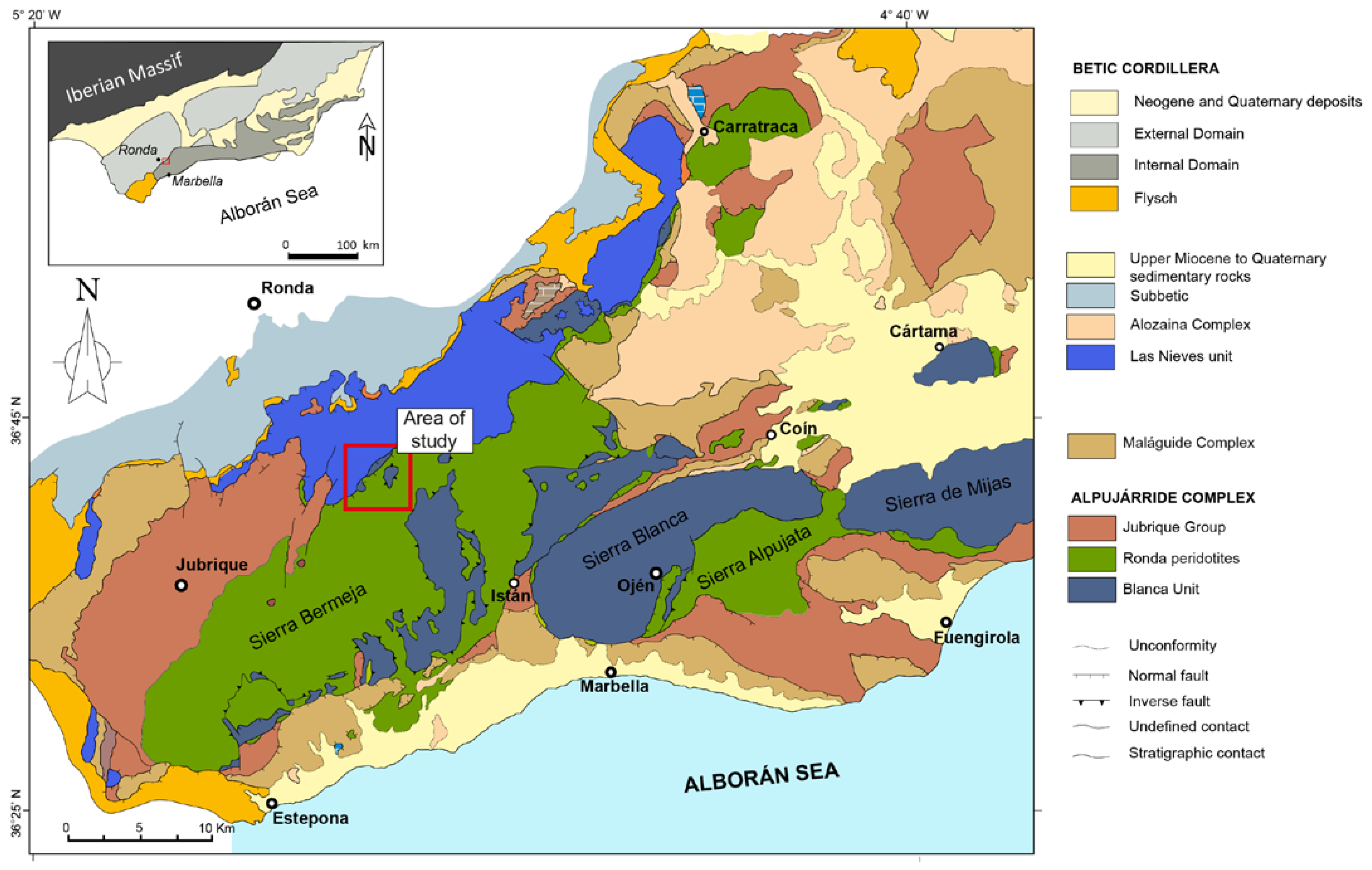
Figure 1. Geological map of the western Betic Cordillera, southern Spain showing the three main peridotite massifs cropping out in the Betic Cordillera: Ronda (~300 km2), Ojén (~70 km2), and Carratraca (~60 km2). Modified from Gervilla et al. [15]. The red rectangle marks the localization of the El Robledal area. Inset: different domains of the Betic Cordilleras.
Minerals 13 00300 g001
Figure 2. Geological sketch map of the El Robledal area: (A) simplified geological map of the northern contact of the Ronda Peridotites with the Las Nieves unit. Red lines mark the cross-section in B (B) geological cross-section of the northern contact of Ronda Peridotites and carbonates of the Las Nieves unit. Modified from Mazzoli and Algarra [51]. The red square highlights the location of the El Robledal deposit; (C) schematic column showing the structural disposition of the different zones of the El Robledal skarn. The column is rotated 90 degrees approximately with respect to the ore deposit distribution in the field, (which follows a lateral disposition) to ease the understanding of the deposit.
Minerals 13 00300 g002
Figure 3. Field images of the El Robledal deposits and host rocks. The ludwigite–magnetite zone (i.e., lud–mag) is marked with a dark-blue marked area, whereas the magnetite–szaibelyite (i.e., mag–sza) zone is marked with a light-brown area. The Ronda Peridotites are marked with a pale-green area. A fault zone separating the lud–mag zone from the serpentinized Ronda Peridotites is marked with a white-colored area. (A) Close-up view of the tectonic contact between Ronda Peridotites and the deposit; (B) panoramic view of the mining area showing the whole sequence of the deposit; (C) upper mineralized body representing the ludwigite–magnetite zone; (D) massive magnetite bands of the magnetite–szaibelyite zone, where the white arrow marks a highly deformed magnetite band; (E) detailed view of the pull-apart fractures of the magnetite bands from the magnetite–szaibelyite zone; (F) small-scale magnetite body within the dolomitic marble associated with a brucite+szaibelyite groundmass; (G) chondrodite-bearing marble with folded magnetite bands. Note that chondrodite is overall associated with magnetite bands; (H) close-up view of the massive texture of the upper body of the deposit (i.e., ludwigite–magnetite zone). Note the occurrence of trails of green-colored forsterite and late calcite veins; (I) field view of the amphibolite reaction zone limiting the skarn from the migmatites of the Blanca Unit. The dashed, red line highlights the sharp contact of the amphibolite with surrounding rocks; (J) amphibolite section obtained from the reaction zone. Lud: ludwigite; Mag: magnetite; Sza: szaibelyite.
Minerals 13 00300 g003
Figure 4. Transmitted light and reflected light microscopy photomicrographs of the El Robledal deposit. The microphotographs are arranged from the top (ludwigite–magnetite zone) to the bottom (magnetite–szaibelyite zone) of the mineralized area. (A) Massive ludwigite with interstitial forsterite. (B) Ductile deformed ludwigite crystals. (C) Cataclasized ludwigite filling fractures among granoblastic Mg-rich magnetite hosting partially serpentinized forsterite. (D) Fibrous-like, brucite-II and szaibelyite intergrowths from the magnetite–szaibelyite zone crosscut by a late serpentine vein. (E) Brucite-II and szaibelyite intergrowths around Mg-rich magnetite crystal. The dusty-brown rims around the Mg-rich magnetite are brucite-II crystals. (F) Mg-rich magnetite with brucitized cores. (G,H) Partially brucitized periclase marble in a nonmineralized area. (I) Irregular brucitized periclase bands crosscut periclase marble. The red-dashed line separates the periclase marble band from the brucite-rich band after periclase hydration. (J) Granoblastic aggregate of subhedral tremolite–actinolite grains from the reaction zone. (K,L) Porphyroclastic amphibolite with large actinolite grains partially replaced by a second generation of fibrous amphibole. Act: actinolite; Brc: brucite; Cal: calcite; Fo: forsterite; Lud: ludwigite; Mg-mag: Mg-rich magnetite; Mag: magnetite; Per: periclase; Srp: serpentine; Sza: szaibelyite.
Minerals 13 00300 g004
Figure 5. Scanned electron microscopy images showing the different textures of the El Robledal deposit ore minerals. The pictures are arranged from the top to the bottom of the deposit. Ludwigite–magnetite zone: (A) Deformed ludwigite from the upper part of the mineralized body including partially serpentinized forsterite and anhedral Mg-rich magnetite interstitial to ludwigite. (B) Granoblastic, massive ludwigite with a 120° triple junction (marked with yellow lines). (C) Euhedral Mg-rich magnetite inclusion in ludwigite. (D) A partially dissolved core of ludwigite infilled by an intergrowth of Mg-rich magnetite and fine-grained, fibrous, or flake-like hydrotalcite group minerals. (E) Mg-rich magnetite grain partially altered to magnetite along fractures. (F) Mg-rich magnetite replaced by magnetite along boundaries and fractures. Portions of magnetite are dismembered within the fracture filled with cataclasized ludwigite. (G) Partially altered Mg-rich magnetite grain embedded in a szaibelyite and brucite-II matrix. (H) Porous textures of magnetite replacing Mg-rich magnetite. (I) Euhedral Mg-rich magnetite with brucitized cores after periclase. (J) Non-fractured Mg-rich magnetite grains with unaltered periclase core. (K) Dismembered magnetite defining the borders of a pseudomorph, now replaced by szaibelyite and brucite-I, including rounded, tiny magnetite particles. (L) Kotoite relicts partially replaced by tabular szaibelyite. Magnetite–szaibelyite zone: (M) Magnetite replacing Mg-rich magnetite along fractures and boundaries including brucitized cores. Note that the grade of replacing is higher than in the ludwigite–magnetite zone. (N) Elongated and deformed Mg-rich magnetite grains with pull-apart fractures. (O) Edges of Mg-rich magnetite with brucitized cores after periclase included in a dolomite and calcite matrix. (P) Dolomite rims around Mg-rich magnetite replaced by szaibelyite and brucite-I, including rounded, tiny magnetite particles.
Minerals 13 00300 g005
Figure 6. Binary plots showing EPMA results of ludwigite: (A) MgO vs. FeOt plot showing the high Fe content of ludwigite compared with similar Mg-skarn deposits; (B) MgO vs. B2O3 plot showing the different trends of ludwigite composition in the El Robledal compared to ludwigite from other Mg-skarns deposits. The range of ludwigite composition from the El Robledal is highlighted with an orange-colored area. Data sources: (1) Ocna de Fier [14,56]; (2) Maşca Băişoara [14,54]; (3) Cacova Ierii [7,14]; (4) Pietroasa [14,54]; (5) Pitkáranta [57].
Minerals 13 00300 g006
Figure 7. Binary plots showing the oxide chemical composition: (A) MgO vs. FeOt plot of Mg-rich magnetite and magnetite showing no differences between those located in the ludwigite–magnetite zone and the magnetite–szaibelyite zone; (B) MgO vs. Al2O3 and (C) MgO vs. FeOt plots of different textured Mg-rich magnetite and magnetite.
Minerals 13 00300 g007
Figure 8. Binary plots of brucites showing the different compositions of brucite-I (red highlighted) and brucite-II (blue highlighted) in a MgO vs FeOt (A) and MgO vs B2O3 (B) diagram.
Minerals 13 00300 g008
Figure 9. Mg-number in forsterite from the El Robledal deposit compared to forsterite from the Ronda Peridotites and the San Manuel skarn. Note the extreme Mg content of the metasomatic-derived forsterite from Mg-skarns. The fields are defined based on the Fo content, according to Plechov et al. [59]. Data from González-Pérez et al. [30].
Minerals 13 00300 g009
Figure 10. (A) Backscattered electron image including the location of thin-foil (A-A’) crosscutting composite inclusion in Mg-rich magnetite from the ludwigite–magnetite zone. Sample ROB-21; (B) high-angle annular dark-field scanning transmission electron microscopy (HAADF-STEM) image of A-A’ thin foil; (C) TEM-EDS elemental map for Mg (purple), Si (yellow), and Fe (red); (D,F) HAADF images of the area corresponding to rectangles 1 and 2, respectively, marked in (C); (E) high-magnification HRTEM image at the contact of the Mg-rich magnetite and periclase marked with a white rectangle in (D); (G) SAED of the serpentine marked with a white rectangle in (F).
Minerals 13 00300 g010
Figure 11. (A) Backscattered electron image including the location of thin-foil (A-A’) crosscutting inclusions in Mg-rich magnetite from the magnetite–szaibelyite zone, Sample ROB-24; (B) high-angle annular bright-field TEM scanning transmission electron microscopy (HAABF-STEM) image of A-A’ thin foil; (C) TEM-EDS elemental maps for Mg (purple), Ca (green blue), and Fe (red); (D,G) HAADF images of the area corresponding to rectangles 1 and 2, respectively, marked in (C); (E,F) SAED of periclase and calcite marked with rectangles in (D); (H) SAED of magnetite in the area marked with a rectangle in (G).
Minerals 13 00300 g011
Figure 12. Ore microstructures from the El Robledal. The data are presented using band contrast maps (left) combined with a color-coded inverse pole figure (center), representing the crystal orientation relative to the X0, and the pole figures (right) represent the crystallographic preferred orientation relative to (001). The misorientation angles between the crystal orientation of neighboring data points were grouped into (1) low-angle boundaries, with misorientation lower than 5° (dashed, black lines), and (2) medium-angle boundaries, with misorientation of 5–10° (dashed, red lines). (A) Massive Mg-rich magnetite sample with 120° triple junctions. The IPF maps show grains with internal crystal bending (rectangles A1 to A3) that coexist with grains free of deformation. The sample shows near-random to weak patterns of CPO with numerous orientation maxima at (100), (110), and (111). (B) Granoblastic ludwigite sample with 120° curved junctions. Note the higher misorientation angles in the deformed grains compared to A (rectangles A4 to A6). This sample exhibits a strong CPO pattern, especially at (100). (C) Porphyroclastic ludwigite with elongated and deformed grains surrounding nondeformed porphyroclasts. The elongated grains show the highest misorientation degrees (rectangles A7-A8) Note the similar size of the neoblast compared to subgrains developed on deformed ludwigite porphyroclasts (rectangle A7). The pole figure shows a strong CPO pattern, especially at (100).
Minerals 13 00300 g012
Figure 13. Proposed paragenetic sequence for the El Robledal deposit.
Minerals 13 00300 g013
Figure 14. A proposed genetic model for the El Robledal deposit formation. Red arrows represent the percolating mineralizing fluids released from migmatite. (A) Metamorphic stage. The heat provided by the ultramafic rocks promoted dolomite decomposition and periclase formation. Fluids/melts emanating from incipient anatexis should not have interacted with the dolomites of the Blanca unit during this stage. (B) Prograde stage. The interaction of mineralizing fluids emanating from migmatites and dolomite of the Blanca unit led to olivine and Mg-rich magnetite formation. (C) Further fluid/rock interaction promoted kotoite and ludwigite formation in the outermost part of the skarn. (D) Retrograde stage. The decreasing temperature of the mineralized fluids led to primary borate alteration into szaibelyite and B-bearing brucite. Such a process is widespread close to the fluid source (i.e., migmatites) where the fluid/rock ratio is expected to be higher than in the zone close to the ultramafic rocks. (E) Late retrograde stage. The former reactions promote an increase of CO2 and thus enhanced hydrous-carbonate formation. In zones of fractures, the excess of CO2 should have been channelized generating hydrous Mg-carbonates and calcite veins.
Minerals 13 00300 g014
Disclaimer/Publisher’s Note: The statements, opinions and data contained in all publications are solely those of the individual author(s) and contributor(s) and not of MDPI and/or the editor(s). MDPI and/or the editor(s) disclaim responsibility for any injury to people or property resulting from any ideas, methods, instructions or products referred to in the content.