Article

The Origin of Synchysite-(Ce) and Sources of Rare Earth Elements in the Rožná Uranium Deposit, Czech Republic

1
Czech Geological Survey, Geologická 6, 152 00 Prague, Czech Republic
2
Faculty of Sciences, Masaryk University, Kotlářská 267, 611 37 Brno, Czech Republic
3
Institute of Geochemistry, Mineralogy and Mineral Resources, Faculty of Science, Charles University, Albertov 6, 128 43 Prague, Czech Republic
*
Author to whom correspondence should be addressed.
Minerals 2022, 12(6), 690; https://doi.org/10.3390/min12060690
Submission received: 4 May 2022 / Revised: 23 May 2022 / Accepted: 23 May 2022 / Published: 29 May 2022
(This article belongs to the Section Mineral Deposits)

Abstract

:
Synchysite was identified in the Rožná uranium deposit in a quartz–carbonate–sulfide vein, which is a part of the late (post-uranium and, post-Variscan) stage of the development of the hydrothermal system. The synchysite forms needles or lamellae, which are almost exclusively bound to the quartz filling of the veins. The structure of the quartz vein-filling, i.e., the preserved tubular syneresis crack pattern, Liesegang bands formed by hematite, chaotic grain size distribution of quartz grains, and ribbons of fibrous SiO2 grains, indicate that the synchysite crystallized in a silica gel. Its formation may be explained by the reaction of hydrothermal acid fluids rich in Fe2+ and rare earth elements (REEs) with alkaline Ca2+ HCO3 and F-rich fluids expelled from the gel during syneresis, or by its ageing. The subsequent recrystallization of the gel to form euhedral quartz grains was accompanied by the deformation of previously formed Liesegang rings, and the development of quartz rosettes. The study of fluid inclusions indicated that the silica gel originated at a very low temperature. The temperatures of the homogenization of two-phase inclusions in carbonate and quartz vein-filling varied between 38 and 74 °C, and the salinity ranged between 4 and 10 wt.% NaCl equiv. The δ13C carbonate values (from −4.65 to −5.21‰, PDB) indicate the deep-seated source of CO2, and δ18O values (from 14.76 to 18.22‰, SMOW) show that the source of the hydrothermal fluids was mainly surface water, with a possible admixture of fossil saline brines. The main sources of REEs are thought to have predominantly been uranium minerals (coffinitized uraninite and coffinite) that form a part of the breccia fragments embedded in the vein filling. The results illustrate the significant mobility of REEs in the late, low-temperature hydrothermal system, and they indicate the multiple remobilizations of REEs in the uranium deposits in general.

1. Introduction

At present, rare earth elements (REEs), such as lanthanoids and yttrium, belong to the class of so-called critical materials (CRMs) [1], without which it would be impossible to guarantee the development of high technologies and the manufacturing of high-tech products. REE deposits are mostly associated with carbonatites or alkaline/peralkaline igneous rocks, the formation of which is linked to the extension/transtension structures of old shields. The Bayan Obo hydrothermal deposit in Inner Mongolia, China (which is bound to carbonatites [2,3,4,5]), may serve as a typical example. A review of other REEs deposits associated with carbonatites or alkaline magmatic rocks was conducted by Elliot et al. [6]. However, due to uncertainty about the availability of REE raw materials and the development of their price in the future [7,8], there is a growing interest in the possibility of obtaining REEs from other types of deposits that are not directly associated with carbonatite–syenite complexes or alkaline magmatism. These include iron oxide copper gold (IOCG) and uranium deposits. The Olympic Dam appears to be the best example, showing significant REE enrichment in the iron oxide copper-gold (IOCG) deposit [9]. The local breccias of this deposit contain from 3000 to 5000 ppm of lanthanoid oxides and Y oxide [10], and the major REE minerals include allanite, monazite, bastnäsite, florencite and synchysite. REE concentrations in these breccias positively correlate with hematite contents in host rocks, indicating oxidation conditions during the formation of REE minerals [11].
In addition to IOCG deposits, numerous unconformity-related U deposits of the Athabasca Basin in Canada (Key Lake, Cigar Lake, and Mc Arthur Lake) also contain relatively high concentrations of REEs. Uranium minerals in these deposits contain up to 1.2 wt.% REE [12], with heavy rare earth elements (HREEs) predominating. The highest concentrations of REEs in uranium minerals occur along the late oxidation–reduction boundary, indicating their remobilization during low-temperature processes [13]. In the past, REEs were extracted as a by-product during the mining and processing of uranium-bearing quartz conglomerates in the Blind River–Elliot Lake mining district in Ontario, Canada [14]. Mining resources in the Eco Ridge deposit, located in the same area, have been estimated to be as much as 14.3 million tons at an average concentration of 0.48 wt.% U and 0.164 wt.% REE oxides [15]. A close relationship between uranium mineralization and elevated REE concentrations is also known from the Mary Kathleen skarn deposit in Queensland, Australia [16]. The breccia zone of this deposit contains 3000–5000 ppm of REE oxides, and the central hematite–quartz zone is even richer [10]. Bastnäsite, florencite and synchysite are the main REE-bearing minerals.
In the Rožná uranium deposit, which is the subject of this study, REEs are mainly bound to uranium minerals (uraninite, coffinite, and minor brannerite) [17]. However, as a part of the evaluation of the possibility of extracting REEs as a by-product of ore mining and mineral processing [18], high concentrations of REEs were also found in a quartz–carbonate–sulfide vein, which is much younger than the uranium mineralization. These high REE concentrations are due to the occurrence of synchysite, which is very abundant in the quartz filling of the vein. The objective of this work was to clarify the origin of the synchysite and to elucidate the possible sources of REEs in the final stage of the evolution of the hydrothermal system in Rožná.

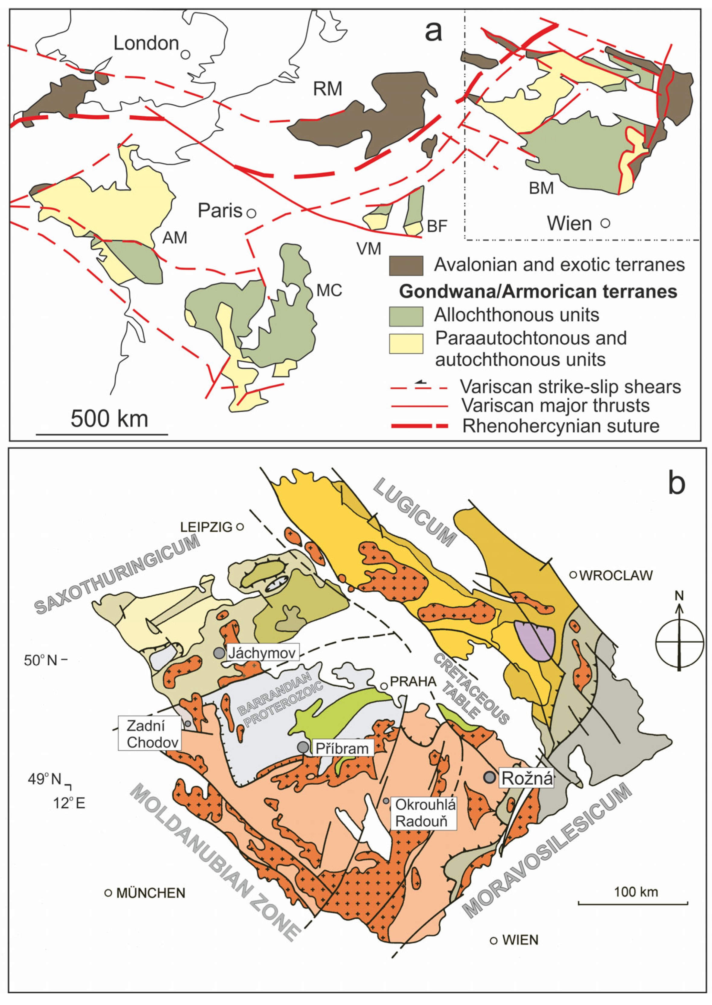
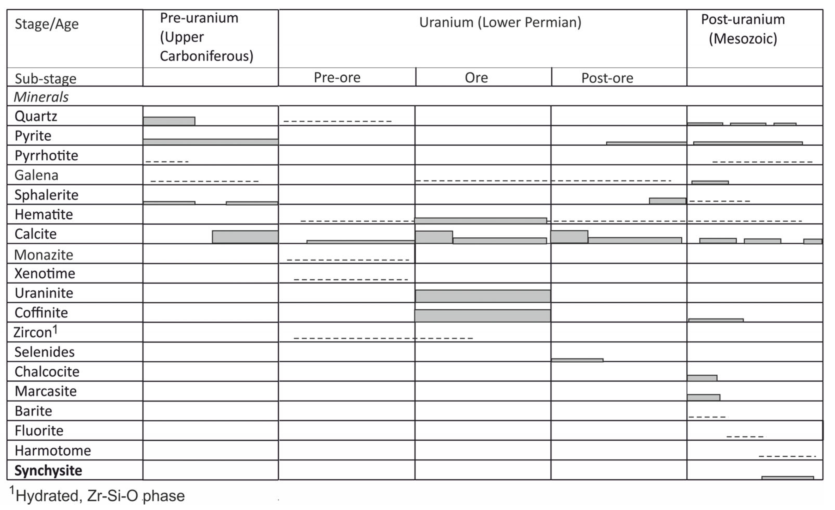
2. Geological Setting and Uranium Mineralization in the Rožná Deposit

The Bohemian Massif is an important uranium province in the European Variscan belt (Figure 1a [19]). A cumulative total of 112,153 metric tons U was produced in the Czech Republic during the period of 1946–2018 [20]. The uranium deposits of the Bohemian Massif include both the vein-type deposits (Příbram: total production of 50,000 t U; Jáchymov: total production of 8500 t U) and shear-zone hosted deposits of the disseminated-type (Zadní Chodov: cumulative production of 4200 t U; Okrouhlá Radouň: cumulative production of 1300 t U; and Rožná: cumulative production of 23,000 t U (Figure 1b)) [17].
Uranium mineralization in the Rožná deposit is bound to the system of faults and zones of cataclasites of the NNW–SSE strike in high-grade metamorphic rocks of the Moldanubian Zone of the Bohemian Massif. Mineralized cataclasites are 4–15 m thick and are traceable over a horizontal distance of 15 km. The zones strike 340–355° and dip west at an angle of 45–70° [21]. The host rocks of the Rožná deposit mainly comprise biotite, plagioclase, K-feldspar, quartz, garnet, sillimanite, hornblende gneiss, and amphibolite, with small bodies of calc-silicate gneiss, marble, serpentinite, and pyroxenite. Biotite and amphibole–biotite gneisses show ample evidence of anatexis. Vein and disseminated mineralization at Rožná comprise (1) pre-uranium quartz–sulfide and carbonate sulfide mineralization, (2) uranium, and (3) post-uranium carbonate–quartz–sulfide mineralization (Figure 2).
The pre-uranium mineralization (from 304.5 ± 5.8 to 307.6 ± 6.0 Ma K–Ar ages for sericite [21]) coincided with the post-orogenic exhumation of the Moldanubian orogenic root and retrograde-metamorphic equilibration of the high-grade metamorphic host rocks. The main uraniferous hydrothermal event (from 280 to 260 Ma U-Pb ages) [22] coincided with the transcurrent reorganization of crustal blocks of the Bohemian Massif and with Upper Stephanian to Lower Permian rifting. The massive hematitization, albitization, and desilicification of the host rocks indicate an influx of oxidized basinal fluids into the crystalline rocks of the Moldanubian zone. Based on a fluid-inclusion study and chlorite thermometry, the temperature of the formation of uranium mineralization has been estimated to be between 150 and 200 °C. The wide range of salinities of fluid inclusions is interpreted to be a result of the large-scale mixing of basinal brines with meteoric water [23,24]. The uranium mineralization event is subdivided into the pre-ore, ore, and post-ore substages (Figure 2). Uranium mineralization formed during the main ore-bearing substage and comprises uraninite, coffinite, and more complex U-Ti-Si-Zr mineral phases [17].
Figure 2. Stages, substages and types of late Variscan and post-Variscan hydrothermal mineralization in the Rožná uranium deposit. Simplified following [21,24].
Minerals 12 00690 g002
The age of the youngest post-uranium quartz–carbonate–sulfide mineralization (from 233.7 ± 4.7 to 227.5 ± 4.6 Ma K–Ar ages on sericite) is consistent with the early Tethys-Central Atlantic rifting and tectonic reactivation of the Variscan structures of the Bohemian Massif. A minor part of the late Variscan uranium mineralization was remobilized during this hydrothermal event. The results of the fluid inclusion studies on this type of mineralization indicate the low-temperature (from 178 to less than 100 °C [23,24]) mixing of several types of fluids including meteoritic water, with highly variable physical and chemical conditions during the formation this type of mineralization [25].

3. Materials and Methods

Samples of the synchysite-bearing quartz–carbonate–sulfide vein and host rocks were collected on the 20th floor of the Rožná deposit. The individual samples (n = 15) were crushed and pulverized in an agate mill to a size of <0.063 mm. Whole-rock analyses (major components) were performed by chemical decomposition using a standard methodology applied in the accredited laboratories of the Czech Geological Survey [26]. Whole-rock samples for REE analysis were fused in a mixture of Li2B4O7 and Na2CO3, transferred into an HNO3 solution, and analyzed with the inductively coupled plasma mass spectrometry (ICP-MS) method in an Agilent Technologies 7900 mass spectrometer in the laboratories of the Czech Geological Survey. Other trace element concentrations were determined using ICP-MS at the Bureau Veritas Mineral Laboratories Ltd. (Vancouver, Canada; former Acme Analytical Laboratories), accredited under ISO 9002. Material (0.25 g) was heated in an HNO3-HClO4-HF solution until it began to produce fumes, and then it was dried. The residues were dissolved in a 3% HNO3 solution and analyzed using ICP-MS. A total of 5% of the samples were re-analyzed as control samples. The relative percent differences (RPDs), calculated using the certified reference materials CRM OREAS 25a and OREAS 45e, were less than ±10% of the certified values for the analyzed elements. Thin and polished sections of the quartz–carbonate–sulfide vein and host rocks (n = 20) were studied with a polarizing microscope in transmitted and reflected light.
The chemical compositions of the minerals (synchysite, titanite, coffinitized uraninite, and coffinite) were determined with wavelength dispersive X-ray spectroscopy (WDS) using a Cameca SX100 Electron Probe Micro Analyzer (EPMA) CAMOR, University of Oregon, U.S.A. An accelerating voltage of 15 kV, a beam current of 10 nA, and a defocused electron beam with a circular spot of 10 µm in diameter were applied for the analysis. For synchysite analyses, the following natural and synthetic materials were used for calibration: F Kα PrF3, Si-Kα sanidine, Ca-Kα fluorapatite, Y-Lα YPO4, La-Lα LaPO4, Ce-Lα CePO4, Dy-Lα DyPO4, Tb-Lα TbPO4, Tb-Lα TbPO4, Pr-Lβ PrPO4, Nd-Lβ NdPO4, Sm-Lβ SmPO4, Eu-Lβ EuPO4, and Gd-Lβ GdPO4. Prior to the analysis, extended wavelength scans were performed to avoid any peak overlap. Raw X-ray intensities were corrected for matrix effects with a φρ(z) algorithm of the X-PHI routine [27], and the theoretical CO2 content was included in the matrix-correction procedure. An empirically determined correction factor was applied to the coincidence of the 2nd-order of Ce-Mz with the F-Ka line, Dy- with the Eu-Lβ line, and Er- with the Tb-Lβ1_4 line. Other elements with Z > 9 were sought, but their concentrations were below the detection limit. The empirical formulae were calculated based on ΣREE = 3 atoms per formula unit (apfu). The amount of OH was charge-balanced. The determined Si content was not included in the charge balance. A total of ten samples of synchysite were analyzed. The mutual textural relationships between the minerals were studied using a TESCAN MIRA, TESCAN 3 scanning electron microscope (SEM)(TESCAN, Brno, Czech Republic), which was equipped with two Oxford Instrument ULTIM-MAX 100 EDS detectors (Thermo Fisher Scientific Inc., Waltham, Massachusetts, U.S.A.). The voltage used was 15 kV, and the absolute current was 3 nA. The instrument was calibrated to SPI standards.
Powder X-ray diffraction (PXRD) was employed within the phase analysis of the samples. Data were collected using Bragg–Brentano geometry on a Bruker D8 Advance diffractometer (Bruker, Delaware, U.S.A.) equipped with a silicon-strip linear LynxEye detector and Soller slits (2.5°). CuKα radiation was used.
A qualitative phase analysis was performed using the DIFFRAC.EVA [28] software and the PDF-2 database. Calculations of the unit-cell parameters were made by means of the Rietveld method using the TOPAS 5 program [29]. Altogether, four samples of coffinitized uraninite and coffinite were analyzed. The results were analyzed and interpretated by František Laufek from the Czech Geological Survey.
To obtain Raman spectra, a sample of synchysite was placed on the stage of Leica microscope, equipped with 5×, 20×, 50×, and 100× objective lenses. The microscope was part of a multichannel Renishaw InVia Reflex spectrometer (Renishaw, Brno, Czech Republic) coupled with a thermoelectrically cooled CCD detector. Excitation was provided by a 514.5 nm Ar laser (power: ~20 mW at source). To achieve enhanced signal-to-noise ratios of the Raman signal, 30 scans were accumulated, each for a 20 s exposure time. Spectra were recorded within a 100–2000 cm−1 spectral wavenumber range with an operational spectral resolution of 2 cm−1. A polystyrene standard was used to verify the internal wavenumber calibration. Spectral analyses and treatments, such as baseline correction, were performed using the GRAMS/AI 9.1 software package (Thermo Fisher Scientific, Waltham, Massachuses, U.S.A.).
Fluid inclusions were studied in both-sided polished sections of a 0.3 mm thickness via methods of optical microthermometry by LINKAM THMS600 temperature controlled stage (Linkam Scientific Instruments Ltd., Surrey, United Kingdom) on an Olympus microscope (Olympus, Japan). The equipment was calibrated for temperatures between −100 and +400 °C by chemical standards from the Merck Company, the temperature of ice melting, and phase transitions in inclusions with pure CO2. Homogenization and cryometric data indicate a reproducibility of ±0.2 °C at temperatures below 0 °C and a reproducibility of ±3 °C at temperatures up to 400 °C. The salinity of the water solutions was recalculated according to the work of Bodnar and Vityk [30], and the composition of salt systems was determined according to the work of Davis et al. [31].
The fluid inclusions were assessed at room temperature from the viewpoint of individual populations, i.e., fluid inclusion assemblage [32]. The relationship to the host mineral (primary, pseudosecondary, or secondary inclusions), the shape and size of inclusions and the degree of filling, i.e., liquid-to-vapor ratio, were also determined. Phase changes in the inclusions were detected with measurements of the following temperatures:
Th—bulk temperature of homogenization.
Te—temperature of the first melting (eutectic temperature).
Tm—temperature of melting of the last ice crystal (calculation of salinity).
For stable isotope studies, samples of vein carbonates were gently spread in an agate bowl and decomposed in 100% phosphoric (V) acid in a vacuum at 25 °C overnight [33]. The composition of isotopes δ13C (‰) and δ18O (‰) in the released CO2 was measured with a Delta V mass spectrometer in laboratories of the Czech Geological Survey. The total error of isotopic composition determination was ±0.1 ‰. The isotopic composition of carbon is related to the Pee Dee Belemnite (PDB) international standard. The values of the oxygen isotopic composition related to the Vienna Standard Mean Ocean Water (SMOW) standard were determined from the values measured against the PDB standard by recalculation. The isotope composition of oxygen and carbon in calcites I and II was recalculated to the isotopic composition of oxygen and carbon in the fluid phase [34].

4. Results

4.1. Petrography and Mineralogy of the Synchysite-Bearing Vein and Host Rocks

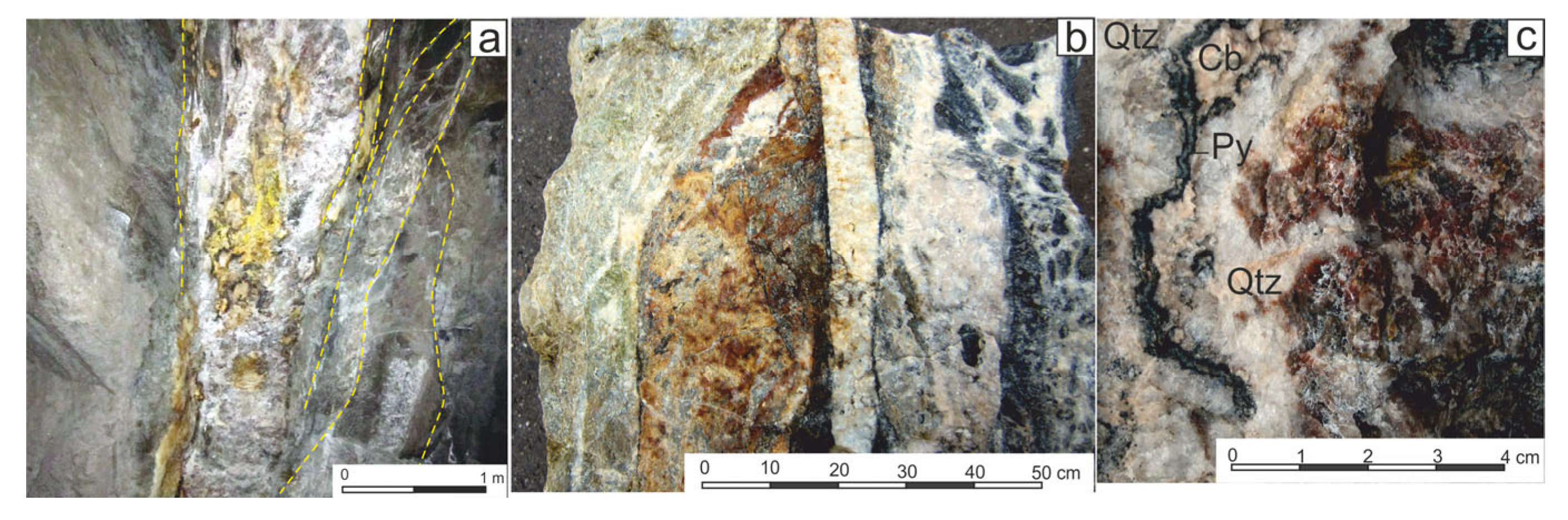
4.1.1. The Synchysite-Bearing Vein

The quartz–carbonate–sulfide vein with synchysite was found to consist of several generations of calcite and quartz. The vein is rimmed from both sides by a series of small fold lines arranged in an en echellon. In marginal parts, the vein very often shows a breccia-like structure and encloses fragments of the host rocks (Figure 3a,b). Due to the variable contents of hematite and sulfides (pyrite and marcasite), the quartz–carbonate vein filling was found to exhibit reddish or gray color shades. Sulfides are either dispersed in the vein filling or form up to 5 mm thick rims along the boundary of the predominantly carbonate, as well as quartz, sections of the vein (Figure 3c).
The vein encloses many fragments of older uranium mineralization, as is evident from the green–yellow coatings on the surface of the rock fragments, formed from a mixture of jarosite and secondary uranium minerals (Figure 3a). In thin sections, the mineralized clasts embedded in the vein filling were found to be composed of uranium minerals (coffinitized uraninite and coffinite), pyrite, and carbonates in the chloritized and graphitized host gneiss (Figure 4a). The irregularly shaped accumulations of coffinite cemented by carbonates show ample evidence of their dissolution (Figure 4b). The chemical composition of coffinitized uraninite and coffinite was found to be very variable (Table S1). The content of SiO2 was found to range from 7.85 wt.% to 22.7 wt.% in the coffinitized uraninite, and the coffinite contents of ZrO2 and TiO2 were found to be relatively low in coffinitized uraninite but reached up to 4.1 wt.% and 19.2 wt.%, respectively, in coffinite.
Lead (0.18–2.32 wt.% PbO) is probably bound to finely dispersed radiogenic galena in both minerals, and the CaO content was found to range from 1.31 to 3.86 wt.%. Coffinitized uraninite and coffinite were shown to predominantly contain light rare earth elements (LREEs) (Ce2O3: up to 1.43 wt.%; Nd2O3: up to 0.25 wt.%; and Sm2O3: up to 0.21 wt.%), whereas the contents of heavy rare earth elements (HREEs) were lower, and Y2O3 was detected only in two of the samples (0.12 and 0.29 wt.%). The contents of other REEs were lower than the EMPA detection limit.

4.1.2. Host Rocks

The host rocks were revealed to be chloritized, argillized, and albitized fine-grained biotite–hornblende gneisses with carbonate veinlets and a varying amount of carbonaceous substances. Uranium minerals in the host gneiss usually replace corroded remnants of older pyrite or occur along the cleavage planes in biotite or chloritized biotite. A common accessory in altered rock is titanite. In addition to TiO2 (from 35.1 to 37.2 wt.%), SiO2 (from 30.0 to 30.5 wt.%), CaO (26.2–28.5 wt.%), and F (from 0.35 to 0.49 wt.%), unaltered titanite was found to contain from 0.15 to 0.36 wt.% Ce2O3, from 0.11 to 2.64 wt.% Y2O3, and small amounts of Nd2O5, Gd2O3, and Dy2O3 (Table S2). Titanite in host rocks is usually, to variable degrees, hydrothermally altered to a mixture of anatase (verified by Raman spectroscopy), quartz, and carbonate (Figure 5a). REEs are released from a titanite structure during hydrothermal alteration to form small grains of monazite and xenotime attached to the anatase grains (Figure 5b). Other accessories recorded in altered host rocks include corroded grains of fluorapatite (Figure 5a) and small oval grains of zircon, usually hosted in chloritized biotite.

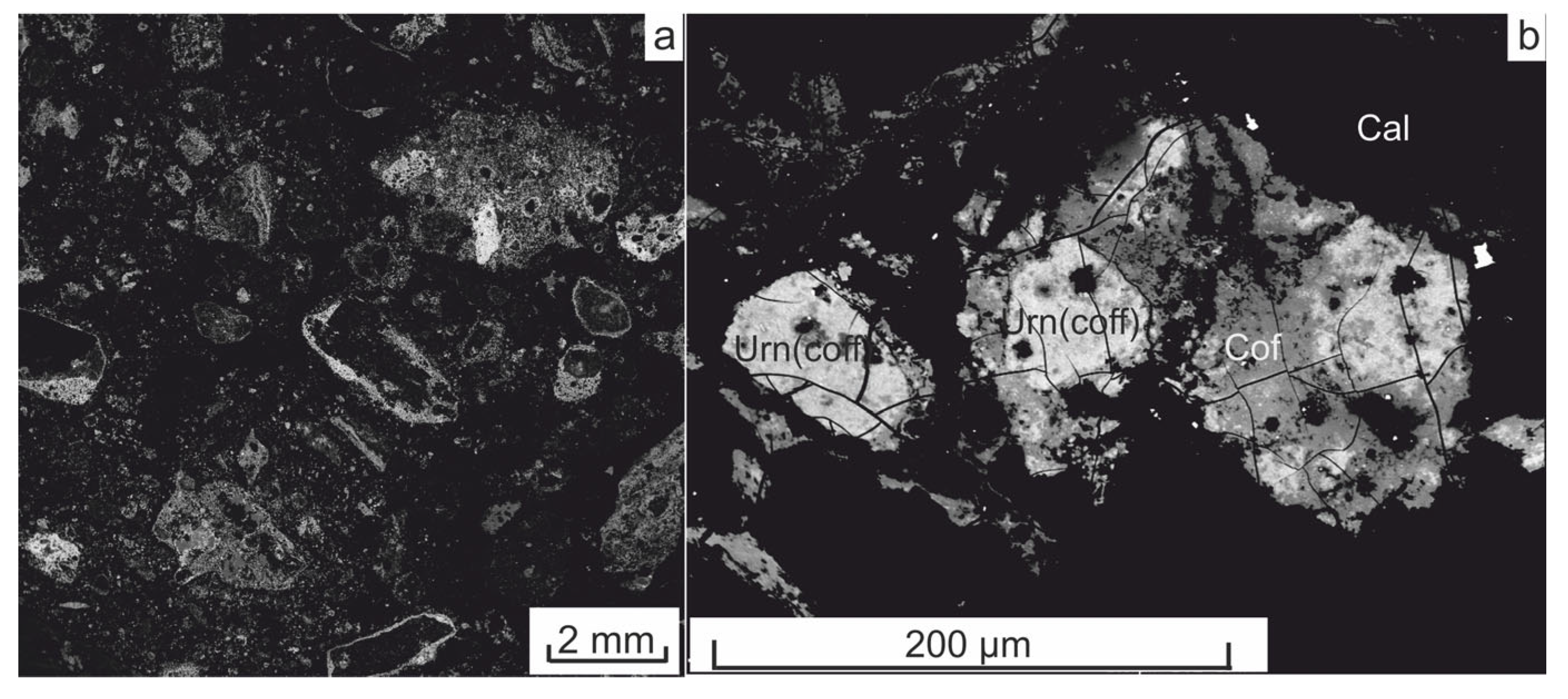
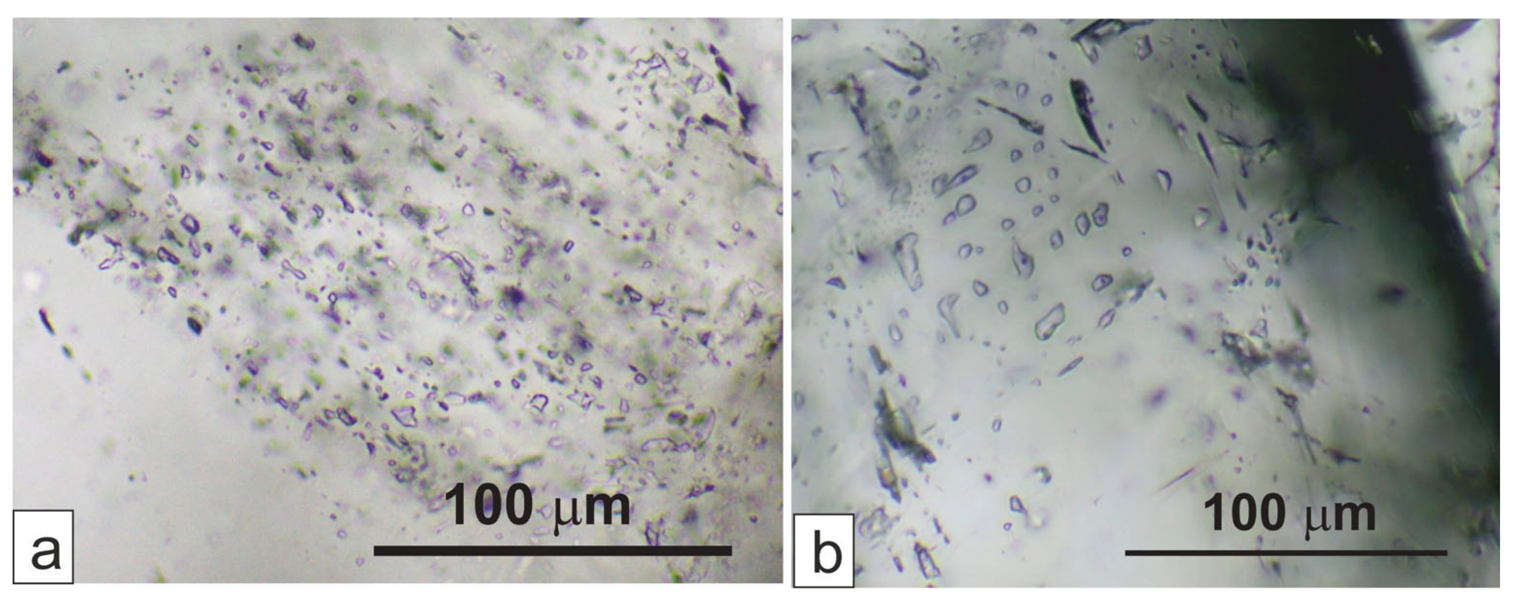
4.2. Textures of Synchysite-Bearing Quartz Filling of the Vein

Synchysite was found to be exclusively bound to the quartz filling of the vein. The texture of quartz filling was shown to be very heterogeneous, resembling the internal fabric of some types of agate or jasper (Figure 6a). Quartz was shown to occur as either (1) more or less equant or elongate grains up to 2 mm in size, and in many sections of the vein, it was found to form rosettes (Figure 6b) or (2) poorly demarcated aggregates of fine (a few μm large) grains, usually in association with sub-microscopic grains of clay minerals, carbonate, and hematite. Some fine-grained quartz aggregates showed a fibrous internal fabric resembling chalcedony (Figure 6c).
Typical features of the quartz vein filling were found to be numerous, wormy, tubular, contorted or linear structures (Figure 6d), the central parts of which were shown to usually comprise hematite with variable admixtures of fine-grained quartz and carbonate (Figure 6e,f). These structures are usually rimmed by multiple bands of hematite pigment. Most needle-or plate-shaped synchysite crystals grow on the outer edges of these hematite bands (Figure 6g,h). The formation of the hematite bands preceded the recrystallization of the original quartz vein filling, as is indicated by their deformations during the growth of the quartz grains (Figure 6i). During the crystallization of quartz, the calcite grains were enclosed between the quartz grains (Figure 6k), and the quartz vein filling was found to be penetrated by tiny veinlets of younger calcite (Figure 6k). Corroded clasts of light brown sphalerite a few millimeters in size are obviously older than the vein quartz filling itself (Figure 6l). The textural features of the quartz vein filling—especially the bands comprising hematite and exhibiting wormy, tubular, contorted or linear structures—suggest that the synchysite originated in a silica gel that later recrystallized.

4.3. Chemical Composition of Quartz–Carbonate–Sulfide Vein and Host Rocks (Whole Rock Analyses)

The great variability in the chemical composition of the quartz–carbonate–sulfide vein is mainly due to the varying proportions of quartz and calcite. This is especially reflected in the concentrations of SiO2, CaO, and CO2 (Table 1) in the individual samples. However, the concentrations of other major elements in the predominantly quartz or mostly calcite vein gangue were not found to significantly differ from each another (Table 1). Of the trace elements, the quartz–carbonate–sulfide vein was found to contain high concentrations of U (307–676 ppm) and Pb (473–2157 ppm), which suggests that the studied vein contains fragments of older uranium mineralization. Among the uranium minerals, coffinitized uraninite, coffinite, and unspecified uranium carbonates were identified using a microprobe. Concentrations of As (36–1021 ppm) and Mo (29–153 ppm), i.e., elements that accompany the uranium mineralization in the Rožná deposit [25], were also shown to be high. Very high contents of Zn (654–8014 ppm) correspond to the frequent occurrence of sphalerite blebs in the quartz-rich part of the vein (Figure 6l). It was shown that sphalerite in the Rožná deposit very often occurs in association with barite in the post-ore stage of mineralization, which corresponds to the relatively elevated concentrations of Ba (64–233 ppm).
The host rocks were found to comprise strongly chloritized, argillized and hematized gneisses. Aluminum, Ti, and possibly some Fe are likely to be bound to feldspars, biotite and chlorite. Some of the Fe may also be bound to pyrite or marcasite. However, the amount of iron bound to the sulfides was shown to be rather small because of the low content of total sulfur in altered gneisses (Stot = 0.01–1.14 wt.%). In samples H1–H4 (Table 1), Na2O (4.75–10.6 wt.%) strongly was found to prevail over K2O (0.13–1.12 wt.%), which indicates a significant albitization of neighboring gneisses.
The processes of albitization and the formation of Na-metasomatites have been described in the Rožná deposit [17,24]. An exception is sample H5 (a slightly chloritized biotite gneiss), which was taken 4 m from the vein structure and in which the Na2O/K2O ratio was shown to be reversed; it is a slightly chloritized biotite gneiss (Table 1). Of the trace elements, the contents of As, Pb, Zn, Th, and U were found to be significantly lower in the host rocks than in the synchysite-bearing vein, which indicates that they are less mineralized or even impoverished in these elements, while the contents of Co, Cr, Cu, Ni, V, and Zr were higher, probably due the occurrence of mafic minerals and zircon.
The contents of REEs in the samples (whole rock data) were normalized to C-3 chondrite [35], and the REE abundance patterns were classified based on the chondrite-normalized elemental ratios. The europium anomaly (Eu/Eu*) was calculated as EuN/(SmN × GdN)0.5 and the Ce anomaly (Ce/Ce*) was calculated as CeN/(LaN × PrN)0.5, where the subscript indicates chondrite normalization. The tetrad effects were calculated according to [36]. The ΣREE content in the vein gangue was found to range between 680 and 4366 ppm, and the spectrum of REE was shown to be dominated by Ce (260–1781 ppm), La (142–1032 ppm), and Nd (141–862 ppm). The content of Y was shown to vary between 41 and 175 ppm (Figure 3 and Table 2). The content of ΣREE decreases from the quartz-dominated to carbonate-rich parts of the vein. The chondrite-normalized patterns are very steep, and the LREE⁄HREE ratio (expressed as LaN/YbN) in the vein gangue ranges between 30 and 259. All the samples were found to only display very weak negative europium (Eu/Eu* = 0.71–0.87) and cerium anomalies (Ce/Ce* = 0.83–0.90). The calculated values of the tetrad effect in the vein gangue were shown to be low (T1/3 = 0.93–0.95). Generally, the chondrite-normalized patterns of the vein gangue were observed to be very similar to the synchysite chondrite-normalized patterns (see below). The ΣREE content in the host rocks (165–221 ppm) was found to be lower and uniform compared to the vein gangue, and the chondrite-normalized REE patterns was shown to be flatter (LaN/YbN = 6.4–9.4). The Eu/Eu* ratio (0.76–1), the Ce/Ce* ratio (0.971–1), and the tetrad effect (T1/3 = 0.97–1.03) were observed to be very weak or not observed at all (Figure 7 and Table 2). The chondrite-normalized REE pattern of synchysite-bearing vein displayed slightly more negative Ce anomalies (Table 2) compared to the altered host rocks (0.83–0.90; Table 2). Under oxidizing conditions, Ce3+ is transformed into the less mobile Ce4+ state. Therefore, the more negative Ce anomalies in the synchysite-bearing vein may have been caused by the higher oxygen fugacities of the fluids during vein formation compared to the fluids which affected the host rocks during the older uranium stage of the mineralization.

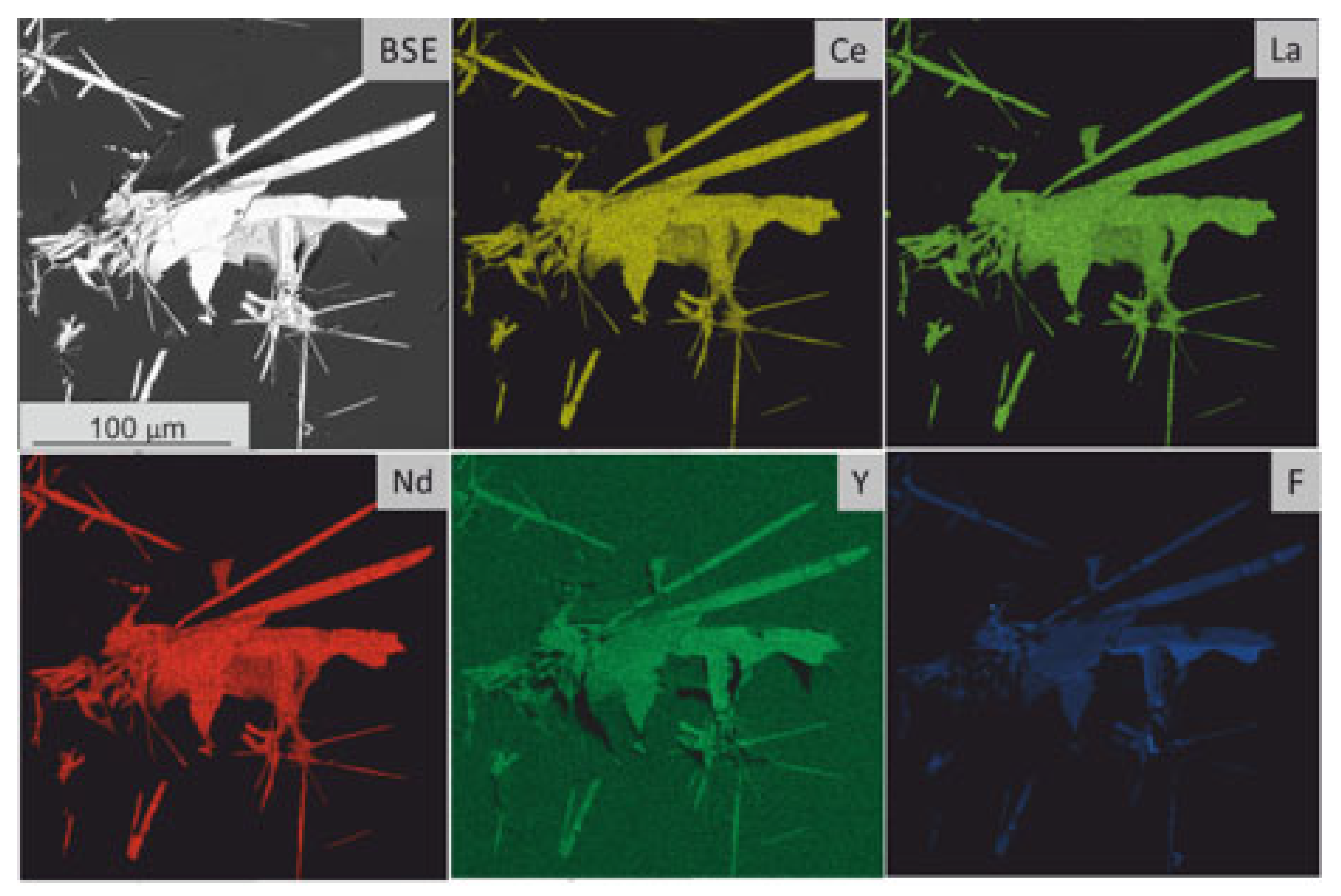
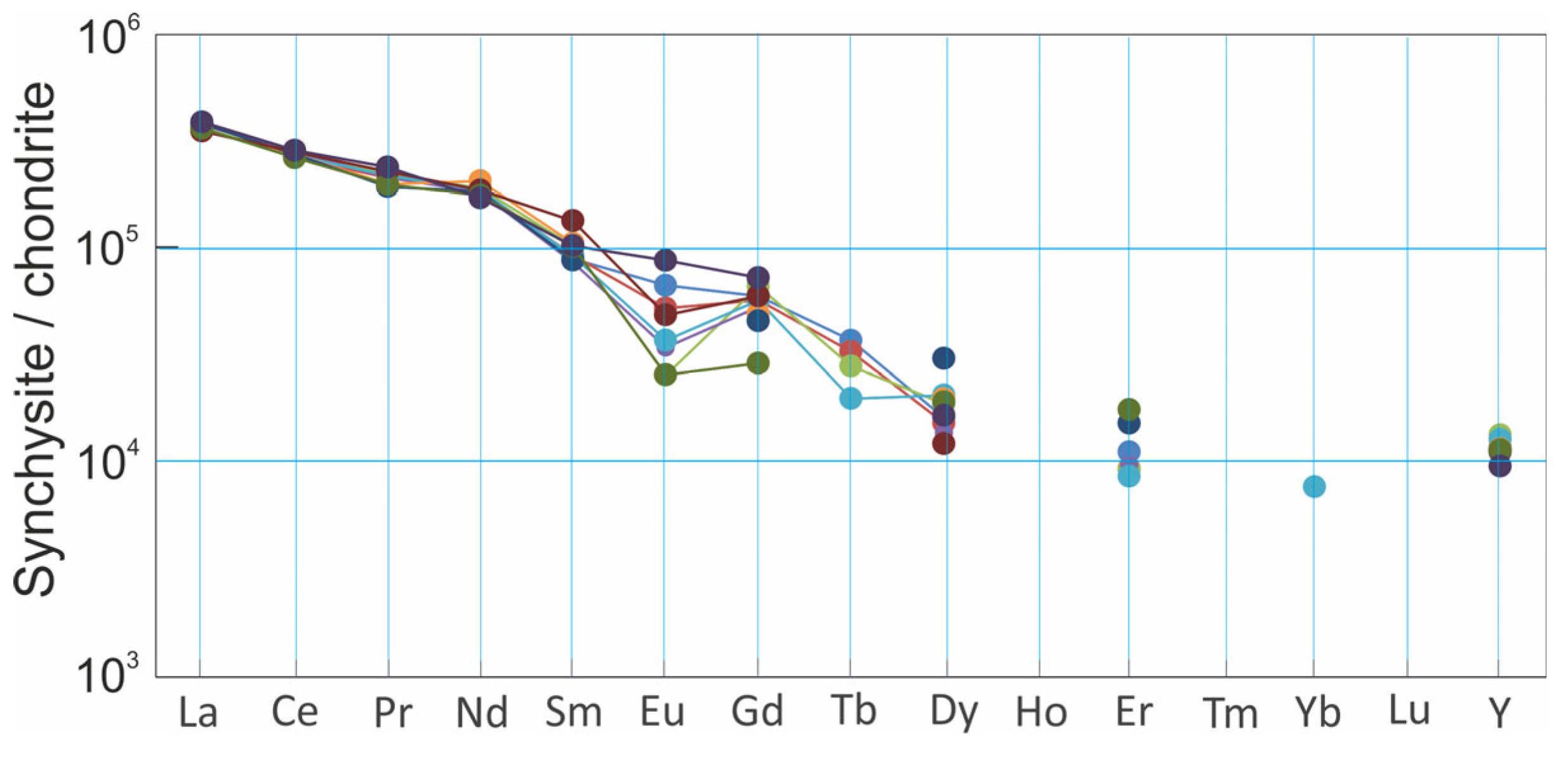
4.4. Synchysite Raman Spectrum and Chemistry

The Raman spectrum of the synchysite in the quartz gangue of the studied quartz–carbonate–sulfide vein in Rožná was found to display a number of Raman bands. The strongest Raman features were found at 1081 and 1099 cm−1, and these represent the ν1 symmetric stretching mode of the (CO3) group (Figure 8). In contrast to most carbonates, which usually have one v1 band, the splitting of bands observable in this region typically implies at least two distinct site symmetries for the (CO3) groups [37,38]. A broad band around 1454 cm−1 and a weak band at 1416 cm−1 were caused by the ν3 asymmetric stretching mode of (CO3). Other bands that may be obviously assigned to the carbonate group were found at 741 and 756 cm−1, which are associated with the ν4 in-plane bending mode of (CO3). Numerous bands were observed below 600 cm−1 at 254, 277, 299, 355, and 393 cm−1. These can be best-described as lattice modes, although Raman bands of any internal modes involving a fluorine atom would also be detected in this spectral region for halogen-containing carbonates [39]. Altogether, the Raman spectrum of synchysite studied in the Rožná deposit can be compared with the spectrum of synchysite-(Ce) reported by Alles et al. [40].
Furthermore, the spectrum contains a number of additional bands. The band at 464 cm−1 could be undoubtedly ascribed to quartz. Other weak bands in the spectrum (indexed by r) are signatures of a synthetic resin from a thin section. Synchysite-(Ce) was also confirmed by PXRD (data not shown). The studied synchysite was found to be very chemically homogeneous, and intergrowths with other REE fluorocarbonates were not observed (Figure 9).
The ΣREE contents of synchysite were found to be very homogeneous (41.8–43.3 wt.% EMPA; Table 3), and the spectra were found to be dominated by LREE (0.60–0.66 apfu of La, 1.18–1.24 apfu of Ce, 0.13–0.16 apfu of Pr, and 0.53–0.65 apfu of Nd). The HREE contents were lower (0.085–0.132 apfu of Sm, 0.04–0.09 apfu of Gd, ≤0.09 apfu of Tb, 0.02–0.05 apfu of Dy, ≤0. 02 apfu of Er, and ≤0.007 apfu of Yb). The content of Y was found to range from 0.017 to 0.23 apfu. The C3-chondrite-normalized pattern (Figure 10) was shown to be very steep, and the LREE⁄HREE ratio was found to range between 47.5 and 136.5 (LaN/YbN) and 21.2–73.4 (PrN/ErN). Synchysite samples displayed negative or no Eu anomalies (EuN/EuN* = 0.309–1.015). The first tetrad effect (t1) was shown to be very weak (0.86 to 1.01), and no cerium anomalies were recorded. Generally, the chondrite-normalized pattern of the analyzed synchysite was similar to the whole-rock REE patterns of the quartz-dominated part of the vein filling (see Figure 7).

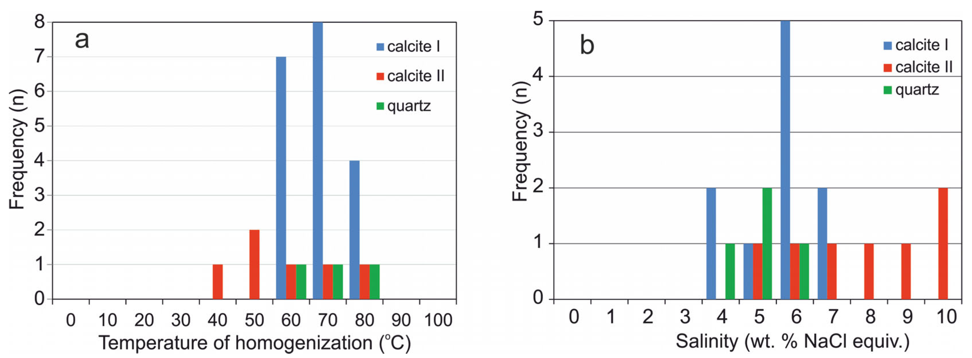
4.5. Fluid Inclusion Studies

Primary and pseudo-secondary fluid inclusions in the synchysite-bearing vein gangue were found to be very small, mostly less than 10 μm in diameter, in all the studied minerals. The inclusions are mostly single-phase (Figure 11a), and two-phase inclusions with very small vapor bubbles (LVR = 0.95) were rarely observed (Figure 11b). The inclusions are of the aqueous type. The temperatures of homogenization of the two-phase inclusions in the first generation of calcite (calcite I, post-uranium stage of mineralization; Figure 2) were measured between 52 and 77 °C, those in the second generation of calcite (calcite II post-uranium stage of mineralization; Figure 2) were measured between 38 and 74 °C, and those in quartz were measured from 58 to 74 °C (Figure 12a).
Both the single-phase and two-phase inclusions were analyzed using cryometry. As the behavior of single-phase inclusions was metastable, the inclusions were heated up to 250 °C to partial homogenization, when a small vapor bubble appeared. The melting temperatures of the last crystal of ice in the calcite I were measured in the range from −2.1 to −4.4 °C, which means the salinity of the aqueous fluid was between 3.6 and 7 wt.% NaCl equiv.
The melting temperatures of ice of the inclusions in the calcite II had values from −2.9 to −6.6 °C, and the salinity of the aqueous fluid corresponded to values from 4.8 to 10 wt.% NaCl equiv. The melting temperatures of ice in the quartz were measured between −2.4 and −3.6 °C, which indicated the salinity of the aqueous fluid to be between 4 and 5.9 wt.% NaCl equiv. (Figure 12b), therefore indicating a possible admixture of saline brines. The temperature of the first melting was observed only in some inclusions. The presence of Te between −35.6 and −38.4 °C probably indicates NaCl and possibly MgCl2 and FeCl2 in the aqueous fluid.
Small fragments of silicates found in the calcite II were shown to contain single-phase inclusions. Phase changes, such as heterogenization, recrystallization, and melting, were observed in these inclusions during cryometry. The features of the phase changes do correspond to the behavior of either CO2 or CH4. The inclusions probably trapped higher hydrocarbons (HHC inclusions). The presence of higher hydrocarbons was proven under fluorescence light, where the inclusions emanated a pale blue color.

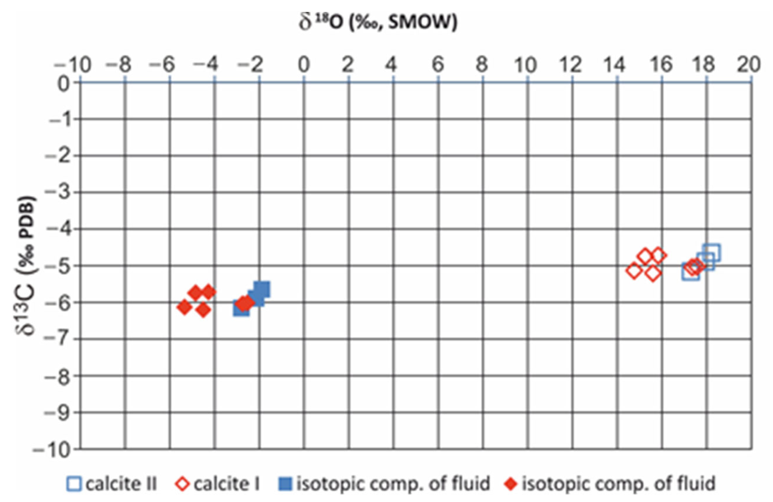
4.6. Stable Isotopes

The values of δ13C of the calcites were found to range from −4.65 to −5.2‰ (PDB). The values of δ18O of the calcites were found to range from 14.76 to 18.22‰ (SMOW). The values of δ13C and δ18O for calcite I and younger calcite II from the synchysite-bearing vein were found to be slightly shifted (Figure 13 and Table S4). The recalculated values of the isotopic composition of the fluid (Th = 70 °C) showed δ13C fluid from −5.65 to −6.2‰ (PDB) and δ18O fluid from −1.88 to −5.34‰ (SMOW).
The isotopic composition of C and O in the calcites was found to be uniform and indicates that constant conditions occurred during vein formation. The interpretation of the isotopic record of C in calcites I and II is ambiguous. The carbon isotopic data could be interpreted as to indicate the deep-seated carbon source, but the contribution of oxidized organic carbon or carbon from dissolved carbonates of previous stages of mineralization cannot be excluded. The source of water in the hydrothermal fluids was mostly from meteoric waters circulating in solidified and cooled rocks, with a possible admixture of saline brines from sedimentary basins. The isotopic data may be compared quite well to the isotopic composition of the post-uranium, low-temperature carbonate veins of the Rožná deposit (δ13C = −4.31 to −5.81‰; δ18O = +12.31 to 18.26‰) [24].

5. Discussion

5.1. Silica Gel Formation and the Origin of Synchysite

The results presented in this work show that the synchysite crystallized at very low temperatures (<100 °C) in a silica gel, which later recrystallized. The silica gel may have formed in the hydrothermal deposits due to a significant decrease in fluid pressure in brittle shear zones [41]. The studied synchysite-bearing vein in the Rožná deposit was found to be separated from the host rocks by small fold lines and contains breccias of the surrounding rocks that border the vein edges (Figure 3a,b). Moreover, the vein was shown to comprise several generations of calcite and quartz with fragments of older uranium mineralization (Figure 4), which indicates the multiple opening and closing of the brittle structures to which the vein with the synchysite is bound. The “fault-valve mechanism” model implies a substantial decrease in fluid pressure and adiabatic cooling following failure on the fault planes, which may have facilitated the deposition of silica gel due to rapid changes in the physical and chemical conditions of the hydrothermal system [42]. The precipitation pathway from a silica-supersaturated fluid begins with the formation of amorphous silica phases and continues to coarser and more crystalline silica phases [42,43,44,45,46]. The same mechanism may explain the formation of silica gels along the fault lines without mineralization [47,48,49,50].
Internal voids in a gel may be formed by either the drying or aging of the gel without access to air. Desiccation cracks are usually continuous and polygonal [51,52]. Without access to air, spontaneous aging, or the contraction of the gel meshwork within itself by the establishment of a greater density of cross-linkages under the influence of van der Waal’s attractive forces, leads to concentrations of supernatant water entering internal voids. This process (syneresis) has been described many times in the literature [53,54]. Syneresis voids are usually discontinuous and very variable in shape [55]. At Rožná, the internal voids were found to be not continuous, and their shapes were shown to range from being linear to very irregular (Figure 6a,d,e). Therefore, the internal voids described in the synchysite-bearing quartz filling at Rožná were most likely formed due to syneresis of original silica gel. These voids were filled during syneresis with fluids that were released as the gel ages.
In addition to internal voids, another very characteristic feature of silica gels is the formation of diffusion structures, often referred to as Liesegang rings or bands. Although the origin of the Liesegang structures is not completely understood [56], they are usually explained as being due to the diffusion of reactants into the gel phase; their periodic supersaturation, nucleation, and precipitation in localized bands; and the depletion of reactants in adjacent zones [54,57,58,59]. This process may be repeated many times to form the “zebra type“ textures that often occur in opals [56,60]. As seen in Figure 6e,f, the internal voids at Rožná are filled with a mixture of fine-grained quartz and hematite, which are encircled by multiple Liesegang bands of hematite with synchysite crystals mostly growing on their outer rims (Figure 6g,h).
As Liesegang bands originate from the diffusion of dissolved species into a gel matrix, it is proposed that the hematite bands in the synchysite-bearing vein in Rožná originated due to the gradual oxidation of Fe2+-bearing solutions. The source of Fe2+ may be seen in the oxidation of pyrite/marcasite in both the carbonate- and quartz-dominated vein filling according to a set of equations proposed by Bethke [61]:
3½O2(aq) + FeS2 + H2O → Fe2+ + 2SO42− + 2H+
SO42− + H+ → HSO4
3½O2 (aq) + FeS2 + H2O → Fe2+ + 2HSO4
½O2(aq) + 2H2O → Fe2O3 + 4H+
In the initial stage of dissolving pyrite in the presence of oxygen, there is a rapid acidification of hydrothermal fluids due to the production of H+ (Equation (1)). With a gradual decrease in pH, the HSO4 becomes more abundant than SO42− due to the protonation of the sulfate (Equation (2)). At this stage, the solution remains almost fixed in an oxidation state and pH, accumulating Fe2+ and HSO4 (Equation (3)) until the pyrite is completely dissolved, and the Fe2+-rich solutions may be accumulated in syneresis voids in the gel from which they may then diffuse into the silica gel matrix. When all pyrite/marcasite is consumed, the dissolved Fe2+ in the internal voids or the Liesegang bands is converted into Fe (hydro) oxides (Equation (4)), which leads to the further fluid acidification of the hydrothermal fluids.
Similar to Fe2+, REEs may be easily transported in an acidic environment even at low temperatures in the form of chloride or hydroxyl complexes, depending on the concentrations of the individual ligands [62,63,64,65]. At near-neutral and alkaline pH, when hydrofluoric acid (HFo) dissociates and releases protons (H+) and F, REEs may also be transported as fluoride complexes. However, in the presence of Ca2+, the concentration of F in the fluids is very low due to the formation of fluorite and the presence of Ba2+, and the formation of highly insoluble barite may limit transport of REEs in sulfate complexes. Therefore, in their summary article on the mobility of REEs in hydrothermal systems, Migdisov et al. [62] referred to chloride ions as a “transport ligand“ as opposed to fluoride and sulfate ions, which they referred to as a “depositional ligand” that causes the precipitation of REE minerals. The fluid inclusion study performed in this research showed that NaCl predominates in the inclusions enclosed in both quartz and calcite, and the presence of small amounts of MgCl2 and FeCl2 cannot be excluded. Therefore, together with Fe2+, the REEs were probably transported in chloride complexes, and the formation of synchysite in Liesegang bands may be described via a reaction suggested by Alles et al. [40]:
REECl2+ + Ca2+ + HF + 2HCO3 = Ca(REE)(CO3)2F + 3H+ + Cl
Equation (5) indicates that the transport of REEs in chloride complexes may be limited due to the neutralization of fluid acidity by near-neutral or alkaline carbonate-bearing solutions released during the syneresis and aging of the silica gel. This corresponds to the presence of calcite, which is often enclosed in the intergranular pores of quartz grains in recrystallized gel (Figure 6j).
A close association between synchysite and hematite is apparent in the Rožná samples, as most of its crystals in the vein were shown to be bound to the outer edges of the Liesegang bands (Figure 6f,g). Fe-(hydro)oxides, ferrihydrite, and hematite are excellent sorbents of REEs [66,67,68]. Moreover, it is also assumed that REEs are not only absorbed but also co-precipitated on the surface of Fe solid phases to form a nucleation layer for the growth of synchysite crystals [69]. In other words, synchysite in Fe-(hydro)oxides-rich zones in the original silica gel may have been formed through a process of supersaturation of an REE-rich solution on the surface of the Fe-(hydro)oxides, resulting in the nucleation and crystallization of synchysite, as well as the consequential depletion in REEs in distal points of the nucleation sites [70,71]. Very close associations between the occurrence of REE fluorocarbonates and hematite have also been reported at the Olympic Dam deposit, Australia [11,72]; the Mary Kathleen deposit in Queensland, Australia [10]; and the quartz vein from Cinquevalli (Trento, Italy) [73].
Silica gels are very unstable in hydrothermal deposits and form spherical, microbotryoidal clusters < 10 μm in size comprising thin-bladed crystals of paracrystalline opal-CT and/or opal-C (lepispheres). Relics of lepispheres (Figure 6c) were found to form “ghost“ structures at Rožná, but they were modified by latter recrystallization to form quartz grains. The nucleation and growth of quartz grain from silica gel is relatively slow under epizonal conditions, and it is very sensitive to impurities in the system [74,75,76]. In Rožná, the most important impurity in the quartz-rich part of the synchysite-bearing vein is the hematite pigment, so the size of the quartz grains in hematite-rich part of the vein is very small (<20 μm) due to fast nucleation provoked by hematite inclusions. This applies in particular to internal voids in original gels and Liesegang bands. With a small amount of hematite pigment (and therefore with a small number of nucleation centers), the original gel more slowly recrystallized to form quartz grains up to 0.8 mm in size, often perpendicularly arranged to the internal voids (Figure 6e,f). Quartz grains rarely form “rosettes” (Figure 6b), which are the result of the growth of authigenic quartz crystals in a silica-supersaturated solution or in voids of silica gels [77].

5.2. Sources of REE for Synchysite Formation

The REE patterns in uranium minerals in low-temperature hydrothermal uranium deposits usually mimic the REE patterns in host rocks [13]. The French uranium deposits (Bois Noirs, Commanderie, Escarpiére) may serve as a typical example [13]. Monazite in the host rocks of the Rožná deposit was found to contain an average of 16.8 wt.% La2O3, 20.8 wt.% Ce2O3, 9.6 wt.%, and 2.9 wt.% Nd2O3 (EMPA data) [78]. Besides monazite, titanite is a characteristic accessory mineral in the host rocks of the Rožná deposit. This mineral, in addition to the major elements, also contains a significant amount of REEs and F (Table S2), as well as trace amounts of U and Th (below the sensitivity of the microprobe). Titanite in the Rožná deposit is usually partially or completely hydrothermally decomposed into a mixture of anatase (verified by Raman spectroscopy), quartz, and carbonates, as well as tiny grains of monazite and xenotime (Figure 5b). Monazite with a monocline structure preferentially incorporates LREEs (La–Gd) in an REEO9 polyhedron, whereas xenotime with a tetragonal structure preferentially incorporates Y and HREEs (Tb-Lu) in an REEO8 polyhedron [79]. At Rožná, hydrothermal monazite is dominated by LREE2O3 (average: 54.91 wt.%), while xenotime contains an average of 41.1 wt.% Y2O3 and small amount of HREE2O3 (average: 13.81 wt.% [80]; Table S3).
The hydrothermal decomposition of titanite may therefore be expressed by the equation (following Bancroft et al. [81]):
Titanite + HPO42− + HCO3 → Anatase + Calcite + Quartz + Monazite + Xenotime
Ca1−xREExTiSiO5 + xHPO42− + 1−xHCO3 → TiO2 + 1−xCaCO3 + 1SiO2 + xREEPO4
The source of HPO42− is likely to be the dissolution of apatite, the corrosion residues of which are a common accessory mineral in strongly altered rocks that accompany uranium mineralization [24], and HCO3 is omnipresent in the altering fluids.
Two types of monazite in altered rocks in the Rožná deposit were also confirmed by chemical dating that was found to range from 480 ± 57 to 324 ± 39 Ma (metamorphic monazite) and around 268 ± 50 Ma (hydrothermal monazite) [25]. The age of the hydrothermal monazite corresponds to the age of the main stage of uranium mineralization in the deposit (U–Pb dating of uraninite: 280 to 260 Ma) [22]. Therefore, metamorphic monazites and hydrothermal monazite, as well as xenotime from either local or deep-seated sources, may be one of the reasons for the enrichment of the emerging coffinitized uraninite and coffinite with REEs.
Uranium minerals may host many elements with ionic radii similar to U4+ in an eightfold coordination. This particularly applies to REEs (REE3+ and Y3+). The incorporation of these elements into the structure of uranium minerals is mainly a function of temperature and element availability [13,82,83,84,85,86]. On the other hand, REE3+ and Y3+ may not enter directly into the structure of uranium minerals; rather, they may be a mixture of uranium mineral nanoparticles and finely dispersed REE phosphates or fluorocarbonates. Many authors have drawn attention to the formation of mixtures of coffinite and dispersed nanoparticles of REE phosphates and fluorocarbonates [12,87,88]. This corresponds to the concentrations of P2O5 (up to 0.66 wt.%) and F (up to 0.28 wt.%) in coffinitized uraninites and coffinites that form a part of the fragments of older uranium mineralization in the synchysite-bearing vein at Rožná (Table S1). The correlation between P and Y in the corroded grain of coffinite with remnants of coffinitized uraninite in the quartz-rich part of the synchysite-bearing vein in the Rožná deposit (Figure 14) may serve as an example. It can be seen from the figure that the increased contents of (probably dispersed) P and Y are only bound to the coffinite, while P and Y are entirely missing in the coffinitized uraninite.
The synchysite-bearing vein at Rožná is a part of the post-uranium mineral assemblage (Figure 2). Mineral assemblages during this period (e.g., the presence of pyrrhotite together with barite or associations of pyrite and marcasite together with hematite) indicate fluctuations in the pO2 of the hydrothermal fluids [25]. The reason for this is likely to be the mixing of surface waters of oxidative character with residual fossil brines during this period [24]. René [89] and Dolníček et al. [90] likewise explained fluctuations in the oxidation state of hydrothermal fluids in the final stage of the development of hydrothermal fluids in numerous uranium deposits of the Bohemian Massif. Under oxidative conditions, and due to the acidification of the system during the dissolution and oxidation of sulfides, the dissolution of primary U minerals (uraninite, coffinitized uraninite, and coffinite) and the release of REEs from their structure have been reported by many authors [83,84,91,92].
We are considering the same mechanism for the formation of synchysite in Rožná. In contrast to uranium, the solubility of REEs at low temperature can be limited by an increase in the fO2 of hydrothermal fluids [93] or by high concentrations of Ca2+ and HCO3 [62]. The source of Ca2+ and HCO3 at Rožná is evidently the dissolution of carbonates in the vein filling containing synchysite. Fluorine sources have been difficult to identify because they may have originated the hydrothermal decomposition of biotite (which contains from 0.25 to 0.29 wt.% of F in unaltered rocks in the Rožná deposit [25]) or F from the deep-seated crustal sources, or they may have been caused by the subsolidus hydrothermal alteration of magmatic rocks, as considered by several authors in the case of fluorite deposits in the European Variscan [40,94,95].

6. Conclusions

The results presented in this article show that synchysite in the Rožná uranium deposit was formed in the final low-temperature stage of hydrothermal system evolution, which was associated with the reactivation of tectonic structures that the older, main stage of uranium mineralization is bound to. This reactivation resulted in fluctuations in the fO2 values of hydrothermal fluids due to the mixing of surface waters of an oxidative character and reduced fossil brines. Moreover, the multiple brecciation and cementation of fragments of older uranium mineralization enclosed in the synchysite-bearing vein demonstrate fluctuations in hydrostatic pressure during the reactivation of previously formed structures. Variations in fluid pressure and adiabatic cooling following failure on the fault planes probably facilitated the formation of silica-supersaturated fluids. The precipitation of the silica gel from the silica-supersaturated fluids was then controlled by feedback between the silica solubility and precipitation rates. Most of the synchysite crystals in the studied vein were found to be bound to hematite bands, which were formed via the diffusion of Fe2+ and its subsequent oxidation to form Fe-(hydro) oxides in the initial gel phase. It is possible to assume that not only the sorption of REEs but also the nucleation and crystallization of synchysite occurred on the surface of Fe-(hydro) oxides. The source of Fe2+ may be found in the dissolution of pyrite, which has formed numerous corroded mineral inclusions in the quartz filling of the vein. The results of the fluid inclusion study in both the carbonate and quartz vein filling indicate that they are dominated by NaCl, the source of which may have been the fossil brines. Therefore, it possible to assume that both Fe2+ and REEs were present in the hydrothermal fluids in the form of chloride complexes. The formation of synchysite may then be explained by the reaction of acidic Fe2+ and REE-rich solutions with Ca2+ HCO3 and F-rich solutions that were released from the silica gel during syneresis or during its aging.
The sources of REEs during synchysite formation are difficult to decipher due to their multiple remobilizations in the mineralization process. Coffinitized uraninite and coffinite relics in the synchysite-bearing vein were found to contain relatively high contents of REEs, the source of which may be seen in the decomposition of metamorphic monazite, which forms a common accessory mineral in the host rocks of the Rožná uranium deposit. Moreover, additional monazite was produced due to the hydrothermal decomposition of titanite in altered host rocks. Xenotime, another product of titanite decomposition, may be regarded as a source of elevated Y content in some coffinite samples.
In the vanning stage of the hydrothermal activity at Rožná, variations of fO2 and pH resulted in the dissolution of coffinitized uraninite and coffinite relics in the synchysite-bearing vein, as well as in the release and short-distance transport of REEs. Therefore, the dissolution of uranium minerals may be seen as a principal source of the REEs in the synchysite formation.
The results of this work not only show the comprehensive recycling of REEs from different sources during the reactivation of tectonic structures and the changing of the composition of fluids in different stages of the hydrothermal system evolution but also suggest that the study of the formation of REE minerals, fluorocarbonates in particular, in uranium deposits can significantly contribute to the understanding of pT conditions in the final stages of ore mineralization processes. Understanding the physical, chemical and tectonic controls that determine the increased amounts of REEs in some uranium deposits is also a prerequisite for the rational appraisal of the possibilities of extracting them as by-products of uranium ore mining in the future and for the development of waste-free technologies.

Supplementary Materials

The following supporting information can be downloaded at: https://www.mdpi.com/article/10.3390/min12060690/s1. Table S1. Electron-microprobe data (in wt.%) for coffinitized uraninite (cofu) and coffinite from the synchysite-bearing vein in the Rožná uranium deposit. Table S2. Chemical composition of titanite in the host rocks of the synchysite-bearing vein in the Rožná uranium deposit. Concentrations of oxides and F in wt.%, EMPA. Table S3. Chemical composition of hydrothermal xenotime and monazite (products of the titanite hydrothermal alteration in Rožná) in wt.%, EMPA. Table S4. Isotope composition of oxygen and carbon in calcites I (older generation) and calcite II (younger generation) from the synchysite-bearing, post-uranium, quartz–carbonate–sulfide vein in Rožná, as well as recalculated isotopic composition of oxygen and carbon of fluid.

Author Contributions

Conceptualization, B.K.; data curation, I.K. and P.P.; formal analysis, I.K.; investigation, F.V., R.Š., R.Č., F.K. and P.D.; methodology, B.K. and R.Š.; writing—original draft, B.K.; writing—review and editing, B.K.; funding acquisition, J.L.; supervision, J.L. All authors have read and agreed to the published version of the manuscript.

Funding

This reserach was supported by the Operational Programme Research, Innovation and Education, [grant number CZ.02.1.01/0.0/0.0/16_026/0008459 (Geobarr)] from the European Regional Development Fund.

Data Availability Statement

Not applicable.

Acknowledgments

We are indebted to Petr Navrátil and Daniel Holeczy from Diamo state enterprise for their technical assistance within the fieldwork, Petr Gadas from Masaryk University for operating the EMPA, Ondra Pour (Czech Geological Survey) for operating the SEM, František Laufek (Czech Geological Survey) for performing the PXRD analyses, and Bohuslava Čejková and Ivana Jačková (Czech Geological Survey) for the carbon and oxygen isotope analyses in calcites. The MS benefited from critical review by three anonymous reviewers and from editorial comments by Charlene Cheng.

Conflicts of Interest

The authors declare no conflict of interest.

References

  1. COM/2020/474 Critical Raw Materials Resilience: Charting a Path towards Greater Security and Sustainability. Communication from the Comission to the European Parlament, the Council, the European Economic and Social Committee and the Committee of thef Regions. COM(2020) 474 Final. PDF, Brussels, 3 September 2020. Available online: https://eurlex.europa.eu/search.html?scope=EURLEX&text=Critical+Raw+Materials+Resilience+2020&lang=en&type=quick&qid=1649519818132&page=2 (accessed on 21 November 2021).
  2. Yang, Z.; Woolley, A. Carbonatites in China: Policies and narratives of reinventing an industry. Res. Policy 2006, 38, 384–394. [Google Scholar]
  3. Yang, X.Y.; Sun, W.D.; Zhang, Y.X.; Zheng, Y.F. Geochemical constraints on the genesis of the Bayan Obo Fe-Nb-REE deposit in Inner Mongolia, China. Geochim. Cosmochim. Acta 2009, 73, 1417–1435. [Google Scholar] [CrossRef]
  4. Fan, H.-R.; Yang, K.-F.; Hu, F.-F.; Liu, S.; Wang, K.-Y. The giant Bayan Obo REE-Nb-Fe deposit, China: Controversy and ore genesis. Geosci. Front. 2016, 7, 335–344. [Google Scholar] [CrossRef]
  5. Kynicky, J.; Smith, M.P.; Xu, C. Diversity of rare earth deposits: The key example of China. Elements 2012, 8, 361–367. [Google Scholar] [CrossRef]
  6. Elliott, H.A.L.; Wall, F.; Chakhmouradian, A.R.; Siegfried, P.R.; Dahlgren, S.; Weatherley, S.; Finch, A.A.; Marks, M.A.W.; Dowman, E.; Deady, E. Fenites associated with carbonatite complexes: A review. Ore Geol. Rev. 2018, 93, 38–59. [Google Scholar] [CrossRef]
  7. Hatch, G.P. Dynamics in the global market for rare earths. Elements 2012, 8, 341–346. [Google Scholar] [CrossRef]
  8. Simandl, G.J. Geology and market-dependent significance of rare earth element resources. Miner. Depos. 2014, 49, 889–904. [Google Scholar] [CrossRef]
  9. Groves, D.I.; Bierlein, F.P.; Meinert, L.D.; Hitzman, W. Iron Oxide Copper-Gold (IOCG) Deposits through Earth history: Implications for origin, lithospheric setting, and distinction from other epigenetic iron oxide deposits. Econ. Geol. 2010, 105, 641–654. [Google Scholar] [CrossRef] [Green Version]
  10. Reynolds, L.J. Geology of the Olympic Dam Cu-U-Ag-REE deposit. In Hydrothermal Iron Oxide Copper-Gold & Related Deposits: A Global Perspective; Porter, T.D., Ed.; Australian Mineral Foundation: Adelaide, Australia, 2000; pp. 93–104. [Google Scholar]
  11. Oreskes, N.; Einaudi, M.T. Origin of Origin of rare earth element-enriched hematite breccias at the Olympic Dam Cu-U-Au-Ag deposit, Roxby Downs, South Australia. Econ. Geol. 1990, 85, 1–28. [Google Scholar] [CrossRef]
  12. Fayek, M.; Kyser, T.K. Characterization of multiple fluid-flow events and rare-earth-element mobility associated with formation of unconformity-type uranium deposits in the Athabasca basin, Saskatchewan. Can. Miner. 1997, 35, 627–658. [Google Scholar]
  13. Mercadier, J.; Cuney, M.; Cathelineau, M.; Lacorde, M. Origin of uranium deposits revealed by their rare earth element signature. Terra Nova 2011, 23, 264–269. [Google Scholar] [CrossRef]
  14. Roscoe, S.M. Paleoplacer uranium gold. In Geology of Canadian Minerals International Workshop, Geology of Rare Metals, Deposit Types; Geology of Canada Series no. 8; Eckstrand, O.R., Sinclair, W.D., Thorp, R.I., Eds.; Geological Survey of Canada: Otawa, ON, Canada, 1996; pp. 10–23. [Google Scholar]
  15. Cox, J.J.; Ciuculescu, T.; Hwozdyk, T.; Altman, L. Technical Report on the Eco Ridge Mine Rare Earths and Uranium Project, Elliot Lake, Ontario, Canada; Roscoe Postle Associates Inc.: Toronto, ON, Canada, 2011; Available online: http://www.pelemountain.com/pdf/0092011pea.pdf (accessed on 20 November 2020).
  16. Kwak, T.A.P.; Abeysinge, P.B. Rare earth and uranium minerals present present as daugthther crystals in fluid inclusion, Mary Kathleen U-REE skarn, Queensland, Australia. Miner. Mag. 1987, 51, 665–670. [Google Scholar] [CrossRef]
  17. René, M. Anomalous rare earth element, yttrium and zirconium mobility associated with uranium mineralization. Terra Nova 2008, 20, 52–58. [Google Scholar] [CrossRef]
  18. Bukovská, Z.; Švagera, O.; Chabr, T.; Leichmann, J.; Sosna, K. Data Mining from the Deep Horizons of the Rožná Mine; Final Report; Czech Geological Survey: Prague, Czech Republic, 2020; p. 691, unpublished work. [Google Scholar]
  19. Deiller, P.; Štípská, P.; Ulrich, M.; Schulmann, K.; Collett, S.; Peřestý, V.; Hacker, B.; Kylander-Clark, A.; Whitechurch, H.; Lexa, O.; et al. Eclogite subduction wedge intruded by arc-type magma: The earliest record of Variscan arc in the Bohemian Massif. Gondwana Res. 2021, 99, 220–246. [Google Scholar] [CrossRef]
  20. OECD. Uranium 2020: Resources, Production and Demand. In A Joint Report by the Nuclear Energy Agency and the International Atomic Energy Agency; NEA No. 7551; OECD: Boulogne-Billancourt, France, 2020; p. 47. [Google Scholar]
  21. Arapov, J.A.; Bojcov, V.J.; Czesnokov, N.I.; Djakonov, A.V.; Halbrštát, J.; Yakovenko, M.; Kolek, M.; Komínek, J.; Kozyrev, G.A.; Lazanský, M.; et al. Uranium Deposits of the Czechoslovakia; Czechoslovak Uranium Industry: Prague, Czech Republic, 1984; p. 420. (In Czech) [Google Scholar]
  22. Anderson, E.B.; Ivanov, P.A.; Komínek, J. Ore metasomatism at the uranium veins of the Rožná deposit. Geol. Hydrometal Uranium 1988, 12, 70–88. (In Czech) [Google Scholar]
  23. Hein, U.; Lehmann, B.; Křibek, B.; René, M. Evolution of ore-forming fluids along the Rožná- shear zone, Bohemian Massif, Czech Republic: Implication for local uranium deposition and comparison with U-mineralization at Schlema, Erzgebirge, Germany. In Proceedings of the International Symposium Uranium Deposits: From their Genesis to their Environmental Aspects, Prague, Czech Republic, 10–11 September 2002; Kříbek, B., Zeman, J., Eds.; Czech Geological Survey: Prague, Czech Republic, 2002; pp. 61–64. [Google Scholar]
  24. Kříbek, B.; Žák, K.; Dobeš, P.; Leichmann, J.; Pudilová, M.; René, M.; Scharm, B.; Scharmová, M.; Hájek, A.; Holeczy, D.; et al. The Rožná uranium deposit (Bohemian Massif, Czech Republic): Shear zone-hosted, late Variscan and post-Variscan hydrothermal mineralization. Miner. Depos. 2009, 44, 99–128. [Google Scholar] [CrossRef]
  25. Kříbek, B.; Hájek, T. (Eds.) The Rožná Uranium Deposit: A Model of Late-Variscan and Post-Variscan Mineralization; Czech Geological Survey: Prague, Czech Republic, 2005; p. 89. ISBN 80-7075-629-2. (In Czech) [Google Scholar]
  26. Dempírová, L.; Vitková, H. Methods of Certified Chemical Analyses; Czech Geological Survey: Prague, Czech Republic, 2002; p. 230. (In Czech) [Google Scholar]
  27. Merlet, C. An accurate Computer correction program for quantitative electron probe microanalysis. Microchim. Acta 1994, 114, 363–376. [Google Scholar] [CrossRef]
  28. Bruker, A.X.S. Topas 5; Bruker AXS GmbH: Karlsruhe, Germany, 2015; p. 247. [Google Scholar]
  29. Bruker, A.X.S. DIFFRAC.EVA, Version 4.1; Bruker AXS GmbH: Karlsruhe, Germany, 2017; p. 230. [Google Scholar]
  30. Bodnar, R.J.; Vitik, M.O. Interpretation of microthermometric data for H2O-NaCl fluid inclusions. In Fluid Inclusions in Minerals: Methods and Applications. Short Course of the Working Group “Inclusions in Minerals”; Blacksburg, V.A., De Vivo, B., Frezzotti, M.L., Eds.; Virginia Polytechnic Institute: Blacksburg, VA, USA, 1994; pp. 117–130. [Google Scholar]
  31. Davis, D.W.; Lowenstein, T.M.; Spencer, R.J. Melting behavior of fluid inclusions in laboratory-grown halite crystals in the systems NaCl-H2O, NaCl-KCl-H2O, NaCl-MgCl2-H2O, and NaCl-CaCl2-H2O. Geochim. Cosmochim. Acta 1990, 54, 591–601. [Google Scholar] [CrossRef]
  32. Goldstein, R.H.; Reynolds, T.J. Systematics of fluid inclusions in diagenetic minerals. In SEPM Short Course No. 31; SEPM Society for Sedimentary Geology: Tulsa, OK, USA, 1994; p. 199. [Google Scholar]
  33. McCrea, J.M. On the isotopic chemistry of carbonates and a paleotemperature scale. J. Chem. Phys. 1950, 18, 849–857. [Google Scholar] [CrossRef]
  34. Kim, S.T.; O’Neil, J.R. Equilibrium and nonequilibrium oxygen isotope effects in synthetic carbonates. Geochim. Cosmochim. Acta 1997, 61, 3461–3475. [Google Scholar] [CrossRef]
  35. Boynton, W.V. Cosmochemistry of the rare earth elements: Meteorite studies. Dev. Geochem. 1984, 2, 63–114. [Google Scholar]
  36. Irber, W. The lanthanide tetrad effect and its correlation with K/Rb, Eu/Eu*, Sr/Eu, Y/Ho, and Zr/Hf of evolving peraluminous granite suites. Geochim. Cosmochim. Acta 1999, 63, 489–508. [Google Scholar] [CrossRef]
  37. Scheetz, B.E.; White, W.B. Vibrational spectra of the alkaline earth double carbonates. Am. Miner. 1977, 62, 36–50. [Google Scholar]
  38. Wehrmeister, U.; Soldati, A.L.; Jacob, D.E.; Häger, T.; Hofmeister, W. Raman spectroscopy of synthetic, geological and biological vaterite: A Raman spectroscopic study. J. Raman Spectrosc. 2010, 41, 193–201. [Google Scholar] [CrossRef]
  39. Frost, R.L.; Dickfos, M.J. Raman spectroscopy of halogen-containing carbonates. J. Raman Spectrosc. 2007, 38, 1516–1522. [Google Scholar] [CrossRef] [Green Version]
  40. Alles, J.; Ploch, A.M.; Schirmer, T.; Nolte, N.; Liessmann, W.; Lehmann, B. Rare-earth-element enrichment in post-Variscan polymetallic vein systems of the Harz Mountains, Germany. Miner. Depos. 2019, 54, 307–328. [Google Scholar] [CrossRef]
  41. Herrington, R.J.; Wilkinson, J.J. Colloidal gold and silica in mesothermal vein systems. Geology 1993, 21, 539–542. [Google Scholar] [CrossRef]
  42. Sibson, I.R.H.; Scott, J. Stress/fault controls on the containment and release of overpressured fluids: Examples from gold-quartz vein systems in Juneau, Alaska; Victoria, Australia and Otago, New Zealand. Ore Geol. Rev. 1998, 13, 293–306. [Google Scholar] [CrossRef]
  43. Oehler, J.H. Hydrothermal crystallization of silica gel. Geol. Soc. Am. Bull. 1976, 87, 1143–1152. [Google Scholar] [CrossRef]
  44. Williams, L.A.; Crerar, D.A. Silica diagenesis. II. General mechanisms. J. Sediment. Petrol. 1985, 55, 312–321. [Google Scholar]
  45. Williams, L.A.; Pasts, G.A.; Crerar, D.A. Silica diagenesis, I. Solubility controls. J. Sediment. Petrol. 1985, 55, 301–311. [Google Scholar]
  46. Rimstidt, J.D.; Barnes, H.L. The kinetics of silica-water reactions. Geochim. Cosmochim. Acta 1980, 44, 1683–1699. [Google Scholar] [CrossRef]
  47. Onasch, C.M.; Farver, J.R.; Dunne, W.M. The role of dilatation and cementation in the formation of cataclasite in low temperature deformation of well cemented quartz-rich rocks. J. Struct. Geol. 2010, 32, 1912–1922. [Google Scholar] [CrossRef]
  48. Nakamura, Y.; Muto, J.; Nagahama, H.; Shimizu, I.; Miura, T.; Arakawa, I. Amorphization of quartz by friction: Implication to silica-gel lubrication of fault surfaces. Geophys. Res. Lett. 2012, 39, 1–6. [Google Scholar] [CrossRef]
  49. Borhara, K.; Onasch, C.M. Evidence for silica gel and its role in faulting in the Tuscarora sandstone. 2020. J. Struct. Geol. 2020, 139, 104140. [Google Scholar] [CrossRef]
  50. Hayashi, N.; Tsutsumi, A. Deformation textures and mechanical behavior of a hydrated amorphous silica formed along an experimentally produced fault in chert. Geophys. Res. Lett. 2010, 37, 1–5. [Google Scholar] [CrossRef]
  51. Schubel, K.A.; Simonson, B.M. Petrography and diagenesis of chert formation from lake Magadi, Kenya. J. Sediment. Petrol. 1990, 60, 761–776. [Google Scholar]
  52. Pauchard, L.; Parisse, F.; Allain, C. Influence of salt content on crack patterns formed through colloidal suspension desiccation. Phys. Rev. E 1999, 59, 3737. [Google Scholar] [CrossRef]
  53. Scherer, G.W. Mechanics of syneresis I. Theory. J. Non-Cryst. Solids 1989, 108, 18–27. [Google Scholar] [CrossRef]
  54. Elliston, J. Hydration of silica and its role in the formation of quartz veins—Part 1. Substantia 2018, 2, 43–71. [Google Scholar] [CrossRef]
  55. Plummer, P.S.; Gostin, A.V. Shrinkage cracks: Desiccation or synaeresis? J. Sediment. Res. 1981, 51, 1147–1156. [Google Scholar] [CrossRef]
  56. Krug, H.-J.; Brandtstadter, H.; Jacob, K.H. Morphological instabilities in pattern formation by precipitation and crystallization processes. Geol. Rundsch. 1996, 85, 19–28. [Google Scholar] [CrossRef]
  57. Ostwald, W. A-Linien von R. E. Liesegang (paper review). Z. Phys. Chem. 1897, 23, 365. [Google Scholar]
  58. Lagzi, I. Simulation of Liesegang patterns: Effect of reversible complex formation of precipitate. J. Phys. Chem. B 2003, 107, 13750–13753. [Google Scholar] [CrossRef]
  59. George, J.; Varghese, G. Intermediate colloidal formation and the varying width of periodic precipitation bands in reaction–diffusion systems. J. Colloid Interface Sci. 2005, 282, 397–402. [Google Scholar] [CrossRef] [PubMed]
  60. Liesegang, M.; Milke, R. Australian sedimentary opal-A and its associated minerals: Implications for natural silica sphere formation. Am. Miner. 2014, 99, 1488–1499. [Google Scholar] [CrossRef]
  61. Bethke, C.M. Geochemical Reaction Modeling. In Concepts and Applications; Oxford University Press: New York, NY, USA; Oxford, UK, 1996; p. 397. [Google Scholar]
  62. Migdisov, A.; Williams-Jones, A.E.; Brugger, J.; Caporuscio, F.A. Hydrothermal transport, deposition, and fractionation of the REE: Experimental data and thermodynamic calculations. Chem. Geol. 2016, 439, 13–42. [Google Scholar] [CrossRef] [Green Version]
  63. Loges, A.; Migdisov, A.A.; Wagner, T.; Williams-Jones, A.E.; Markl, G. An experimental study of the aqueous solubility and speciation of Y(III) fluoride at temperatures up to 250 °C. Geochim. Cosmochim. Acta 2013, 123, 403–415. [Google Scholar] [CrossRef]
  64. Migdisov, A.A.; Williams-Jones, A.E. Hydrothermal transport and deposition of the rare earth elements by fluorine bearing aqueous liquids. Miner. Depos. 2014, 49, 987–997. [Google Scholar] [CrossRef]
  65. Perry, P.E.; Gysi, A.P. Rare earth elements in mineral deposits: Speciation in hydrothermal fluids and partitioning in calcite. Geofluids 2018, 5382480. [Google Scholar] [CrossRef] [Green Version]
  66. Bau, M. Scavenging of dissolved yttrium and rare earths by precipitating iron oxyhydroxide: Experimental evidence for Ce oxidation, Y-Ho fractionation, and lanthanide tetrad effect. Geochim. Cosmochim. Acta 1999, 63, 67–77. [Google Scholar] [CrossRef]
  67. Fei, Y.; Hua, J.; Liu, C.; Li, F.; Zhu, Z.; Xiao, T.; Chen, M.; Gao, T.; Wei, Z.; Hao, L. Aqueous Fe(II)-induced phase transformation of ferrihydrite coupled adsorption/immobilization of rare earth elements. Minerals 2018, 8, 357. [Google Scholar] [CrossRef] [Green Version]
  68. Yang, M.; Liang, X.; Li, Y.; He, H.; Zhu, R.; Arai, Y. Ferrihydrite transformation impacted by adsorption and structural incorporation of rare earth elements. ACS Earth Space Chem. 2021, 5, 2768–2777. [Google Scholar] [CrossRef]
  69. Piasecki, W.; Sverjensky, D.A. Speciation of adsorbed yttrium and rare earth elements on oxide surfaces. Geochim. Cosmochim. Acta 2008, 72, 3964–3979. [Google Scholar] [CrossRef]
  70. Ortoleva, P.; Merino, E.; Moore, C.; Chadam, J. Geochemical self-organisation 1: Reaction-transport feedbacks and modeling approach. Am. J. Sci. 1987, 287, 979–1007. [Google Scholar] [CrossRef]
  71. Barker, S.L.L.; Cox, S.F.; Eggins, S.M.; Gagan, M.K. Microchemical evidence for episodic growth of individual growth of antitaxial veins during fracture-controlled fluid flow. Earth Planet. Sci. Lett. 2006, 250, 331–344. [Google Scholar] [CrossRef]
  72. Verdugo-Ihl, M.R.; Ciobanu, C.L.; Cook, N.J.; Ehrig, K.J.; Courtney-Davies, L.; Gilbert, S. Textures and U-W-Sn-Mo signatures in hematite from the Olympic Dam Cu- U-Au-Ag deposit, South Australia: Defining the archetype for IOCG deposits. Ore Geol. Rev. 2017, 91, 173–195. [Google Scholar] [CrossRef]
  73. Capitani, G. Synchysite-(Ce) from Cinquevalli (Trento, Italy): Stacking Disorder and the Polytypism of (Ca,REE)-Fluorcarbonates. Minerals 2020, 10, 77. [Google Scholar] [CrossRef] [Green Version]
  74. Huang, W.-L. The nucleation and growth of polycrystalline quartz: Pressure effect from 0.05 to 3 GPa. Eur. J. Miner. 2003, 15, 843–853. [Google Scholar] [CrossRef] [Green Version]
  75. Lagoerio, L.; Barbosa, P. Nucleation and growth of new grains in recrystallized quartz vein: An example from banded ore formation in Iron Quadrangle, Brazil. J. Struct. Geol. 2010, 32, 595–604. [Google Scholar] [CrossRef] [Green Version]
  76. Buckley, P.; Hargreaves, N.; Cooper, S. Nucleation of quartz under ambient conditions. Commun. Chem. 2018, 1, 49. [Google Scholar] [CrossRef]
  77. Herdianita, N.R.; Browne, P.R.L.; Rodgers, K.A.; Campbell, K.A. Mineralogical and textural changes accompanying ageing of silica sinter. Miner. Depos. 2000, 35, 48–62. [Google Scholar] [CrossRef]
  78. Leichmann, J.; Matula, M.; Broska, I.; Holeczy, D. Low-degree partial melting of metapelites—Another possible implement for selective concentration of uranium: Example from the Rožná uranium deposit, Bohemian Massif. In Proceedings of the International Workshop Uranium Deposits: From Their Genesis to Their Environmental Aspects, Prague, Czech Republic, 10–11 September 2002; Kříbek, B., Zeman, J., Eds.; Czech Geological Survey: Prague, Czech Republic, 2002; pp. 75–78. [Google Scholar]
  79. Ni, Y.; Huges, J.M.; Marianno, M.N. Crystal chemistry of the monazite and xenotime structures. Am. Miner. 1995, 80, 21–26. [Google Scholar] [CrossRef]
  80. Kříbek, B.; Veselovský, F.; Knésl, I.; Pour, O.; Pořádek, P.; Hak, J.; Škoda, R.; Leichmann, J. Coffinite-Zr-Ti-(REE-Y) mineralization in deeper parts of the Rožná uranium deposit, Czech Republic. In The Critical Role of Minerals in the Carbon-Free Future, Proceedings of the 16th SGA Biennial Meeting, Rotorua, New Zealand, 28–31 March 2022; Cristie, A., Ed.; Society of Geology Applied to Mineral Deposits: Rotorura, New Zealand, 2022; Volume 1, pp. 188–191. [Google Scholar]
  81. Bancroft, G.M.; Metson, J.B.; Kresovic, R.A.; Nesbitt, H.W. Leaching studies of natural and synthetic titanites using secondary ion mass spectrometry. Geochim. Cosmochim. Acta 1987, 51, 911–918. [Google Scholar] [CrossRef]
  82. Fryer, B.J.; Taylor, R.P. Rare-earth element distributions in uraninites: Implications for ore genesis. Chem. Geol. 1987, 63, 101–108. [Google Scholar] [CrossRef]
  83. Balboni, E.; Simonetti, A.; Spano, T.; Cook, N.D.; Burns, P.C. Rare-earth element fractionation in uranium ore and its U(VI) alteration minerals. Appl. Geochem. 2017, 87, 84–92. [Google Scholar] [CrossRef]
  84. Janeczek, R.; Ewing, C. Dissolution and alteration of uraninite under reducing conditions. J. Nucl. Mater. 1992, 190, 157–173. [Google Scholar] [CrossRef]
  85. Frimmel, H.E.; Schedel, S.; Brätz, H. Uraninite chemistry as forensic tool for provenance analysis. Appl. Geochem. 2014, 48, 104–121. [Google Scholar] [CrossRef]
  86. Burns, P.C.; Finch, R. Uranium: Mineralogy, Geochemistry and the Environment; Mineralogical Society of America: Washington, DC, USA, 1999. [Google Scholar]
  87. Stille, P.; Gauthier-Lafaye, F.; Jensen, K.A.; Salah, S.; Bracke, G.; Ewing, R.C.; Louvat, D.; Million, D. REE mobility in groundwater proximate to the natural fission reactor at Bangombé (Gabon). Chem. Geol. 2003, 198, 289–304. [Google Scholar] [CrossRef]
  88. Macmillan, E.; Cook, N.J.; Ehrig, K.; Ciobanu, C.L.; Pring, A. Uraninite from the Olympic Dam IOCG-U-Ag deposit: Linking textural and compositional variation to temporal evolution. Am. Miner. 2016, 101, 1295–1320. [Google Scholar] [CrossRef]
  89. René, M. Rare-earth, yttrium and zirconium mobility associated with the uranium mineralisation at Okrouhlá Radouň, Bohemian Massif, Czech Republic. Eur. J. Miner. 2015, 27, 57–70. [Google Scholar] [CrossRef]
  90. Dolníček, Z.; René, M.; Hermannová, S.; Prochaska, W. Origin of the Okrouhlá Radouň episyenite-hosted uranium deposit, Bohemian Massif, Czech Republic: Fluid inclusion and stable isotope constraints. Miner. Depos. 2014, 49, 409–425. [Google Scholar] [CrossRef]
  91. Göb, S.; Gühring, J.-E.; Bau, M.; Markl, G. Remobilization of U and REE and the formation of secondary minerals in oxidized U deposits. Am. Miner. 2013, 98, 530–548. [Google Scholar] [CrossRef]
  92. Zhao, D.; Ewing, R.C. Alteration products of uraninite from the Colorado Plateau. Radiochim. Acta 2000, 88, 739–750. [Google Scholar] [CrossRef]
  93. Papoutsa, A.; Pe-Piper, G. Variation of REE-hydrothermal circulation in complex shear zones: The Cobequid Highlands, Nova Scotia. Can. Miner. 2014, 52, 943–968. [Google Scholar] [CrossRef]
  94. Förster, H.J. Synchysite-(Y)-synchysite-(Ce) solid solutions from Markersbach, Erzgebirge, Germany: REE and Th mobility during high-T alteration of highly fractionated aluminous A-type granites. Miner. Petrol. 2001, 72, 259–280. [Google Scholar] [CrossRef]
  95. Dill, H.G.; Hansen, B.T.; Weber, B. REE contents, REE minerals and Sm/Nd isotopes of granite-and unconformity-related fluorite mineralization at the western edge of the Bohemian Massif: With special reference to the Nabburg-Wölsendorf District, SE Germany. Ore Geol. Rev. 2011, 40, 132–148. [Google Scholar] [CrossRef]
Figure 1. (a): A sketch of the Variscan belt of Central and Western Europe (following [19]); (b): simplified geological map of the Bohemian Massif and location of the uranium deposits discussed in the text. Abbreviations in (a): BM: Bohemian Massif; MC: Massif Central; AM: Armorican Massif; BF: Black Forest; VM: Vosges Massif; RM: Rhenish Massif. Abbreviations in (b): MZ: Moldanubian zone (allochthonous unit); Gr: Pre-Variscan and Variscan granitoids; TBU: Teplá–Barrandian Zone (Neoproterozoic and Lower Paleozoic sediments and volcanites); SAXTHUR: Saxothuringian Zone (para-autochthonous and autochthonous units);WS: West Sudetes (paraautochthonous and allochthonous units);LU: Lugian Zone (exotic terrane and autochthonous units); MSZ: Moravian–Silesian Zone (exotic or Avalonian units); CB: Culm basin; PC: Platform cover (Cretaceous and Tertiary sediments).
Minerals 12 00690 g001
Figure 3. Macrostructures of the quartz–carbonate–sulfide vein with synchysite. (a): The synchysite-bearing vein mainly consists of quartz–carbonate and is locally separated from the albitized and graphitized gneiss host rocks by small structures of brittle deformation (yellow dashed lines). Yellow–green coatings on the vein surface, which comprise a mixture of jarosite and secondary uranium minerals, indicate the presence of fragments of older uranium mineralization. (b): The vein comprises several generations of calcite and quartz, and it encloses abundant clasts of host rocks along its edges. (c): Single generations of predominantly quartz and calcite sections of the vein are very often separated by up to 5 mm thick accumulations of authigenic pyrite and marcasite. The synchysite is bound to quartz-rich sections of the vein that are strongly colored by hematite. Explanations: Cb: Carbonate; Qtz: quartz; Py: pyrite.
Minerals 12 00690 g003
Figure 4. (a): The BSE image of breccia with uranium mineralization (white spots) embedded in the carbonate filling of the synchysite-bearing vein. (b): Close-up of the coffinitized uraninite and coffinite in the breccia fragment. An irregular shape of the coffinite accumulations indicate its corrosion and dissolution. Explanation: Urn(cof): coffinitized uraninite; Cof: coffinite; Cal: calcite.
Minerals 12 00690 g004
Figure 5. (a): The BSE image of the chloritized and graphitized host rock with hydrothermally decomposed titanite grains. (b): Close-up of the hydrothermally altered titanite grain decomposed to anatase, quartz, calcite, monazite, and xenotime (white grains) in the chloritized matrix of the host rock of the synchysite-bearing vein. Explanation of symbols: Ap: apatite; Ab: albite; Ant: anatase; Bt: biotite (chloritized); Cal: calcite; Gf: graphite; Ch: chlorite; Mnz: monazite; Py: pyrite; Tnt (altered): hydrothermally altered titanite; Xtm: xenotime.
Minerals 12 00690 g005
Figure 6. Textures of the synchysite-bearing quartz gangue of the vein. (a): Photomicrograph of the quartz gangue with numerous wormy clusters of hematite; plane polarizers. (b): Quartz rosette in coarse quartz vein filling; plane polarizers. (c): A fine-grained mosaic of quartz grains stained with hematite that exhibits a fibrous internal fabric resembling agate with a corroded pyrite grain linen, with hematite (black color) in the central part of the photomicrograph; plane polarizers, combined transmitted and reflected light. (d): Vermicular structures comprising hematite and fine-grained quartz in coarse-grained filling of the quartz gangue; plane polarizers. (e): A linear structure in the coarse-grained quartz filling, which consists of a mixture of fine-grained quartz and hematite. (f): The same photomicrograph as (e) with crossed polarizers. The image clearly shows the linear structure overgrown by elongated quartz grains perpendicularly oriented to the hematite-rich linear structure during the recrystallization of the quartz-rich vein filling. (g): Linear structure comprising a central hematite-rich area that is rimmed on both sides by diffuse hematite layers. Synchysite crystals are bound to these outer hematite-rich rims; plane polarizes. (h): The same as in (g) with crossed polarizers. (i): Deformation of hematite-rich bands during recrystallization of quartz vein filling; plane polarizers. (j): A hematite-pigmented calcite grain enclosed in a mosaic consisting of coarse-grained quartz grains; plane polarizers. (k): Younger carbonate veinlets (calcite II) in the quartz gangue; plane polarizers. (l): A corroded fragment of sphalerite in the quartz gangue; plane polarizers.
Minerals 12 00690 g006
Figure 7. C3 chondrite–normalized REE distribution in the quartz–carbonate–sulfide vein with synchysite and the host rocks. (whole rock data were normalized following [35]). Explanation: veins V1–V3: quartz-dominated section of the vein; V4: quartz and carbonate filling; V5: carbonate-rich section of the vein; host rocks H1–H4: chloritized, argillized, and albitized gneisses; H5: slightly chloritized gneiss.
Minerals 12 00690 g007
Figure 8. Raman spectrum of synchysite-(Ce) between 200 and 1550 cm−1. Bands labeled with (Q) belong to quartz, and bands labeled with (r) belong to a synthetic resin from a thin section.
Minerals 12 00690 g008
Figure 9. Back-scattered electron (BSE) images and areal distribution of Ca, Ce, La, Nd, Y and F (false colors) in synchysite enclosed in the quartz gangue of the synchysite-bearing quartz–carbonate–sulfide vein in the Rožná uranium deposit. The X-ray distribution maps were collected using an EDS detector on a TESCAN MIRA 3.
Minerals 12 00690 g009
Figure 10. C3-chondrite-normalized REE distribution in synchysite of the quartz–carbonate–sulfide vein from the Rožná uranium deposit.
Minerals 12 00690 g010
Figure 11. (a): Single-phase primary inclusions of the H2O type in the quartz from the synchysite-bearing vein. (b): Two-phase pseudosecondary fluid inclusions of the H2O type in the calcite I from the synchysite-bearing vein.
Minerals 12 00690 g011
Figure 12. (a): Histograms of the temperatures of homogenization and (b): salinities of the fluid inclusions in the calcites and quartz.
Minerals 12 00690 g012
Figure 13. Isotopic composition of carbon and oxygen from calcite I and calcite II from the quartz–carbonate–sulfide vein. Explanations: empty symbols: measured data; filled symbols: isotopic composition of hydrothermal fluids.
Minerals 12 00690 g013
Figure 14. Corroded coffinite grain with a coffinitized remnant of uraninite (BSE) in the quartz-rich part of the synchysite-bearing vein in the Rožná uranium deposit and the areal distribution of Si, Ca, U, Y, and P within the grain (false colors).
Minerals 12 00690 g014
Table 1. Concentration of the main and trace elements in the quartz–carbonate–sulfide vein and in host rocks. Main elements are expressed in wt.%, and concentrations of trace elements are expressed in ppm.
SampleQuartz–Carbonate–Sulfide Vein (V)Host Rocks (H)
V1qtzV2qtzV3qtz V4qtz/carbV5carbH1H2H3H4H5
SiO281.8789.2689.4785.2569.8258.2059.9144.0651.2162.04
TiO20.040.040.060.210.060.830.060.480.491.18
Al2O31.401.601.663.642.2420.7218.3212.4412.8113.52
Fe2O30.490.090.091.000.103.640.642.381.520.88
FeO0.210.280.290.520.551.400.403.891.392.94
MgO0.060.040.030.230.050.270.271.670.470.90
MnO0.130.100.100.070.200.040.040.180.170.13
CaO7.433.603.502.8114.881.114.7414.0911.864.86
SrOb.d.l.b.d.l.b.d.l. b.d.l.b.d.l.0.010.020.040.020.01
BaO0.010.010.010.030.020.030.100.070.070.04
Li2O0.010.0050.0050.010.010.0020.0010.0040.0030.002
Na2O0.030.090.070.080.0310.679.274.756.490.11
K2O0.180.140.100.870.091.121.020.330.133.39
P2O50.020.040.020.070.020.110.010.220.180.20
F0.050.060.050.050.020.090.020.050.030.10
CO26.603.092.912.2911.260.403.4811.079.335.21
C(graphite)0.140.110.120.070.020.030.031.291.140.13
S(tot.)0.500.190.231.130.620.010.030.050.041.14
H2O(+)b.d.l. 0.590.580.83b.d.l. 0.910.812.451.412.65
H2O(−)0.200.210.230.470.250.300.190.560.500.59
Total99.36199.54699.52599.639100.2399.8999.36100.0799.26100.02
As 5124612610213617211824.820.42
Ba10964822332207889103159199.38
Bib.d.l.b.d.l.b.d.l.b.d.l.b.d.l.0.080.090.080.090.12
Co3b.d.l.b.d.l.12614.6141515.414.82
Crb.d.l.b.d.l.b.d.l.16114757476156.54
Cu43319972.168.271.2100.5114.25
Mo2913101241533.623.63.323.393.63
Nb3b.d.l.b.d.l.b.d.l.86.036.336.457.026.73
Ni98826932.239383936
Pb135215202158473209613477126104102
Rb16111165136058595660
Sr2823204138231227230230224
Th16162462455565
U307152253677329131133137147126
V41201525765118123122144133
Zn1493105665480142270689383706313469
Zr25665420157104147164141
Explanations of the vein samples: qtz: quartz-dominated sample; qtz/carb: a mixture of quartz and carbonate; carb: carbonate-dominated sample; b.d.l.: concentrations below the detection limit.
Table 2. Representative whole rock REE contents of the synchysite-bearing quartz–carbonate–sulfide vein (V) and data for the host rocks (H) in the Rožná uranium deposits. Data are in ppm. For an explanation of symbols, see Table 1.
SampleV1V2V3V4V5H1H2H3H4H5
La648973103219614224.326.335.633.729.9
Ce10921619170133926055.157.078.473.766.1
Pr15022623847.134.17.517.2610.79.368.68
Nd55082286219014124.626.235.332.729.7
Sm97.61451553625.25.285.437.126.836.10
Eu19.627.429.87.945.771.731.651.741.821.70
Gd64.996.110323.616.35.335.526.847.166.18
Tb6.179.2110.62.991.890.730.821.050.920.85
Dy24.835.338.413.67.714.564.735.625.054.95
Y12616717573.641.227.927.930.529.628.9
Ho3.584.896.152.391.271.120.951.351.161.08
Er6.919.1510.435.972.942.932.732.922.832.83
Tm0.620.690.730.800.360.450.420.530.450.43
Yb2.632.532.784.391.962.562.322.552.722.50
Lu0.320.290.300.560.260.320.450.430.410.38
ΣREE 279241374366944680165169221208190
LaN/SmN4.184.234.203.463.542.903.043.153.103.09
LaN/YN16625925030.148.76.417.639.428.358.08
DyN/YbN6.139.058.972.012.561.161.321.431.211.29
Ce/Ce*0.840.830.830.850.900.980.990.971.000.99
Eu/Eu*0.750.710.720.840.871.000.920.760.800.85
t11.000.990.990.960.981.221.141.201.161.18
t30.890.910.880.930.920.820.940.880.820.87
t1/t30.940.950.930.940.951.001.031.020.971.01
Table 3. Chemical composition of synchysite (EMPA). Concentrations are expressed in wt.%.
Sample1V1V1V2V2V.V2AV2A 2V2A 3V2AV2A
Analysis8/19/110/111/112/11/12/13/14/15/1
SiO20.140.200.180.760.220.250.130.112.551.02
Y2O32.342.262.671.882.542.302.222.272.281.91
La2O310.5410.1910.0910.709.939.9010.589.7910.0910.81
Ce2O320.0919.1319.5720.1219.4719.7519.7120.2018.9920.55
Pr2O32.472.312.402.332.372.172.112.472.162.60
Nd2O39.889.9210.189.719.9911.009.829.959.409.16
Sm2O31.531.591.761.471.581.811.512.311.751.76
Eu2O30.440.340.170.220.240.000.000.320.170.57
Gd2O31.371.311.521.221.311.131.051.370.671.67
Tb2O30.150.140.12b.d.l.0.08NANANANANA
Dy2O30.450.430.530.390.580.560.860.340.540.47
Er2O30.200.170.170.180.16b.d.l.0.280.000.320.00
Yb2O3b.d.l.b.d.l.b.d.l.0.140.14NANANANANA
CaO19.4520.0319.0919.4020.2720.0120.0819.2218.9619.53
F5.765.595.675.465.345.685.635.725.415.54
CO228.6728.6728.3528.2929.0528.8928.8028.3727.4628.69
H2O0.010.000.050.090.160.010.000.010.010.11
O=F−2.43−2.35−2.39−2.30−2.25−2.39−2.37−2.41−2.28−2.33
total101.0799.93100.12100.06101.19101.04100.40100.0398.46102.04
The empirical formulae were calculated based on ΣREE = 3 atoms per formula unit (apfu).
Y0.2040.2040.2340.1690.2260.2040.1990.1990.2120.167
La0.6370.6370.6120.6640.6130.6090.6570.5970.6500.655
Ce1.2051.1881.1781.2381.1921.2051.2161.2231.2141.237
Pr0.1480.1430.1440.1430.1440.1320.1290.1490.1370.156
Nd0.5780.6010.5980.5830.5960.6540.5910.5880.5860.538
Sm0.0860.0930.1000.0850.0910.1040.0880.1320.1050.100
Eu0.0240.0200.0090.0130.0140.0000.0000.0180.0100.032
Gd0.0740.0740.0830.0680.0720.0620.0580.0750.0380.091
Tb0.0080.0080.0060.0000.0050.0000.0000.0000.0000.000
Dy0.0240.0240.0280.0210.0310.0300.0470.0180.0300.025
Er0.0100.0090.0090.0090.0080.0000.0150.0000.0180.000
Yb0.0000.0000.0000.0070.0070.0000.0000.0000.0000.000
Ca3.4153.6403.3633.4943.6323.5733.6263.4073.5473.439
F2.9872.9982.9462.9042.8232.9942.9992.9922.9852.879
REE3.0003.0003.0003.0003.0003.0003.0003.0003.0003.000
CO36.4156.6406.3636.4946.6326.5736.6266.4076.5476.439
OH0.0130.0020.0540.0960.1770.0060.0010.0080.0150.121
SiO20.0230.0340.0290.1270.0370.0420.0210.0190.4460.167
tTE10.9520.9120.9330.9260.9400.8640.8710.9870.9061.012
EuN/EuN*0.9190.7200.3090.5070.512 0.5430.4721.015
Explanation: NA: Not analyzed; b.d.l.: concentration below detection limit.
Publisher’s Note: MDPI stays neutral with regard to jurisdictional claims in published maps and institutional affiliations.

