
Study of Synthetic Titania Slags Demonstrating Characteristics Similar to High Titania Ilmenite Slag

 ,
, 
Abstract
:1. Introduction
2. Experimental Details
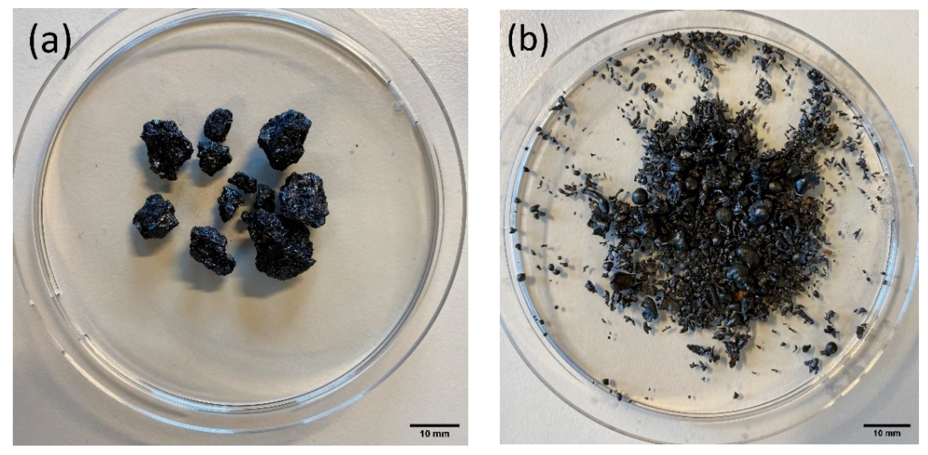
2.1. Sample Material
2.2. Analytical Techniques
3. Results and Discussion
3.1. Chemical Composition
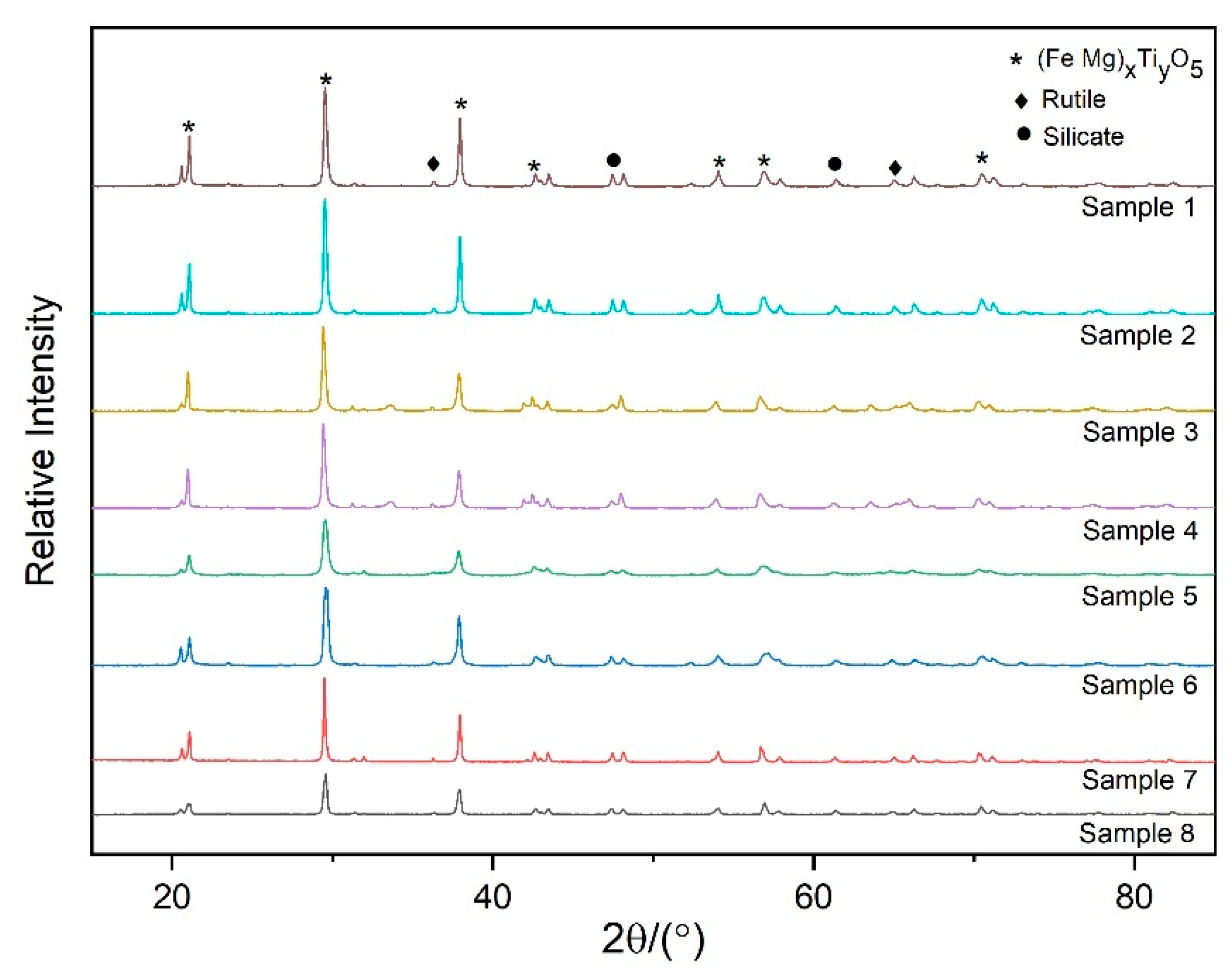
3.2. Phase Analysis
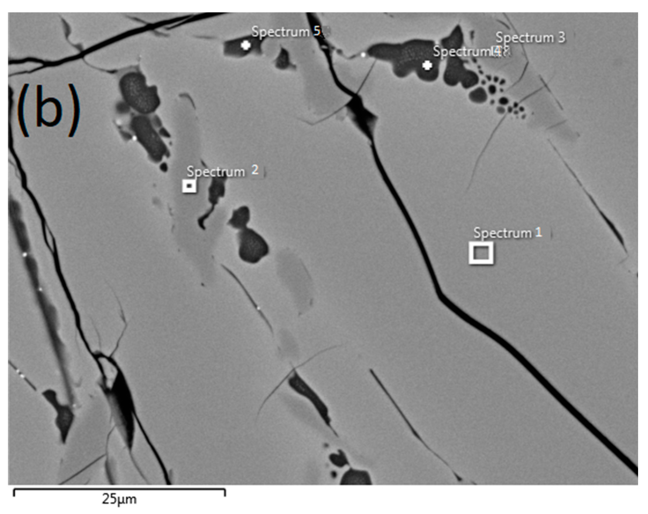
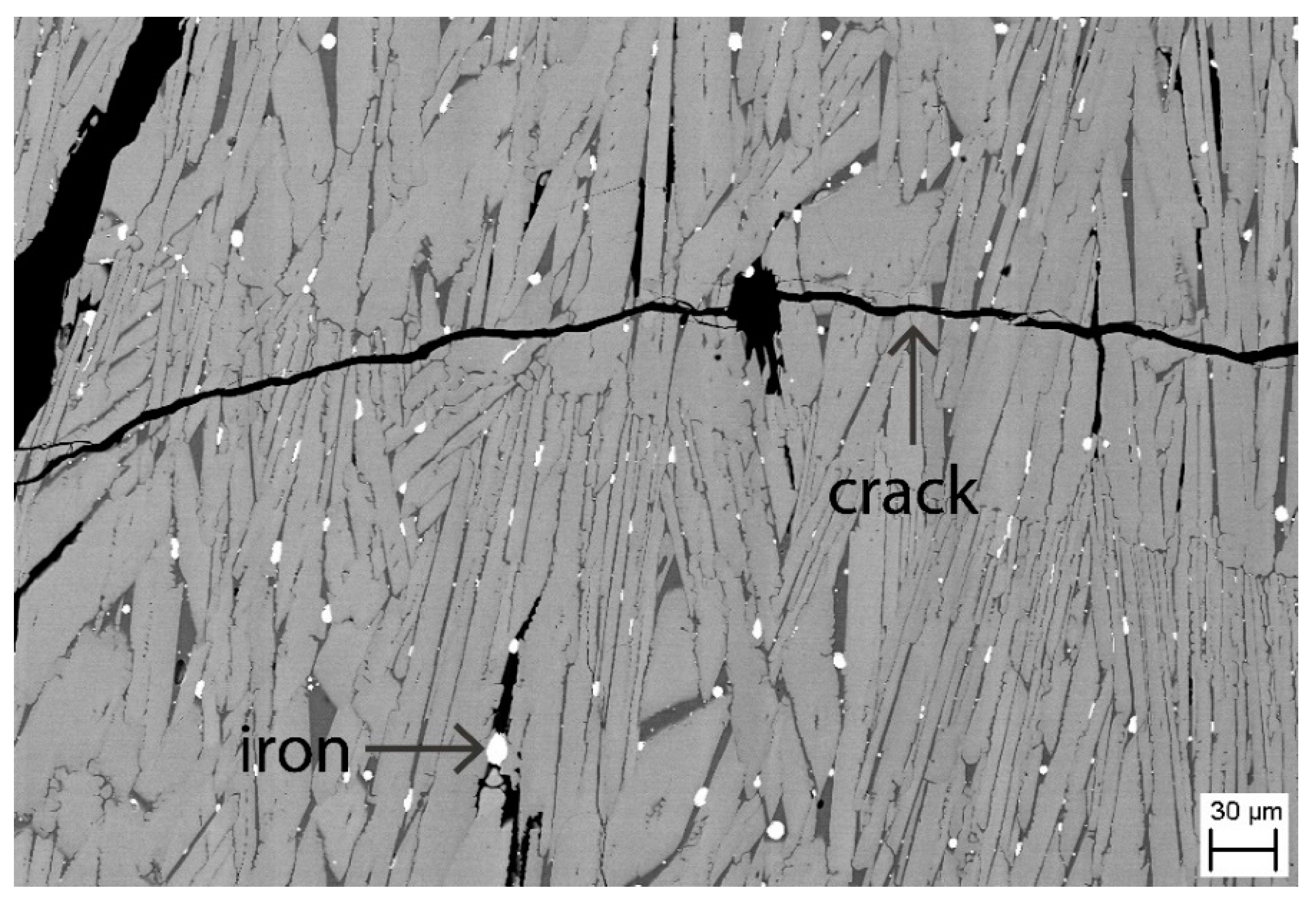
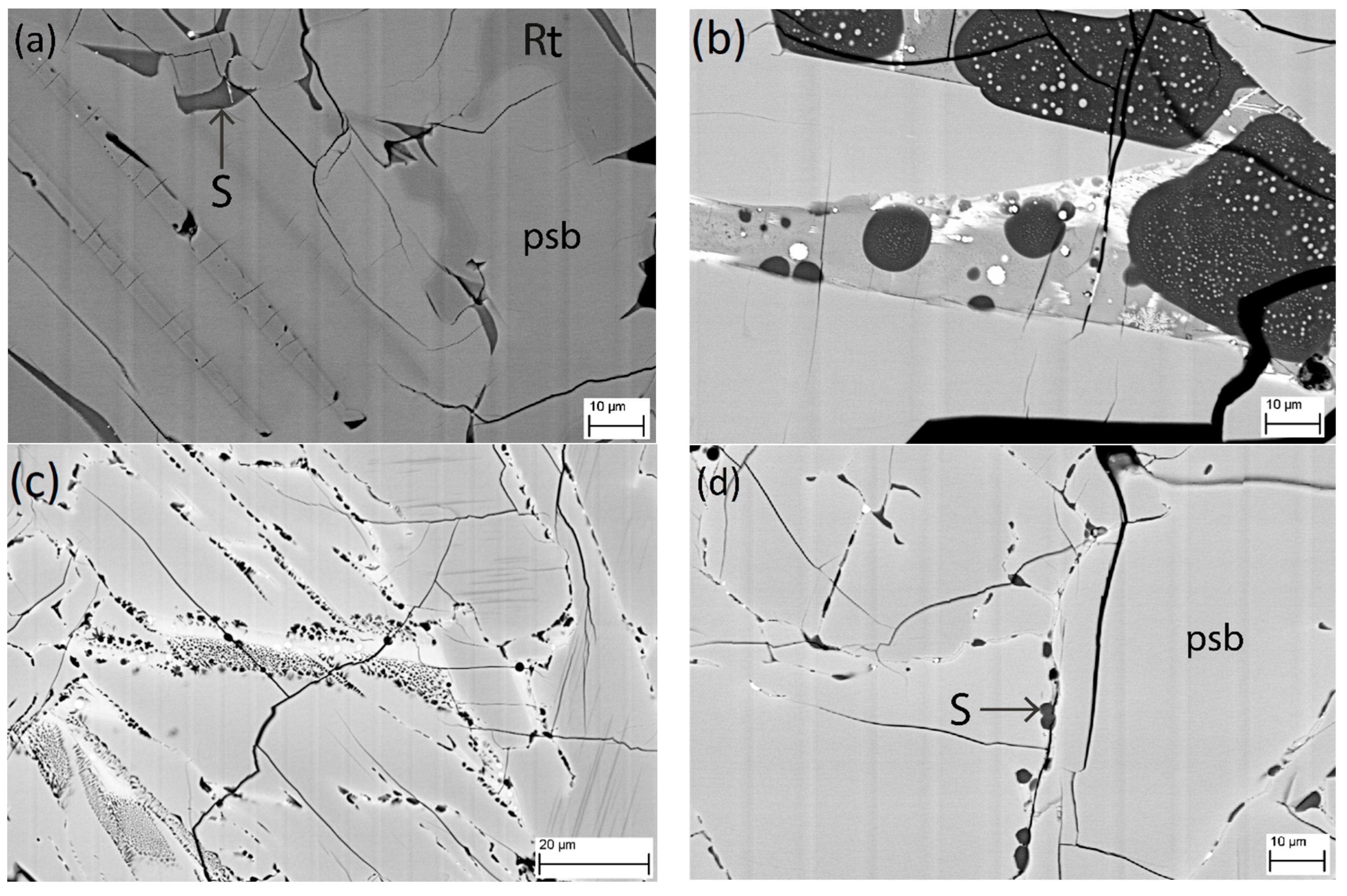
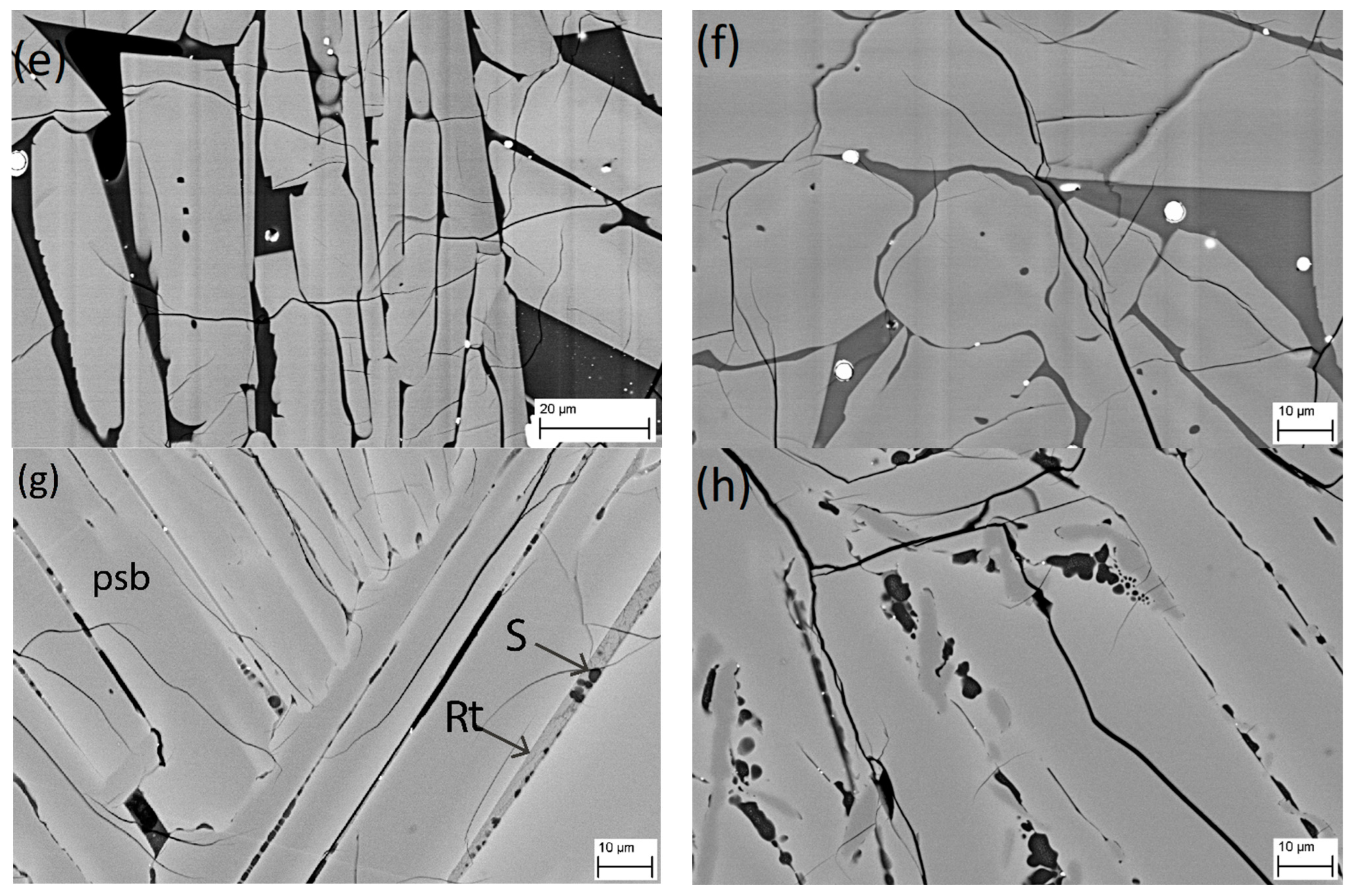
3.3. SEM Analysis
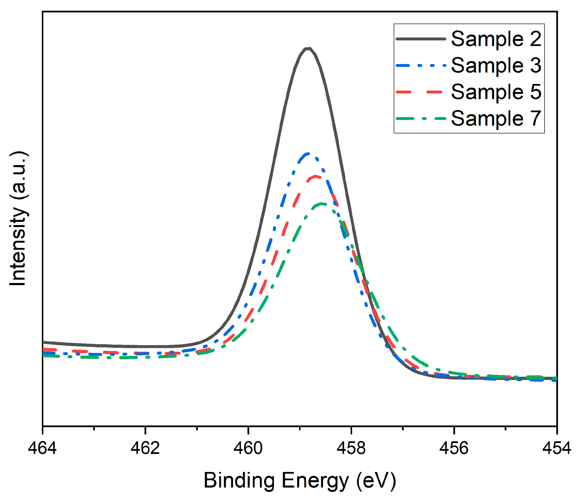
3.4. XPS Analysis
4. Conclusions
Author Contributions
Funding
Data Availability Statement
Acknowledgments
Conflicts of Interest
References
- Mackey, T.S. Upgrading ilmenite into a high-grade synthetic rutile. J. Miner. Met. Mater. Soc. 1994, 46, 59–64. [Google Scholar] [CrossRef]
- Gambogi, J. Titanium Mineral Concentrates; U.S. Geological Survey, Mineral Commodity Summaries, National Minerals Information Center: Lakewood, CA, USA, 2021. [CrossRef]
- Sun, H.; Wang, J.; Dong, X.; Xue, Q. A literature review of titanium slag metallurgical processes. Metal. Int. 2012, 17, 49–56. [Google Scholar] [CrossRef]
- Guo, Y.; Liu, S.; Jiang, T.; Qiu, G.; Chen, F. A process for producing synthetic rutile from Panzhihua titanium slag. Hydrometallurgy 2014, 147–148, 134–141. [Google Scholar] [CrossRef]
- Liu, W.; Lü, L.; Yue, H.; Liang, B.; Li, C. Combined production of synthetic rutile in the sulfate TiO2 process. J. Alloys Compd. 2017, 705, 572–580. [Google Scholar] [CrossRef]
- Ma, N.; Warner, N.A. Smelting reduction of ilmenite by carbon in molten pig iron. Can. Met. Q. 1999, 38, 165–173. [Google Scholar] [CrossRef]
- Pistorius, P.C. Ilmenite smelting: The basics. J. South. Afr. Inst. Min. Metall. 2008, 108, 35–43. [Google Scholar]
- Zietsman, J.H.; Pistorius, P.C. Process mechanisms in ilmenite smelting. SIAMM J. South. Afr. Inst. Min. Metall. 2004, 104, 653–660. [Google Scholar]
- Pistorius, P.C.; De Villiers, J.P.R.; Gräser, P.; Venter, A. Partial slag solidification within ilmenite smelter. Trans. Inst. Min Met. C 2011, 120, 211–217. [Google Scholar] [CrossRef] [Green Version]
- Pistorius, P.C.; Coetzee, C. Physicochemical aspects of titanium slag production and solidification. Met. Mater. Trans. B 2003, 34, 581–588. [Google Scholar] [CrossRef]
- Samal, S.; Mohapatra, B.; Mukherjee, P.; Chatterjee, S. Integrated XRD, EPMA and XRF study of ilmenite and titania slag used in pigment production. J. Alloys Compd. 2009, 474, 484–489. [Google Scholar] [CrossRef]
- Guéguin, M.; Cardarelli, F. Chemistry and Mineralogy of Titania-Rich Slags. Part 1—Hemo-Ilmenite, Sulphate, and Upgraded Titania Slags. Miner. Process. Extr. Met. Rev. 2007, 28, 1–58. [Google Scholar] [CrossRef]
- Fan, H.; Chen, D.; Liu, T.; Duan, H.; Huang, Y.; Long, M.; He, W. Crystallization Behaviors of Anosovite and Silicate Crystals in High CaO and MgO Titanium Slag. Metals 2018, 8, 754. [Google Scholar] [CrossRef] [Green Version]
- Kotzé, H.; Pistorius, P.C. A heat transfer model for high titania slag blocks. J. South. Afr. Inst. Min. Metall. 2010, 110, 57–66. [Google Scholar]
- Bessinger, D.; Beukes, P.; Glenewinkel, R. Granulation of titania slag. In The 6th International Heavy Minerals Conference ‘Back to Basics’; The Southern African Institute of Mining and Metallurgy: Johannesburg, South Africa, 2007; pp. 159–162. [Google Scholar]
- Song, B.; Han, K.; Lv, X. Effect of Cooling Approaches on Chemical Compositions, Phases, and Acidolysis of Panzhihua Titania Slag. Int. J. Mater. Metall. Eng. 2017, 11, 736–741. [Google Scholar]
- Bungu, P.; Pistorius, P. Mineralogy and Initial Chlorination of Water Granulated High Titania Slag. Can. Met. Q. 2009, 48, 45–52. [Google Scholar] [CrossRef]
- De Villiers, J.P.R.; Göske, J.; Tuling, A. Disintegration in high grade titania slags: Low temperature oxidation reactions and associated fracture mechanics of pseudobrookite. Trans. Inst. Min. Metall. Sect. C 2005, 114, 73–79. [Google Scholar] [CrossRef]
- Siebeneck, H.J.; Hasselman, D.P.H.; Cleveland, J.J.; Bradt, R.C. Effects of Grain Size and Microcracking on the Thermal Diffusivity of MgTi2O5. J. Am. Ceram. Soc. 1977, 60, 336–338. [Google Scholar] [CrossRef]
- Pistorius, P.C.; Kotze, H. The Link Between Solidification of High-Titania Slag and Subsequent Comminution. In Proceedings of the VIII International Conference of Molten Slags, Fluxes & Salts, Santiago, Chile, 18–21 January 2009; pp. 51–60. [Google Scholar]
- Siebeneck, H.J.; Hasselman, D.P.H.; Cleveland, J.J.; Bradt, R.C. Effect of Microcracking on the Thermal Diffusivity of Fe2TiO5. J. Am. Ceram. Soc. 1976, 59, 241–244. [Google Scholar] [CrossRef]
- Gupta, A.K.; Aula, M.; Pihlasalo, J.; Mäkelä, P.; Huttula, M.; Fabritius, T. Preparation of Synthetic Titania Slag Relevant to the Industrial Smelting Process Using an Induction Furnace. Appl. Sci. 2021, 11, 1153. [Google Scholar] [CrossRef]
- Pistorius, P.C.; Kotzé, H. Role of silicate phases during comminution of titania slag. Miner. Eng. 2009, 22, 182–189. [Google Scholar] [CrossRef]
- Stefanov, P.; Shipochka, M.; Stefchev, P.; Raicheva, Z.; Lazarova, V.; Spassov, L. XPS characterization of TiO2layers deposited on quartz plates. J. Phys. Conf. Ser. 2008, 100, 012039. [Google Scholar] [CrossRef] [Green Version]
- Wang, Y.; Sun, H.; Tan, S.; Feng, H.; Cheng, Z.; Zhao, J.; Zhao, A.; Wang, B.; Luo, Y.; Yang, J.; et al. Role of point defects on the reactivity of reconstructed anatase titanium dioxide (001) surface. Nat. Commun. 2013, 4, 2214. [Google Scholar] [CrossRef] [PubMed]


| Sample | Weight Percentage of Each Component | Total | ||||||
|---|---|---|---|---|---|---|---|---|
| TiO2 | Ti2O3 | FeO | MgO | SiO2 | MnO | Al2O3 | ||
| 1 | 63.7 | 13.7 | 8.0 | 8.6 | 1.4 | 1.7 | 2.9 | 100 |
| 2 | 60.8 | 20.7 | 11.9 | 1.9 | 1.1 | 1.6 | 2.1 | 100 |
| 3 | 66.0 | 17.0 | 11.6 | 1.1 | 1.2 | 1.3 | 1.8 | 100 |
| 4 | 52.6 | 34.7 | 7.1 | 1.1 | 1.2 | 1.2 | 2.1 | 100 |
| 5 | 56.4 | 23.6 | 4.1 | 7.2 | 2.6 | 1.5 | 4.6 | 100 |
| 6 | 57.1 | 22.8 | 4.3 | 7.1 | 2.7 | 1.5 | 4.5 | 100 |
| 7 | 59.4 | 15.8 | 14.0 | 5.4 | 2.2 | 0.3 | 2.9 | 100 |
| 8 | 60.7 | 22.5 | 7.4 | 4.9 | 1.9 | 0.6 | 2.0 | 100 |
| Sample | Weight Percentage of Each Component | Total | |||||
|---|---|---|---|---|---|---|---|
| TiO2 (Eq.) | FeO | MgO | SiO2 | MnO | Al2O3 | ||
| 1 | 76.9 | 9.4 | 7.2 | 2.1 | 1.5 | 2.9 | 100 |
| 2 | 81.9 | 10.6 | 1.9 | 2.0 | 1.5 | 2.1 | 100 |
| 3 | 86.9 | 7.2 | 1.2 | 1.8 | 1.3 | 1.6 | 100 |
| 4 | 87.0 | 7.1 | 1.2 | 1.8 | 1.3 | 1.6 | 100 |
| 5 | 76.5 | 6.1 | 8.1 | 3.4 | 1.5 | 4.4 | 100 |
| 6 | 76.5 | 6.0 | 8.1 | 3.5 | 1.5 | 4.4 | 100 |
| 7 | 74.0 | 15.3 | 4.4 | 3.6 | 0.4 | 2.3 | 100 |
| 8 | 81.5 | 8.5 | 4.5 | 3.2 | 0.6 | 1.7 | 100 |
| Slag Sample | Phases (wt%) | Total | ||||
|---|---|---|---|---|---|---|
| Pseudo-Brookite | Silicate | Rutile | Anatase | Iron | ||
| 1 | 89.9 | 4.5 | 5.5 | 100 | ||
| 2 | 89.1 | 10.9 | 100 | |||
| 3 | 84.9 | 5.1 | 7.0 | 3.0 | 100 | |
| 4 | 84.0 | 5.0 | 8.3 | 2.7 | 100 | |
| 5 | 93.0 | 7.0 | 100 | |||
| 6 | 86.1 | 13.9 | 100 | |||
| 7 | 88.2 | 11.5 | 0.3 | 100 | ||
| 8 | 84.8 | 12.3 | 2.9 | 100 | ||
| Element | Composition | ||||
|---|---|---|---|---|---|
| Spectrum 1 | Spectrum 2 | Spectrum 3 | Spectrum 4 | Spectrum 5 | |
| O | 37.70 | 39.89 | 40.13 | 48.25 | 47.07 |
| Mg | 3.78 | 0.79 | 0.76 | ||
| Al | 1.02 | 3.09 | 2.99 | ||
| Si | 24.78 | 23.66 | |||
| Ti | 52.95 | 60.11 | 59.87 | 15.87 | 19.18 |
| Mn | 1.43 | 1.27 | |||
| Fe | 4.55 | 5.80 | 5.09 | ||
| Total | 100 | 100 | 100 | 100 | 100 |
| Sample Type | Sample | Binding Energy (eV) | FWHM (eV) |
|---|---|---|---|
| Ti 2p3/2 | Ti 2p3/2 | ||
| Ladle cooled | 2 | 458.82 | 1.70 |
| Granular | 3 | 458.79 | 1.72 |
| Dip rod | 5 | 458.66 | 1.82 |
| Laboratory | 7 | 458.54 | 1.88 |
Publisher’s Note: MDPI stays neutral with regard to jurisdictional claims in published maps and institutional affiliations. |
© 2022 by the authors. Licensee MDPI, Basel, Switzerland. This article is an open access article distributed under the terms and conditions of the Creative Commons Attribution (CC BY) license (https://creativecommons.org/licenses/by/4.0/).
Share and Cite
Gupta, A.K.; Aula, M.; Sreenivasan, H.; Mäkelä, P.; Huttula, M.; Fabritius, T. Study of Synthetic Titania Slags Demonstrating Characteristics Similar to High Titania Ilmenite Slag. Minerals 2022, 12, 386. https://doi.org/10.3390/min12030386
Gupta AK, Aula M, Sreenivasan H, Mäkelä P, Huttula M, Fabritius T. Study of Synthetic Titania Slags Demonstrating Characteristics Similar to High Titania Ilmenite Slag. Minerals. 2022; 12(3):386. https://doi.org/10.3390/min12030386
Chicago/Turabian StyleGupta, Avishek Kumar, Matti Aula, Harisankar Sreenivasan, Pasi Mäkelä, Marko Huttula, and Timo Fabritius. 2022. "Study of Synthetic Titania Slags Demonstrating Characteristics Similar to High Titania Ilmenite Slag" Minerals 12, no. 3: 386. https://doi.org/10.3390/min12030386
APA StyleGupta, A. K., Aula, M., Sreenivasan, H., Mäkelä, P., Huttula, M., & Fabritius, T. (2022). Study of Synthetic Titania Slags Demonstrating Characteristics Similar to High Titania Ilmenite Slag. Minerals, 12(3), 386. https://doi.org/10.3390/min12030386