Article

Experimental Study on Mechanical Properties of Paste Backfill with Flue-Gas Desulphurisation Gypsum under Combined Action of Dry–Wet Cycles and Chloride Erosion

State Key Laboratory of Mine Disaster Prevention and Control, Shandong University of Science and Technology, Qingdao 266590, China
*
Author to whom correspondence should be addressed.
Minerals 2021, 11(8), 882; https://doi.org/10.3390/min11080882
Submission received: 14 July 2021 / Revised: 9 August 2021 / Accepted: 13 August 2021 / Published: 15 August 2021

Abstract

:
Flue-gas desulphurisation gypsum—a solid waste from power plants—can be used to prepare paste backfill for reducing costs. Most paste backfills are exposed to dry–wet cycles and chloride salt-rich water in mines. Therefore, the mechanical properties and damage mechanisms of paste backfill with desulphurised gypsum under the coupling action of erosion due to chloride with different concentrations and dry–wet cycles were investigated using methods such as visual observation, mass measurement, uniaxial compression, acoustic emission, Fourier-transform infrared spectroscopy, X-ray diffraction analysis, and field-emission scanning electron microscopy. With an increasing number of dry–wet cycles, the mass, elastic modulus, and strength of the paste backfill exhibited the trend of increasing first and then decreasing. The failure mechanism changed from mainly vertical fractures to the alternating development of vertical and horizontal fractures. The surface denudation effect of the specimens in a solution with a higher concentration was more severe under the same number of dry–wet cycles. In this study, the laws governing the mass change, strength change, degree of surface denudation, and failure pattern of desulphurised gypsum-filled specimens under different concentrations of chloride salt and different numbers of dry–wet cycles were derived.

1. Introduction

Mining with backfilling has been adopted by many mines because of the ability to control mine subsidence and reduce ecological damage [1,2], but the cost of filling restricts its widespread application. Paste backfill is widely used in coal mines as one of the main materials for filling voids [3]. However, problems such as the gradual reduction in filling materials and high prices have severely limited the application of paste filling in coal mines. There is an urgent need to find a filling material that is inexpensive, widely available, and satisfies all requirements.
Filling materials have been investigated by scholars worldwide. Feng et al. [4] examined the effect of construction waste used as a coarse aggregate in filling paste. Chen et al. [5] studied various mechanical properties of red mud after it was added to filling paste using macroscopic and mesoscopic test methods, and the results provided a basis for the reasonable use of red mud. Li et al. [6] added kaolin to filling paste and studied its mechanical properties and failure characteristics. Cheng et al. [7] studied the effect of coarse aggregate gradation on the yield stress of the filling paste, proposed a paste stability coefficient to characterise the paste gradation, and found that a slurry with a large paste stability coefficient has a compact and stable honeycomb structure that allows the paste to overcome the relatively high yield stress. Fall et al. [8] investigated the strength and microscopic changes of the filling body with Portland cement as a cementing agent under the coupled effects of sulphate and temperature. Liu et al. [9] revealed the influence of the gangue particle size on the compressive strength of specimens and summarised the mechanism of solidification of heavy metals inside the raw materials through gangue-based cementitious filling materials. Zhang et al. [10] studied the mesoscopic structural failure characteristics of a crushed gangue filling material and revealed the impact mechanism of the compression deformation of granular filling materials under loading.
The aforementioned studies provided a variety of filling materials for coal mining. Gypsum can be added to the filling paste system to stimulate the activity of fly ash. Additionally, coal-fired power plants produce a large amount of desulphurised gypsum in the process of flue-gas desulphurisation. After simple dichlorination, the desulphurised gypsum can be added to the filling paste instead of natural gypsum [11], which reduces the cost of the filling paste while disposing the industrial waste generated by coal-fired power plants. Chandar [12] and Hou et al. [13] experimentally verified the possibility of replacing natural gypsum with desulphurised gypsum. Tzouvala et al. [14] demonstrated that desulphurised gypsum can prolong the setting time and increase the strength of cement by comparing desulphurised gypsum with natural gypsum experimentally. Colak et al. [15] studied a composite gel material prepared with cement and desulphurised gypsum and found that the desulphurised gypsum significantly increased the strength of the material. Guo et al. [16,17] confirmed the reuse value of desulphurised gypsum by studying the effects of desulphurised gypsum as an admixture on the mechanical properties and durability of cement. Zhang et al. [18] studied a waterproof material prepared with fly ash, blast furnace slag, and desulphurised gypsum and proved that desulphurised gypsum could improve the water resistance of the paste. Qiao et al. [19] combined cement, desulphurised gypsum, and fly ash at a certain ratio into a composite gel material with excellent cementitious properties. The studies performed by scholars worldwide prove that filling paste mixed with desulphurised gypsum fulfils all the requirements of mining with filling.
A large amount of mine water exists in the goaf, and there are several ions dissolved in the mine water, among which Cl is abundant [20]. Mine water significantly affects the performance of the filling paste. Zhang et al. [21] found that chloride has a positive effect on the early strength of cement paste. In another study, Zhang et al. [22] synthesised AFt (ettringite) and, using XRD (X-ray diffraction) analysis, thermal analysis, and FTIR (Fourier-transform infrared) spectroscopy, determined that the binding effect of AFt with Cl involved physical adsorption and chemical binding. Ekolu [23] believed that, at high Cl concentrations, AFt can chemically bond with Cl to produce Friedel’s salt. Du et al. [24] studied the erosion and deterioration effects of chloride solutions with different mass fractions on filling paste with different ages. Qiao et al. [25] studied the effects of four cations, i.e., Na+, K+, Mg2+, and Ca2+, on the binding mechanism between Cl and concrete and found that the binding capacity exhibited the following trend: Ca2+ > Mg2+ > Na+ ≈ K+. Farnam et al. [26] studied the effect of Cl on the transport properties of concrete and found that the Friedel’s salt generated by the reaction between the two sealed the concrete pores, degrading the transport properties. Chen et al. [27] studied the effects of different initial Cl concentrations on the early strength of gangue-filled paste and found that an initial Cl concentration of 10% resulted in the highest early strength. Wang et al. [28] found that, when Cl is introduced into cementitious materials, the binding of cementitious materials with Cl can be divided into chemical binding and physical adsorption, where the chemical binding mainly consists of the formation of Friedel’s salt.
The rise and fall of the groundwater level expose the filling paste to a dry–wet cycle environment [29], reducing the strength of the filling paste. Li et al. [30] studied the erosion patterns of Cl on cementitious composite materials under dry–wet cycles and found that dry–wet cycles increased the erosion rate of Cl. Chen et al. [31] studied the erosion effects of chloride and sulphate on concrete under the action of dry–wet cycles and found that the presence of SO42− in the chloride solution inhibited the formation of Friedel’s salt, and that the presence of Cl in the sulphate solution inhibited the formation of sulphate products such as AFt. Aldaood et al. [32] studied the deterioration of concrete by dry–wet cycles with different gypsum contents and found that the deterioration was most pronounced at a gypsum content of 25%. However, no studies have been performed on the mechanical properties and deterioration of paste backfill with desulphurised gypsum under the coupled effects of dry–wet cycles [33] and chloride erosion [34].
Because the application of new materials must ensure that the filling body can maintain a certain strength under the special environment of chloride salt erosion and dry–wet cycles, a filling with a uniaxial compressive strength of >2 MPa is typically considered to satisfy the requirements of filling mining. Thus, paste backfill with desulphurised gypsum was prepared in this study. Methods such as appearance analysis, mass determination, uniaxial compression, AE (acoustic emission), and other mesoscopic analysis techniques, including FTIR spectroscopy, XRD analysis, and FE-SEM (field-emission scanning electron microscopy), were used to analyse the changes in the paste backfill with desulphurised gypsum in terms of the appearance, mass, uniaxial compression, elastic modulus, and fracture development of desulphurisation under dry–wet cycles in solutions of different concentrations. The results revealed the mechanical properties and damage mechanisms of paste backfill with desulphurised gypsum under the coupled effects of erosion due to chloride at different concentrations and dry–wet cycles. The study verifies whether the strength of the filling-paste sample in this special environment can still meet the strength required by filling mining. As the lack of filling materials is a global problem, this paper presents the changes in the mechanical properties of desulphurised gypsum as a filling material in the special environment of underground mining, providing theoretical support for the application of desulphurised gypsum in paste filling. Therefore, this research has practical significance and reference value.

2. Test Materials and Methodology

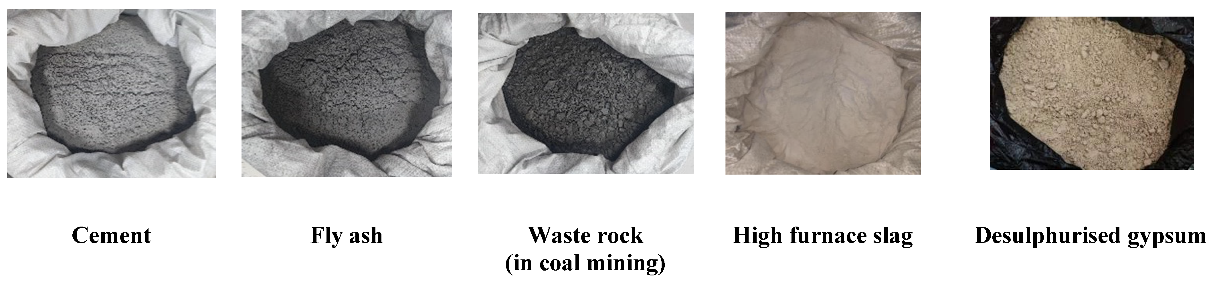
2.1. Specimen Preparation

Blast furnace slag is usually added as an admixture to help gypsum increase the strength of the paste backfill [35], and its optimum ratio was selected for the preparation of paste backfill with desulphurised gypsum in accordance with a related study performed by Jiang [36]. The paste backfills were mainly prepared using cement, fly ash, coal gangue, blast furnace slag, desulphurised gypsum, and water. Grade 32.5 ordinary silicate cement, produced by Shandong Rizhao No. 3 Cement Plant, was used in the test. Fly ash and desulphurised gypsum were taken from the Zoucheng Power Plant of Huadian Power International in the Shandong Province. The coal gangue was taken from the Daizhuang coal mine after secondary crushing. The granulated blast furnace slag used in the test was obtained from Qingdao Special Steel Co. The composition of the raw materials was determined via X-ray fluorescence spectroscopy (Panalytical Axios FAST, Malvern, UK), and the main chemical compositions of the raw materials are listed in Table 1. The morphologies of the raw materials are shown in Figure 1.
The fraction of raw materials used in the test was cement/gangue/admixture = 1:6:4, where the admixture ratio was fly ash/blast furnace slag/gypsum = 12:3:1. Thirty-nine paste backfills with desulphurised gypsum were prepared with this ratio, of which three specimens (the control group) were not subjected to dry–wet cycles.
The mass fraction for all the above solids was 78%, and the maximum particle size of the coal gangue was 25 mm. The preparation process was as follows: first, the raw materials were weighed using an electronic scale and placed in NJ-160 Agitator in accordance with the above ratio for stirring and mixing. After complete mixing, water was added and continued stirring until it became a paste filling body with certain fluidity Then, the prepared filling paste was poured into a 70.7 mm × 70.7 mm × 70.7 mm cube mould. By manual vibration and tamping, the bubble entrainment of the sample in the mould was removed. After 24 h, the solidified specimens were demoulded and taken out. The prepared specimens were placed in a box at a constant temperature and humidity (temperature of 20 °C and 95% relative humidity) to be maintained for 28 days [37]. Subsequently, the mechanical properties of the specimens were tested using GB/T50107-2010.

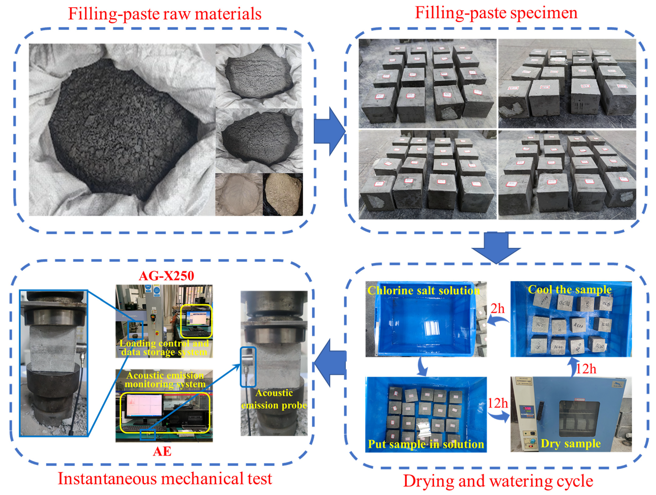
2.2. Test Methodology

Chloride solutions with mass fractions of 3%, 5%, and 10% were prepared. After 28 days of conditioning, the specimens were placed in containers with each of the three solutions. The dry–wet cycles were simulated by immersing the specimen for 12 h, followed by 12 h of drying in an oven at 60 °C [38]. The specimens were divided into four groups and subjected to five, 10, 15, and 20 dry–wet cycles. The number of dry–wet cycles was labelled as 1, 2, 3, and 4, and the concentration of the solutions was labelled as 3, 5, and 10. For example, the specimen subjected to three dry–wet cycles in a solution with a 3% mass fraction was labelled as C13. This nomenclature was used for all the specimens. The masses of the specimens before and after the test were weighed and recorded using an electronic scale with a precision of 0.01 g. The mechanical properties of the specimens at the end of the dry–wet cycles were tested using a Shimadzu AG-X250 (Shimadzu, Kyoto, Japan) electronic universal tester with a loading rate of 0.01 mm/s. The uniaxial compression failure process was monitored in real time using an AE test system (MISTRAS PCI-2 Series, Physical Acoustics, Princeton, NJ, USA). Figure 2 shows the procedure for the mechanical test. The main amplification was set as 40 dB, the threshold was 45 dB, the floating threshold was 6 dB, the probe harmonic frequency was 100–600 kHz, and the sampling frequency was 106 times/s. Vaseline was applied between the sensor and the specimen for coupling to reduce the acoustic impedance difference at the contact surface and the reflection-induced loss of energy at this interface to ensure that the AE signal was well received by the sensor. A FTIR instrument (Nicolet iS5, Thermo Fisher Scientific, Waltham, MA, USA) was used to identify the surface functional groups of the specimen samples, and a total of 50 scans were taken to obtain the infrared spectra. Crystal calibration was performed on the specimen powders using a X-ray diffractometer (Bruker D8 advance, Bruker, Billerica, MA, USA) with a diffraction-angle range of 5–90° and a scan step of 8 °/min. The mesostructures of the bulk specimens of backfill paste were scanned using FE-SEM (Apreo S Hivac, Thermo Fisher Scientific, Waltham, MA, USA) with resolutions of 5000×, 10,000×, and 40,000×. The samples were sprayed with gold before the scanning.

3. Mechanical Performance Tests

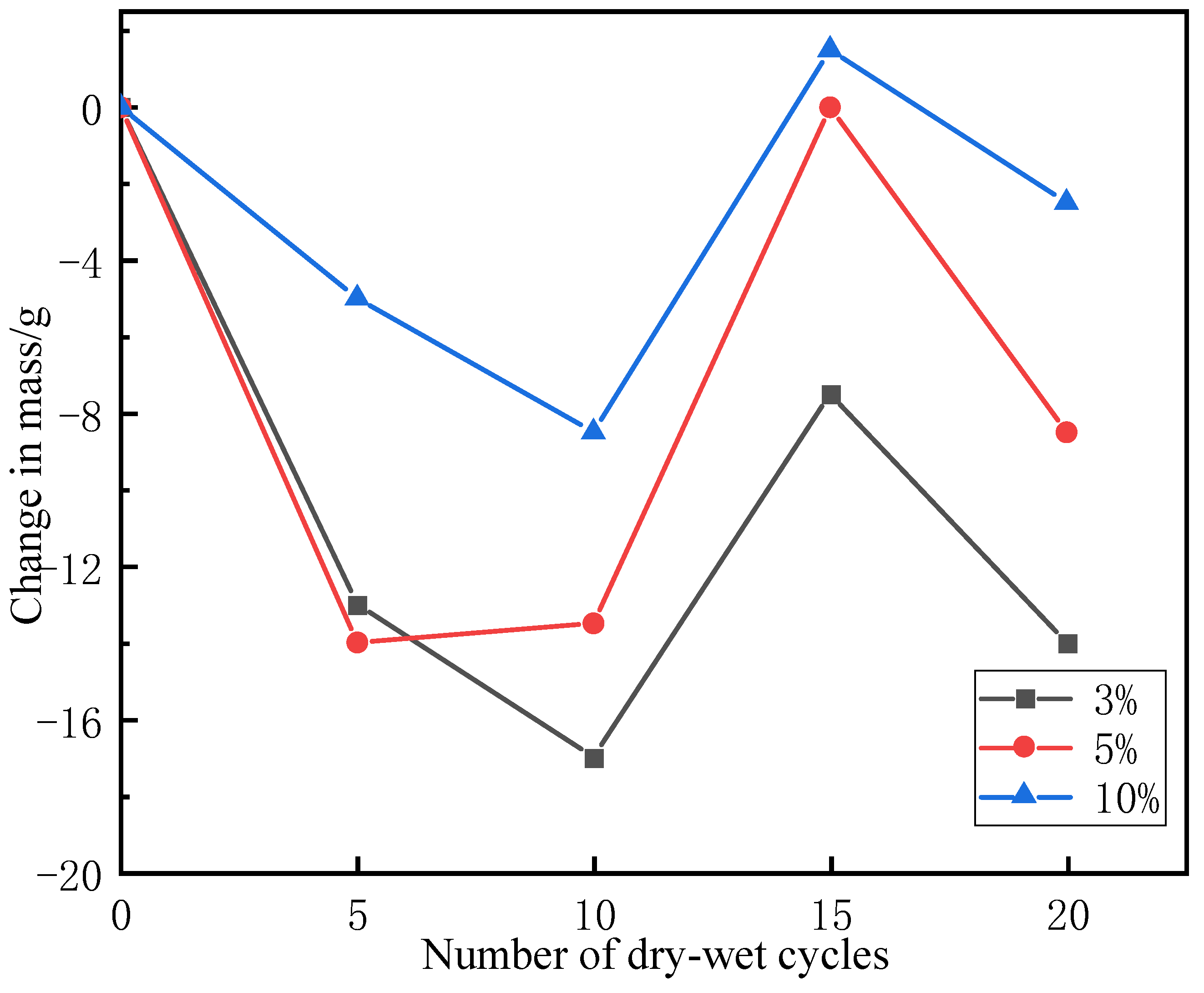
3.1. Effects of Dry–Wet Cycles Coupled with Chloride on Masses of Filled Specimens

The most apparent effects of dry–wet cycles on the paste backfills with desulphurised gypsum were the effects on their appearance and mass. The changes of the surfaces of the specimens in 3%, 5%, and 10% chloride solutions for five, 10, 15, and 20 dry–wet cycles are shown in Figure 3, and the mass changes are shown in Figure 4.
Gangue was used as a coarse aggregate in the preparation of the filling paste. The surface denudation effect under the coupled effects of dry–wet cycles and chloride erosion of the specimen led to the appearance of gangue on the specimen surface (observed as black spots). The area of gangue on the specimen surface can be used to evaluate the degree of deterioration of the specimen. As shown in Figure 3, gangue only appeared after 20 dry–wet cycles in the solution with a 3% concentration; gangue appeared after 15 and 20 dry–wet cycles in the solution with a 5% concentration, whereas the appearance of gangue started from the 10th dry–wet cycle in the solution with a 10% concentration. The surface denudation of the specimen was particularly exacerbated with the increasing number of dry–wet cycles. The area of black gangue was increasingly large at the edges and corners of the specimens, where passivation gradually occurred under the denudation effect. With an increase in the solution concentration, the surface denudation of the specimen was exacerbated, and the number of revealed gangue particles on the specimen surface gradually increased. This indicates that both the concentration of the chloride solution and the number of dry–wet cycles were positively correlated with the degree of surface denudation of the specimens. In addition to the deterioration of the specimen surface due to the dry–wet cycles, the Cl in the solution reacted with the dense AFt on the specimen surface to form insoluble Friedel’s salt, which exacerbated the denudation of the specimen surface.
Figure 4 presents the relationship between the mass of the backfill sample and the number of dry–wet cycles at different concentrations. Here, the mass of the backfill without dry–wet cycles was labelled as 0, and the mass variation of the backfill after dry–wet cycles was plotted as a broken line chart. As shown, the mass changes for the filled specimens in 3%, 5%, and 10% chloride salt solutions all exhibited a pattern of decreasing, increasing, and then decreasing again. At the fifth and 10th dry–wet cycles, the masses of the specimens exhibited substantial reductions; the specimen in the 3% solution exhibited the largest mass loss (13.5 g). The components of the specimens that were not involved in the hydration reaction dissolved into the solution, while the loosely bound water in the sample evaporated in the drying phase of the dry–wet cycles, leading to a rapid decline in the masses of the specimens at the beginning of the dry–wet cycles. As the number of cycles increased, the masses of the specimens also began to increase, and, by the 15th dry–wet cycle, the masses of the specimens reached their maximum value. The specimen in the 10% solution exhibited the largest mass increase; it was 1.5 g heavier than the specimens not subjected to dry–wet cycles. During this process, the hydration inside the specimen proceeded further, and the free water in the solution solidified into bounded water inside the specimen, while the chlorine ions in the chloride salt solution and the specimens underwent a new hydration reaction. This new reaction filled the voids inside the specimens and improved the compactness of the specimens, increasing the masses of the specimens. lastly, the masses of the specimens began to decrease when the hydration reaction inside the specimens approached completion, and Cl reacted with the hydration products in the specimens to form Friedel’s salt. The overall structure of Friedel’s salt was looser than that of the hydration products; thus, the combined effects of the dry–wet cycles and chloride erosion led to the deterioration of the overall structures of the specimens. This resulted in the denudation of the surface layer and the loosening of the internal structures of the specimens, causing a reduction in mass.
Under the dry–wet cycles, the 3% chlorine salt solution had the most severe deterioration effect on the specimens (with the largest mass loss), followed by the 5% and 10% solutions. This is mainly because Cl at a high concentration can penetrate the specimen rapidly and activate fly ash inside the specimen [21], which accelerates the hydration reaction inside the specimen. Furthermore, the high concentration of Cl can maintain the Friedel’s salt in the specimen and the chloride salt precipitated through the pores inside the specimen during the dry–wet cycles. This reduced the deterioration effect of the dry–wet cycles on the masses of the specimens. The continuation of hydration reaction inside the specimen is the main factor for the mass growth of the specimen. In the specimen with low concentration solution, the velocity of Cl entering the specimen was low, and the degree of hydration reaction inside the specimen was low, leading to serious mass loss of the specimen. When the number of drying and wetting cycle was 15 or 20, the hydration reaction inside the specimen was complete, and Cl reacted with hydration products to generate Friedel’s salt. However, the low concentration of solution concentration was not enough to maintain the existence of Friedel’s salt, which led to the decomposition of Friedel’s salt inside the specimen and exacerbated the mass loss of the specimen.

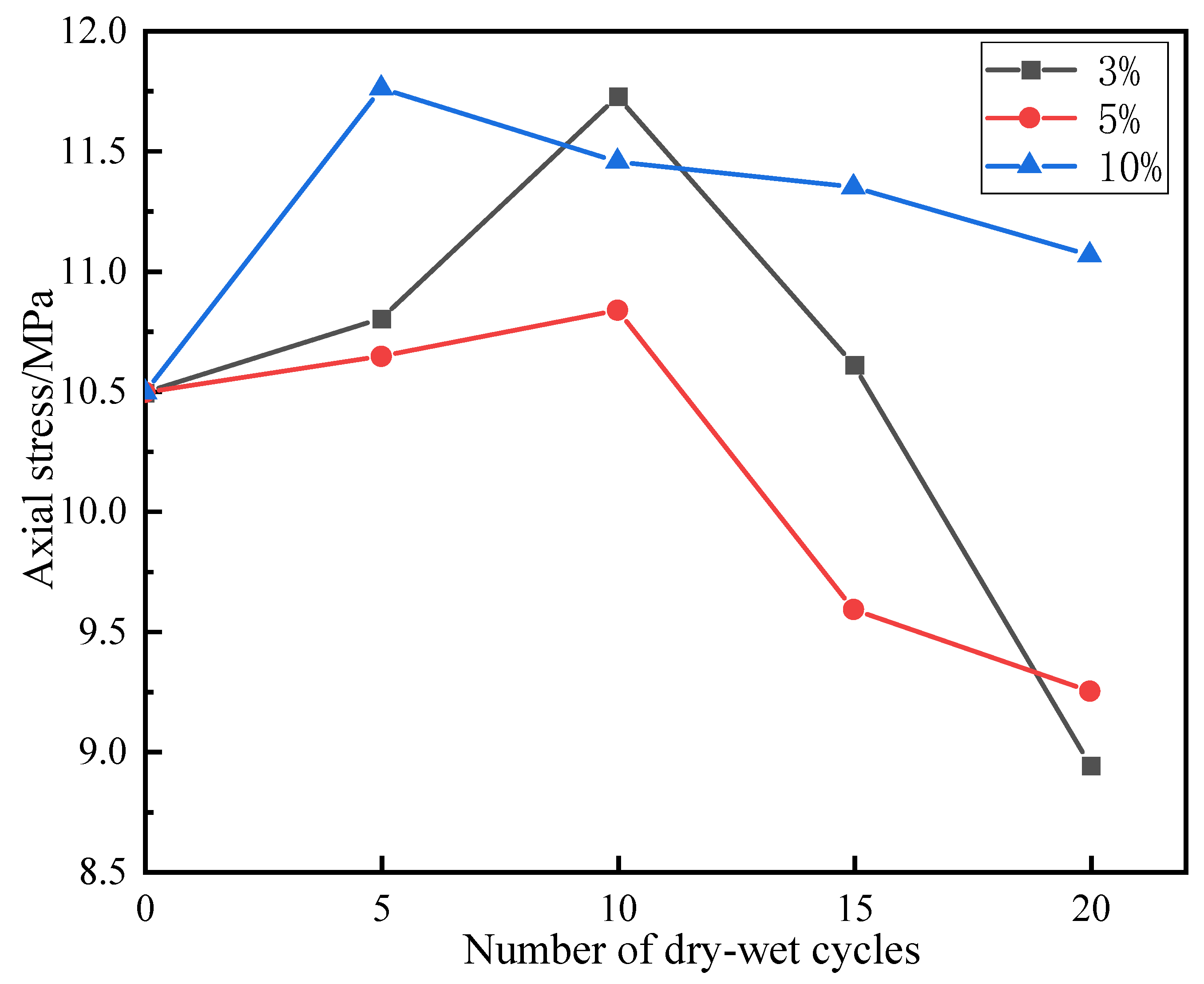
3.2. Effects of Dry–Wet Cycles Coupled with Chloride Salt on Uniaxial Compressive Strengths of Backfill Specimens

Table 2 is Uniaxial strengths of desulphurisation gypsum-filled specimens. Table 3 is Elastic moduli of backfill specimens with desulphurised gypsum. Figure 5 presents the variations in the peak stresses of backfill samples subjected to uniaxial compression under different conditions. As shown, the peak stresses of the specimens under the uniaxial compression conditions for the 3%, 5%, and 10% chloride salt solutions increased slightly and then decreased. At the fifth and 10th dry–wet cycles, there was a slight increase in the strength of the specimen (approximately 12%). This is because the hydration reaction within the specimen was not yet complete, and the strength increase provided time for the hydration reaction within the specimen to continue. The chloride solution also enhanced the strength of the specimen, because the hydration reaction within the specimen was not yet completed at this time. Moreover, Cl can fully interact with the fly ash through diffusion and chemically react with the potential active substances Al2O3 and Ca2+ inside the specimen to generate gel substances such as C–A–H (xCaO·Al2O3·yH2O) [39]. The newly generated substances fill the internal pores of the specimen, increasing its strength. Thus, the specimens exhibited an increase in the peak stress at the beginning of the dry–wet cycles. As the number of dry–wet cycles increased, the peak stress of the specimens began to decrease, and, by the 20th dry–wet cycle, the strength of the specimens was reduced by approximately 15%. This is because the hydration reaction inside the specimens was complete, and the Cl reacted with the non-hydrated active materials and the hydration products inside the specimen to produce Friedel’s salt [40], which is insoluble and tends to swell. These hydration products accumulated and swelled inside the specimens, generating cracks in the specimens. Owing to the physical denudation of the specimens due to the dry–wet cycles, the AFt films generated on the outer surface of the specimens were damaged and peeled off [41]. Thus, Cl could more easily invade the specimen interior and precipitate in the voids, causing fracture enlargement, which further reduced the specimen strength. Therefore, the peak stresses of the specimens exhibited an overall reduction.
The strengths of the specimens in the 10% chloride solution were maximised at the fifth dry–wet cycle (with a 12% increase in strength) and exhibited a decreasing trend as the dry–wet cycles continued. The change in the peak stress was the most moderate at this concentration, with a 5% increase in strength by the 20th cycle. This is because the higher concentration of Cl created a larger concentration gradient within the specimen interior, allowing Cl to enter the interior more quickly during the dry–wet cycles. The peak strength of the specimen was maximised at the fifth dry–wet cycle owing to the enhancement effect of Cl. The specimen strength slowly decreased in the subsequent dry–wet cycles because the high concentration of chloride salt maintained the presence of Friedel’s salt [42,43], preventing the generation of a large number of fractures inside the specimen due to the decomposition of the Friedel’s salt. Simultaneously, the components of the solution continued to precipitate within the pores inside the specimens, filling the fractures. This eventually reduced the specimen strength, although the reduction rate was lower. The specimens in the 3% and 5% chloride solutions reached their maximum peak strengths at the 10th dry–wet cycle. The peak stress then began to decrease, and the reduction rate was significantly higher for the 3% solution (from a 12% increase in strength at the 10th dry–wet cycle to a 15% reduction in strength at the 20th cycle) than for the other two concentrations. This was due to the limited chlorine salt concentration. Although Friedel’s salt was available, the absence of high concentrations of Cl to sustain it inside the specimens resulted in numerous fractures inside the specimens after the decomposition of the Friedel’s salt. The combination of this effect with the deterioration of the specimen strength due to the dry–wet cycles resulted in a sharp decrease in the specimen strength.
Figure 6 presents the changes in the elastic moduli of backfill samples under different conditions. As the number of dry–wet cycles increased, the elastic moduli of the specimens exhibited a trend of first increasing and then decreasing. At the fifth dry–wet cycle, the elastic moduli of the specimens exhibited an increase of approximately 10% for all the solution concentrations. At the 10th dry–wet cycle, the elastic moduli of the specimens continued to increase, with the specimens in the 3% solution exhibiting increases of up to 18%. The hydration reaction in the specimens proceeded further, closing the pores and fractures within the specimens to some extent and resulting in a more compact internal structure. This was eventually reflected by the increasing elastic moduli of the specimens. As the dry–wet cycles continued, the elastic moduli of the specimens all decreased to different degrees, with the specimens in the 3% solution exhibiting the largest reductions (30%). The elastic moduli of the specimens in the 5% solution decreased by 18%, and those of the specimens in the 10% solution decreased by only 3%. This is mainly because the hydration reaction inside the specimens was complete. Friedel’s salt formed by the reaction between Cl and the hydration products led to the deterioration of the internal structure of the backfill. Furthermore, the low concentration of Cl could not maintain the Friedel’s salt, leading to its decomposition. This caused deterioration of the internal structures of the specimens, which was reflected by reductions in the elastic moduli.
The uniaxial compressive strength and elastic modulus of the paste backfill with desulphurised gypsum exhibited an overall pattern of a short increase followed by a sharp decrease under the coupled effects of chloride erosion and dry–wet cycles. Despite the degradation of the specimens due to the chloride erosion and dry–wet cycles, the initial strength of the paste backfills with desulphurised gypsum was as high as 10.49 MPa, and the average strength of the group with the most severe deterioration after the dry–wet cycles reached 8.94 MPa. Thus, desulphurised gypsum can satisfy the strength requirements for application as a filler material in mining with paste backfill.

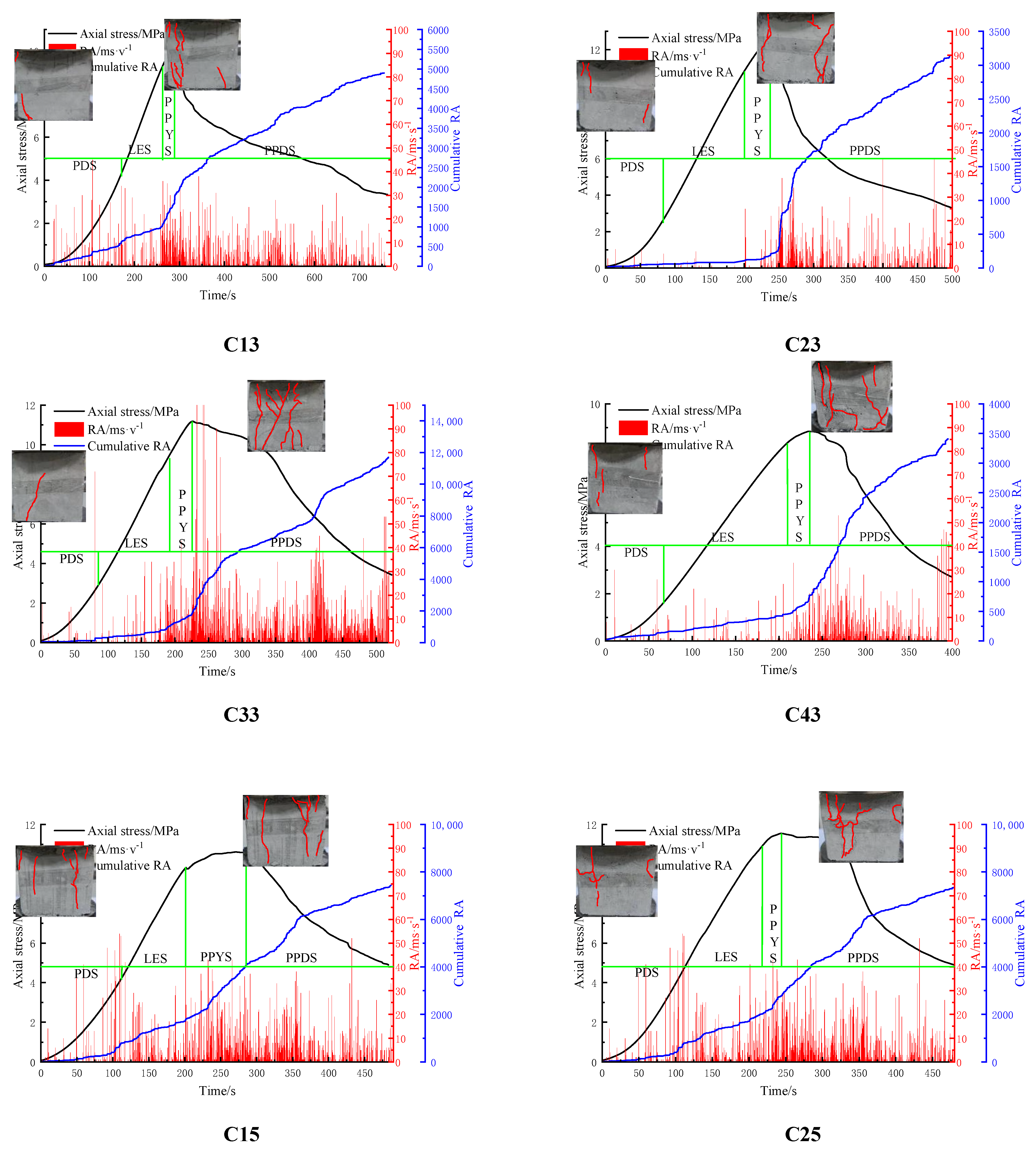
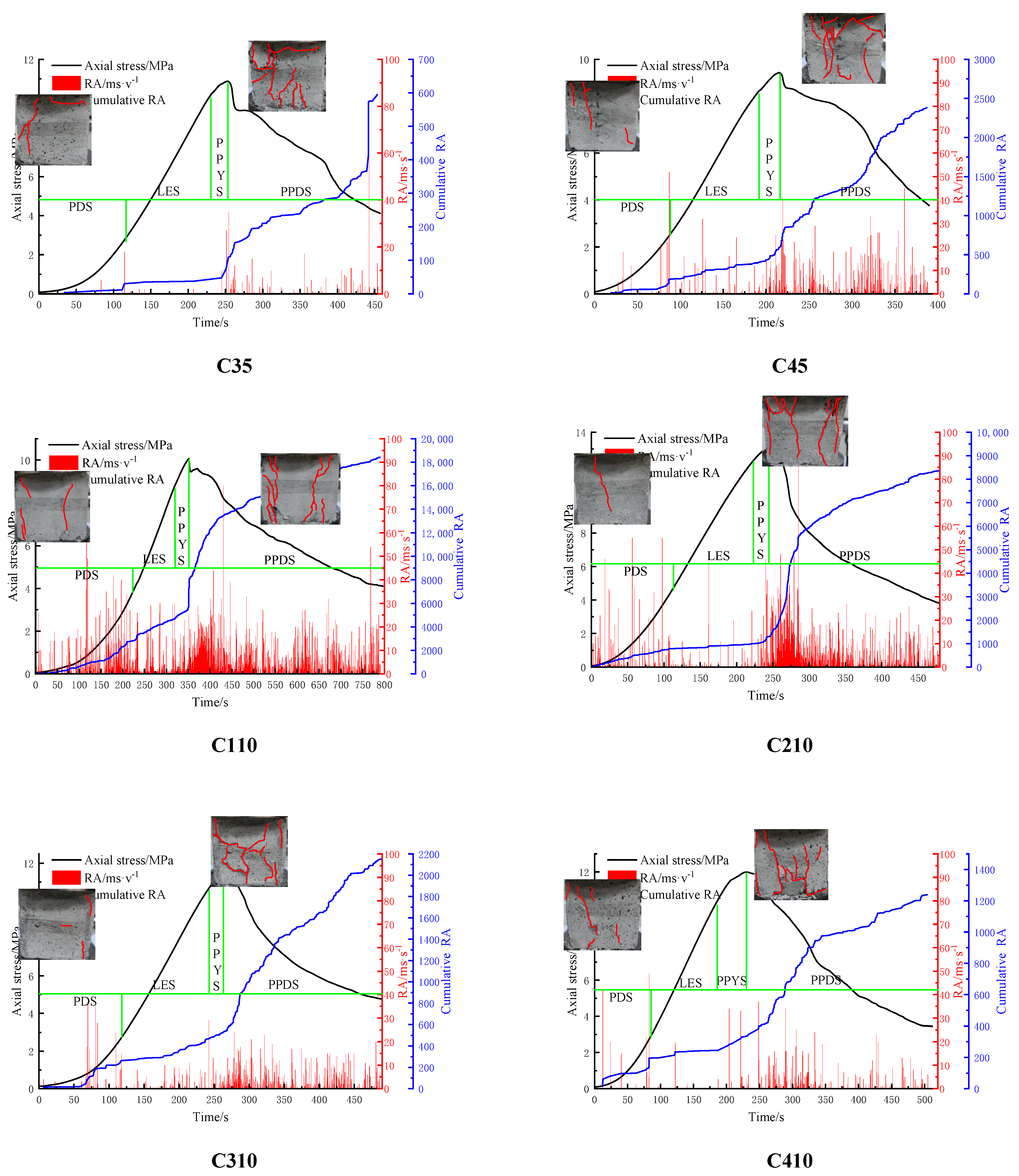
3.3. AE Characteristics

AE (acoustic emission) is often used as a non-destructive monitoring method to analyse the deformation of a specimen during loading or the generation of elastic acoustic waves during fracturing and to, thus, determine the mechanical characteristics of its internal mesostructure [44]. However, the influence of the variables of this test on the unstable failure processes of the specimens mainly affects the initiation, expansion, and penetration processes of microcracks in the specimens during loading by changing their mesostructures, compositions, and other characteristics. The specimens will inevitably have voids during the preparation process. Thus, fissures and weak cementitious surfaces will be produced around the gangue during the hardening process of the specimens, which leads to a variety of macroscopic failure forms, such as tensile failures and shear failures. The AE test results generally indicated a high frequency and low strength, and the fracture development of the specimens was dominated by vertical edge cracks.
Japanese scholars Shiotani et al. [45] calculated the RA (the ratio of rise time to amplitude) value of AE for bending and shear tests on rocks and concluded that low RA values correspond to shear fractures and high RA values correspond to tension fractures. In combination with the uniaxial compression process, AE can be similarly analysed according to the four stages of uniaxial compression. In the first PDS (pressure density stage), more AE signals were generated in the PDS, as the paste backfill differed from the rock specimens; thus, multiple shear failures occurred. Because no external load was applied during the paste preparation, the internal structures of the specimens were relatively loose compared with the rocks, having a large number of internal pores and fractures. Under loading, the internal pores closed, generating acoustic signals. In the subsequent LES (linear elastic deformation stage), the internal pores and fractures in the specimens were closed in the PDS, and the applied load was not sufficient to create new fractures in the specimen; thus, few AE signals were monitored at this stage, and the tension failure was dominant. The internal structures of the specimens were relatively stable. The AE signals had high intensities in the two subsequent stages; thus, shear failure dominated within the specimen. In the PPYS (pre-peak yielding stage), the specimen’s structure underwent massive macroscopic failures as the load increased and new fractures began to form inside the specimen; thus, the AE signals monitored at this stage were strong. In the PPDS (post-peak damage stage), the damage to the overall structure of the filling reduced its load-bearing capacity. A more pronounced deformation also occurred at this stage, and numerous AE signals were generated, accompanied by the macroscopic deformation of the specimen.
Figure 7 presents the macroscopic fracture development and AE monitoring results for the specimens during uniaxial compression. As shown, the RA values measured via AE monitoring of the specimens during uniaxial compression at the fifth and 10th dry–wet cycles were low. The RA values increased suddenly when the specimens reached the peak stress, at which time the vertical fractures dominated the failure processes of the specimens. This indicates that, at the fifth and 10th dry–wet cycles, the specimens had good integrity in the early stage of uniaxial compression and did not have dense fractures. Numerous fractures were produced in the specimens when the peak stresses were reached. From a mesoscopic perspective, this is because the chloride salt enhanced the hydration reaction inside the specimens at the beginning of the dry–wet cycles. The precipitation of chloride salt in the pores inside the specimens led to relatively compact specimens, and the fractures were filled with the hydration products and chloride salt crystals, increasing the brittleness of the specimens. Therefore, few fractures were produced in the early stage of stress application. When the peak stresses of the specimens were reached, numerous fractures were instantaneously produced under the load. At the 15th and 20th dry–wet cycles, the RA values obtained via the AE monitoring of the specimens no longer exhibited large sudden changes but tended to gradually increase in the fracture extension stage, and the uniformity of the increase in the RA values was more obvious at the 20th dry–wet cycle. At this time, the macroscopic fracture development of the specimens mostly involved the combined development of vertical and horizontal fractures. From a mesoscopic perspective, this is because, with the increase in the number of dry–wet cycles, the internal deterioration of the specimens by the coupled effects of chloride salt and dry–wet cycles became increasingly severe. Numerous fractures were generated inside the specimens at this time, which gradually expanded and generated new fractures under the load. This led to an increase in the RA values over time in the stage before the peak stress was reached. Additionally, the internal loosening of the specimens contributed to the simultaneous development of vertical and horizontal fractures. More intense AE signals were detected for the specimens at the 15th and 20th dry–wet cycles than at the fifth and 10th dry–wet cycles, indicating that more fractures were developed in the specimens under the load during the early dry–wet cycles. This is because the original fractures closed by hydration within the specimens were reopened under the load, generating AE signals. The interiors of the specimens were further damaged as the dry–wet cycles progressed. Moreover, the Friedel’s salt formed by the erosion of chloride salt had good swelling properties. Its large accumulation inside the specimens increased the plasticity of the specimens. The enhancement of the plasticity of the specimens reduced the AE signals generated by internal brittle fractures, which eventually led to more AE signals being detected at the fifth and 10th dry–wet cycles than at the 15th and 20th dry–wet cycles. This phenomenon was more prominent for solutions with higher concentrations, because they could maintain the presence of more Friedel’s salt in the specimens, resulting in a higher plasticity.

4. Mesoscopic Tests

The macroscopic mechanical property tests revealed that the effects of the dry–wet cycles with the 5% solution on the mass, mechanical properties, and AE of the paste backfill specimens were between those for the 3% and 10% solutions. Additionally, the dry–wet cycling with the 5% solution did not produce unique phenomena that were not observed for the other groups. Thus, the mesoscopic analysis was only conducted for the specimens in the 3% and 10% solutions. The test equipment is shown in Figure 8.

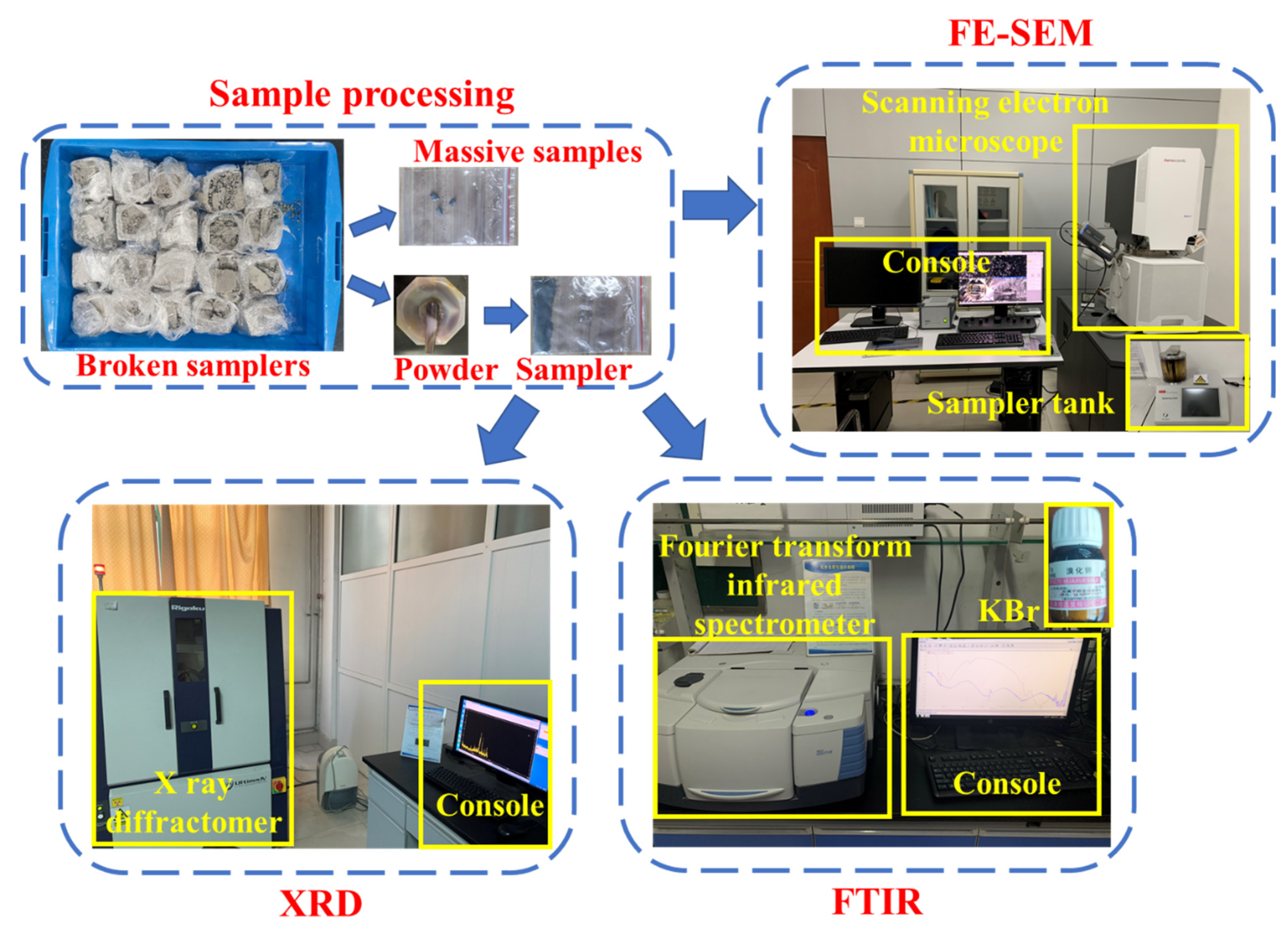
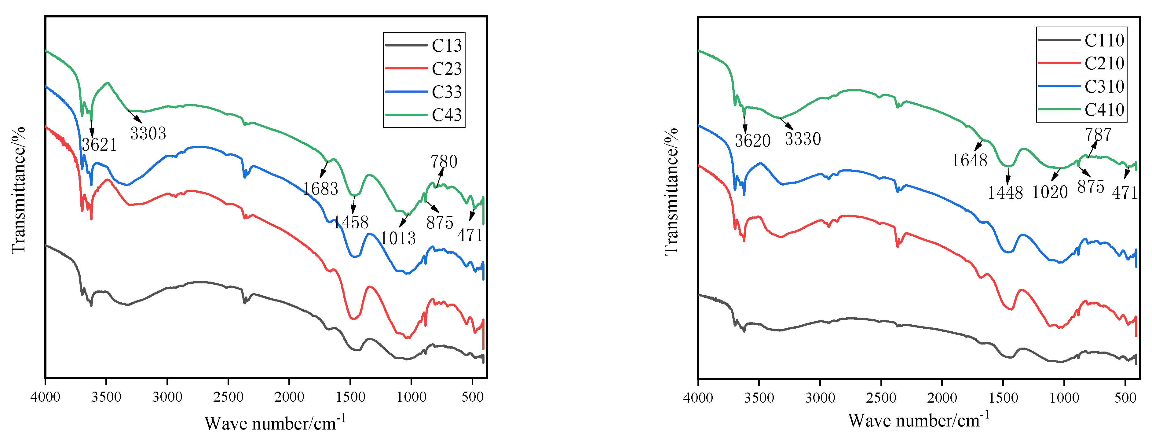
4.1. Analysis of Surface Functional Groups via FTIR Spectroscopy

Figure 9 shows the FTIR spectra of the filled specimens. The absorption peak at 3630 cm−1 corresponded to the O–H stretching vibration of Ca(OH)2. The absorption band at 1683–1648 cm−1 corresponded to the bending vibration of H–O. The absorption band at the 1058–1110 cm−1 corresponded to the asymmetric stretching vibration of S–O. As indicated by the XRD results, these absorption peaks were the vibration peaks of AFt. There was a difference at 780 cm−1, which was attributed to the absorption peak of the reaction that produced Friedel’s salt, according to the XRD analysis. The broad absorption spectrum band at 3303–3330 cm−1 corresponded to the stretching vibration of Si=OH in the C–S–H (xCaO·SiO2·yH2O) gel. The peak at 1448–1458 cm−1 may have been due to the stretching vibration of the C=C absorption band. The weak absorption peak at 875 cm−1 characterises the bending vibration of Si=OH in the C-S-H gel, and that at 471 cm−1 characterises the bending vibration of Si–O–Si in the C–S–H gel. As indicated by the XRD results, the main hydration products were Ca(OH)2, C–S–H, and C–A–H gel, while Ca(OH)2 underwent a chemical reaction with CO2 in the air to produce CaCO3 [27,46].

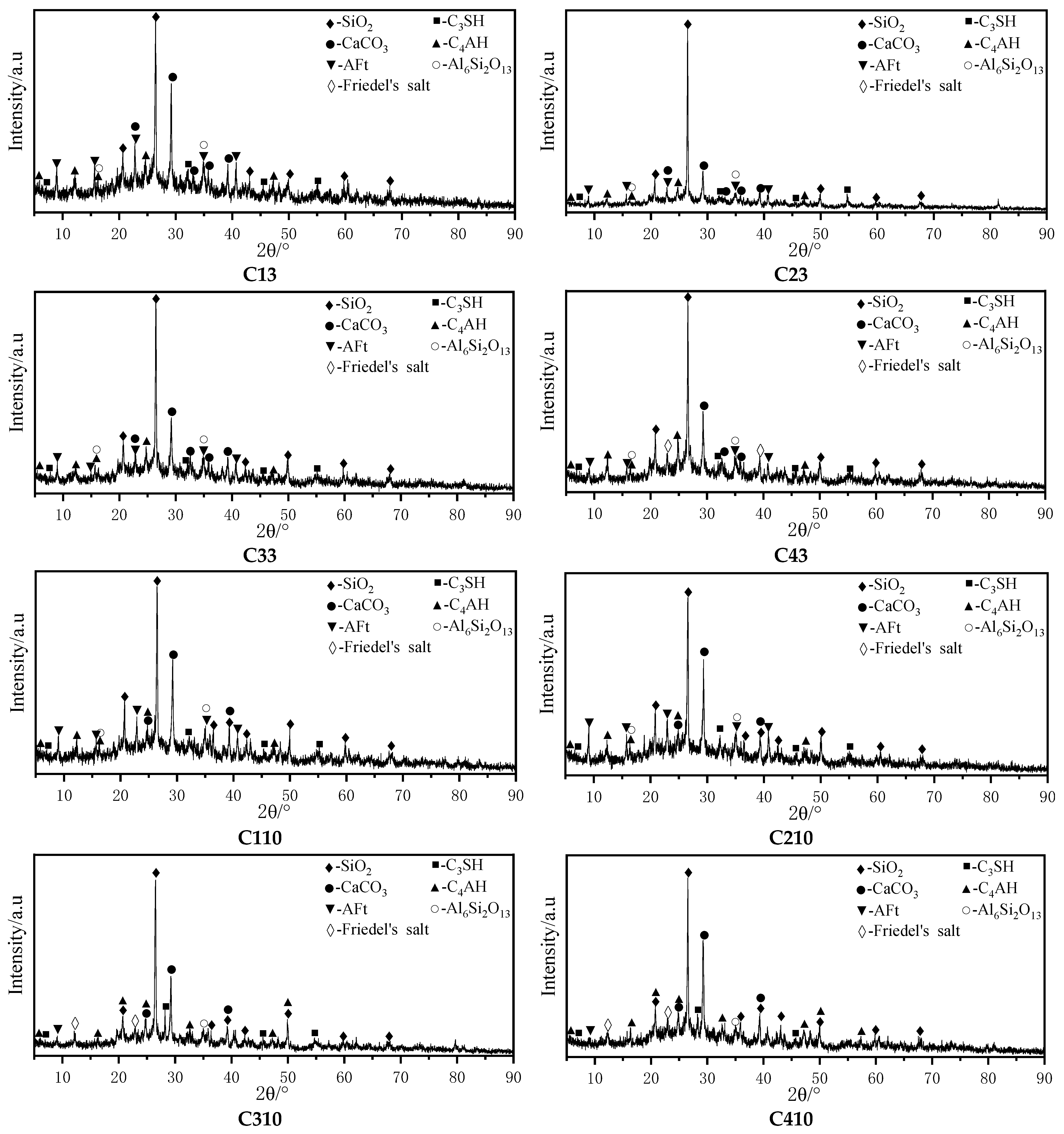
4.2. Crystal Calibration Analysis with XRD Diffraction

Figure 10 shows the calibration of the spectra after the XRD test. The XRD diffraction spectra of the paste backfill specimens were calibrated for SiO2, Al6Si2O13, AFt, C3SH (3CaO·SiO2·yH2O), C4AH (4CaO·Al2O3·H2O), CaCO3, and Friedel’s salt. As the fly ash, gangue, and slag in the specimen contained large amounts of SiO2, the XRD diffraction spectra of the specimens were very prominent in the calibration of SiO2. Al6Si2O13 (mullite) was also present in the fly ash and gangue. The main hydration products of cement, fly ash, and other raw materials included C3SH, C4AH, and other substances. These hydration products were in a gel state; therefore, the coarse and fine aggregates in the specimens were cemented to each other and solidified the internal fractures in the specimens, which was one of the main reasons for the increased strengths of the specimens. AFt is generated by the chemical reaction among flue-gas desulphurisation gypsum, C3A(3CaO·Al2O3), and C4AF in cement. It is an extremely insoluble, highly crystalline mineral that can quickly consolidate enough free water in the cementing material and grow in the form of needles to form a dense and stable structure, significantly increasing the early strength of the specimen. The CaO in the raw material of the normal hydration reaction reacted chemically with other substances in the specimens to produce the gel product. Thus, the amount of Ca(OH)2 was insignificant, and Ca(OH)2 appeared only as an intermediate product. However, Cl as a stimulant activated the fly ash in the specimen material and reacted with it to produce Friedel’s salt under the action of chloride erosion. Ca(OH)2 was produced in large quantities as a by-product of this reaction. The chemical reactions that produced Ca(OH)2 are shown in Figure 9 and Figure 10. However, in the presence of air, Ca(OH)2 quickly reacts with CO2 in the air, forming CaCO3. Therefore, a large amount of CaCO3 was present in the XRD spectra. Friedel’s salt can also be generated after the reaction of Cl with the gel product inside the specimens. When the number of dry–wet cycles reached 15 or 20, the number of AFt diffraction peaks in the XRD spectra of the paste backfill specimens started to decrease, and diffraction peaks of the Friedel’s salt formed by the reaction started to appear.

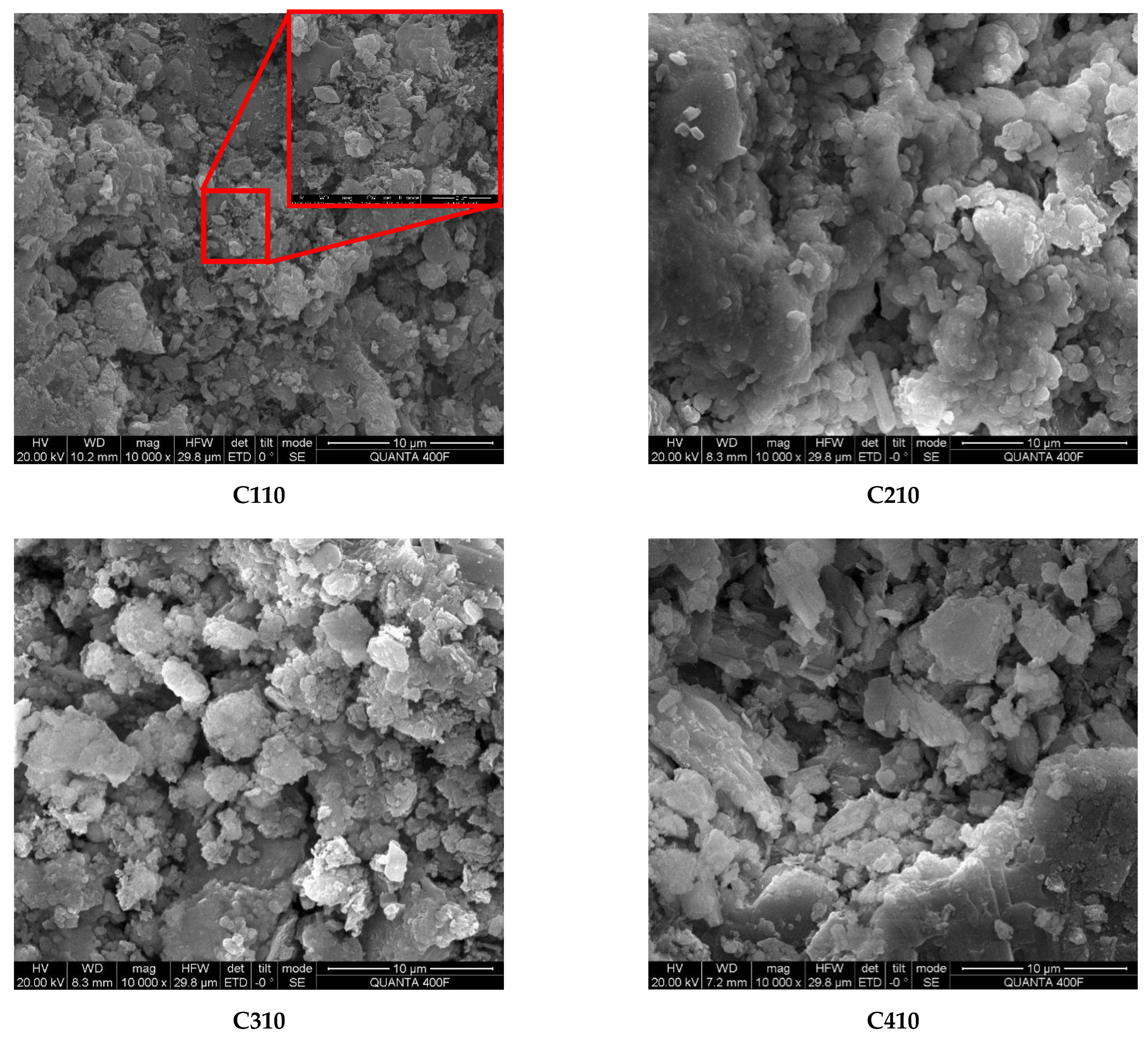
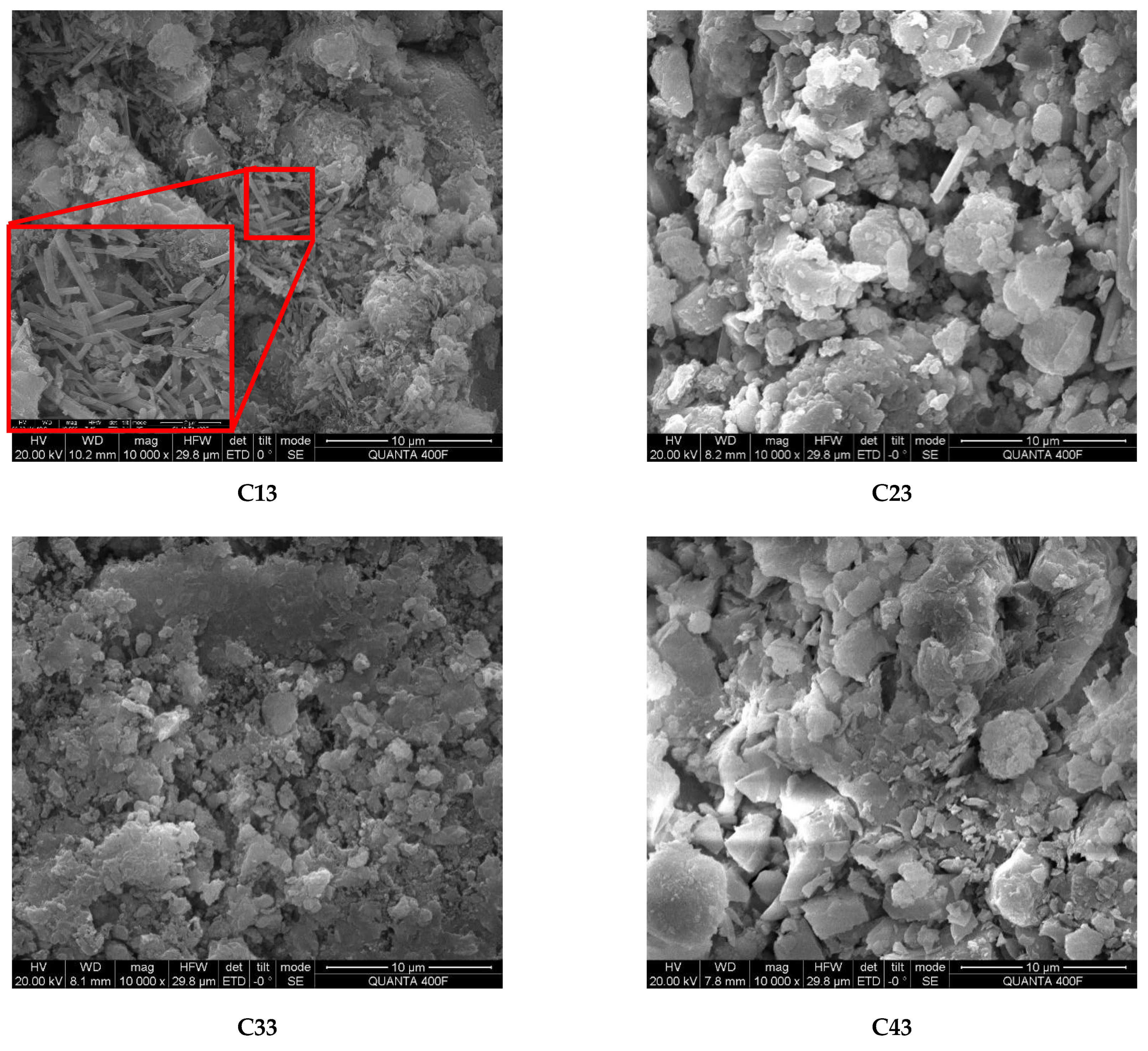
4.3. FE-SEM Mesostructure Analysis

Figure 11 presents the surface morphologies of different test samples under a scanning electron microscope. As shown, the number of pores and fractures in the FE-SEM images of the specimens increased with the number of dry–wet cycles. The internal and surface structures became looser and more broken, respectively. Needle- and rod-like AFt was still observed in the specimens at the fifth and 10th dry–wet cycles. However, as the dry–wet cycles continued, the AFt started to transform into Friedel’s salt in the presence of Cl. This is consistent with the phenomenon observed in the XRD spectrum calibration, where the AFt diffraction peak decreased and that of Friedel’s salt started to appear at the 15th and 20th dry–wet cycles.
As shown in Figure 11, the number of pores and holes in the specimens in a higher-concentration solution was smaller than that for a lower-concentration solution at the same number of dry–wet cycles. Additionally, the surface structures of the specimens in the low-concentration solution were extremely fragmented and had an overall shattered shape, whereas the surfaces of the specimens in the high-concentration solution maintained their integrity relatively well. There was more AFt on the surfaces of the specimens in the higher-concentration solution, because the Cl reacted more completely with AFt to form Friedel’s salt and better maintained the Friedel’s salt so that it could exist stably in the interiors of the specimens.

5. Discussion of Mechanisms

  • Chemical reactions of specimens after mixing
Among the materials of the paste backfill specimens, gangue and slag are incorporated into the filling body system as aggregates. Cement, as a binder, is the main component for ensuring the mechanical strength of the backfill specimens. Because fly ash is potentially active while acting as a fine aggregate, it can undergo a chemical reaction under the stimulus of gypsum to produce a hydraulic substance that enhances the mechanical strength of the paste backfill specimens. Equations (1)–(4) are the hydration reactions of each mineral of cement clinker with water; they occur after the contact of cement particles with water.
2(3CaO·SiO2) + 6H2O → 3CaO·2SiO2·3H2O + 3Ca(OH)2
2(3CaO·SiO2) + 4H2O → 3CaO·2SiO2·3H2O + Ca(OH)2
3CaO·Al2O3 + 6H2O → 3CaO·Al2O3·6H2O
4CaO·Al2O3·Fe2O3 + 7H2O → 3CaO·Al2O3·6H2O + CaO·Fe2O3·H2O
Gypsum is used as an additive to regulate the setting time and mechanical strength of cement. The main hydration products of the cementing system are AFt (ettringite), C–S–H gel, and C–A–H gel. Adding FCD gypsum, which has undergone heat treatment under certain conditions, can improve the physical properties of cement by improving its strength. Fly ash, such as volcanic fly ash and FCD gypsum, can significantly improve the compressive strength of a fly ash “slag” cement-based cementing system and increase the strength of cemented bodies [46]. Equations (5) and (6) are the relevant chemical reactions of fly ash under the action of FCD gypsum as a stimulant. Equation (7) represents the reaction of FCD gypsum in cement with C3A to generate AFt, and Equation (8) represents the reaction of the gel material wrapped on the surface of fly ash particles with AlO2−, Ca2+, and SO42− present in the system to generate AFt.
Ca(OH)2 + Al2O3 → CaO·Al2O3·H2O
Ca(OH)2 + SiO2 + H2O → CaO·SiO2·2H2O
3CaO·Al2O3 + 3CaSO4·2H2O + 26H2O → 3CaO·Al2O3·3CaSO4·32H2O
AlO2− + Ca2+ + OH + SO42− → 3CaO·Al2O3·3CaSO4·32H2O
2.
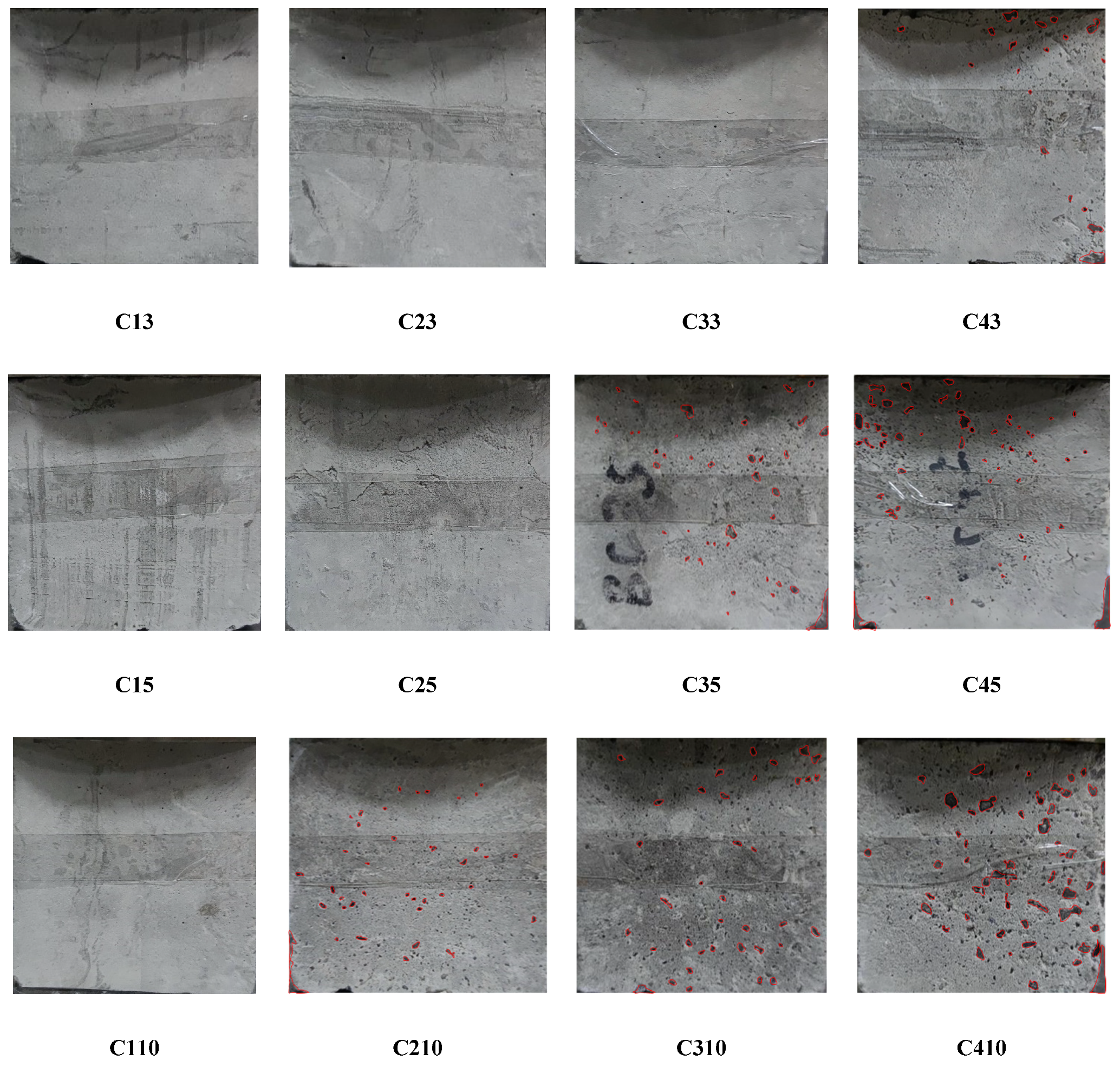
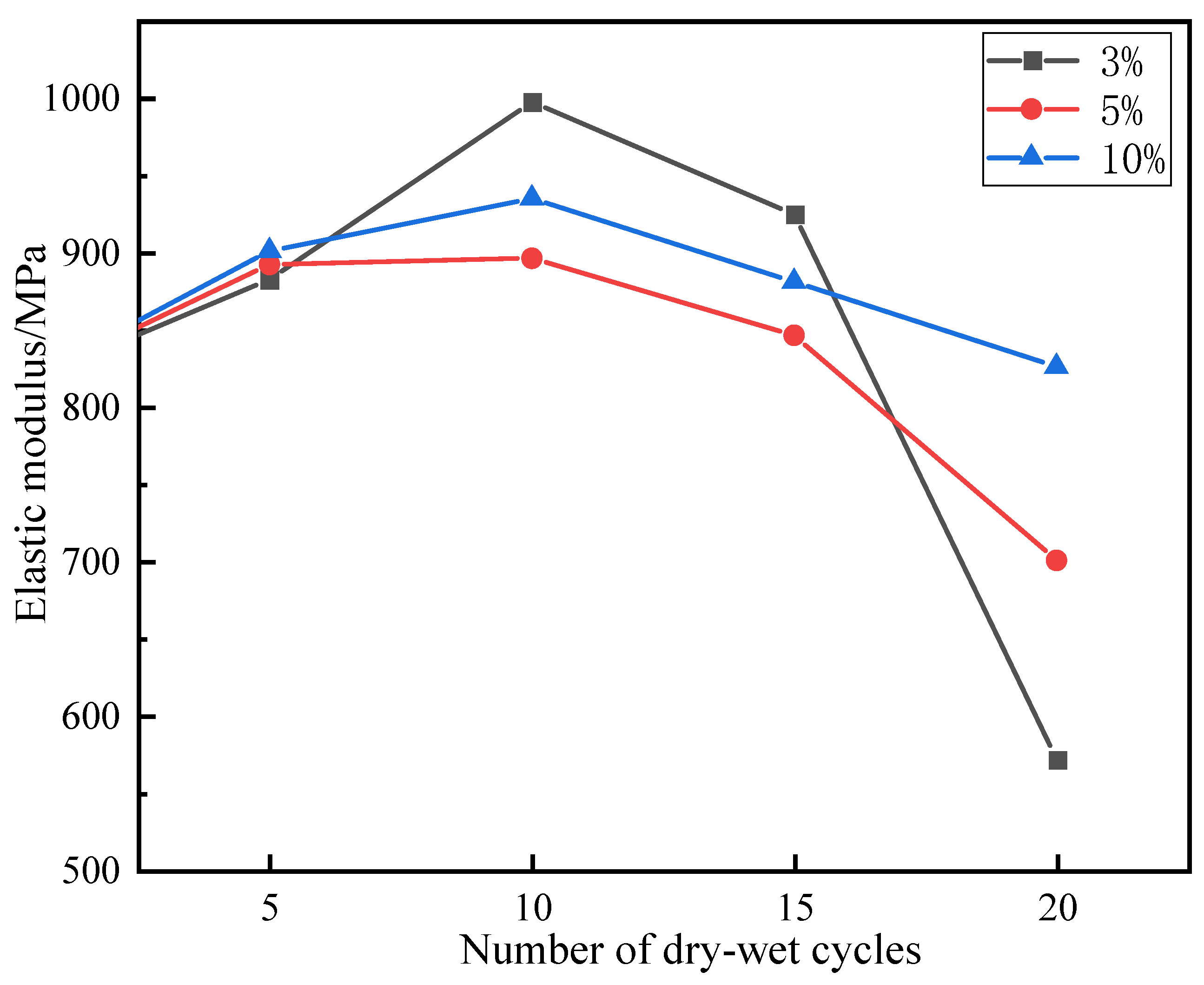
In the fifth and 10th dry–wet cycles, the masses, elastic moduli, and uniaxial strengths of the specimens were increased. Denudation did not obviously occur on the specimen surface. There were more AE signals. At this time, the specimen fractures were mainly vertical. This is because the hydration reaction inside the specimens was not yet complete, and the solution immersion provided additional time for this reaction. Simultaneously, Cl fully reacted with the fly ash inside the specimen through diffusion and chemically activated the SiO2 and Al2O3 in the fly ash, generating new gel products (C–S–H, C–S–H, AFt, etc.) to fill the internal fractures and pores in the specimens. The reaction process is given by Equations (9) and (10). The FTIR and XRD spectra revealed that AFt was not converted to Friedel’s salt in large quantities, and AFt can provide higher strength to the specimens than Friedel’s salt. This led to increases in the masses and uniaxial strengths of the specimens at the beginning of the dry–wet cycles. As indicated by the FE-SEM images, the mesostructures of the specimens became more compact, which enhanced both the mass and the uniaxial strength. Additionally, AE signals were generated by the refracture of the closed original fractures within the specimens under load.
Ca2+ + Al2O3 + 2OH → CaO·Al2O3·H2O
Ca2+ + Al2O3 + Cl + OH → 3CaO·Al2O3·3CaCl2·10H2O
3.
At the 15th and 20th dry–wet cycles, the specimens’ masses, elastic moduli, and uniaxial strengths were reduced. The denudation of the specimen surfaces was more severe, and the interlaced development of macroscopic vertical and horizontal fractures was observed. This is because, as the internal hydration reaction approached completion, the erosion failure of the specimens due to the chloride salt solution and the deterioration of the specimens due to the dry–wet cycles began to appear. First, the chloride salt entered the specimen’s interior through diffusion and reacted chemically with the previously formed gel products to produce Friedel’s salt. These products had certain swelling properties. The expansion and contraction of the gel products during the dry–wet cycles resulted in new fractures inside the specimens. The reaction process is given by Equation (11). Furthermore, the dry–wet cycles physically denudated the surfaces of the specimens through deterioration, and the internal structures of the specimens were also damaged. Under the coupled effects of these two factors and other related factors, the masses and uniaxial strengths of the specimens were reduced. The IR and XRD spectra revealed that Friedel’s salt started to appear in the late stage of the dry–wet cycles. Additionally, the FE-SEM images indicated that with the increase in the number of dry–wet cycles, the surfaces of the specimens started to deteriorate, and numerous pores and fractures appeared inside the specimen. As a result, the overall structure became loose.
3CaO·Al2O3·CaSO4·12H2O + 2Cl → 3CaO·Al2O3·CaCl2·10H2O + SO42− + 2H2O
4.
A higher-concentration solution can enter the specimen interior and enhance the uniaxial strength of the specimen faster owing to the higher concentration gradient. The strength deterioration rates of the specimens in the higher-concentration solution were lower than those for the low-concentration solution, but the surface denudation was significant. When the concentration of chloride salt in the solution is higher, the erosion on the surface of the specimen is more severe, and the chloride salt is more likely to invade the specimen interior and chemically react with the interior components, which has a positive effect on the specimen’s strength. In a large amount, a solution with a high concentration of chloride salt can react with the internal components of the specimens or precipitate during the dry–wet cycles. This partially fills the fractures and pores inside the specimens and has a buffering effect on the strength deterioration of the specimens under the coupled effects of dry–wet cycles and chloride erosion. Moreover, a high concentration of Cl can maintain Friedel’s salt; conversely, a lower concentration of Cl leads to a looser internal structure because it cannot maintain Friedel’s salt, as shown in Equations (12) and (13). These factors led to the considerable strength deterioration of the specimens subjected to dry–wet cycles in the low-concentration solution. The IR and XRD spectra indicated that Friedel’s salt started to appear late in the dry–wet cycles, and the FE-SEM images indicated that the specimens in the high-concentration solution had fewer pores and fractures than those in the low-concentration solution at the same number of dry–wet cycles. The specimens in the high-concentration solution had better integrity than those in the low-concentration solution.
CaCl2 + 3Ca(OH)2 + 12H2O → CaCl2·3Ca(OH)2·12H2O
3CaO·Al2O3·CaCl2·10H2O (s) → 4Ca2+ + 2Al(OH)4 +2Cl + 4OH + 4H2O

6. Conclusions

  • At the early stage of dry–wet cycling in a chloride solution, the strengths of paste specimens were improved owing to the continued hydration reaction and chloride catalysis.
  • With increasing drying and wetting cycles of paste specimens in a chlorine salt solution, the erosion effect of chlorine salts and the deterioration effect of the dry–wet cycles began to appear, and the strengths of the paste specimens began to decline.
  • Compared with the low-concentration chlorine salt solution, the high-concentration solution can improve the strength of the paste faster and have a buffering effect on the strength deterioration of the paste.
  • The changes in the mechanical properties of desulphurised gypsum backfill samples under the coupled effects of chloride salt erosion and dry–wet cycles were investigated, and it was determined that the desulphurised gypsum backfill could maintain a certain strength in this special environment. The results provide a laboratory reference and theoretical basis for the field application of desulphurised gypsum backfill.
  • In this study, backfill samples were taken as the research objects. There are size differences between the samples and field backfill. Therefore, it is necessary to study the mechanical properties of backfill under the coupled effects of chloride erosion and dry–wet cycles at the field scale.

Author Contributions

Conceptualisation, S.W.; methodology, S.W.; software, S.W.; validation, S.W. and T.J.; data curation, D.Y.; writing—original draft preparation, S.W.; writing—review and editing, S.W., F.W., D.Y., T.J., and Z.Z.; funding acquisition, F.W. All authors have read and agreed to the published version of the manuscript.

Funding

This research was funded by the National Natural Science Foundation of China (Nos. 51904162, 51904167, and 52074169), the China Postdoctoral Science Foundation (No. 2020M682208), the SDUST Research Fund (No. 2019TDJH101), the Elite Talent Project of SDUST, and the Open Research Fund for the Key Laboratory of Safety and High-Efficiency Coal Mining (No. JYBSYS2019201).

Data Availability Statement

All data used to support the findings of this study are included within the article, and there are no restrictions on data access.

Conflicts of Interest

The authors declare no conflict of interest.

Abbreviations

FTIRFourier-Transform Infrared Spectroscopy
XRDX-Ray Diffraction Analysis
FE-SEMField-Emission Scanning Electron Microscopy
XRFX-Ray Fluorescence
AftEttringite
C–A–HxCaO·Al2O3·yH2O
AEAcoustic Emission
RAThe Ratio of Rise Time to Amplitude
PDSPressure Density Stage
LESLinear Elastic Deformation Stage
PPYSPre-Peak Yielding Stage
PPDSPost-Peak Damage Stage
C–S–HxCaO·SiO2·yH2O
C3SH3CaO·SiO2·yH2O
C4AH4CaO·Al2O3·H2O
C3A3CaO·Al2O3
C4AF3CaO·Al2O3·Fe2O3

References

  1. Wang, F.; Jiang, B.; Chen, S.; Ren, M. Surface collapse control under thick unconsolidated layers by backfilling strip mining in coal mines. Int. J. Rock Mech. Min. Sci. 2019, 113, 268–277. [Google Scholar] [CrossRef]
  2. Li, L.; Yang, P. A numerical evaluation of continuous backfilling in cemented paste backfilled stope through an application of wick drains. Int. J. Min. Sci. Technol. 2015, 25, 897–904. [Google Scholar] [CrossRef]
  3. Choudhary, B.; Kumar, S. Underground void filling by cemented mill tailings. Int. J. Min. Sci. Technol. 2013, 23, 893–900. [Google Scholar] [CrossRef]
  4. Feng, G.; Jia, X.; Guo, Y.; Qi, T.; Li, D.; Li, Z.; Feng, J.; Liu, G.; Song, K.; Kang, L. Influence of the wasted concrete coarse aggregate on the performance of cemented paste backfill. J. China Coal Soc. 2015, 40, 1320–1325. [Google Scholar]
  5. Chen, S.; Du, Z.; Zhang, Z.; Yin, D.; Feng, F.; Ma, J. Effects of red mud additions on gangue-cemented paste backfill properties. Powder Technol. 2020, 367, 833–840. [Google Scholar] [CrossRef]
  6. Li, F.; Yin, D.; Zhu, C.; Wang, F.; Jiang, N.; Zhang, Z. Effects of Kaolin Addition on Mechanical Properties for Cemented Coal Gangue-Fly Ash Backfill under Uniaxial Loading. Energies 2021, 14, 3693. [Google Scholar] [CrossRef]
  7. Cheng, H.-Y.; Wu, S.-C.; Zhang, X.-Q.; Wu, A.-X. Effect of particle gradation characteristics on yield stress of cemented paste backfill. Int. J. Miner. Met. Mater. 2020, 27, 10–17. [Google Scholar] [CrossRef]
  8. Fall, M.; Pokharel, M. Coupled effects of sulphate and temperature on the strength development of cemented tailings backfills: Portland cement-paste backfill. Cem. Concr. Compos. 2010, 32, 819–828. [Google Scholar] [CrossRef]
  9. Liu, H.; Zhang, J.; Zhou, N.; Sheng, L.; Zhang, L.; Zhu, L.; Wang, L. Study of the leaching and solidification mechanism of heavy metals from gangue-based cemented paste backfilling materials. J. China Univ. Min. Technol. 2021, 50, 523–531. [Google Scholar]
  10. Zhang, J.; Tu, S.; Cao, Y.; Tan, Y.; Xin, H.; Pang, J. Coal gangue intelligent separation and backfilling technology and its engi-neering application in underground coal mine. J. China Univ. Min. Technol. 2021, 50, 523–531. [Google Scholar]
  11. Chen, S.; Jiang, T.; Zhang, H.; Kong, K.; Bie, L. Emission reduction process for dechlorinating flue-gas desulfurization gypsum and reducing wastewater effluents: Application prospects from laboratory-scale studies. Energy Sci. Eng. 2020, 8, 2662–2679. [Google Scholar] [CrossRef]
  12. Chandara, C.; Azizli, K.A.M.; Ahmad, Z.A.; Sakai, E. Use of waste gypsum to replace natural gypsum as set retarders in portland cement. Waste Manag. 2009, 29, 1675–1679. [Google Scholar] [CrossRef]
  13. Hou, K. Flue gas desulfurization slag from power plant replaces natural gypsum as cement retarder. Cement 2005, 10, 21–23. [Google Scholar]
  14. Tzouvalas, G.; Rantis, G.; Tsimas, S. Alternative calcium-sulfate-bearing materials as cement retarders: Part II. FGD gypsum. Cem. Concr. Res. 2004, 34, 2119–2125. [Google Scholar] [CrossRef]
  15. Colak, A. The long-term durability performance of gypsum–Portland cement–natural pozzolan blends. Cem. Concr. Res. 2002, 32, 109–115. [Google Scholar] [CrossRef]
  16. Guo, X.L.; Shi, H.S. Thermal treatment and utilization of flue gas desulphurization gypsum as an admixture in cement and concrete. Constr. Build. Mater. 2008, 22, 1471–1476. [Google Scholar] [CrossRef]
  17. Guo, X.-L.; Shi, H.-S.; Liu, H.-Y. Effects of a combined admixture of slag powder and thermally treated flue gas desulphurization (FGD) gypsum on the compressive strength and durability of concrete. Mater. Struct. 2008, 42, 263–270. [Google Scholar] [CrossRef]
  18. Zhang, Z.; Gao, L.; Yang, L.; Zhang, L.; Zhao, F. Study on water resistant gypsum blocks from desulfurization gypsum. Fly Ash Compr. Utilizat. 2009, 2, 27–30. [Google Scholar]
  19. Qiao, X.; Poon, C.; Cheeseman, C. Use of flue gas desulphurization (FGD) waste and rejected fly ash in waste stabilization systems. Waste Manag. 2006, 26, 141–149. [Google Scholar] [CrossRef]
  20. Li, B.; Yin, H.; Mao, X.; Li, Y.; Zhang, L.; Liu, R.; Qiu, P. Macroscopic and microscopic fracture features of concrete used in coal mine under chlorine salt erosion. Int. J. Min. Sci. Technol. 2016, 26, 455–459. [Google Scholar] [CrossRef]
  21. Zhang, H. Effect of Chloride on Early Mechanical Properties of Cement Paste Filling Body. In Proceedings of the Technical Forum on Wastewater Treatment and Zero Discharge of High-salt Wastewater, Hangzhou, China, 25 October 2019. [Google Scholar]
  22. Zhang, J.; Yao, Y.; Wang, X.; Guo, S.; Dong, G. Study on the combination of Ettringite and chloride ion in different chloride solutions. J. Build. Mater. 2021, 6, 1–9. [Google Scholar]
  23. Ekolu, S.; Thomas, M.; Hooton, R.D. Pessimum effect of externally applied chlorides on expansion due to delayed ettringite formation: Proposed mechanism. Cem. Concr. Res. 2006, 36, 688–696. [Google Scholar] [CrossRef]
  24. Du, Z.; Chen, S.; Yin, D.; Yao, D.; Zhang, Z. Experimental study of stability of paste backfill under chloride erosion environment. J. China Univ. Min. Technol. 2021, 50, 532–538, 547. [Google Scholar]
  25. Zhu, Q.; Jiang, L.; Chen, Y.; Xu, J.; Mo, L. Effect of chloride salt type on chloride binding behavior of concrete. Constr. Build. Mater. 2012, 37, 512–517. [Google Scholar] [CrossRef]
  26. Farnam, Y.; Washington, T.; Weiss, W. The Influence of Calcium Chloride Salt Solution on the Transport Properties, of Cementitious Materials. Adv. Civ. Eng. 2015, 2015, 1–13. [Google Scholar] [CrossRef]
  27. Chen, S.; Du, Z.; Zhang, Z.; Zhang, H.; Xia, Z.; Feng, F. Effects of chloride on the early mechanical properties and microstructure of gangue-cemented paste backfill. Constr. Build. Mater. 2020, 235, 117504. [Google Scholar] [CrossRef]
  28. Wang, X.; Shi, C.; He, F.; Yuan, Q.; Wang, D.; Huang, Y.; Li, Q. Chloride binding and its effects on microstructure of cement-based materials. J. Chin. Ceram. Society 2013, 41, 187–198. [Google Scholar]
  29. Chen, S.; Jiang, T.; Wang, H.; Feng, F.; Yin, D.; Li, X. Influence of cyclic wetting-drying on the mechanical strength characteristics of coal samples: A laboratory-scale study. Energy Sci. Eng. 2019, 7, 3020–3037. [Google Scholar] [CrossRef]
  30. Li, Y.; Ba, M.; Liu, J.; He, Z. Resistance to chloride erosion of cement matrix composite materials under dry-wet cycling and their micro-structural changes. Acta Mater. Comp. Sin. 2017, 34, 2856–2865. [Google Scholar]
  31. Chen, Y.; Gao, J.; Tang, L.; Li, X. Resistance of concrete against combined attack of chloride and sulfate under drying–wetting cycles. Constr. Build. Mater. 2016, 106, 650–658. [Google Scholar] [CrossRef]
  32. Aldaood, A.; Bouasker, M.; Al-Mukhtar, M. Impact of wetting–drying cycles on the microstructure and mechanical properties of lime-stabilized gypseous soils. Eng. Geol. 2014, 174, 11–21. [Google Scholar] [CrossRef]
  33. Kalkan, E. Impact of wetting–drying cycles on swelling behavior of clayey soils modified by silica fume. Appl. Clay Sci. 2011, 52, 345–352. [Google Scholar] [CrossRef]
  34. Zhou, S.; Lv, H.; Wu, Y. Degradation behavior of concrete under corrosive coal mine environment. Int. J. Min. Sci. Technol. 2019, 29, 307–312. [Google Scholar] [CrossRef]
  35. Zhang, X.; Chen, R.; Jian, W. Study on water conversion law and solidification mechanism of cement-slag-fly ash solidified silt. J. Eng. Geol. 2021, 6, 1–11. [Google Scholar]
  36. Jiang, T. Experimental Study on the Effect of Flue Gas Desulfurization Gypsum Dechlorinating on the Properties of Paste Back-Filling Materials. Master’s Thesis, Shandong University of Science and Technology, Qingdao, China, 2021. [Google Scholar]
  37. Ma, J.; Jiang, N.; Wang, X.; Jia, X.; Yao, D. Numerical Study of the Strength and Characteristics of Sandstone Samples with Combined Double Hole and Double Fissure Defects. Sustainability 2021, 13, 7090. [Google Scholar] [CrossRef]
  38. Wang, Z. Effect of dry-wet cycles on mechanical properties of fly ash high-moisture materials. Fly Ash Compr. Utilizat. 2018, 3, 40–42. [Google Scholar]
  39. Ammasi, A.K. Ragul Strength and Durability of High Volume Fly Ash in Engineered Cementitious Composites. Mater. Today Proc. 2018, 5, 24050–24058. [Google Scholar] [CrossRef]
  40. Li, Z.; Ma, J. Preparation of Ca-Al hydrotalcite-like compounds and their desilication in sodium aluminate solution. Sci. Sin. Chim. 2010, 40, 577–584. [Google Scholar] [CrossRef]
  41. Sun, R.; Hu, X.; Ling, Y.; Zuo, Z.; Zhuang, P.; Wang, F. Chloride diffusion behavior of engineered cementitious composite under dry-wet cycles. Constr. Build. Mater. 2020, 260, 119943. [Google Scholar] [CrossRef]
  42. Hirao, H.; Yamada, K.; Takahashi, H.; Zibara, H. Chloride Binding of Cement Estimated by Binding Isotherms of Hydrates. J. Adv. Concr. Technol. 2005, 3, 77–84. [Google Scholar] [CrossRef] [Green Version]
  43. Suryavanshi, A.; Narayan, S. Stability of Friedel’s salt in carbonated concrete structural elements. Cem. Concr. Res. 1996, 26, 729–741. [Google Scholar] [CrossRef]
  44. Wang, X.; Wang, E.; Liu, X.; Jia, H.; Li, D.; Wang, H. Time-frequency-space response of damage evolution for concrete based on AE-UT joint monitoring under step-loading. Int. J. Min. Sci. Technol. 2019, 48, 268–277. [Google Scholar]
  45. Shiotani, T.; Ohtsu, M.; Ikeda, K. Detection and evaluation of AE waves due to rock deformation. Constr. Build. Mater. 2001, 15, 235–246. [Google Scholar] [CrossRef]
  46. Lu, Q.; Wang, X.; Fu, S.; Li, Y. Effect of desulphurization gypsum on the strength and microstructure of the sludge ash ce-mentitious system. J. Zhengzhou Univ. (Eng. Sci.) 2021, 6, 1–6. [Google Scholar]
Figure 1. Photographs of raw materials.
Minerals 11 00882 g001
Figure 2. Mechanical performance test flow.
Minerals 11 00882 g002
Figure 3. Deterioration of the surfaces of paste backfill with desulphurised gypsum under different conditions.
Minerals 11 00882 g003
Figure 4. Variations of the backfill mass with respect to the number of dry–wet cycles at different solution concentrations.
Minerals 11 00882 g004
Figure 5. Variations in the peak stresses of backfill specimens under uniaxial compression.
Minerals 11 00882 g005
Figure 6. Variations in the elastic moduli of backfill specimens.
Minerals 11 00882 g006
Figure 7. AE monitoring during uniaxial compression.
Minerals 11 00882 g007aMinerals 11 00882 g007b
Figure 8. Mesoscopic test equipment.
Minerals 11 00882 g008
Figure 9. FTIR spectra of filled specimens.
Minerals 11 00882 g009
Figure 10. Sample XRD spectra.
Minerals 11 00882 g010
Figure 11. FE-SEM images of the filled specimens.
Minerals 11 00882 g011aMinerals 11 00882 g011b
Table 1. Raw material chemical compositions for the backfill sample.
Raw MaterialsChemical Composition and Content (%)
SiO2Al2O3CaOMgOSO3Fe2O3
Cement22.304.8262.472.341.823.83
Fly ash56.3018.0511.843.011.194.93
Coal gangue59.8320.104.891.22-6.52
Blast furnace slag35.8312.7338.097.86-2.79
Desulphurised gypsum24.402.6232.251.3337.580.73
Table 2. Uniaxial strengths of desulphurisation gypsum-filled specimens.
Solution ConcentrationUniaxial Compressive Strength (MPa)
Number
of
Dry–Wet Cycles
3%Average5%Average10%Average
010.7710.7410.1410.49--------
59.4110.9712.0210.8010.4710.6110.8610.6410.2012.1912.9011.76
1012.7211.8110.6511.7310.8111.739.9710.8410.9613.1510.2611.46
1511.2011.049.5910.619.7510.378.659.5910.1311.3112.6111.35
208.957.949.948.947.909.5910.259.259.1411.9812.0811.07
Table 3. Elastic moduli of backfill specimens with desulphurised gypsum.
Solution ConcentrationElastic Modulus (MPa)
Number
of
Dry–Wet Cycles
3%Average5%Average10%Average
0835.21764.58833.17810.99--------
5725.601019.87902.74882.74945.18819.49912.33892.33756.211025.90921.05901.05
101044.36931.051017.71997.71755.93916.95866.44846.44819.871030.47955.17935.17
15942.89886.97944.93924.93884.44888.26916.35896.35627.941004.25846.10826.10
20603.23520.11591.67571.67647.76733.23720.49700.49646.371096.05901.21881.21
Publisher’s Note: MDPI stays neutral with regard to jurisdictional claims in published maps and institutional affiliations.

