Article

Surrounding Rock Stability Control Technology of Roadway in Large Inclination Seam with Weak Structural Plane in Roof

1
State Key Laboratory for Geomechanics and Deep Underground Engineering, China University of Mining and Technology, Xuzhou 221116, China
2
State Key Laboratory of Coal Resources and Safe Mining, China University of Mining and Technology, Xuzhou 221116, China
3
School of Mechanics and Civil Engineering, China University of Mining and Technology, Xuzhou 221116, China
*
Author to whom correspondence should be addressed.
Minerals 2021, 11(8), 881; https://doi.org/10.3390/min11080881
Submission received: 6 June 2021 / Revised: 19 July 2021 / Accepted: 13 August 2021 / Published: 15 August 2021

Abstract

:
The surrounding rock control technology of mining roadways in large inclination seams with a weak structural plane in the roof is one of the most challenging fields in underground roadway support. In view of the serious deformation of the surrounding rock of the transportation roadway in the 1201 working face of a mine, the deformation and failure characteristics and instability mechanism of the surrounding rock of the roadway are analysed. The self-stability mechanical model of the roof block structure of the roadway with a large inclination under the support effect is established, and the support concept of “high pre-stressed asymmetric” and the combined support method of bolts, wire mesh, and cables are proposed. The rationality of the supporting scheme is verified by numerical simulation. The results show that: compared with bolt and wire mesh support, the maximum shear displacement of the roof’s weak layer under the combined support of bolt, wire meshes, and cable before and after mining is reduced by 86.78% and 83%, respectively, and the maximum total displacement of surrounding rock surface is reduced by 49.22% and 37.1%, respectively. The field monitoring results show that the combined support scheme can effectively control the deformation of the surrounding rock.

1. Introduction

It is generally believed that a coal seam with inclination angle between 35–55° can be called the coal seam with large inclination [1]. The stability of mining roadways in a steeply dipping coal seam is an important precondition to ensure the safe and efficient mining of this kind of coal seam. Compared with a roadway in the nearly horizontal and gently inclined coal seam [2,3,4], this kind of roadway is obviously affected by mining dynamic pressure and asymmetric load, the stress distribution of surrounding rock is very complex, and the deformation difference of roof, floor, and two sides is very significant, often showing obvious asymmetric distribution characteristics [5,6]. Especially when the roof contains weak structural plane, the asymmetric deformation of roadway is more prominent [7]. If we do not fully understand the fracture evolution law and instability mechanism of surrounding rock of this kind of roadway, blindly designing support parameters and support forms, it is very easy to cause instability and damage of this kind of roadway, which will bring great hidden danger to coal mine production and personnel safety, and cause immeasurable economic losses to the country. Therefore, it is of great significance to study the stability control system and technology of surrounding rock of roadway in the large inclination seam with a weak structural plane in the roof to ensure the safe and efficient production of the mine.
There are four main deformation and failure characteristics in the mining roadway of steeply dipping coal seam: first, the distribution of deformation and plastic zone of roadway are obviously asymmetric [8,9]. Second, a prominent floor heave in roadway [10,11]. Third, the problem of roadway spalling is obvious [12,13]. Finally, large span roadway with the thin roof is prone to shear sliding failure along the weak structural plane of strata, which leads to shear failure of support system [14]. One reason is the non-uniformity of load distribution, another is the non-coordination between the support system and surrounding rock deformation. It is an important engineering problem to choose which control technology to solve the surrounding rock deformation of roadway in the steep seam.
With the continuous development of China’s roadway support technology, its support mode gradually changes from the traditional passive support forms such as woodpile support, concrete masonry support, and steel frame support to the active support forms such as bolt shortcoming support, bolt mesh cable shortcoming support and bolt grouting support, and the properties of support materials also change from low strength and low elongation to high strength and high elongation [15,16,17,18,19]. Generally speaking, roadway support form and strength design are closely related to the surrounding rock mining conditions and instability mode. Due to the influence of the dip angle effect, the surrounding rock structure of steeply dipping coal seam roadway often shows asymmetric and unbalanced instability characteristics, so its control is difficult. At present, scholars from the mining method [20], roadway section shape [21], and support form [22] have carried out studies on the surrounding rock control technology of roadway in steeply dipping coal seam, and the surrounding rock control theory and system of roadway in steeply dipping coal seam roadway have gradually formed, such as asymmetric support [23], reinforcement and support of key parts [24,25], coupling support [26], advanced grouting modified rock support [27,28], and good engineering application results are obtained. However, due to the complexity of geological conditions, the support means and methods have strong geological dependence and do not have universal practical value. The supporting scheme design is highly consistent with its instability mode. The mechanism of surrounding rock instability mode of roadway in large inclination seam considering the sliding effect of roof weak structural plane is quite different from that without considering weak structural plane, so the supporting design is not the same.
In this paper, firstly, the deformation and failure characteristics of roadway surrounding rock under the conditions of no weak structural plane and with the weak structural plane are compared and analysed. Then, based on the instability characteristics of roof surrounding rock, the mechanical model of roof stability under bolt (cable) combined support is established, the mechanical criterion of roof stability under support is deduced, and the mechanical basis of “high pre-stress asymmetric” support concept is discussed. Finally, based on the support concept, the specific support parameters and forms of the 1201 transportation roadway are designed, and the influence of different support forms on the shear slip state and surrounding rock response of coal-clay weak structural plane undermining is compared, which verifies the reliability of the design scheme.

2. Deformation and Failure Characteristics and Instability Mechanism of Surrounding Rock of Roadway in Steep Seam
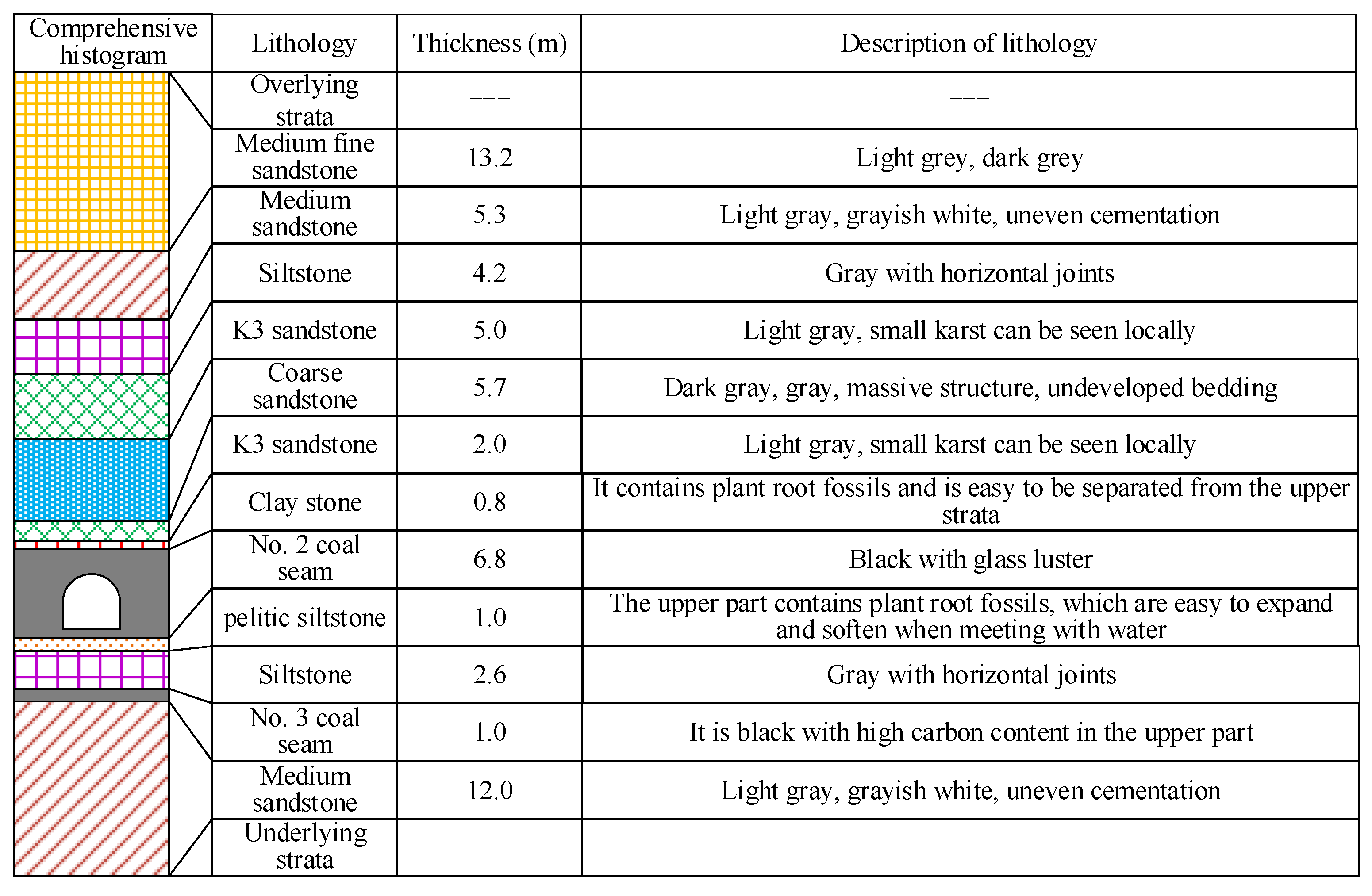
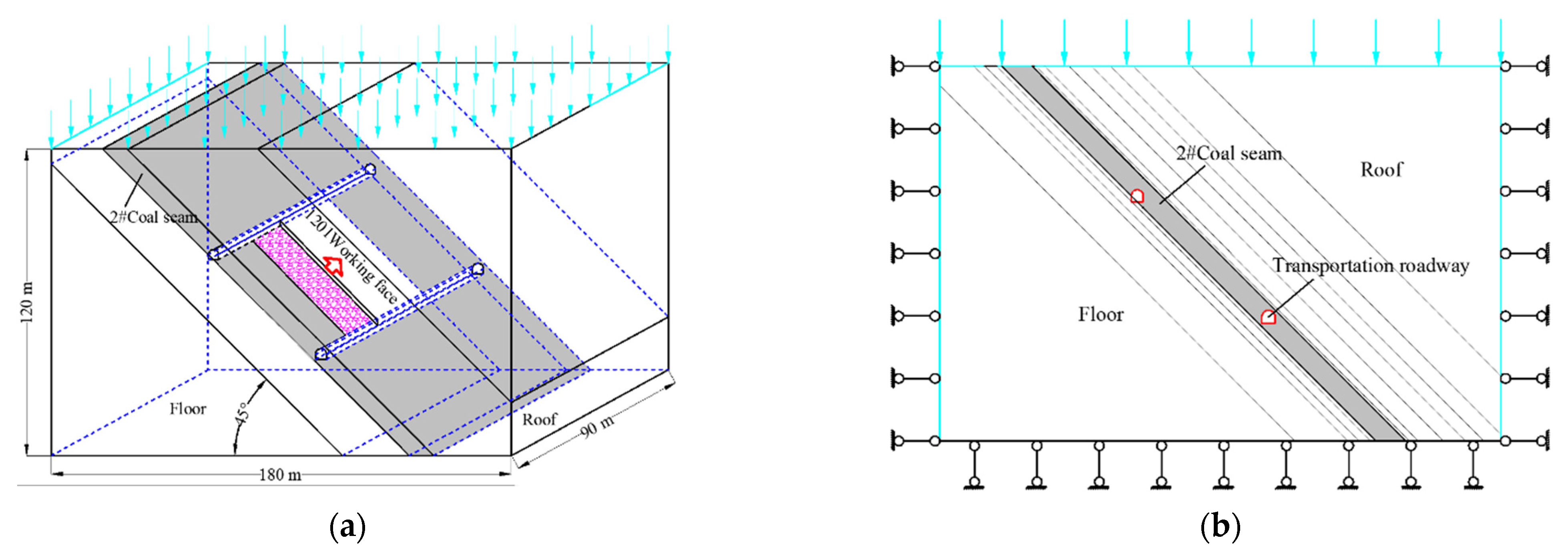
2.1. Background

The 1201 working face of a mine is located in the No. 2 coal seam, and the average thickness of the coal seam is 6.8 m. The average dip angle is 45°, the average burial depth is 400 m. The direct roof consists of clay stone, K3 sandstone (thickness 2 m) and coarse sandstone, and the main roof is mainly K3 sandstone (thickness 5 m), among them, clay rock is the stratum with soft lithology. The direct roof is clay stone with soft lithology, and the coal seam floor is pelitic siltstone with low strength and easy to soften with water. Generally speaking, the rock property of coal seam and roof and floor of 1201 working face is weak, which belongs to typical three soft thick coal seam with large inclination. There is a weak structural plane between the coal seam and the clay stone, which easily leads to the failure of roof separation and sliding. The 1201 transport roadway is located in the coal seam of the working face, the roadway section is a straight-wall semicircular arch, and the roadway width is 4.3 m; the wall height is 2 m. The field monitoring results show that there are many problems in the roadway, such as roof fall, spalling and floor heave, which cannot ensure the normal mining of the working face. The comprehensive histogram of No. 2 coal seam is shown in Figure 1.

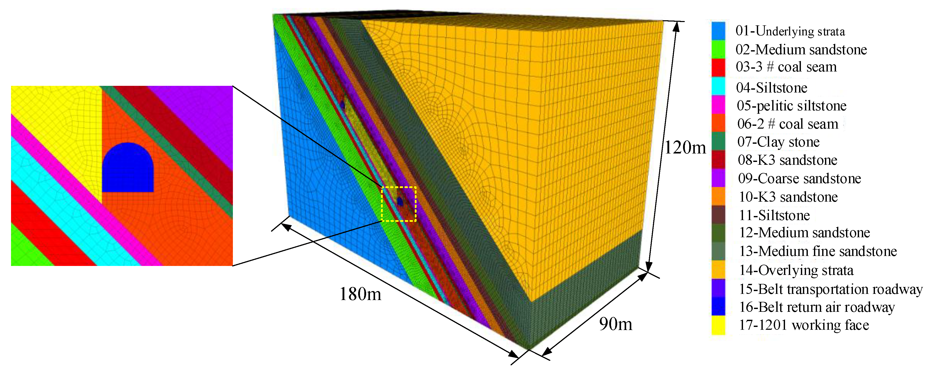
2.2. Establish the Numerical Calculation Model

In order to analyse the deformation and failure characteristics of surrounding rock of mining roadway in the steeply inclination coal seam, taking the transportation roadway of 1201 working face as the engineering background combined with the comprehensive histogram of No. 2 coal seam (Figure 1), a numerical calculation model is established. The diagram is shown in Figure 2, the model length, width, and height are 180 m × 90 m × 120 m, respectively, among which, the length of the working face is 55 m, the dip angle of the coal seam is 45°, and the total height of one mining. There are fixed displacement constraints around and at the bottom of the model, and stress boundary conditions at the top. As the average buried depth of the roadway is about 400 m, the vertical pressure applied on the upper boundary of the model should be 10.0 MPa according to the average unit weight of 25 kN/m3. According to the on-site stress test results, the lateral pressure coefficient is 1.5, the strength of coal seam and rock strata are set to meet Mohr–Coulomb criterion. The transportation roadway is located in the coal seam and is driven along the middle of the coal seam. In order to eliminate the boundary effect, there are 55 m and 60 m wide coal pillars on the left and right sides of the working face, respectively. In addition, in order to improve the calculation accuracy, the coal seam, direct roof, and direct bottom grids are identified. The numerical model is shown in Figure 3.
Table 1 shows the physical and mechanical parameters of each stratum in this simulation. In order to simulate the mining process, the model adopts the step-by-step excavation mode, the excavation is from y = 15 m, the excavation step is 10 m, a total of 6 times of excavation, so the total advance of the working face is 60 m. It should be noted that this section mainly analyses the deformation and failure characteristics of surrounding rock during roadway excavation. In order to simulate the influence of sliding effect of the weak structural plane of the roof on instability mechanism of roadway with large inclination, the interface between roof coal and clay stone of transportation roadway in 1201 working face is set as contact unit for research. The shear stiffness and normal stiffness of the weak structural plane are 2.0 GPa, and the friction angle and cohesion are 15° and 0.1 MPa, respectively, which is compared with that of the roof without weak structural plane.

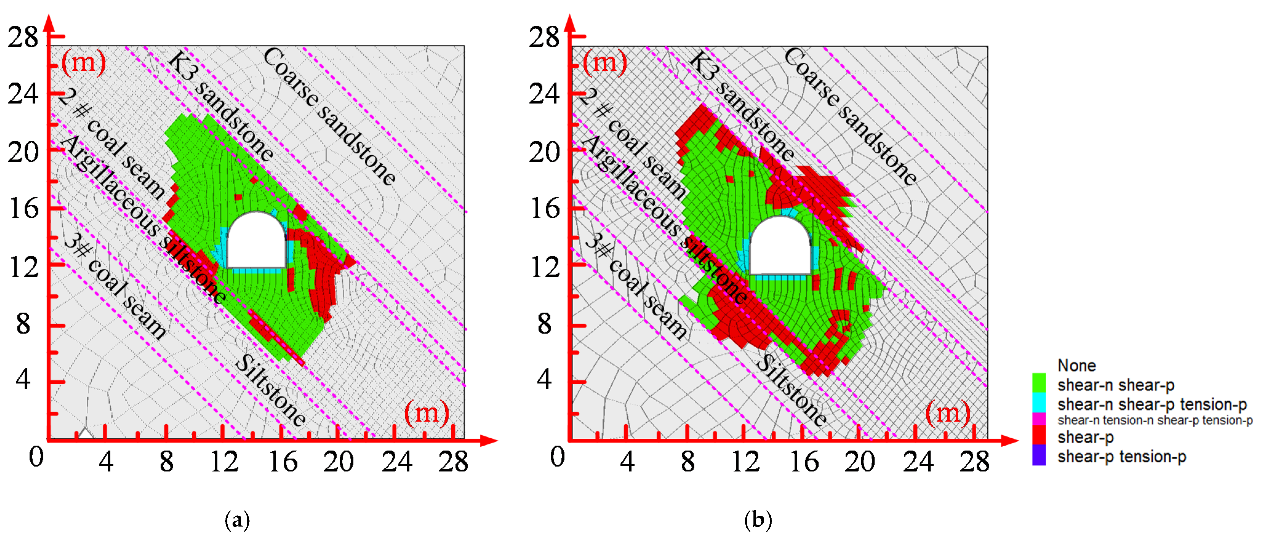
2.3. Analysis of Simulation Results

Figure 4, Figure 5 and Figure 6 shows the total displacement nephogram of surrounding rock, convergence deformation nephogram of the roadway surface, and plastic zone nephogram of roadway roof without a weak structural plane and with weak structural plane, respectively. Figure 7 shows the shear displacement nephogram of the weak structural plane. It can be seen from Figure 4 to Figure 7:
When there is no weak structural plane in the roof, the whole roadway presents obvious asymmetric and introverted deformation characteristics, which shows the displacement of floor is larger than that of roof and the left side displacement is larger than that of right side. The deformation of the roof is larger in the left spandrel than in the right spandrel, the maximum displacement between the left spandrel is 398 mm. The maximum displacement of the floor, left side, and the right side are 403 mm, 398 mm, and 306 mm, respectively. The reasons for the deformation of roadway are as follows: after the excavation of roadway in the steeply dipping coal seam, the surrounding rock moves to the free face in the roadway, but the left side and left spandrels of the roadway are located at the mining site, and the force required to move to the roadway is composed of two parts: the far-field on-site stress and the force decomposed by the self-weight of the coal seam along with its tendency. The right side of the roadway and the right spandrels are located on the non-mining side, and the force needed to move into the roadway is composed of the difference between the far-field stress and the force decomposed by the dead weight of the coal seam along with its tendency. Therefore, the force on the left side of the roadway centre is larger, which leads to larger deformation of the left side of the roadway and the left spandrels.
When the roof contains a weak structural plane, the deformation of surrounding rock presents obvious asymmetric distribution characteristics, the displacement of roof is the largest. The deformation of the left side of the roadway always shows a trend that the top side is larger than the bottom side. The maximum displacement of the left side reaches 505 mm. The deformation of roof shows that the right spandrels are larger than the left spandrels, and the maximum displacement between the right spandrel is 586 mm. The maximum displacement of floor and the right side is 439 mm and 403 mm, respectively. Compared with no weak structural plane, the deformation of the roadway surrounding rock increases significantly. Considering the influence of weak structural plane, the reason why the right spandrels is larger than the left spandrels in roadway deformation is explained as follows: after the excavation of large inclined seam roadway, the surrounding rock moves to the free face in the roadway, but the weak structural plane slides along the rock layer under the shear-force of coal–clay stone’s two weak layers, which leads to the separation of the weak structural plane. Because the right spandrels are close to the weak structural plane, the stress concentration degree is large, which aggravates the deformation of the right spandrels.
The plastic zone of the roadway surrounding rock also presents obvious asymmetric distribution characteristics. When there is no weak structural plane in the roof, the plastic zone of the roadway roof runs through to the clay stone, and the plastic zone of the floor runs through to the pelitic siltstone. The plastic zone in the upper left corner and the lower right corner of the roadway has a larger range, and the failure depth is 8.8 m and 7.4 m. When the roof contains a weak structural plane, the plastic zone of the roadway roof runs through to K3 sandstone, the plastic zone of the floor runs through to siltstone, and the depths of the plastic zone in the upper left corner and the lower right corner of the roadway are 10.0 m and 8.2 m. Compared with no weak structural plane, the range of plastic zone of roadway increases obviously, which is mainly because the additional shear stress caused by the slip effect of the weak structural plane can aggravate the stress concentration degree of the roadway and accelerate the gradual transfer of plastic zone to the depth of roadway.
The maximum shear displacement of the weak structural plane is located to the right of the roadway central axis, and the maximum displacement reaches 405 mm.

2.4. Analysis on Failure Characteristics of Roadway in Steep Coal Seam

According to the results of numerical simulation, the failure characteristics of a large inclined seam roadway with a weak structural plane in the roof can be summarized as follows:
The distribution of deformation and plastic zone of roadway is obviously non-equilibrium. Due to the influence of the additional shear stress caused by the inclination of the overlying strata, the serious areas of roadway deformation and fracture are mostly concentrated in the roadway roof, which is a very high-risk area of roadway roof fall.
The floor heave is serious. Under the influence of the unsymmetrical extrusion load, the bottom bulge of the flow is obvious.
The problem of roadway rib spalling is obvious. The deformation of the two sides presents obvious asymmetry, and the failure degree of the upper side is much higher than that of the lower side along the coal seam dip direction, and the instability mode is mainly shear failure.
The weak structural plane of the roof is prone to shear slip.

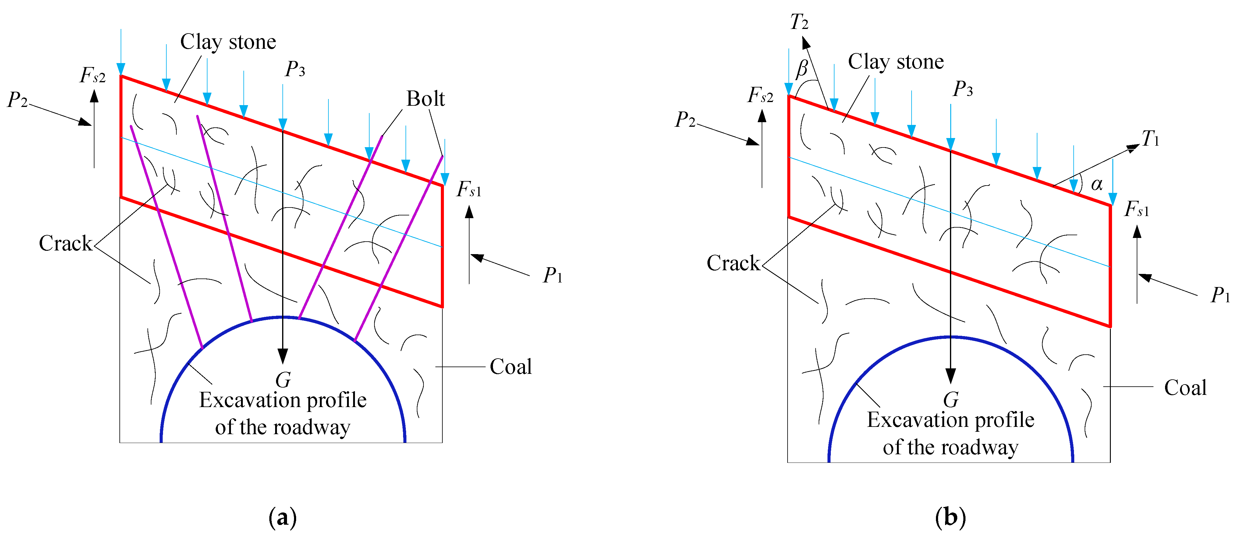
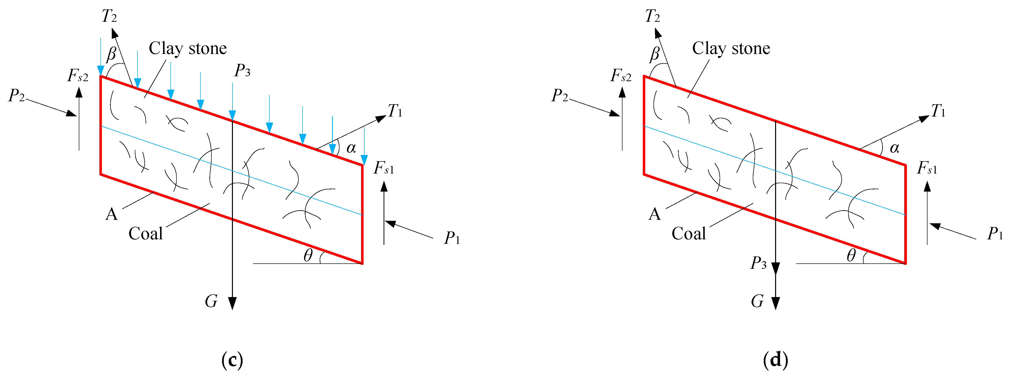
3. Mechanical Mechanism of Stability of Roadway Roof with Large Inclination under Support Failure

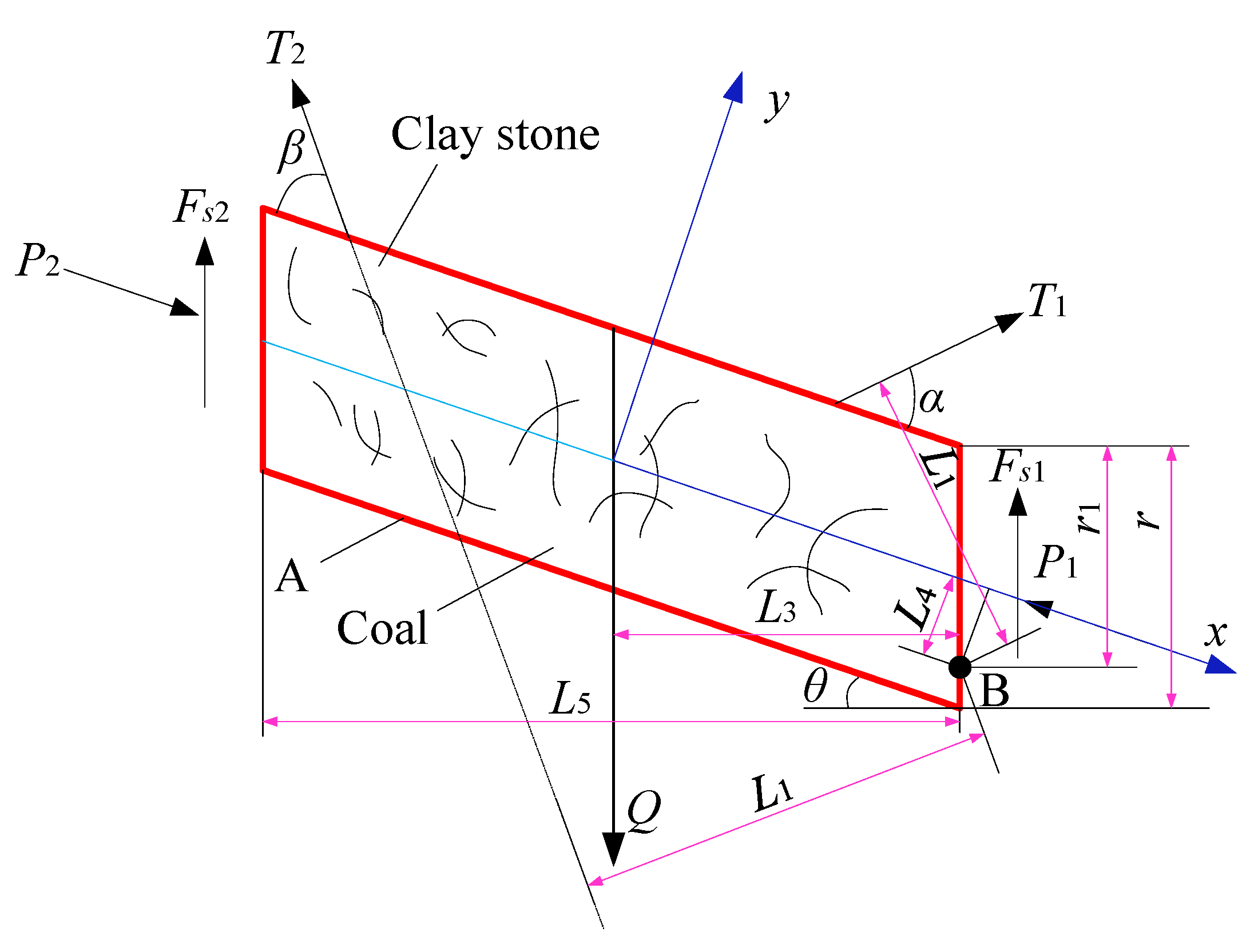
3.1. Establishment of Mechanical Model

Due to the existence of a weak clay stone layer in the roof of the 1201 working face, the plastic zone is easy to gradually expand along with the weak layer to the rock layer, and form a rectangular block-like loose structure in the roof. To ensure the stability of the structure and reduce its shear slip deformation is an important precondition to ensure the safe mining of steeply dipping coal seam roadway.
Figure 8 shows the mechanical model and simplified process of the roof structure of the roadway with a large inclination under the effect of support. The structure is mainly composed of the coal seam above the roadway and clay stone. Figure 8a shows the supporting diagram after the roadway excavation. P1 and P2 in the Figure are the lateral forces parallel to the inclination of the rock. The contact force between the block structure and the overlying strata is P3, and the block weight is G. The shear force on both sides of the square block is Fs1 and Fs2. The support force of bolt in Figure 8a can be equivalent to the form in Figure 8b, in which the support strength of two spandrels of roadway can be equivalent to T1 and T2, respectively, α and β are the dip angles between T1 and T2 with the block structure of roof. In order to simplify the roadway roof coal seam into the square block for analysis, Figure 8b can be transformed into Figure 8c, and P3 can be further simplified as resultant force P3 downward along the block structure centre of roof. The stable mechanical model of the roadway roof structure with a large inclination under final support is shown in Figure 8d.
According to the above mechanical model, the following conditions must be met if the roof structure of the roadway is to be stable for a long time: (1) the block structure of roof meets the force equilibrium conditions along with the coal seam dip (x-axis) and vertical to the coal seam dip (Y-axis). (2) Because the left boundary of the block structure is located at the side of the mining face, it is easier to be destroyed under the influence of mining, which makes the top block structure rotate along any point B of the right boundary. Therefore, the structure should also meet the moment balance condition, where r and r1 are the height of the boundary on both sides of the block structure and the distance from point B of the rotation centre to the upper end of the boundary. Figure 9 shows the moment balance diagram of the roof block structure.
As shown in Figure 9, the block structure of roof needs to meet the stress balance conditions in x-axis and y-axis, so the stress balance Equation is established as follows:
T 1 sin α + T 2 sin β + ( F s 1 + F s 2 ) cos θ Q cos θ = 0
T 1 cos α T 2 cos β ( F s 1 + F s 2 ) sin θ + Q sin θ + P 2 P 1 = 0
Simultaneous Equations (1) and (2) are available:
F s 1 + F s 2 = Q cos θ T 1 sin α T 2 sin β 2 cos θ P 1 P 2 T 1 cos α + T 2 cos β Q sin θ 2 sin θ
To simplify the calculation, let Fs1 = Fs2, then:
F s 2 = Q cos θ T 1 sin α T 2 sin β 4 cos θ P 1 P 2 T 1 cos α + T 2 cos β Q sin θ 4 sin θ
where, α, β meet 0° < α, β ≤ 90° conditions; Q is the resultant force of P3 and G, Q = P3 + G; G = l 2 ( k 1 ) r ρ g cos θ ; l2 is the distance between bolt rows; k is the number of roof bolts; ρ is the average density of rock mass; and g is the acceleration of gravity, 9.8 m/s2.
In addition to Equations (1) and (2), the block structure of roof should also meet the condition of moment balance. Point B is taken as the centre of rotation to establish the moment balance equation as follows:
T 1 L 1 + T 2 L 2 Q L 3 P 1 L 4 + P 2 L 4 + F s 2 L 5 = 0
where L1, L2, L3, L4, and L5 are the vertical distances between T1, T2, Q, P1, Fs2 and the point B, respectively, and the value of which can be determined by the following equation:
L 1 = [ ( L tan θ 2 + r 1 ) 2 + ( L 2 ) 2 ] sin [ 90 θ + α arctan ( L 2 r 1 + L tan θ ) ] L sin α 4 cos θ
L 2 = [ ( L tan θ 2 + r 1 ) 2 + ( L 2 ) 2 ] sin [ 90 θ + α arctan ( L 2 r 1 + L tan θ ) ] + L sin β 4 cos θ
L 3 = L 2
L 4 = ( r 1 r 2 ) cos θ
L 5 = L
Substituting Equations (4) and (6)–(10) into Equation (5), we can get:
T 1 { [ ( L tan θ 2 + r 1 ) 2 + ( L 2 ) 2 ] sin [ 90 θ + α arctan ( L 2 r 1 + L tan θ ) ] L sin α 4 cos θ } + T 2 { [ ( L tan θ 2 + r 1 ) 2 + ( L 2 ) 2 ] sin [ β + θ arctan ( 2 r 1 + L tan θ L ) ] + L sin β 4 cos θ } + L ( Q cos θ T 1 sin α T 2 sin β 4 cos θ P 1 P 2 T 1 cos α + T 2 cos β Q sin θ 4 sin θ ) ( P 2 P 1 ) ( r 1 r 2 ) cos θ + L 2 [ l 2 ( k 1 ) r ρ g cos θ + P 3 ] = 0
Equation (11) is the mechanical criterion for the stability of the roof block structure of the roadway with a large inclination under the support action. It can be seen from the equation that under the condition of a certain block structure size and external load, its stability is not only related to the position of B point of the rotation centre and the self-weight Q of the rock stratum but also related to the bolt support parameters (T1, T2, α, β). Therefore, it is very important to study the influence of bolt support parameters on the stability of roof block structure for optimizing the design of support scheme.

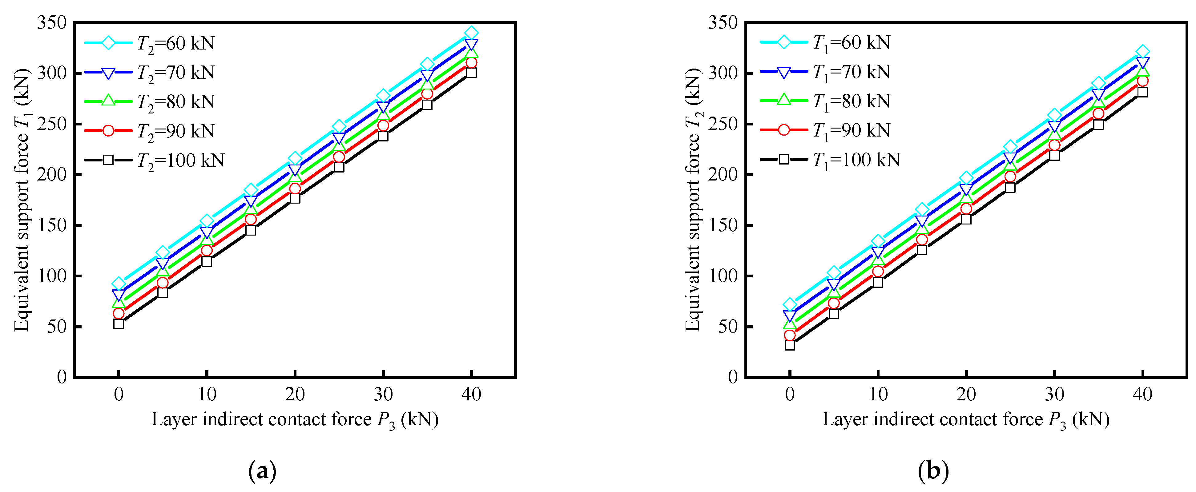
3.2. Influence of Support Strength on Self-Stability of Roof Structure

Combined with the engineering geological conditions of the 1201 working face, the initial calculation parameters of Equation (11) are set as follows: the roof block structure width L is about 7 m, the bolt spacing is 800 mm, the number of roof bolts k is 7, and the average density of rock mass ρ is 2500 kg/m3, the acceleration of gravity g is 9.8 m/s2, the thickness of block r is 1.8 m, and the dip angle of rock stratum θ is 45°. To simplify the calculation, take r1 = r, and the left boundary of block structure is considered as the mining side, under the influence of dynamic pressure, it is easy to separate the top block structure from the coal body and move towards the rock stratum, at this time, the shear force Fs2 can be approximately regarded as 0, which can be obtained by substituting the above parameters into Equation (11):
T 1 [ sin ( α + 11.55 ° ) 0.389 sin α ] + T 2 [ sin ( β 11.55 ° ) + 0.389 sin β ] = 3.86 P 3 + 82.5
It can be seen from Equation (12) that the bolt support parameters are closely related to the layer indirect contact force P3. When P3 = 0, it means that the roof block structure is completely separated from the overlying strata, and the corresponding support force should be the minimum value to maintain the stability of the roof block structure. In order to study the relationship between the indirect contact force P3 and the bolt support strength, the bolt installation angle α and β are assumed 70° and 35°, respectively. Substituting α and β into Equation (12), we can get the variation law of T1 and T2 with P3, as shown in Figure 10.
It can be seen from Figure 10 that the contact force between strata has an important influence on the roof support strength of roadway in large inclined seam, and its influence mode is mainly reflected in three aspects:
(1)
When the support strength of one side arch position is fixed, the support strength of the corresponding other side arch position increases linearly with the increase of indirect contact force of strata.
(2)
When the layer indirect contact force is fixed, the support strength on both sides of the left and right arch has a negative correlation, that is, when P3 is fixed, T1 gradually decreases with the increase of T2, which indicates the reliability of using asymmetric support method to solve the instability of roof block structure in large inclined seam roadway from the mechanical point of view.
(3)
With the gradual increase of T1 and T2, the indirect contact force P3 gradually increases, and the squeezing force of weak structural plane increases, that is, the shear resistance is enhanced. This indicates the feasibility of using a high-strength support system to solve the shear sliding failure of the weak structural plane in the roof of a large inclined roadway from the perspective of mechanics.

4. Control Technology of “High Pre-Stress Asymmetry” in Roadway of Large Inclined Seam

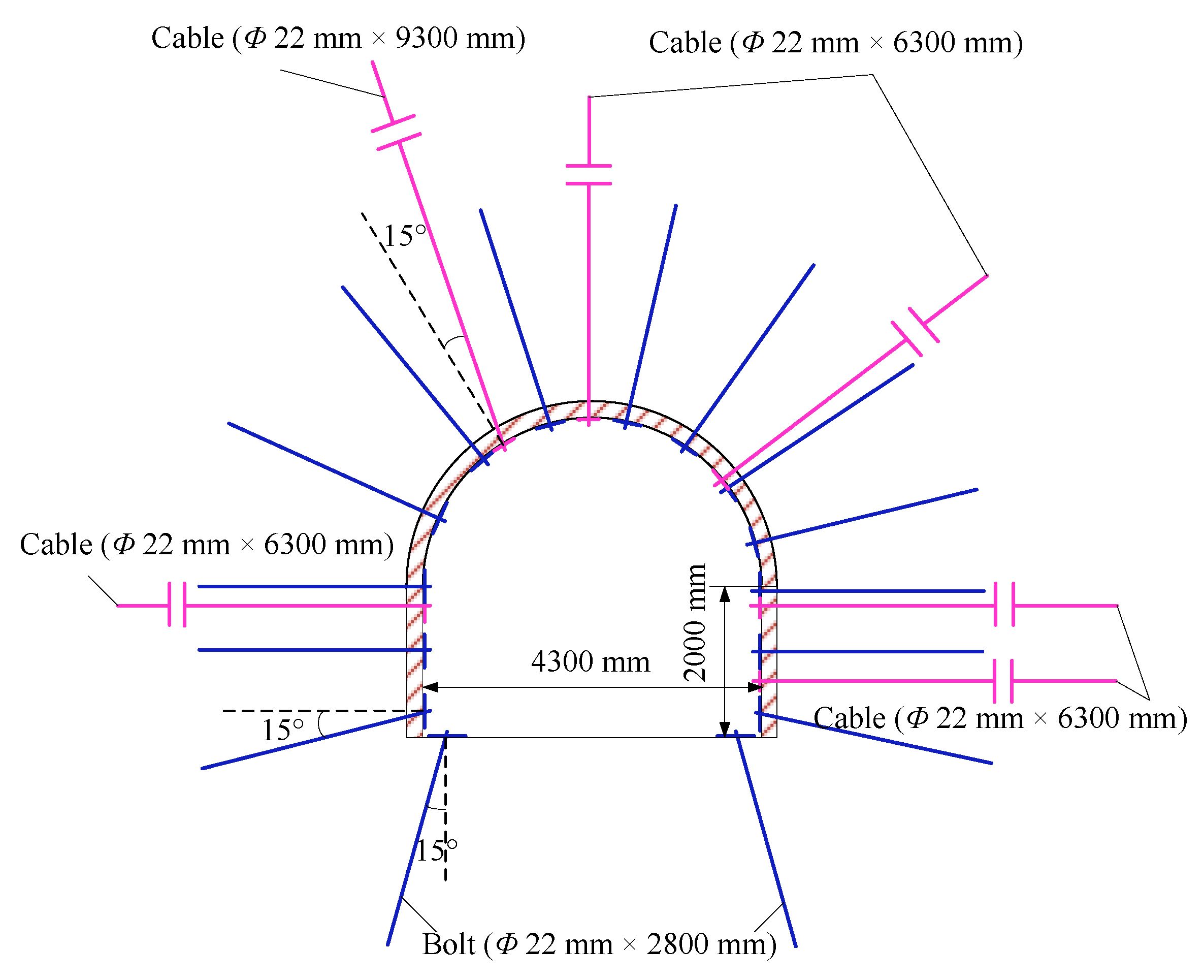
4.1. Design of Surrounding Rock Support Scheme for Roadway in Steep Coal Seam

According to the numerical simulation results, the key points to control the deformation and failure of this kind of roadway are as follows: First, control the shear failure of weak structural plane of roadway roof along the direction of rock dip. Secondly, the support strength of the right spandrels of the roadway is strengthened to reduce the influence of the additional stress caused by the shear slip of the weak structural plane on the deformation of the right spandrels. Thirdly, the high-strength cable is used to bolt the surrounding rock in the stable rock, so that the side and roof are in the state of high-strength compressive stress, so as to prevent the roadway linkage overall instability caused by local tensile shear failure.
According to the characteristics of roadway instability and the rock structure in the steep coal seam, the concept of “high pre-stressed asymmetric” support is put forward. The “asymmetry” is mainly reflected in the asymmetry of support form and support strength. The asymmetry of support form is mainly determined by the structural characteristics of the surrounding rock. Because the design of cable parameters focuses on anchoring the whole structure of surrounding rock in stable rock, the length design should match the structural characteristics of surrounding rock. The asymmetry of support strength is mainly related to the convergence deformation state of surrounding rock. According to the simulation results, considering the condition of weak structural plane slip, the deformation, and failure degree of the middle part of the right spandrels is higher, which should be the key reinforcement area. The specific support parameters of the roadway are designed as follows: φ
(1)
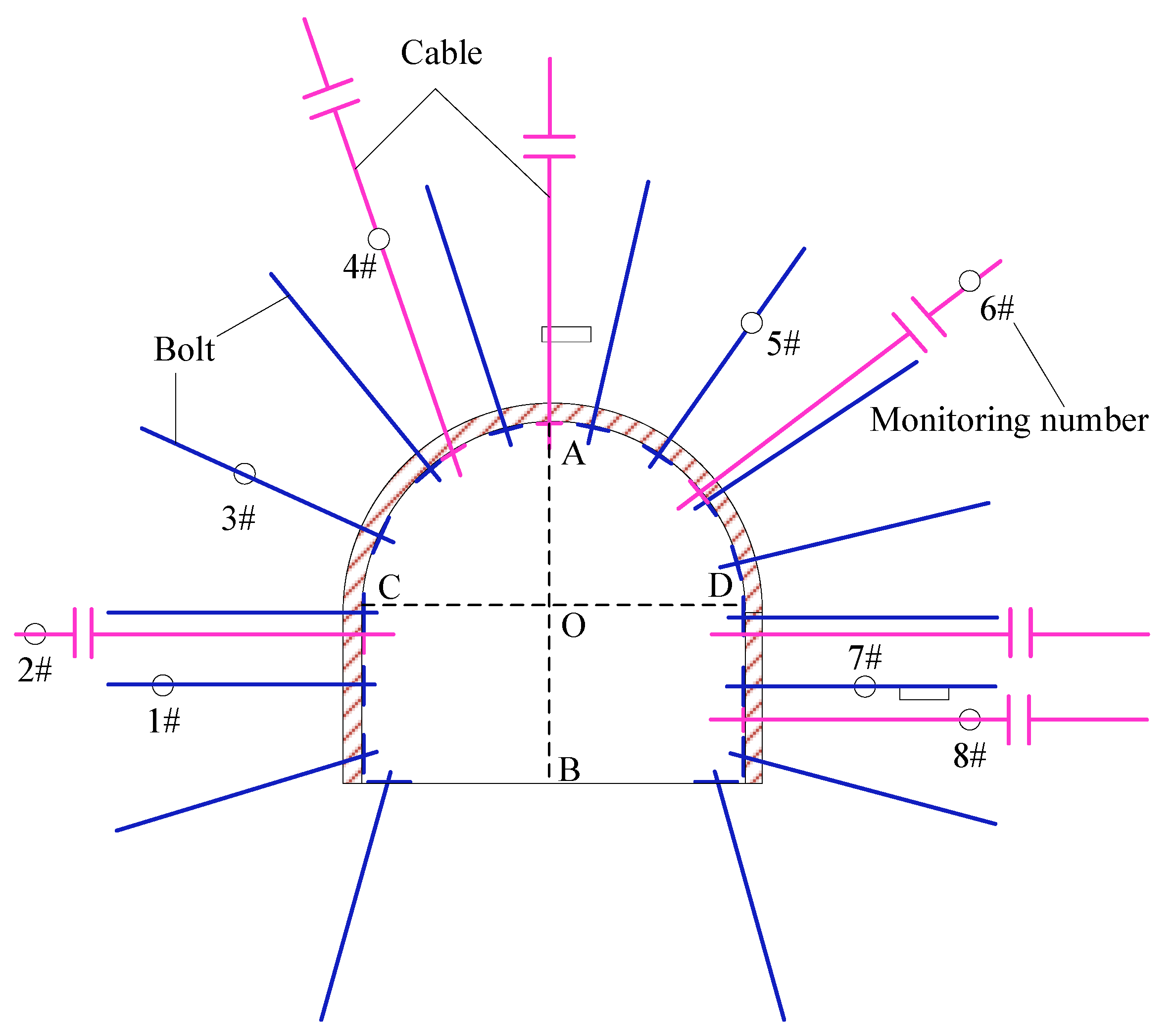
Arch support parameters: The type of the arch bolt is BHR500, the specification is Φ22 mm × L2.8 m left-hand screw steel bolt, and its layout is asymmetric with the centre line of the roadway as the axis, in which three bolts are arranged on the left arch side, and the row spacing is 1.0 m × 8 m, the pre-load is 80 kN, four bolts are arranged at the right arch side, two bolts at the arch shoulder, and the row spacing is 0.8 m × 8 m, the initial pre-load is 90 kN, and the support is strengthened. The material of arch cable is 1 × 19 strands of high strength and low relaxation pre-stressed steel strand, 22 mm in diameter, of which the length of left spandrels cable is 9.3 m and the row spacing is 1.2 m × 1.6 m, inclined 15° for installation, the pre-load is 300 kN, the length of cables at the vault and right spandrels is 6.3 m, and the spacing between rows is 2.0 m × 6 m, the initial pre-load is 350 kN, and three K2335 and two Z2360 resin anchorage agents are used for lengthening anchorage.
(2)
Support parameters of the side: the design of the side bolt is symmetrical distribution, and its specification is the same as that of the roof, three bolts in each row, and the spacing between rows is 0.8 m × 8 m, and the pre-load is 80 kN. One and two cables are arranged on the left side and the right side, respectively, with the length of 6.3 m, the row spacing of 1.6 m and the pre-load of 300 kN.
(3)
Floor support parameters: the length of floor bolt is 2.8 m, the installation position is 0.3 m away from the roadway side, and the pre-load is 80 kN. In addition, the anchor rod in this design adopts end anchorage, and the anchorage length is 1.2 m, and the specific support form of roadway section is shown in Figure 11.

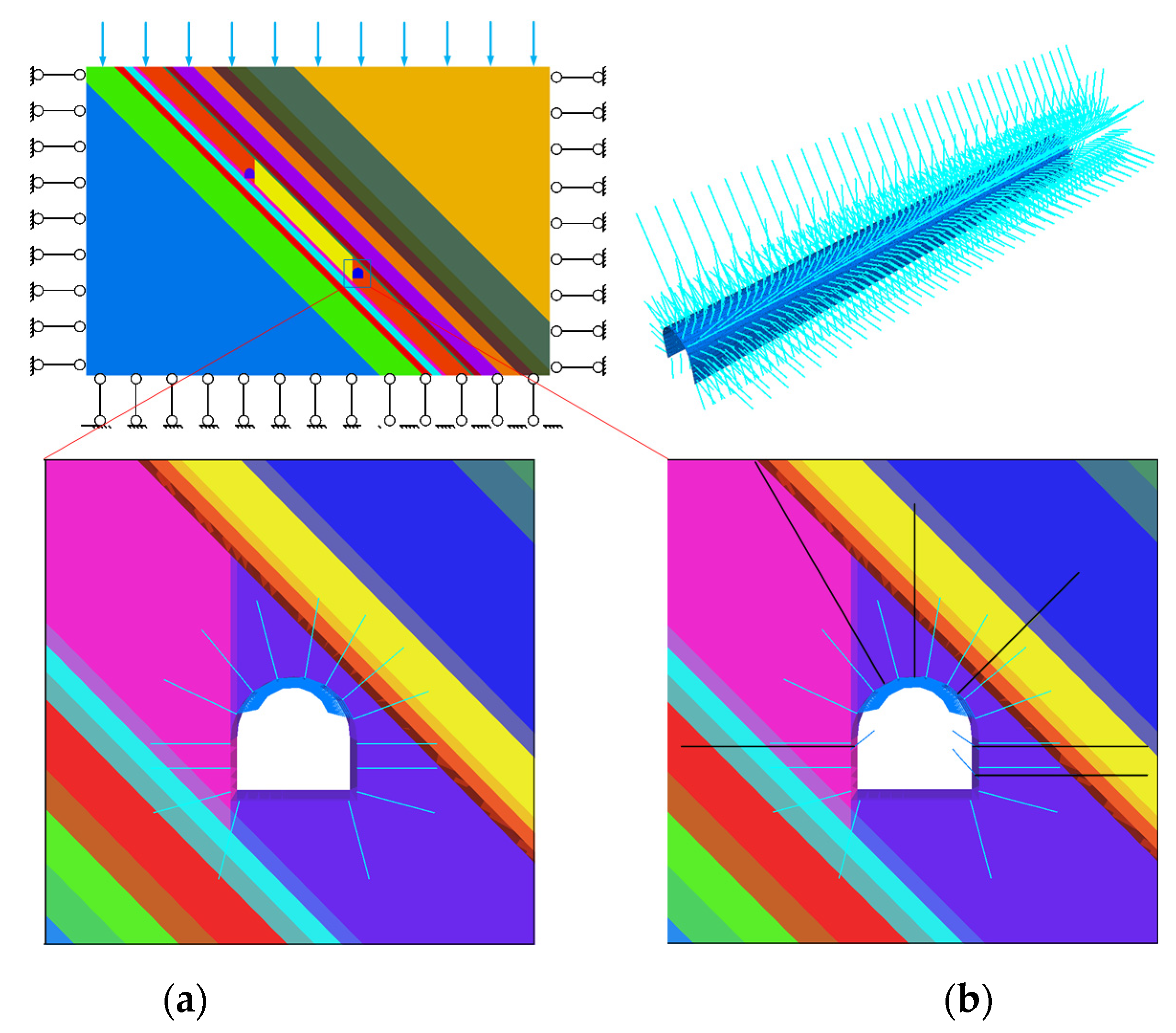
4.2. Establishment of Numerical Calculation Model for Supporting Scheme

The parameters and boundary conditions of the surrounding rock in this simulation are shown in Section 2.2. In addition, cable element is used to express bolt and cable, beam element and shell element are used to express trapezoidal beam, bolt and wire meshes, respectively. Because the steel grade of bolt in this design is BHR500, the elastic modulus of the corresponding anchor rod in the simulation is 2.436 GPa, the yield load is 190 kN, and the elongation is 27.5%. In addition, yield load of 1 × 19 strands of high strength and low relaxation pre-stressed steel strand cable is 483 kN, the elongation is 7%, and the tensile modulus is about 200 GPa. The parameter assignment of the bolt, wire meshes and cable in this simulation is shown in Table 2. It should be noted that in order to effectively play the role of pre-stressing, the connection mode between bolt, cable, and surrounding rock is modified in this simulation, and the rigid connection between them is realized.
In this simulation, Bolt and wire meshes support (scheme I) and bolt, wire meshes and cable combined support (scheme II) are set to simulate and study the shear slip and surrounding rock response of coal-clay weak structural plane under different support schemes before and after mining. It should be noted that scheme II is a scheme I without cable and other supporting parameters are consistent. The numerical model is shown in Figure 12.

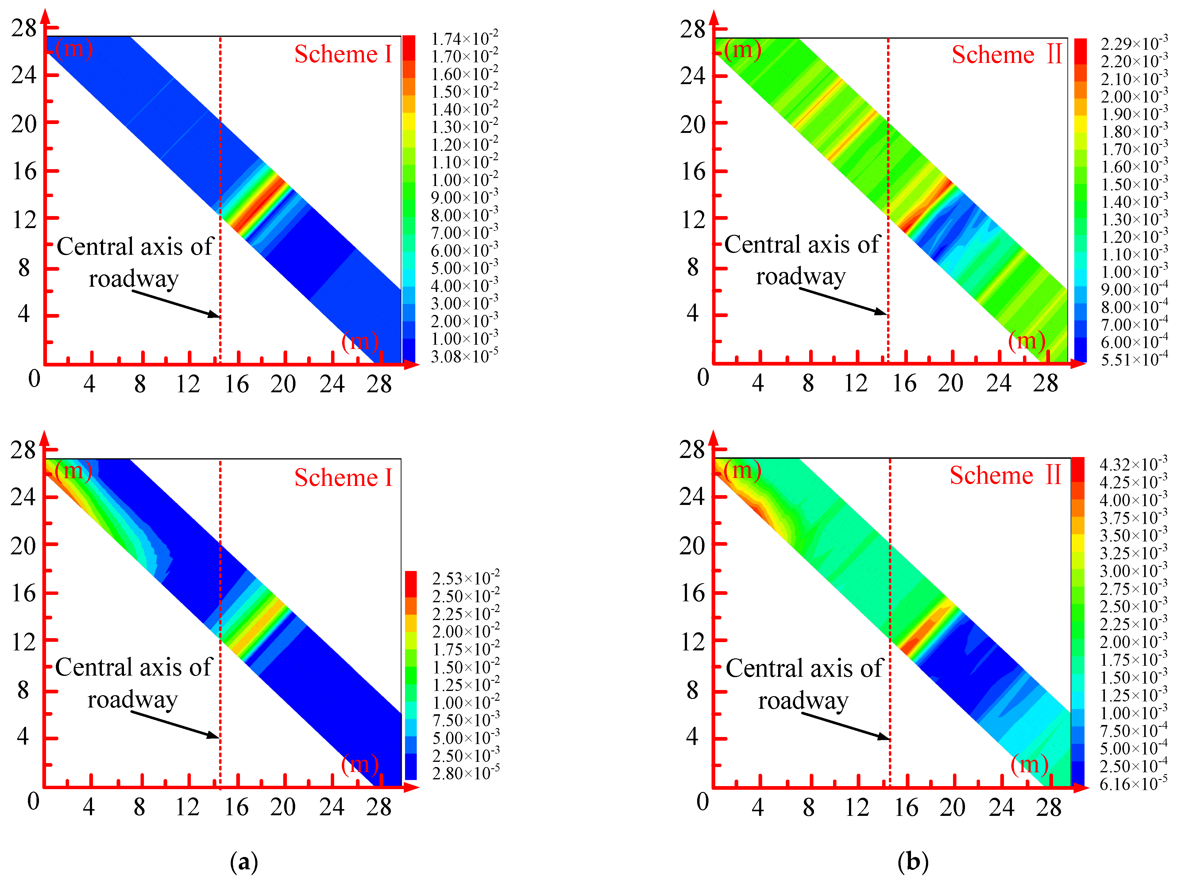
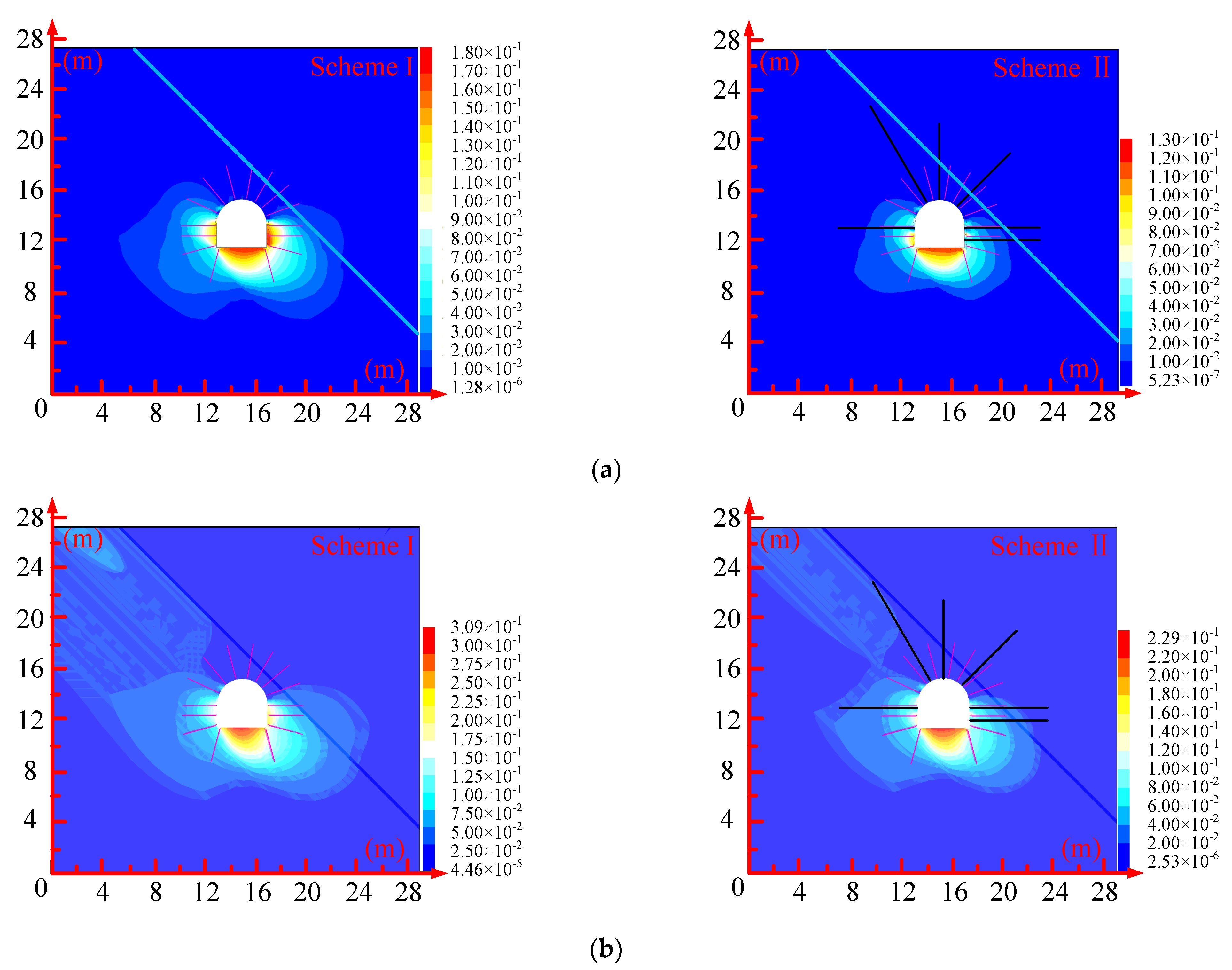
4.3. Influence of Support Scheme on Shear Deformation of Weak Structural Plane in Roadway Roof

Based on the numerical simulation results, the variation curve of the advanced abutment pressure of the working face with the advancing distance of the working face is drawn, as shown in Figure 13. It can be seen from the Figure that the influence range of the advanced abutment pressure of the coal seam is about 20–25 m in front of the working face, and the peak abutment pressure is about 9–11 m in front of the working face, and reflect the influence of mining intensity on the mechanical state of surrounding rock, this simulation selects the roadway section of 10 m in front of the working face after mining 50 m for analysis. The shear displacement nephogram of weak structural plane of roof coal-clay stone under different support schemes before and after mining in 1201 working face is shown in Figure 14.

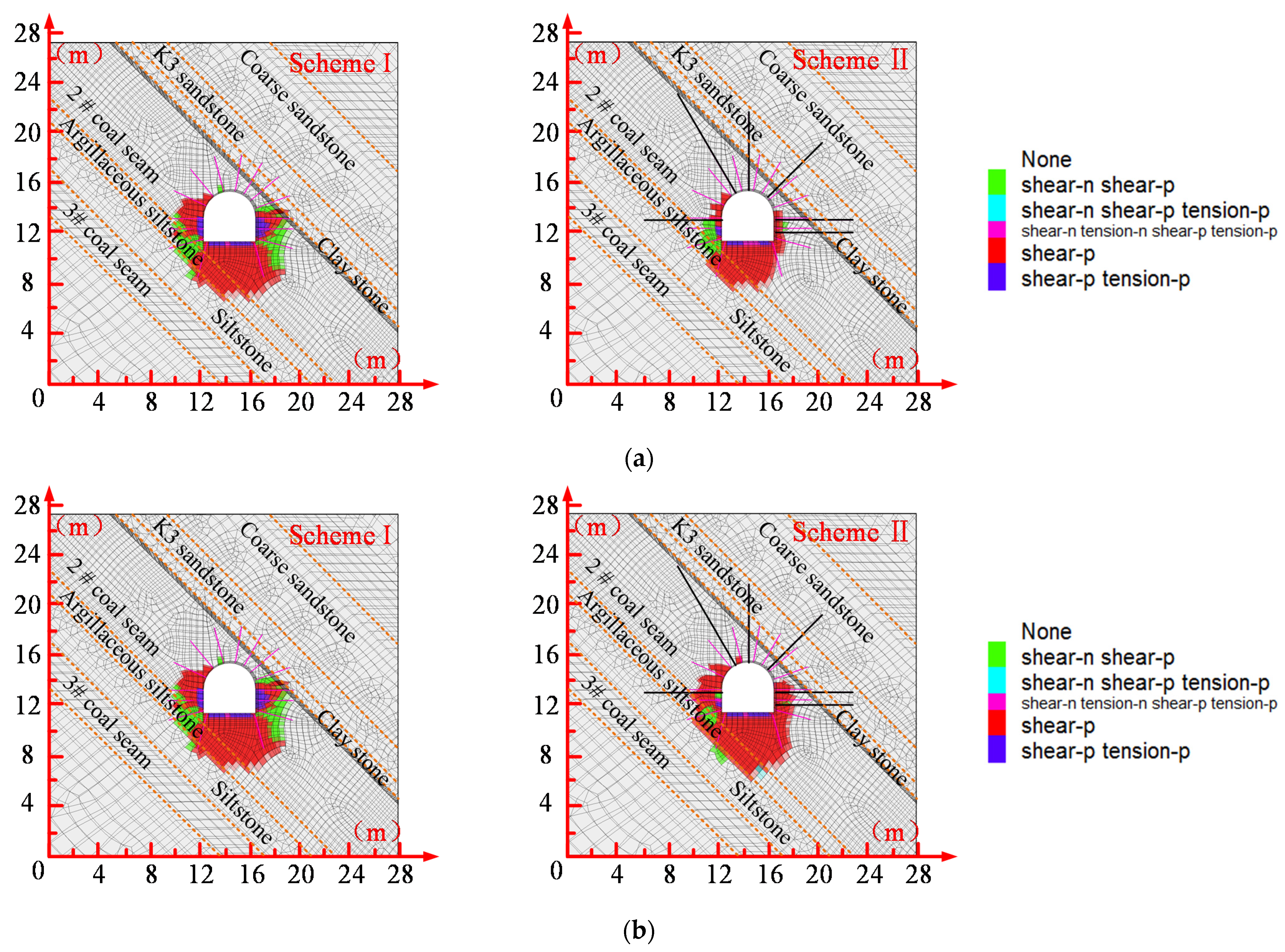
4.4. Influence of Support Scheme on Plastic Zone of Roadway Surrounding Rock

It can be seen from the Figure that the combined support scheme of bolt, wire meshes, and cable has a significant effect on controlling the shear slip of weak structural face of roadway roof, regardless of whether the working face is mined or not. Before mining, compared with the bolt and wire meshes support, the maximum shear displacement of the coal–clay stone weak structure plane is only 2.3 mm, which is reduced by 86.78%, while the maximum shear displacement is 4.3 mm; 83% lower after the face is recovered. The above analysis shows that the combined support of bolt, wire meshes and cable before and after mining can effectively control the shear slip failure of weak structural surface, and then verify the reliability of the combined support scheme of bolt, wire meshes and cable designed with the concept of “high pre-stress asymmetry”.
Figure 15 shows the plastic distribution of surrounding rock under different support schemes before and after mining. It can be seen from the Figure that whether face mining is considered or not, the supporting effect has a significant influence on the distribution of plastic zone of roadway in the big dip seam. Plastic zone of the roadway under bolt and wire meshes support and combined support of bolt, wire meshes and cable is decreasing gradually, and the reduction range is closely related to mining strength. Before and after mining, under the bolt and wire meshes support and combined support of bolt, wire meshes and cable, the plastic zone of the roof of the roadway basically disappeared, which indicates that the two support schemes have a better control effect on the roof. However, the plastic zone of roadway top and floor under bolt and wire meshes support is larger than that of combined support of bolt, wire meshes and cable, and it is beyond the bolting range of bolt, which indicates that the design of the support scheme cannot meet the overall stability requirements of the roadway. Besides the bottom plate, the plastic zone under the combined support of bolt, wire meshes, and cable is basically within the bolting range of bolt. It shows that the high pre-stress effect of cable can effectively control the expansion of the surrounding rock plastic zone in the anchorage part, reduce the loose range of surrounding rock and improve the overall support effect of the roadway.
In addition, the plastic zone of the bottom plate under the combined support of bolt, wire meshes and cable gradually expands along the direction of the rock stratum tendency, and its scope increases gradually. It shows that the mining strength has a significant influence on the floor of the roadway under the support condition, and the bottom drum phenomenon is prominent. Therefore, the floor pipe control should be strengthened in time and the optimization scheme can be adjusted in real-time to meet the mining requirements.

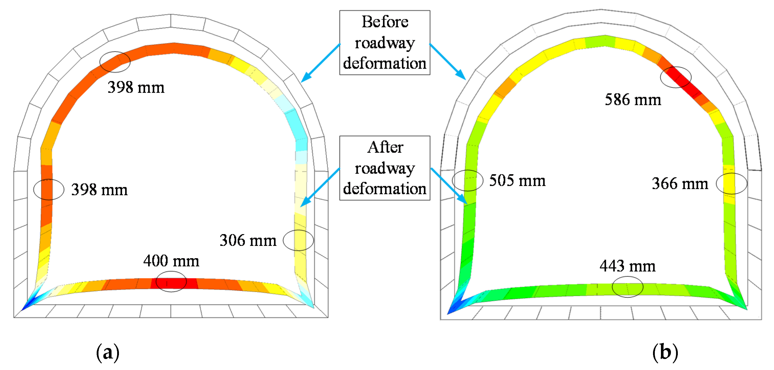
4.5. Influence of Support Scheme on Surrounding Rock Deformation of Roadway

Figure 16 shows the total displacement nephogram of roadway surrounding rock under different support schemes before and after mining. It can be seen from the Figure that no matter whether the working face mining is considered or not, compared with no support, bolt and wire meshes support, and combined support of bolt, wire meshes, and cable can greatly reduce the overall deformation of roadway surrounding rock and reduce the risk of roadway instability, especially in the aspect of roof control, the control effect of the two schemes is better, However, the overall effect of combined support of bolt, wire meshes and cable support is more prominent. In addition, the deformation of the roadway under bolt and wire meshes support presents significant differentiation characteristics. Before mining, the maximum deformation of the left side, right side, and floor of roadway are, respectively 118 mm, 159 mm, and 144 mm higher than that of the roof. After mining, this phenomenon is more prominent, which easily causes serious non-coordination between the support structure and surrounding rock deformation, and then the roadway is damaged first due to local large deformation. Then, the whole structural instability is induced. Before mining, the deformation of surrounding rock under the combined support of bolt, mesh, and cable is at a low level, and the maximum deformation of wall, roof, and the floor is basically controlled within 130 mm, and the deformation difference of each part is small, which reflects the characteristics of coordinated deformation of surrounding rock and support, and is conducive to the long-term stability of surrounding rock structure. After mining, although the deformation of the wall and floor increases slightly, it is less than 230 mm, and the deformation is within the controllable range. Therefore, from the perspective of roadway deformation, the combined support scheme of bolt, wire meshes, and cable based on the concept of “high pre-stressed asymmetric” support can effectively solve the problem of large shear deformation of mining roadway in the large inclined seam.

5. Field Application

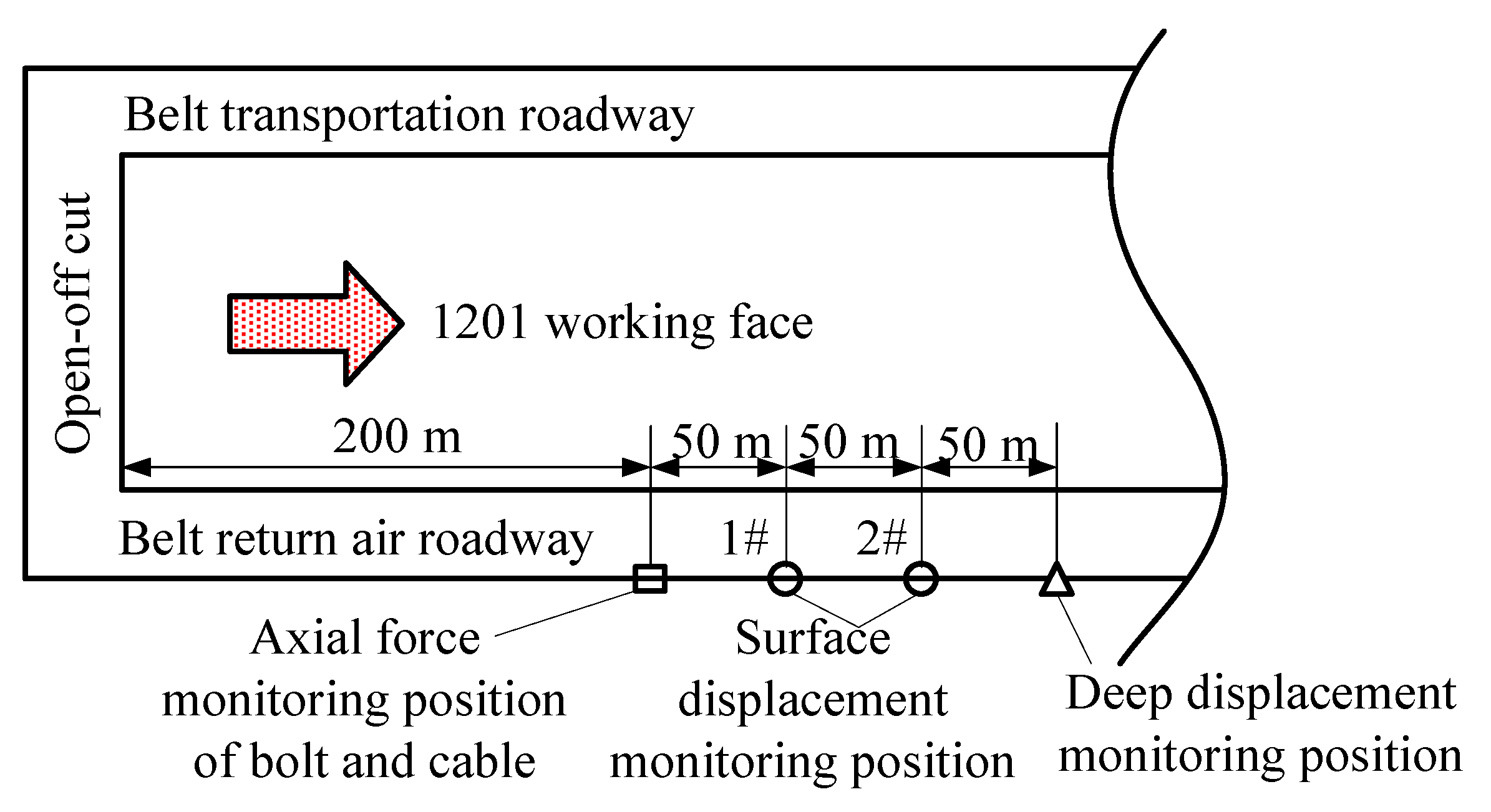
5.1. Monitoring Programme

The support scheme is applied to the site, GMY-400 bolt (cable) load sensor is used to monitor the axial force of bolt and cable, and the monitoring position is 200 m in front of the working face. The cross-point method is used to monitor the roadway surface displacement, and the monitoring position is 250 m and 300 m in front of the working face. NL4200 multi-point displacement meter is used to monitor the deep displacement of the roadway, and the monitoring position is 350 m in front of the working face. The data is recorded manually. Figure 17 and Figure 18 show the monitoring locations.

5.2. Analysis of Monitoring Results

(1)
Analysis of the monitoring results of the axial force of the bolt and cable
Figure 19 shows the curve of axial force of bolt and cable changing with time before mining. It can be seen that the axial force of the bolt rod and bolt cable gradually increases with the increase of time, but some anchors show the characteristics of gradual decrease. For example, after about 100 days of roadway excavation, the axial force of the right spandrels bolt and cable reached 100.07 kN and 370.12 kN, respectively, which increased by 11.1% and 5.7% compared with the initial pre-load, while the axial force of the left spandrels bolt and left side bolt decreased, especially the axial force of left spandrels bolt decreased most significantly, with the maximum decrease of 15.1%, It shows that the bolt failure may occur in this part of the bolt, and the reinforcement support measures must be taken to ensure the original support strength. In addition, when the monitoring point is excavated for 100 days, the bolt axial force is basically stable in the range of 90–100 kN, which is about 47.37–52.63% of the ultimate breaking load, and the cable axial force is basically stable in the range of 320–360 kN, which is about 66.25–74.53% of the ultimate breaking load. The results show that the axial force of bolt and cable still retains a large amount of abundant space, which can guarantee the long-term stability of the roadway under the influence of mining. Furthermore, the reliability of the support scheme is verified from the stress of bolt and cable.
(2)
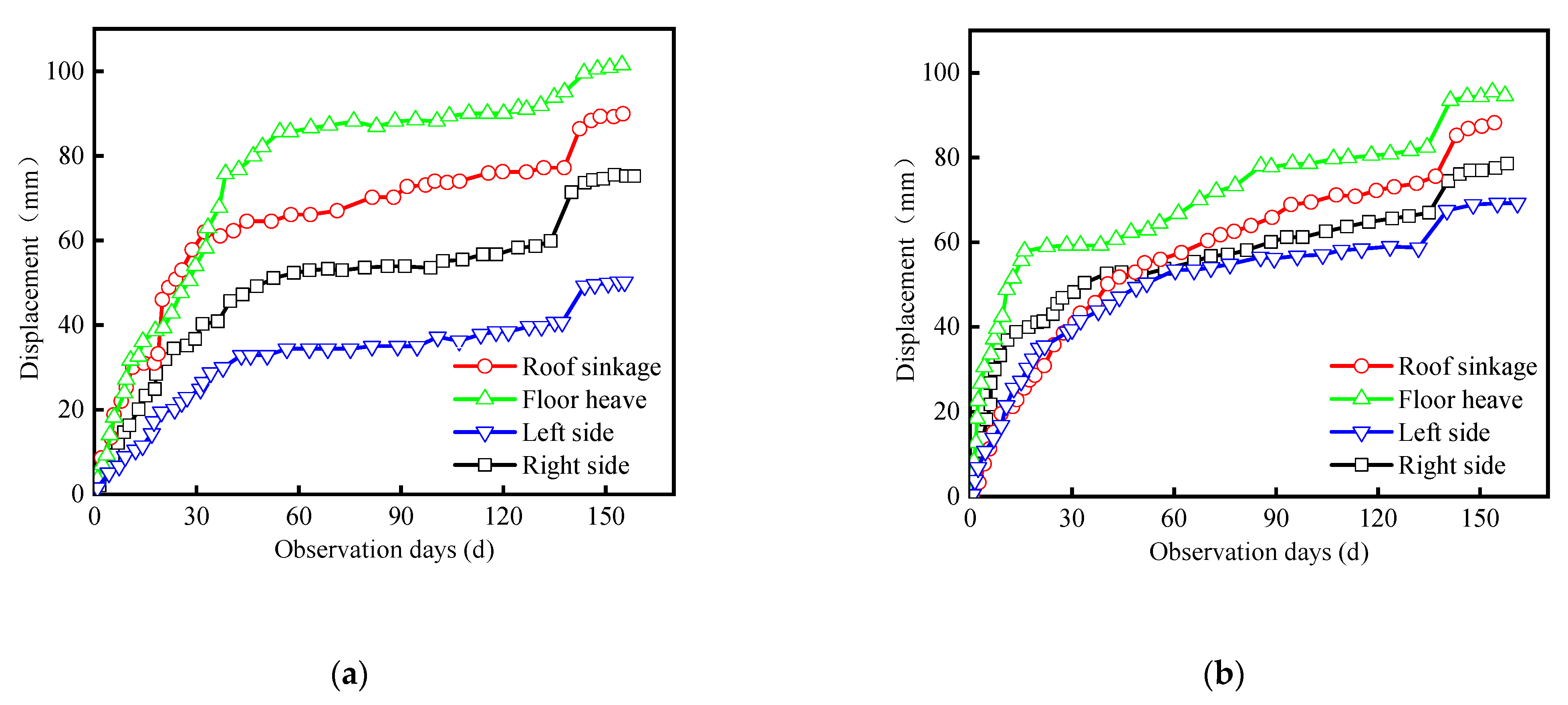
Analysis on monitoring results of roadway surface displacement
During the period from roadway excavation to stopping, the real-time monitoring of roadway surface displacement at No. 1 and No. 2 measuring stations is carried out, and the monitoring results are shown in Figure 20. It can be seen from the Figure that under the influence of roadway excavation disturbance and mining, the roadway deformation of the two stations has experienced about three stages: the stage of a significant increase in deformation, the stage of stable deformation, and the stage of mining influence. In the range of 0–40 days after excavation, the surrounding rock is basically in the stage of a significant increase in deformation. Affected by the excavation disturbance, the deformation of the roadway increases significantly in this stage, but the growth rate gradually decreases. With the continuous increase of roadway deformation, the squeezing force of supporting structure on the surface of surrounding rock increases gradually. When the stress of the surrounding rock reaches the state of stress balance, the roadway begins to enter the stage of stable deformation, which lasts about 90 days. Until the roadway is in the range of mining influence, its deformation begins to increase significantly. In the monitoring time, the maximum displacement of the floor is 101.8 mm, the maximum displacement of the roof is 90.2 mm, and the maximum displacements of the left side and the right side are 69 mm and 88.7 mm, respectively, indicating that the support scheme can effectively control the harmful deformation of surrounding rock.
(3)
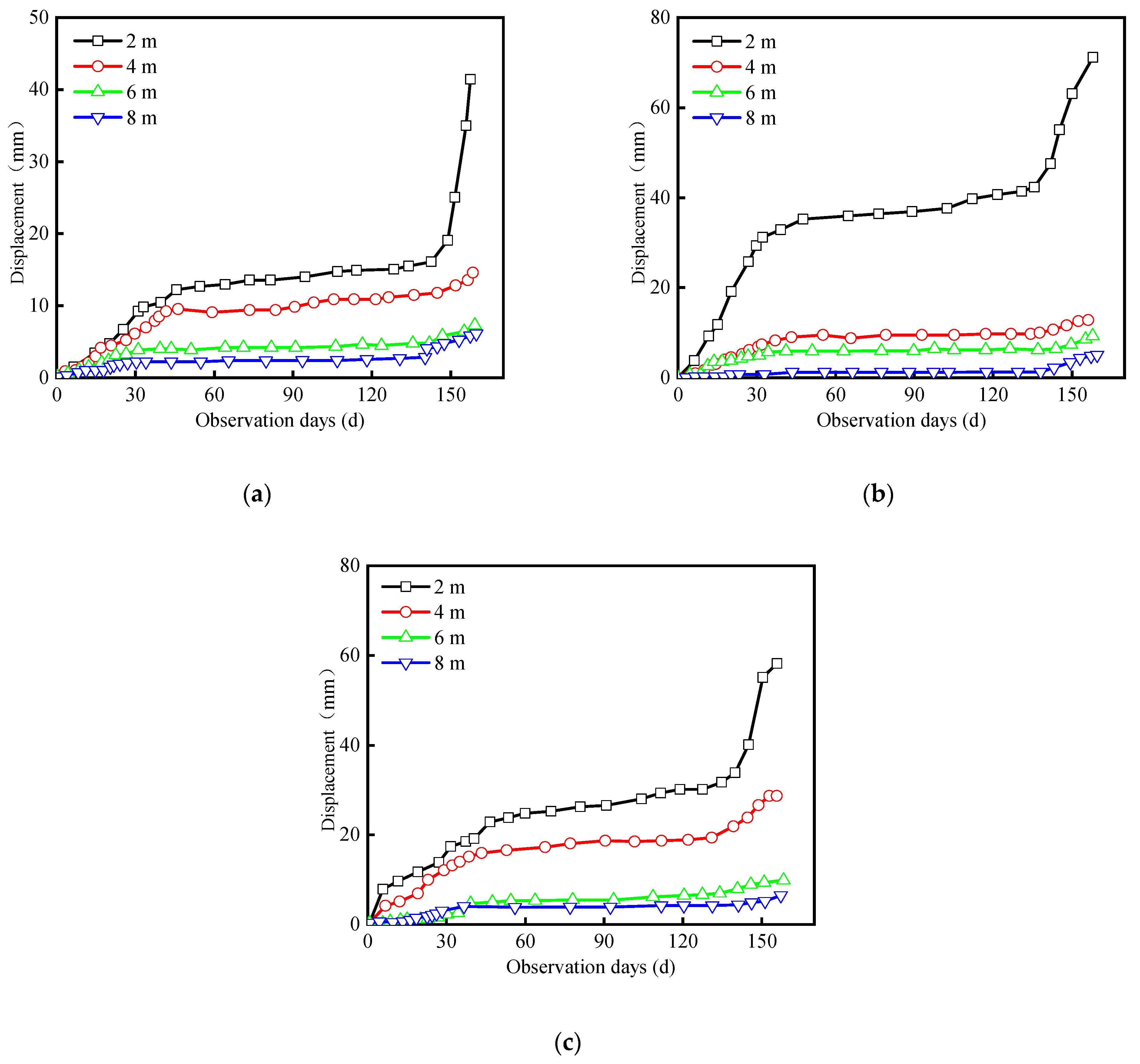
Analysis of monitoring results of roadway deep displacement
Figure 21 shows the curve of displacement of deep surrounding rock of roadway with time. According to the monitoring results, the change of deep displacement of roadway with time can be divided into three stages: the stage of significant increase of deformation, the stage of stable deformation, and the stage of mining influence, which is similar to the surface displacement of the roadway. For example, for the roadway roof, the displacement at 2 m is significantly greater than that at 4 m–8 m, which is mainly because the measuring point at 2 m is located in the coal seam, while the measuring point at 4–6 m is located in K3 sandstone layer, and the measuring point at 8 m is located in the coarse sand layer of the roof, while the strength of the coal body is weak under the pressure shear coupling load, The strength weakening is more obvious under high-strength mining, so the roadway is easy to move along the roof to the free face after excavation, while the strength of the other two strata is higher than that of the coal, and its deformation is smaller as a whole. In general, under the influence of mining, the maximum displacement is only 70.9 mm, which indicates that the design support scheme can effectively control the deep displacement of surrounding rock and weaken the influence of asymmetric load on the deformation of the deep surrounding rock.

6. Conclusions

(1)
When the indirect contact force is constant, the minimum support force of the left and right spandrels is negatively correlated to meet the self-stability of the roof block structure. With the increase of the supporting force of the left and right spandrels, the indirect contact force of the strata increases gradually, that is, the squeezing force of the weak plane of the strata increases, and the shear resistance increases.
(2)
Compared with bolt and wire meshes support, the maximum shear displacement of roof weak layer under combined support of bolt, wire meshes, and cable before and after mining is reduced by 86.78% and 83%, respectively, the maximum total displacement of surrounding rock surface is reduced by 49.22% and 37.1%, respectively.
(3)
The results of field monitoring show that the maximum displacement of the roadway surface under mining influence is 101.8 mm and that of the deep base point is 70.9 mm. The axial force of bolt is about 47.37% to 52.63% of the ultimate breaking load before mining, and the bolt cable axial force is 66.25% to 74.53% of the ultimate breaking load. Moreover, there is enough space for change to adapt to the influence of mining dynamic pressure. The reliability of the support scheme is verified.

Author Contributions

Conceptualization, P.W. and L.C.; methodology, P.W.; software, L.W.; validation, P.W., M.L.; formal analysis, P.W.; investigation, P.W.; resources, W.Z.; data curation, M.L.; writing—original draft preparation, P.W.; writing—review and editing, P.W.; visualization, L.C.; supervision, M.L.; project administration, X.W.; funding acquisition, W.Z. All authors have read and agreed to the published version of the manuscript.

Funding

This research was funded by National Natural Science Foundation of China, grant number 51874278. Foundation Research Project of Jiangsu Province, grant number BK20181357. the “Six Talent Peaks” Project of Jiangsu Province, grant number JNHB-087. the Talent Support Project of Jiangsu Association for Science and Technology, grant number 2019-134. The Independent Research Project of State Key Laboratory of Coal Resources and Safe Mining, grant number SKLCRSM2020X04.

Institutional Review Board Statement

Not applicable.

Informed Consent Statement

Not applicable.

Data Availability Statement

All data, models, or codes that support the findings of this study are available from the corresponding author upon reasonable request.

Acknowledgments

Three anonymous reviewers are thanked for their insightful suggestions and comments, which improved the quality of this manuscript.

Conflicts of Interest

The authors declare no conflict of interest.

References

  1. Zhang, B.; Cao, S.G.; Wang, L.G.; Lu, Y.L. Deformation Failure Mechanism and Support Measurements in Roadway of Steeply Inclined Coal Seam. J. Min. Saf. Eng. 2011, 28, 214–219. [Google Scholar]
  2. Cui, J.; Wang, W.; Yuan, C.; Cao, L.; Guo, Y.; Fan, L. Study on Deformation Mechanism and Supporting Countermeasures of Compound Roofs in Loose and Weak Coal Roadways. Adv. Civil. Eng. 2020, 2020, 1–13. [Google Scholar] [CrossRef]
  3. Ding, K.; Gu, S.; Guo, J.; Gu, D.; Liu, Z.; Wei, B. Numerical investigation on factors affecting stability of roadway surrounding rock with fractured roof. Geotech. Geol. Eng. 2019, 37, 2373–2385. [Google Scholar] [CrossRef]
  4. Yu, Y.; Wang, X.; Bai, J.; Zhang, L.; Xia, H. Deformation mechanism and stability control of roadway surrounding rock with compound roof: Research and applications. Energies 2020, 13, 1350. [Google Scholar] [CrossRef] [Green Version]
  5. Hu, S.X.; Ma, L.Q.; Guo, J.S.; Yang, P.J. Support-surrounding rock relationship and top-coal movement laws in large dip angle fully-mechanized caving face. Int. J. Min. Sci. Technol. 2018, 28, 533–539. [Google Scholar]
  6. Yang, Z.Q.; Liu, C.; Tang, S.C.; Dou, L.M.; Cao, J.L. Rock burst mechanism analysis in an advanced segment of gob-side entry under different dip angles of the seam and prevention technology. Int. J. Min. Sci. Technol. 2018, 28, 55–63. [Google Scholar] [CrossRef]
  7. Qi, X.Y.; Wang, R.J.; Mi, W.T.; Wen, Z.J. Failure Characteristics and Control Technology of Surrounding Rock in Deep Coal Seam Roadway with Large Dip Angle under the Influence of Weak Structural Plane. Adv. Civ. Eng. 2020, 2020, 1–17. [Google Scholar] [CrossRef]
  8. Guo, H.; Yuan, L.; Shen, B.T.; Qu, Q.D.; Xue, J.H. Mining-induced strata stress changes, fractures and gas flow dynamics in multi-seam longwall mining. Int. J. Rock Mech. Min. Sci. 2012, 54, 129–139. [Google Scholar] [CrossRef]
  9. Shen, B.T. Coal Mine Roadway Stability in Soft Rock: A Case Study. Rock Mech. Rock Eng. 2014, 47, 2225–2238. [Google Scholar] [CrossRef]
  10. Sun, X.M.; Wang, D.; Feng, J.L.; Zhang, C.; Chen, Y.W. Deformation control of asymmetric floor heave in a deep rock roadway: A case study. Int. J. Min. Sci. Technol. 2014, 24, 799–804. [Google Scholar] [CrossRef]
  11. Xu, Y.; Chen, J.; Bai, J.B. Control of floor heaves with steel pile in gob-side entry retaining. Int. J. Min. Sci. Technol. 2016, 26, 527–534. [Google Scholar] [CrossRef]
  12. Hai, Y.L.; Hou, S.J.; Long, F.; Han, B. The Theory and Practice of Forepoling Pre-Stressed System Bolt in Preventing the Rib Spalling. Adv. Mater. Res. 2013, 734, 883–887. [Google Scholar]
  13. Wang, J.A.; Jiao, J.L. Criteria of support stability in mining of steeply inclined thick coal seam. Int. J. Rock Mech. Min. Sci. 2016, 82, 22–35. [Google Scholar] [CrossRef]
  14. Niu, S.Q.; Yan, S.S.; Li, Y.; Jia, X.R. Shear instability mechanism and support methods of laminated roof and floor strata in roadway. J. China Coal Soc. 2013, 39, 325–331. [Google Scholar]
  15. Xu, Y.; Pan, K.; Zhang, H. Investigation of key techniques on floor roadway support under the impacts of superimposed mining: Theoretical analysis and field study. Environ. Earth Sci. 2019, 78, 1–14. [Google Scholar] [CrossRef]
  16. Yang, R.; Li, Q.; Li, Q.; Zhu, X. Assessment of Bearing Capacity and Stiffness in New Steel Sets Used for Roadway Support in Coal Mines. Energies 2017, 10, 1581. [Google Scholar] [CrossRef] [Green Version]
  17. Wang, H.; Jiang, C.; Zheng, P.; Li, N.; Zhan, Y. Deformation and failure mechanism of surrounding rocks in crossed-roadway and its support strategy. Eng. Fail. Anal. 2020, 116, 1–17. [Google Scholar] [CrossRef]
  18. Zhang, W.; He, Z.; Zhang, D.; Qi, D.; Zhang, W. Surrounding rock deformation control of asymmetrical roadway in deep three-soft coal seam: A case study. J. Geophys. Eng. 2018, 15, 1917–1928. [Google Scholar] [CrossRef] [Green Version]
  19. Yan, S.; Bai, J.; Li, W.; Chen, J.; Li, L. Deformation mechanism and stability control of roadway along a fault subjected to mining. Int. J. Min. Sci. Technol. 2012, 22, 559–565. [Google Scholar] [CrossRef]
  20. Song, W.; Xu, W.; Du, J.; Wan, H. Stability of workface using long-wall mining method in extremely thin and gently inclined iron mine. Saf. Sci. 2012, 50, 624–628. [Google Scholar] [CrossRef]
  21. Zheng, T.Q.; Guo, D.M.; Zhang, Y.F.; Lv, J. Parameter Optimization and Numerical Analysis of the Special Soft Coal Seam Roadway with Large Inclination Dip. Appl. Mech. Mater. 2012, 256, 1422–1428. [Google Scholar] [CrossRef]
  22. Wang, Y.; Tang, J.; Dai, Z.; Yi, T.; Li, X. Flexible roadway protection technology in medium-thickness coal seam with large dip angle. Energy Sources Part A Recovery Util. Environ. Eff. 2019, 41, 3085–3102. [Google Scholar] [CrossRef]
  23. Zha, W.; Wu, D. Study on Coupling Relationship Between Surrounding Rock Deformation and Support Parameters in Deep Roadway. IOP Conf. Ser. Earth Environ. Sci. 2019, 218, 12118. [Google Scholar] [CrossRef]
  24. Wu, G.; Chen, W.; Jia, S.; Tan, X.; Zheng, P.; Tian, H.; Rong, C. Deformation characteristics of a roadway in steeply inclined formations and its improved support. Int. J. Rock Mech. Min. Sci. 2020, 130, 104324. [Google Scholar] [CrossRef]
  25. Xie, F.X.; Sandro, C. Control of Gob-Side Roadway with Large Mining Height in Inclined Thick Coal Seam: A Case Study. Shock Vib. 2021, 2021, 1–14. [Google Scholar] [CrossRef]
  26. Lu, Y.; Liu, C. Similarity simulation of bolt support in a coal roadway in a tectonic stress field. Min. Sci. Technol. 2010, 20, 718–722. [Google Scholar] [CrossRef]
  27. Hebblewhite, B.K.; Lu, T. Geomechanical behaviour of laminated, weak coal mine roof strata and the implications for a ground reinforcement strategy. Int. J. Rock Mech. Min. Sci. 2004, 41, 147–157. [Google Scholar] [CrossRef]
  28. Lu, G.L.; Wang, C.; Jiang, Y.D.; Wang, H.W. Roadway Supporting Technology in Fully Mechanized Workface with Large Mining Height of Specially Thick Coal Seam in Datong Mining Area. Appl. Mech. Mater. 2012, 204, 1611–1616. [Google Scholar] [CrossRef]
Figure 1. Comprehensive histogram of No. 2 coal seam.
Minerals 11 00881 g001
Figure 2. Numerical model and boundary conditions: (a) schematic diagram of numerical calculation model; (b) schematic diagram of model boundary conditions.
Minerals 11 00881 g002
Figure 3. Three-dimensional numerical calculation model.
Minerals 11 00881 g003
Figure 4. Cloud diagram of total displacement of surrounding rock: (a) no weak structural plane; (b) with weak structural plane.
Minerals 11 00881 g004
Figure 5. Cloud chart of convergence deformation of roadway surface: (a) no weak structural plane; (b) with weak structural plane.
Minerals 11 00881 g005
Figure 6. Cloud diagram of plastic zone: (a) no weak structural plane; (b) with weak structural plane.
Minerals 11 00881 g006
Figure 7. Cloud diagram of shear displacement of weak structural plane.
Minerals 11 00881 g007
Figure 8. Simplified process of structure stable mechanical model of roadway roof with large inclination under support: (a) roadway excavation; (b) simplify the support force of bolt; (c) simplify the roadway roof coal seam into the square block; (d) simplify the overlying strata P3.
Minerals 11 00881 g008aMinerals 11 00881 g008b
Figure 9. Moment balance diagram of top block structure.
Minerals 11 00881 g009
Figure 10. Variation curve of equivalent support force with P3: (a) the equivalent support force T1 varies with P3; (b) the equivalent support force T2 varies with P3.
Minerals 11 00881 g010
Figure 11. Schematic diagram of support for large inclined transport roadway in 1201 working face.
Minerals 11 00881 g011
Figure 12. Numerical simulation model diagram under different support schemes: (a) support of bolt and wire meshes; (b) combined support of bolt, wire meshes, and cable.
Minerals 11 00881 g012
Figure 13. Variation curve of advance support pressure with advancing distance of working face.
Minerals 11 00881 g013
Figure 14. Cloud diagram of shear displacement of weak structure plane of coal-clay stone under different support schemes: (a) nephogram of shear displacement of weak structural plane before mining; (b) nephogram of shear displacement of weak structural plane after mining.
Minerals 11 00881 g014
Figure 15. Cloud chart of surrounding rock plastic zone under different support schemes: (a) plastic zone of surrounding rock before mining; (b) plastic zone of surrounding rock after mining.
Minerals 11 00881 g015
Figure 16. Nephogram of total displacement of surrounding rock under different support schemes: (a) nephogram of total displacement before mining; (b) nephogram of total displacement after mining.
Minerals 11 00881 g016
Figure 17. Distribution diagram of monitoring points of roadway surface displacement and bolt mesh cable stress.
Minerals 11 00881 g017
Figure 18. Layout of monitoring points and stations.
Minerals 11 00881 g018
Figure 19. Monitoring results of bolt rod and cable axial force: (a) monitoring curve of bolt axial force; (b) monitoring curve of cable axial force.
Minerals 11 00881 g019
Figure 20. Variation of deformation of surrounding rock of roadway with monitoring time: (a) No. 1 monitoring section; (b) No. 2 monitoring section.
Minerals 11 00881 g020
Figure 21. Variation curve of displacement of deep surrounding rock of roadway with monitoring time: (a) deep displacement of mining side wall; (b) deep displacement of roof; (c) deep displacement of right side.
Minerals 11 00881 g021
Table 1. Physical and mechanical parameters of coal and rock strata.
Stratum NameDensity
(kg/m3)
Elastic Modulus
(GPa)
Poison’s RatioCohesion
(MPa)
Internal Friction
Angle (°)
Tensile Strength
(MPa)
Overlying rock25003.00.212.3342.6
Medium sandstone26803.90.183.3352.9
Siltstone26902.20.221.2331.4
coal seam14000.790.310.2250.3
pelitic siltstone20901.20.270.8280.5
Clay stone18000.90.290.6260.6
Coarse sandstone24001.40.221.2311.2
K3 sandstone22001.00.232.1321.8
Medium fine sandstone25602.10.312.2332.1
Table 2. Parameters of bolt and cable in numerical simulation.
Cross Sectional Area (mm2)Diameter
(mm)
Elastic Modulus
(GPa)
Yield Force (kN)Elongation
(%)
Pre-Load
(kN)
bolt380.13222.43619027.580–90 kN
cable380.13222004837300–350 kN
Publisher’s Note: MDPI stays neutral with regard to jurisdictional claims in published maps and institutional affiliations.

