Article

Relationship between Chamosite Alteration and Fe-Plugging in Sandstone Pores during Acid In Situ Leaching of Uranium

Department of In Situ Leaching Technology, Beijing Research Institute of Chemical Engineering and Metallurgy, Tongzhou District, Beijing 101149, China
*
Authors to whom correspondence should be addressed.
Minerals 2021, 11(5), 497; https://doi.org/10.3390/min11050497
Submission received: 3 April 2021 / Revised: 27 April 2021 / Accepted: 28 April 2021 / Published: 7 May 2021
(This article belongs to the Section Mineral Processing and Extractive Metallurgy)

Abstract

:
Sandstone pore-plugging is a serious problem that bothers acid in situ leaching (ISL) uranium deposit, but currently, the mechanism of pore-plugging has not attracted much attention. In this study, using X-ray fluorescence, scanning electron microscope, optical microscope, and X-ray diffraction, we present both macro- and micro-evidence of pore-plugging occurred during acid in situ mining of sandstone uranium deposit at Yili Basin, NW (northwest) China. Our study reveals that in comparison with normal sandstones, the plugged sandstones are yellow in color and have relatively high contents of Fe and chamosite. The plugging in studied samples is mainly caused by precipitation of Fe(OH)3 at a pH of 2.0–4.0 for quantitative effect and by precipitation of gypsum (CaSO4·2H2O) as well. Alteration/dissolution of chamosite and to a lesser extent, Fe-bearing microcline and muscovite, may have contributed iron for Fe(OH)3 precipitation. It is suggested that adjustment of injection pH < 2.0 throughout the leaching passage would be an effective way to avoid/minimize this type of sandstone pore-plugging.

1. Introduction

In situ leaching (ISL) uranium is a mining technology that employs chemical reagents (lixiviant: acid or alkaline) to dissolve uranium directly from the host sandstones in confined aquifers and extract uranium from leaching solutions at the surface based on a system of drilling wells [1,2,3,4,5]. ISL has now been the dominant mining method for sandstone type of uranium deposits; meanwhile, 57.4% of the worldwide uranium is produced by ISL [6]. Acid ISL usually using sulfuric acid as lixiviant to extract uranium from the host sandstones is quite popular in some countries such as Kazakhstan, Uzbekistan, Australia, and China, due to the relatively low cost of lixiviant and high leaching rate [6,7,8]. It is well known that a suitable permeability of ore-bearing aquifer (i.e., permeability coefficient at 0.1–10 m/d) is the key element to ensure the success of ISL production [9]. However, the sandstone pore-plugging that reduces the permeability of uranium-bearing aquifer is one of the serious problems commonly encountered in the course of acid ISL. It is suggested that the essence of pore-plugging in acid ISL is newly formed or previously existed materials blocking the sandstone pore-throat or decreasing the size and connectivity of pores [7,8,10,11]. Acid not only releases uranium from U-bearing minerals but also alters gangue minerals, leading to the transportation and precipitation of ions in acidic aqueous environment. Therefore, alteration of minerals under the inappropriate conditions (e.g., too high injection pH) plays a significant role in pore-plugging during acid ISL [12,13]. Presently, numerical simulations and geochemical modeling have been involved in most of studies for sandstone pore-plugging occurring in acid ISL [5,10,11,14,15], but the formation mechanism of the sandstone pore-plugging is still less concerned [13].
In China, the Yili Basin of Xinjiang Province possesses the typical sandstone hosted roll-front uranium deposits, several of which are being in situ mined by the sulfuric acid and hydrogen peroxide as lixiviant and oxidant, respectively [16,17,18]. During ISL operation, in some mining areas, the obvious drop of flow rate of production wells has been monitored, implying the presence of sandstone pore-plugging. Our previous study shows that in plugged mining blocks, the uranium concentration of leaching solutions has dropped from about 100 to <5 mg/L, and the flow rate has also been fallen from 5–6 to 1–2 m3/h (in some cases, even <1 m3/h [19]). The leaching solutions collected from some production wells in these plugged mining blocks are yellow in color and turbid. Nevertheless, the deposit has been industrially in situ leached for a long time, and the formation mechanism of pore-plugging is still difficult to recognize mainly because of the deep burial of the plugged uranium-bearing sandstone aquifer. To understand the essence of plugging, in this study, a drill hole has been drilled to collect samples from plugged horizons of the acid ISL mines in Yili Basin. We have observed direct evidence for pore-plugging occurred in acid ISL. This study is thus of significance to clarify the sandstone pore-plugging mechanism and to develop the corresponding plugging alleviation method.

2. Materials and Methods

The early-middle Jurassic Shuixigou sedimentary group is the main uranium deposit-bearing horizon in Yili Basin, Xinjiang Province, NW China, and is dominated by alluvial fan-braided sandy conglomerate, sandstone, siltstone, shale, and coal measures (Figure 1; [16,20,21]). The studied uranium mineralization in this area mainly occurs as roll-front or tabular shape in interstratified oxidation zones of sandstone aquifers [22,23].
For detailed sampling of plugged rocks, a drill hole was drilled within the mining blocks that had been severely affected by pore-plugging. The targeted drill hole was close to the ISL production wells which have the pumping amounts significantly dropped from a high level of 5 m3/h to <1 m3/h. Eight core samples were collected from the sandstone uranium ore-bearing horizon including uranium mineralized sandstones and rocks above/below the uranium ore (Figure 1). The studied samples were generally gravelly sandstones and/or medium-fine grained sandstones. Macro-observation showed that the uranium mineralized samples have been cemented by yellow materials and the yellow cementation is absent in grey wall rocks. These samples are thus classified as plugged (yellow) and unplugged (grey) types based on their color and are entitled UP-(unplugged) or P-(plugged) in succession from top to bottom of sampling section (Figure 1).
The liquid sample was collected from production well which has the lowest pumping flow rate, as mentioned above. Solids and precipitates in the collected turbid and yellow solutions represent the plugging materials occurring in underground aquifer. We first dried the leaching solutions in an oven with the temperature at 60 °C for at least 24 h. Then, the solids/precipitates left were collected and crushed/ground to pass 200-mesh for chemical analysis.
All eight rock samples were crushed and ground to pass 200-mesh for X-ray fluorescence (XRF) chemical analyses. A PANalytical AxiosMAX XRF (Maveln Panalytical, Beijing, China) was used to analyze the contents of major elements in studied rocks and powders of solids/precipitates collected from solutions.
Typical plugged and other unplugged samples were selected for mineralogical analysis. The whole-rock mineralogical composition was determined by a Rigaku D/max 2500 pc powder X-ray diffractometer (XRD) equipped with Ni-filtered Cu-Kα radiation and a scintillation detector (Rigaku, Beijing, China. All XRD patterns were recorded over a 2θ interval within 2.5–70 degree, with a step-size of 0.02 degree. Quantitative interpretations for the XRD patterns followed the standard in petroleum and natural gas industry [24].
Three polished thin sections (UP-1, P-5, and UP-8, representing samples above, within, and below plugging area) were prepared for microscopic analysis. An Axio Scope, A1 microscope, and a KYKY-2800B scanning electron microscope (SEM) (KYKY TECHNOLOGY CO., LTD, Beijing, China) combined with an energy-dispersive X-ray spectrometer (EDS) (Thermo Fisher, Beijing, China) were employed to perform the micro study of morphology and chemical compositions of the plugging materials. Samples for SEM observation were coated by gold or carbon. During operation, the working voltage and electron beam current of SEM were 20 kV and 100 mA, respectively. All SEM images were captured by a secondary electron detector.

3. Results

Elemental and mineralogical compositions of the studied rock samples are listed in Table 1 and Table 2, respectively. All samples are characterized by high contents of Si (32.5–38.0%), while Al is second high in content ranging from 4.86% to 6.17%, with contents of other elements generally lower than 3% (Table 1). Consistent with macro-observation, Fe in yellow plugged samples is higher than that in grey unplugged samples (Table 1). As for other major elements, variations between plugged and unplugged samples are not significant. However, their variation trends in these two types of rocks can be observed in Figure 2. In Figure 2, contents of major elements Si and K show negative correlations with content of Fe in studied samples, indicating that Si and K have the decreased trends in content from plugged to unplugged samples (Figure 2a,b). While Al shows a totally converse trend (Figure 2c). Other elements are not of concern here because of their too low contents (generally <1%).
Minerals detected by XRD in studied samples comprise quartz, albite, microcline, muscovite, kaolinite, and chamosite (Figure 3; Table 2). While uranium in the studied samples mainly occurrs as pitchblende and coffinite, in some cases, uranium is adsorbed by clay minerals and organic matters [17,25]. Pyrite, gypsum, and mixed-layer illite-smectite have also been identified by SEM and our previous study [13]. Consistent with high content of Si, quartz is the most abundant mineral phase in the studied samples ranging its content from 49% to 55.2%, followed by feldspar (albite and microcline), muscovite, kaolinite, and chamosite (Table 2). The plugged samples have the relatively low content of quartz but the high content of chamosite (Table 2). In Figure 3, the plugged sample (P-5) has the obviously sharper and higher chamosite characteristic peak (marked by a light blue bar) than those of unplugged samples (UP-2 and UP-8). Although distinct in color, in general, the plugged samples have the similar XRD spectra compared to unplugged samples i.e., these two types of sandstones own similar mineral compositions (Figure 3).
Field core macro-observation shows a sharp contact between plugged and unplugged area (Figure 4a). Under a microscope, minerals in the grey sandstones are generally transparent, with yellow-red muscovite in sheet-like shape filling the sandstone pores (Figure 4b). Whereas, in plugged areas, pores have been filled by opaque materials (Figure 4c; corresponding to yellowish brown area in Figure 4a). The SEM-EDS reveals that these opaque materials contain significant content of iron and oxygen (Figure 4d–f and Figure 5a,b). Under SEM, the plugging materials also exist as sheet-/needle-like in shape and cement other large mineral grains (Figure 5a,c). Note that iron is detected in muscovite and feldspar (Figure 5d,e). Gypsum (CaSO4·2H2O) in acid ISL mines is also found covering the surface of rock grains, with the single crystal as tabular and aggregates as daisy-like in shape (Figure 5f,g).
Based on the geochemistry and mineralogy of studied rocks, the slight depletion of Si and K, as well as enrichment of Al in plugged samples, is probably caused by relative enrichment of Fe-plugging materials and chamosite. It is easy to understand that the plugging materials do can influence the contents of elements and minerals, but the influences may not be significant. This is mainly because the plugging occurs only within pore space (which accounts for only a small proportion of total volume).

4. Discussions

4.1. Identification of Plugging Materials

Results of chemical analysis for solids/precipitates in leaching solutions collected from plugged aquifer are shown in Table 3. Iron is the main component (28.38%) of the precipitates, followed by S, Si, Ca, Al, and P, with traces of K, Na, Ti, and Mn. This indicates that the materials plugged the studied samples are mainly iron-bearing materials (probably ferric hydroxide) and a slight amount of gypsum (CaSO4·2H2O). The Si, Al, and extra S and Fe may be ascribed to pyrite and clay particles from ore-bearing aquifer. The fact that the plugging materials are mainly Fe-precipitates can also be inferred by the more yellowish-brown color of plugged sandstones.
Under SEM-EDS, the iron-bearing opaque materials contain 56.0–71.0% iron (averaging 65%) and 25.3–38.0% oxygen (averaging 31.8%; Table 4). In some cases, slight Si and Al are also detected (Al: 0–1.67%; Fe: 0–3.41%; Figure 5c; Table 4). Therefore, the Fe-plugging materials are probably Fe(OH)3 colloids derived from hydrolysis of ferric ions (light element H cannot be detected by EDS) during acid in situ leaching. The content of iron in plugging materials is higher than the ideal mass fraction of Fe(OH)3 (52.3%), indicating the Fe(OH)3 may occur in various forms of isomorphs (e.g., as goethite (FeO(OH)) which has the similar mass fraction of iron (63%)). As inferred from Figure 3 and Table 2, no minerals identified have similar chemical compositions to Fe(OH)3, suggesting that the Fe(OH)3 (or the corresponding isomorphs) may still be amorphous and cannot be detected by XRD. The needle-like occurrence (Figure 5a) is more like goethite, suggesting that the plugging materials are transitional phase from amorphous Fe(OH)3 to goethite.
In a few cases, the plugging is caused by gypsum (CaSO4·2H2O), with the single gypsum crystal as tabular and aggregates as daisy-like in shape (Figure 5f–g). Gypsum aggregates cover the surface of rock grains and thus minimize the size and connectivity of sandstone pores.

4.2. Source of Iron and the Plugging Mechanism

Unlike gypsum that is simply derived from reaction between sulfuric acid and calcium in rocks; however, precipitation of Fe(OH)3 is rather complex. To understand the sandstone pore-plugging mechanism in this case, the source of iron in Fe(OH)3 should be clarified first. Comparison study between plugged and unplugged sandstones in geochemistry and mineralogy has provided the evidence for the source of iron.
Chamosite is supposed to be the primary iron source for precipitation of Fe(OH)3, as it is the only iron-bearing mineral found by XRD. Additionally, compared with other minerals identified, in acid ISL aqueous environment, chamosite more readily reacts with acid [26]. In this study, vertical variation of chamosite shows the same trend as that of Fe (Figure 6). The samples with anomalously high contents of chamosite and Fe are all located in the plugging area (Figure 6). This relationship indicates that chamosite is most likely the primary source of iron for Fe(OH)3.
On the other hand, the rock-forming minerals such as muscovite and feldspar widely distributed in these sandstones (Table 2; Figure 3) may have also supplied iron (at least a small proportion of iron) to Fe(OH)3 in plugged sandstones. EDS data for chemical compositions of feldspar (microcline) and muscovite are listed in Table 4. These muscovite aggregates in Figure 4c are enriched in iron (up to 14.6%; Table 4). While content of iron in the microcline grains ranges from 4.98% to 13.2% (Table 4). In fact, dissolution and alteration of feldspar and muscovite have been observed in acid ISL [13]. In this study, the contact lines between feldspar and Fe(OH)3 colloids are not as clear as quartz (Figure 4d and Figure 5c), which may also be the evidence for feldspar alteration in acid ISL.
At last, although not abundant enough to be detected by XRD, other Fe-bearing minerals commonly associated with redox environment of roll-front uranium deposit including hematite, limonite, siderite, and pyrite [3,12,16,17] should not be neglected. These trace iron-bearing minerals can be potential Fe source by dissolution effect under the acid ISL environment (especially with existence of oxidant [27]).
Both laboratory leaching test and SEM observation have shown that chamosite, feldspar, and muscovite could be altered during acid ISL process [13,26,28,29], and the final alteration products are Fe(OH)3 and Al(OH)3 [26]. In acidic aqueous environment, with the existence of oxidant, these minerals consume sulfuric acid and release Fe3+ into the solutions. According to the laboratory test, during acid ISL, chamosite (and the trace Fe-oxides/-carbonates) should be altered and dissolved first, followed by muscovite and then feldspar. As long as the acid ISL proceeded, reactions between acid and minerals do not terminate and do lead to the local enrichment of the leached ferric ions. Once saturated when leaching condition (pH) changed, these iron ions would precipitate, as Fe(OH)3 (Fe(OH)2 is not supposed to form due to the existence of oxidant) within sandstone pores, thus reducing the size and connectivity of pores.
Previous study has demonstrated that in the Fe3+-U-H2SO4 ISL system, Fe3+ starts to precipitate when pH = 1.5 and ends when pH is 4 but quantitatively precipitates when pH = 2–4 (within this pH window, 97.6% of iron has precipitated) [28]. Field observation data suggest that in the late leaching stage, the leaching solutions have the pH values at 2.5–3.0 (Figure 7) rendering an appropriate environment for significant precipitation of iron as Fe(OH)3 [30]. Chemical reactions between sulfuric acid and these minerals are listed below. Since isomorphism commonly occurrs in minerals, the chemical compositions of these mineral phases may be variable. Impurities in minerals may exist (e.g., Fe in feldspar and muscovite) but are not present in the chemical reactions.
2Fe5Mg5Al2Si3O10(OH)8 (chamosite) + 33H2SO4 +5H2O2 → 4Al3+ + 10Fe3+ + 6Si4+ + 46H2O + 10Mg2+ + 33SO42−
2Na[AlSi3O8] (albite) + H2SO4 + H2O → Al2[Si2O5][OH]4 (kaolinite) + 2Na+ + SO42− + 4SiO2
2K(AlSi3O8) (microcline) + H2SO4 + H2O → Al2[Si2O5][OH]4 (kaolinite) + 2K+ + SO42− + 4SiO2
KAl2(AlSi3O10)(OH)2 (muscovite) + 10H+ → K+ + Al3+ + 3SiO2 + 6H2O
Fe2O3 (hematite) + 3H2SO4 → 2Fe3+ + 3SO42−+ 3H2O
When acid is insufficient, Fe3+ released from the above reactions hydrolyzes at the appropriate pH extent:
Fe3+ + 3H2O → Fe(OH)3 + 3H+ (pH = 2.0–4.0)

4.3. Implication for Antiplugging

Remediation or alleviation of plugging is one of the important issues in ISL production. To increase the flow rate, as well as the rock permeability, a removal or relief technique for plugging is required.
As mentioned above, in acidic solutions, Fe(OH)3 colloids quantitatively precipitate within pH extent of 2.0–4.0 (Figure 7; [19]). It is recommended to adjust leach chemistry to avoid pore-plugging. A possible way to prevent from Fe(OH)3 precipitation is to reduce injection pH to realize values <2.0 throughout the passage of leaching solutions toward the extraction well. In a strong acidic environment, those Fe(OH)3 colloids are then dissolved; meanwhile, permeability of aquifer is thus recovered. Regarding gypsum plugging, the decrease in pH is still a possible measure to minimize CaSO4 precipitation, although it is not as significant as for ferric hydroxide. Thermodynamic simulation has shown that the decrease in injection pH also has a positive effect on the saturation index of gypsum, i.e., gypsum precipitation is reduced at lower pH [31,32]. In a circumstance of low injection pH, interfering effects like pore-plugging by precipitation of ferric hydroxide and gypsum can be minimized/avoided.
Usually, ISL practices recycle the leaching solutions and refortify it by the dosage of sulfuric acid (to adjust the pH to target) and oxidant (for quantitative leaching of U). In this regard, Ca2+ accumulates and gypsum precipitation cannot be avoided in acid ISL. To date, various well stimulations and Ca ions removal methods have been proposed, such as well-flushing, desalination, dilution of injected leach solutions, and adding complex surfactant [33,34,35,36]. However, if the abundance of calcareous minerals is too high, acid ISL becomes economically infeasible due to the severe pore-plugging and extremely high acid consumption. In this case, the CO2 + O2 ISL as a promising mining method has been proposed [36].
Note that both precipitations of Fe(OH)3 and gypsum are attributed to chemical reactions between uranium ore rocks and acid and thus can be assigned to chemical type of pore-plugging. Another physical type of pore-plugging merely caused by particles transportation and accumulation in sandstone aquifers [36] is not the topic of this study.

5. Conclusions

  • The pore-plugging in the course of acid ISL of sandstone uranium deposits in Yili Basin, NW China, is caused by precipitation of Fe(OH)3 and a slight of gypsum (CaSO4·2H2O).
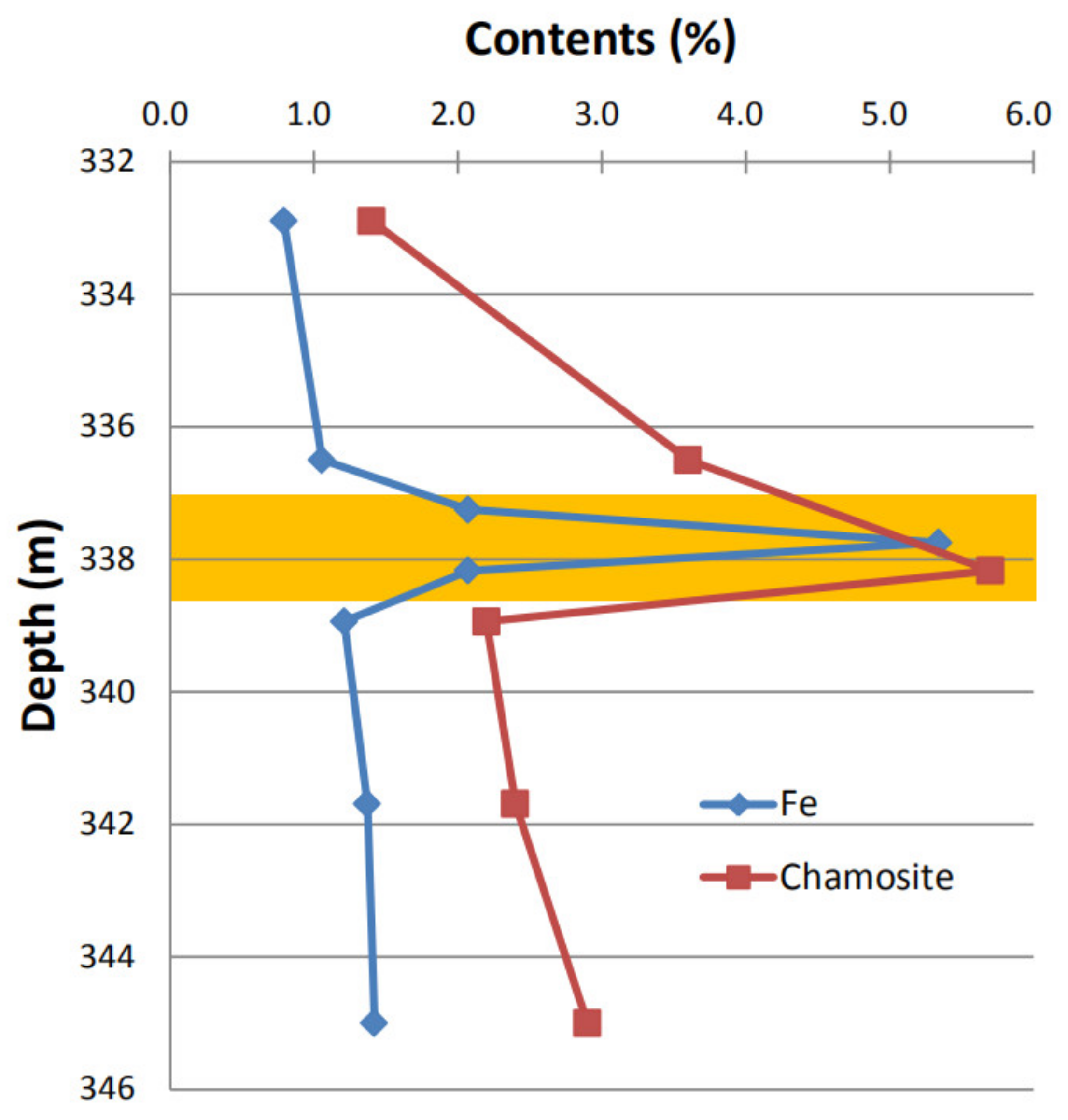
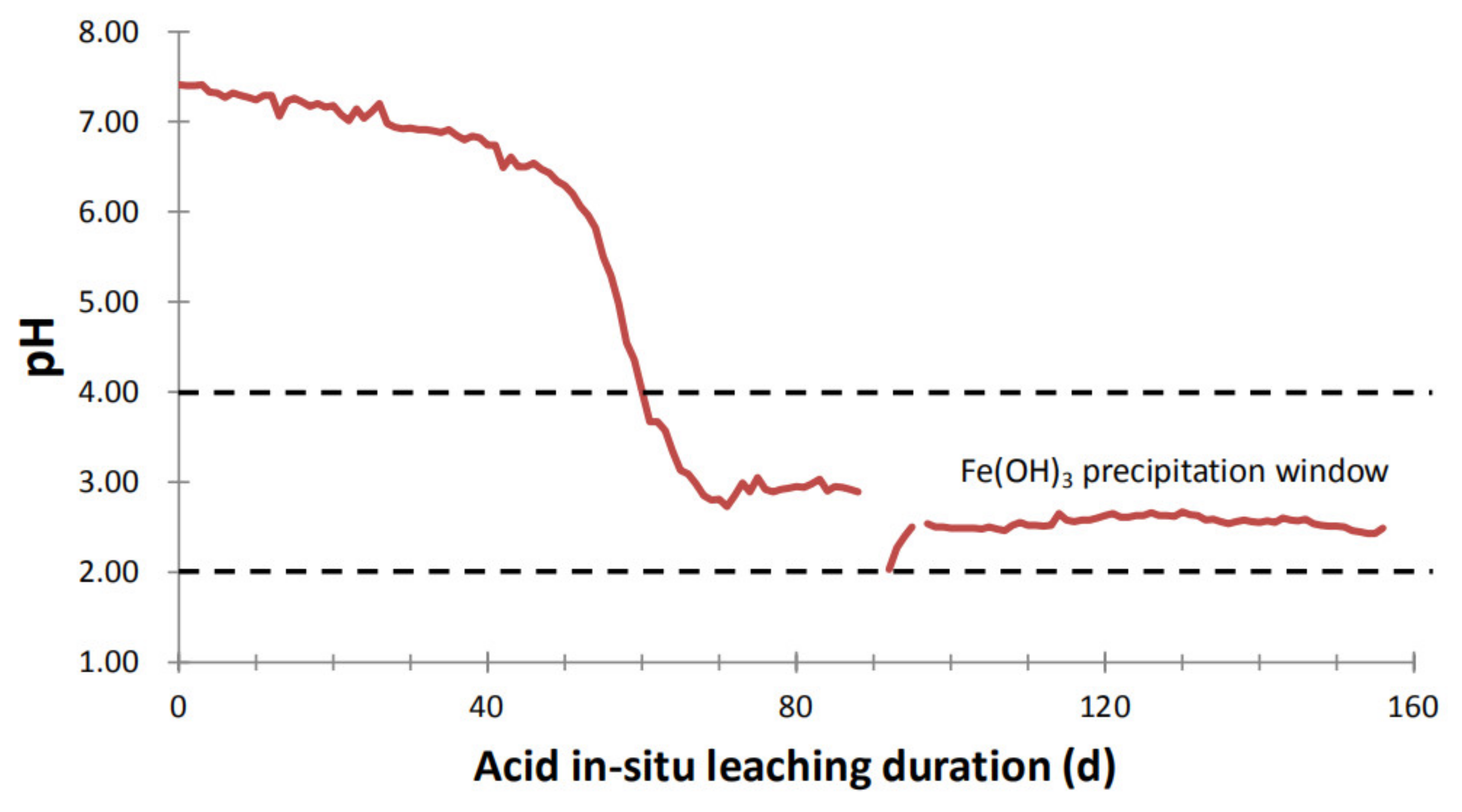
  • Alteration/dissolution of chamosite and to a less extent of Fe-bearing muscovite and feldspar provides Fe for Fe(OH)3 precipitation. Hydrolysis of ferric ions in acidic environment with pH of underground solutions at 2.0–4.0 generates Fe(OH)3 precipitates plugging the sandstone in the way of reducing the size and connectivity of pores.
  • Our study suggests that the main and most simple measure to avoid such Fe(OH)3 plugging would be to sustain pH values of the solutions throughout the leaching passage below 2.0.

Author Contributions

Conceptualization, L.Z.; investigation, P.L.; writing—original draft, L.Z.; writing—review and editing, P.L. All authors have read and agreed to the published version of the manuscript.

Funding

National Natural Science Foundation: 41902181.

Data Availability Statement

Not applicable.

Acknowledgments

This study is supported by the National Natural Science Foundation (No. 41902181) and the CNNC Project for Distinguished Young Scholars.

Conflicts of Interest

The authors declare no conflict of interest.

References

  1. Ilankoon, I.M.S.K.; Tang, Y.; Ghorbani, Y.; Northey, S.; Yellishetty, M.; Deng, X.; McBride, D. The current state and future directions of percolation leaching in the Chinese mining industry: Challenges and opportunities. Miner. Eng. 2018, 125, 206–222. [Google Scholar] [CrossRef] [Green Version]
  2. Seredkin, M.; Zabolotsky, A.; Jeffress, G. In situ recovery, an alternative to conventional methods of mining: Exploration, resource estimation, environmental issues, project evaluation and economics. Ore Geol. Rev. 2016, 79, 500–514. [Google Scholar] [CrossRef]
  3. Abzalov, M.Z. Sandstone-hosted uranium deposits amenable for exploitation by in situ leaching technologies. Appl. Earth Sci. 2012, 121, 55–64. [Google Scholar] [CrossRef]
  4. Zammit, C.M.; Brugger, J.; Southam, G.; Reith, F. In situ recovery of uranium—The microbial influence. Hydrometallurgy 2014, 150, 236–244. [Google Scholar] [CrossRef] [Green Version]
  5. Saunders, J.A.; Pivetz, B.E.; Voorhies, N.; Wilkin, R.T. Potential aquifer vulnerability in regions down-gradient from uranium in situ recovery (ISR) sites. J. Environ. Manag. 2016, 183, 67–83. [Google Scholar] [CrossRef] [Green Version]
  6. Nuclear Energy Agency and International Atomic Energy Agency. Uranium 2020: Resources, Production and Demand; Nuclear Energy Agency: Paris, France, 2020. [Google Scholar]
  7. Mudd, G.M. Critical review of acid in situ leach uranium mining 1. USA and Australia. Environ. Geol. 2001, 4, 390–403. [Google Scholar] [CrossRef]
  8. Mudd, G.M. Critical review of acid in situ leach uranium mining 2. Soviet block and Asia. Environ. Geol. 2001, 41, 404–416. [Google Scholar] [CrossRef]
  9. Que, W.; Tan, Y.; Zeng, Y.; Wang, S. Geochemical Kinetics and Mass Transport of In-Situ Uranium Leaching; China Nuclear Press: Beijing, China, 2002. (In Chinese) [Google Scholar]
  10. Dangelmayr, M.A.; Reimus, P.W.; Wasserman, N.L.; Punsal, J.J.; Johnson, R.H.; Clay, J.T.; Stone, J.J. Laboratory column experiments and transport modeling to evaluate retardation of uranium in an aquifer downgradient of a uranium in-situ recovery site. Appl. Geochem. 2017, 80, 1–13. [Google Scholar] [CrossRef]
  11. Sun, Z.X.; Liu, J.H.; Shi, W.J.; Jiao, X.R. Mechanism of Chemical Plugging during the In-Situ Leach Mining Process in the Shihongtan Uranium Deposit, Xinjiang, China Water-Rock Interaction; ISTP: Guanajuato, Mexico, 2010; pp. 559–563. [Google Scholar]
  12. Pownceby, M.I.; Johnson, C. Geometallurgy of Australian uranium deposits. Ore Geol. Rev. 2014, 56, 25–44. [Google Scholar] [CrossRef]
  13. Zhao, L.; Deng, J.; Xu, Y.; Zhang, C. Mineral alteration and pore-plugging caused by acid in situ leaching: A case study of the Wuyier uranium deposit, Xinjiang, NW China. Arab. J. Geosci. 2018, 11, 707. [Google Scholar] [CrossRef]
  14. Ben Simon, R.; Thiry, M.; Schmitt, J.-M.; Lagneau, V.; Langlais, V.; Bélières, M. Kinetic reactive transport modelling of column tests for uranium In Situ Recovery (ISR) mining. Appl. Geochem. 2014, 51, 116–129. [Google Scholar] [CrossRef]
  15. Sun, Z.X.; Gao, B.; Liu, J.H.; Shi, W.J. Geochemical modelling of fluid-rock interaction during acid ISL uranium mining in SHT Uranium Deposit, NW-China. Geochim. Cosmochim. Acta 2009, 73, A1294. [Google Scholar]
  16. Hou, B.; Keeling, J.; Li, Z. Paleovalley-related uranium deposits in Australia and China: A review of geological and exploration models and methods. Ore Geol. Rev. 2017, 88, 201–234. [Google Scholar] [CrossRef]
  17. Min, M.; Chen, J.; Wang, J.; Wei, G.; Fayek, M. Mineral paragenesis and textures associated with sandstone-hosted roll-front uranium deposits, NW China. Ore Geol. Rev. 2005, 26, 51–69. [Google Scholar] [CrossRef]
  18. Zhou, Y.; Li, G.; Xu, L.; Liu, J.; Sun, Z.; Shi, W. Uranium recovery from sandstone-type uranium deposit by acid in-situ leaching—An example from the Kujieertai. Hydrometallurgy 2020, 191, 105209. [Google Scholar] [CrossRef]
  19. Li, P.; Liu, G.; Duan, B.; Feng, G.; Shao, Y.; Zhou, J. Analysis on the problems of high acid consumption and low uranium concentration leachates during in-situ leaching for a deposit in Xinjiang. Uranium Min. Metall. 2018, 37, 26–31, (In Chinese with English abstract). [Google Scholar]
  20. Dai, S.; Yang, J.; Ward, C.R.; Hower, J.C.; Liu, H.; Garrison, T.M.; French, D.; O’Keefe, J.M.K. Geochemical and mineralogical evidence for a coal-hosted uranium deposit in the Yili Basin, Xinjiang, northwestern China. Ore Geol. Rev. 2015, 70, 1–30. [Google Scholar] [CrossRef]
  21. Zhang, X.; Nie, F.-J.; Xia, F.; Zhang, C.-Y.; Feng, Z.-B.; Ullah, R.; Zhang, P.-F. Provenance constraints on the Xishanyao Formation, southern Yili Basin, northwest China: Evidence from petrology, geochemistry, and detrital zircon U-Pb geochronology. Can. J. Earth Sci. 2018, 55, 1020–1035. [Google Scholar] [CrossRef]
  22. Yue, S.; Wang, G. Relationship between the hydrogeochemical environment and sandstone-type uranium mineralization in the Ili basin, China. Appl. Geochem. 2011, 26, 133–139. [Google Scholar] [CrossRef]
  23. Song, H.; Ni, S.; Chi, G.; Zhang, C.; Hou, M.; Liu, H.; Wang, G.; Yan, W. Systematic variations of H-O-C isotopes in different alteration zones of sandstone-hosted uranium deposits in the southern margin of the Yili Basin (Xinjiang, China): A review and implications for the ore-forming mechanisms. Ore Geol. Rev. 2019, 107, 615–628. [Google Scholar] [CrossRef]
  24. SY/T 5163-2010. Analysis Method for Clay Minerals and Ordinary Non-Clay Minerals in Sedimentary Rocks by the X-ray Diffraction; Petroleum Industrial Publishing House: Beijing, China, 2010. (In Chinese) [Google Scholar]
  25. Min, M.; Luo, X.-Z.; Mao, S.-L.; Wang, Z.-Q.; Wang, R.C.; Qin, L.-F.; Tan, X.-L. An excellent fossil wood cell texture with primary uranium minerals at a sandstone-hosted roll-type uranium deposit, NW China. Ore Geol. Rev. 2001, 17, 233–239. [Google Scholar] [CrossRef]
  26. Niu, Y.; Yao, Y.; Wen, Z.; Xu, G. Simulation and Control of In-Situ Uranium Leaching; Beijing Research Institute of Chemical Engineering and Metallurgy: Beijing, China, 2016. (In Chinese) [Google Scholar]
  27. Chandra, A.P.; Gerson, A.R. The mechanisms of pyrite oxidation and leaching: A fundamental perspective. Surf. Sci. Rep. 2010, 65, 293–315. [Google Scholar] [CrossRef]
  28. Wen, Z.; Yao, Y.; Niu, Y.; Xu, G.; Xie, T.; He, K.; Zhang, C. Formation of precipitation and its effect on uranium in-situ leaching process by acid. Uranium Min. Metall. 2015, 34, 171–177, (In Chinese with English abstract). [Google Scholar]
  29. Yuan, G.; Cao, Y.; Gluyas, J.; Jia, Z. Reactive transport modeling of coupled feldspar dissolution and secondary mineral precipitation and its implication for diagenetic interaction in sandstones. Geochim. Cosmochim. Acta 2017, 207, 232–255. [Google Scholar] [CrossRef] [Green Version]
  30. Baumgartner, J.; Faivre, D. Iron solubility, colloids and their impact on iron (oxyhydr)oxide formation from solution. Earth-Sci. Rev. 2015, 150, 520–530. [Google Scholar] [CrossRef]
  31. Rosenberg, Y.O.; Reznik, I.J.; Zmora-Nahum, S.; Ganor, J. The effect of pH on the formation of a gypsum scale in the presence of a phosphonate antiscalant. Desalination 2012, 284, 207–220. [Google Scholar] [CrossRef]
  32. Shukla, J.; Mohandas, V.P.; Kumar, A. Effect of pH on the Solubility of CaSO4·2H2O in Aqueous NaCl Solutions and Physicochemical Solution Properties at 35 °C. J. Chem. Eng. Data 2008, 53, 2797–2800. [Google Scholar] [CrossRef]
  33. Tan, K.; Li, C.; Liu, J.; Qu, H.; Xia, L.; Hu, Y.; Li, Y. A novel method using a complex surfactant for in-situ leaching of low permeable sandstone uranium deposits. Hydrometallurgy 2014, 150, 99–106. [Google Scholar] [CrossRef]
  34. Espenscheid, W.F.; Heilweil, I.J.; Yan, T.Y. Calcite Control in an In Situ Leach Operation. US Patent US 4,103,963, 1 August 1978. [Google Scholar]
  35. Yan, T.Y. Calcite Removal from Carbonated Water—Uranium in Situ Leaching System. Min. Metall. Explor. 1984, 1, 130–135. [Google Scholar] [CrossRef]
  36. Su, X.; Wang, H.; Liu, N. CO2+O2 In-Situ Uranium Leaching; China Nuclear Energy Press: Beijing, China, 2016. (In Chinese) [Google Scholar]
Figure 1. The cross-section of studied uranium ore horizon showing the sampling position.
Minerals 11 00497 g001
Figure 2. Correlations between the contents of Si, K and Al, and Fe in studied samples: (a) negative correlation between Si and Fe; (b) negative correlation between K and Fe; (c) positive correlation between Al and Fe.
Minerals 11 00497 g002
Figure 3. XRD patterns for typical pore-plugged (P-) sandstone, and the unplugged (UP-) samples above and below the ore horizon showing their similar mineralogical compositions, d values in angstrom. Abbreviations Qtz, Kao, Cha, Ms, Mic, Alb, and Fds indicate quartz, kaolinite, chamosite, muscovite, microcline, albite, and feldspar, respectively.
Minerals 11 00497 g003
Figure 4. Macro- and micro-images for studied sandstone: (a) macro-observation showing the distinct yellow plugged area in sandstone (from [19]); (b) reddish-yellow sheet-like muscovite in pores (cross-polarized transmitted light); (c) opaque materials surrounding quartz grains (polarized transmitted light); (d) SEM enlarged image for central area in (c); and (e) and (f) are elemental mapping spectra for Si and Fe, respectively. Abbreviations are the same as in Figure 3.
Minerals 11 00497 g004
Figure 5. SEM images for studied sandstones: (a) needle-/network-like Fe(OH)3 colloids; (b) EDS spectrum for the cross in (a); (c) quartz, feldspar (microcline), and muscovite grains cemented by colloidal Fe(OH)3; (d) EDS spectrum for muscovite marked by the spot in (b); (e) EDS spectrum for feldspar (microcline) marked by a cross in (b); (f) daisy-like gypsum aggregates covering the surface of quartz grain; and (g) enlargement of rectangle in (f) showing the tabular gypsum single crystals. Abbreviations are same as in Figure 3. Gold and carbon shown in EDS spectra are due to the gold- and carbon-coating before SEM operation.
Minerals 11 00497 g005
Figure 6. Vertical variations of contents of chamosite and Fe in studied samples. The orange bar indicates the location of Fe-plugging as revealed by geological description of core rocks.
Minerals 11 00497 g006
Figure 7. Variation of pH value of leaching solutions from the acid ISL mine (modified from [19]).
Minerals 11 00497 g007
Table 1. The contents of major element in studied samples. Samples are entitled UP-(unplugged) or P-(plugged) in succession from top to bottom of sampling section.
Sample LocationSamplesSiTiAlFeMnMgCaNaKPS
Unplugged areaUP-137.90.135.270.790.010.210.220.802.820.030.18
UP-237.90.134.911.060.010.280.310.642.730.020.20
Plugged samplesP-335.40.246.172.070.020.450.290.692.520.030.54
P-432.50.266.155.340.020.680.290.552.420.030.44
P-535.90.215.872.070.020.430.250.652.610.030.22
Unplugged areaUP-638.00.145.351.210.010.320.220.682.540.020.18
UP-736.80.135.251.370.010.300.240.652.510.020.19
UP-837.70.124.861.420.010.270.210.612.460.020.23
Table 2. Quantitative mineralogical compositions of selected samples, sample titles as in Table 1.
Sample LocationSamples/MineralsQuartzAlbiteMicroclineMuscoviteKaoliniteChamosite
UnpluggedUP-150.916.515.79.16.41.4
UP-24913.914.59.69.43.6
PluggedP-544.613.516.010.49.75.7
UnpluggedUP-652.48.918.97.510.12.2
UP-749.913.520.55.28.52.4
UP-855.28.316.38.19.32.9
Table 3. Contents of elements of solids in groundwater (from [19]) collected from plugging horizon.
ElementsSiAlFeCaMgKNaSTiMnP
Content (%)5.964.4828.385.790.630.570.159.850.120.031.44
Table 4. EDS data for Fe-plugging materials, feldspar, and muscovite in plugged samples.
Elements/Contents (%)OMgAlSiKTiFe
Fe-plugging materials36.8--1.37--61.8
33.7-0.693.41--62.2
28.5-0.141.79--69.6
32.0-0.362.44--65.2
25.3-1.042.69--71.0
29.3--1.70--69.0
32.8-0.673.07--63.4
38.0-1.674.40--56.0
30.1-0.42.32--67.2
Feldspar39.3-12.730.04.79-13.2
56.4-3.9231.12.30-6.23
53.7-13.320.66.27-6.15
57.5-12.119.55.85-4.98
Muscovite43.0-17.725.410.4-3.52
55.1-8.8816.64.78-14.6
42.6-15.118.716.0-7.62
47.91.1213.221.010.22.054.51
37.8-18.823.010.2-10.2
Publisher’s Note: MDPI stays neutral with regard to jurisdictional claims in published maps and institutional affiliations.

