Article

Influence of Weak Interlayer on the Mechanical Performance of the Bolted Rock Mass with a Single Free Surface in Deep Mining

1
School of Civil Engineering, Henan Polytechnic University, Jiaozuo 454003, China
2
State Key Laboratory for Geomechanics and Deep Underground Engineering, China University of Mining and Technology, Xuzhou 221116, China
3
Department of Civil Engineering, Monash University, Clayton, VIC 3800, Australia
*
Authors to whom correspondence should be addressed.
Minerals 2021, 11(5), 496; https://doi.org/10.3390/min11050496
Submission received: 23 March 2021 / Revised: 3 May 2021 / Accepted: 5 May 2021 / Published: 7 May 2021

Abstract

:
The existence of the weak interlayer in the roadway surrounding rock mass presents a huge threat to the stability of the underground structure and the safety of mining engineering. By the characteristics of strong adaptability, superior anchoring effect and high efficiency of construction, rock bolt has been widely applied in mine reinforcement. However, the influence of the weak interlayer on the compressive performance of the bolted rock mass is still poorly understood due to the challenges in constructing an efficient experimental platform and complex testing processes. Here, we used the self-developed test system to investigate the influence of the thickness, uniaxial compressive strength, and dip angle of the weak interlayer on the compressive behavior of the bolted rock mass with a single free surface. The results show that the weak interlayer has a great weakening effect on the peak strength and elastic modulus of the specimens due to its low mechanical properties, as well as influencing the crack distribution and failure mode of the samples. As the strength of the weak interlayer is lower than 1.27 MPa, the thickness exceeds 20 mm, and the dip angle exceeds 15°, the synergistic bearing effect will be significantly reduced and affect the mechanical performance of the specimens. The evolution of the bolt force and bending moment are greatly impacted by the deformation process which could be divided into distinct stages of destruction, thereby providing an excellent detection method for judging the stability of the surrounding rock of the mine. The discovery of this research promote a better understanding of the impact of the weak interlayer on mining engineering and guide the mine reinforcement in the future.

1. Introduction

By virtue of its high efficiency of construction, strong adaptability, and well anchoring effect, rock bolt has been widely used in mining engineering [1,2,3,4,5]. Since the mechanical behavior of the bolted medium is one of the bases for optimizing the supporting scheme and evaluating the safety of mining and the stability of the underground structure, it has attracted constant attention from researchers [6,7,8]. Bjurstrom [9] firstly adopted a single shear test to systematically investigate the shear behavior of bolted granite blocks with one joint and reported the dowel effect, tension force in the bolt, and friction at the shear surface of the bolt. After that, many researchers used the same testing method to study the different influencing factors on the properties of the bolt and bolted medium, considering the shear performance of bolted specimens containing one joint [10,11]. Later, some scholars conducted double shear tests to study the shear response of bolted specimens with two joints [12,13,14,15,16,17]. The main conclusion drawn from these studies was that both the bolt properties and the rock mass properties had pronounced effects on the shear behavior of the bolted specimens with one or two joints.
However, in actual mining conditions, the surrounding rock contains complex group joints, beddings, flaws, and weak interlayers, instead of just one or two joints [18,19,20]. Hence, in order to make the research results more practical, Jing et al. [21] investigated the tri-axial compressive behavior of bolted specimens containing nine joints and found that the joint angles influence the peak strength and elastic modulus of the bolted jointed samples. Srivastava and Singh [22] reported the shear strength of the bolted rock mass with group joints and pointed out that the value of enhanced cohesion was affected by the block size and the strength of the intact material. In addition, Zhang et al. [23] compared the reinforcement effect of specimens without flaws, with one flaw and cross-flaws and demonstrated that the existence and number of flaws affect the enhancing effect of the bolt and the failure model of the specimens. Moreover, Su et al. [24] studied the anchorage performance of the bolted rock mass in a fault fracture zone and argued that the rock block size and the strength of the medium influence the enhancing effect of the bolt. Zhu et al. [25] reported that both the peak strength and elastic modulus increased with the increasing of the bedding cohesion and bolt number. Teng et al. [26] demonstrated that the angle of bedding affected the reinforcing effect of the bolt. Later, Boon [27] discussed the reinforcement support mechanism of the rock bolt grouted in horizontally layered jointed surrounding rock. The results showed that the rock mass structure governs the mechanism of rock support. The bolt showed three mechanisms in horizontally layered jointed rock structure: mechanism of reinforced rock unit for thick roof layers, mechanism of beam building for thin rock layers which are not capable of supporting themselves and mechanism of suspension for thin rock layers with a self-supporting geological unit above them.
From the above review, it is clear that the characteristics of the rock mass heavily influenced the behavior of the bolted rock mass. Therefore, it is necessary to understand the anchorage performance of different rock masses. Unfortunately, up to now, most of research has focused on the shear performance of the bolted jointed rock mass, and very limited studies considered the influence of the weak interlayer on the compressive performance of the bolted rock mass with a single free surface. Nevertheless, the weak interlayer commonly exists in most types of rock mass and has a significant influence on the stability of the surrounding rock of the roadway in mining engineering [28,29,30]. Furthermore, most of the aforementioned research results obtained by shear testing were suitable for rock slope engineering but not for roadway in mining engineering because the surrounding rock of the roadway only has one free surface. Last but not least, with the depletion of shallow resources, mining excavation nowadays is gradually developing towards the deep [31,32]. Hence, it is significant to understand the behavior of the bolted rock mass with a weak interlayer and having a single free surface in the deep roadway.
In this study, the performance of the bolted rock mass with one single free surface and containing a weak interlayer was firstly investigated. The influence of the thickness, uniaxial compressive strength, and dip angle of the weak interlayer on the elastic modulus, peak strength and failure mode of the bolted specimens were then analyzed, and the mechanism for the weakening effect of the weak interlayer on the peak strength and elastic modulus of the bolted samples was discussed. To study the evolution of the bolt axial force and bending moment during the deformation process of the bolted specimens, the failure model of the bolted specimens impacted by the weak interlayer was evaluated. Finally, the synergistic bearing effect between the weak interlayer and hard rock layers was observed and analyzed.

2. Experimental Arrangement

2.1. Test Prototype and Mechanical Model

The whole study is based on one deep roadway (with the buried depth of 860 ~ 1050 m) of the No. 4 Mine of Pingdingshan Coal Group Co. Ltd. (Pingdingshan City, Henan Province, China). The roadway has a rectangular cross-section with the width × height = 3.6 m × 4.8 m. The roof of the coal seam is fine sandstone, mudstone, etc. By using methods suggested by ISRM [33], the uniaxial compressive strength σc, cohesion c and internal friction angle φ and tensile strength σt are obtained (as shown in Table 1) through uniaxial compression tests, shear tests, and the Brazilian splitting tests, respectively. The elastic modulus E is average slope of the straight segment of the axial stress–axial strain curve. The loading rate of these tests is 0.05 mm/min. As listed in Table 1, the uniaxial compressive strength of sandstone is 53.85~79.53 MPa, indicating that it is a hard rock, while the uniaxial compressive strength of mudstone is less than 13.0 MPa and it is regarded as a weak interlayer because of its low strength and thin thickness. The existence of a weak interlayer with a thickness of 0.1–0.6 m and about 1–1.6 m above the roof complicates the stability control of the surrounding rock.
Due that a prototype model test is difficult, an efficient similar model test is usually applied in the study of mining engineering [21,34]. According to the rock bolt row spacing, the similar model size (200 mm × 200 mm × 200 mm) and the loading capacity of the testing machine, the geometric similarity ratio CL is set to 6, and the uniaxial compressive strength similar ratio of CUCS is chosen as 7.47. The similar model can simulate the prototype model with a scale of 1.2 m × 1.2 m × 1.2 m.
In order to highlight the influence of the weak interlayer on the stability of the roadway’s surrounding rock, the roof of the roadway is simplified into hard rock layers and the weak interlayer. The anchorage unit body is then separated from the surrounding rock after simplification, as exhibited in Figure 1a. Based on the ground stress measurement results, the horizontal stress approximately perpendicular to and parallel to the roadway axial direction are the maximum principal stress and second principal stress, respectively, according to which the mechanical model of the anchorage unit body was obtained as shown in Figure 1b.
As presented in Figure 1b, the upper and lower boundaries (vertical direction) of the samples are applied the maximum principal stress (σ1). The lateral sides (left and right sides) are restrained by the second principal stress (σ2). In addition, according to the plane strain hypothesis, the normal displacement of the lateral sides should be constrained to zero because the lateral directions of the samples are along the roadway axial direction. The rear side is restricted to normal displacement, while the front is a free surface to apply the rock bolt. Therefore, it is necessary to develop a specialized test system to meet all of the testing requirements.

2.2. Test System

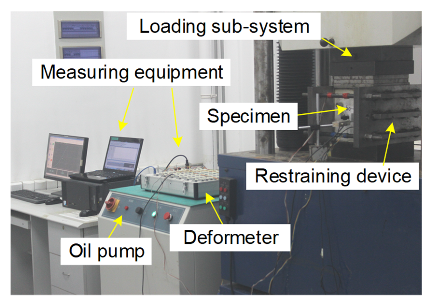
According to the mechanical model of the samples (as shown in Figure 1b), an experimental system mainly consisting of a loading sub-system, a restraint device and measuring equipment was developed, as exhibited in Figure 2. A universal servo-control testing machine (YNS-2000), with sensors to measure the sample axial force and displacement in real time during the loading process, was chosen as the loading sub-system. A constant loading rate of 0.5 mm/min was adopted and the loading direction is parallel to the weak interlayer.
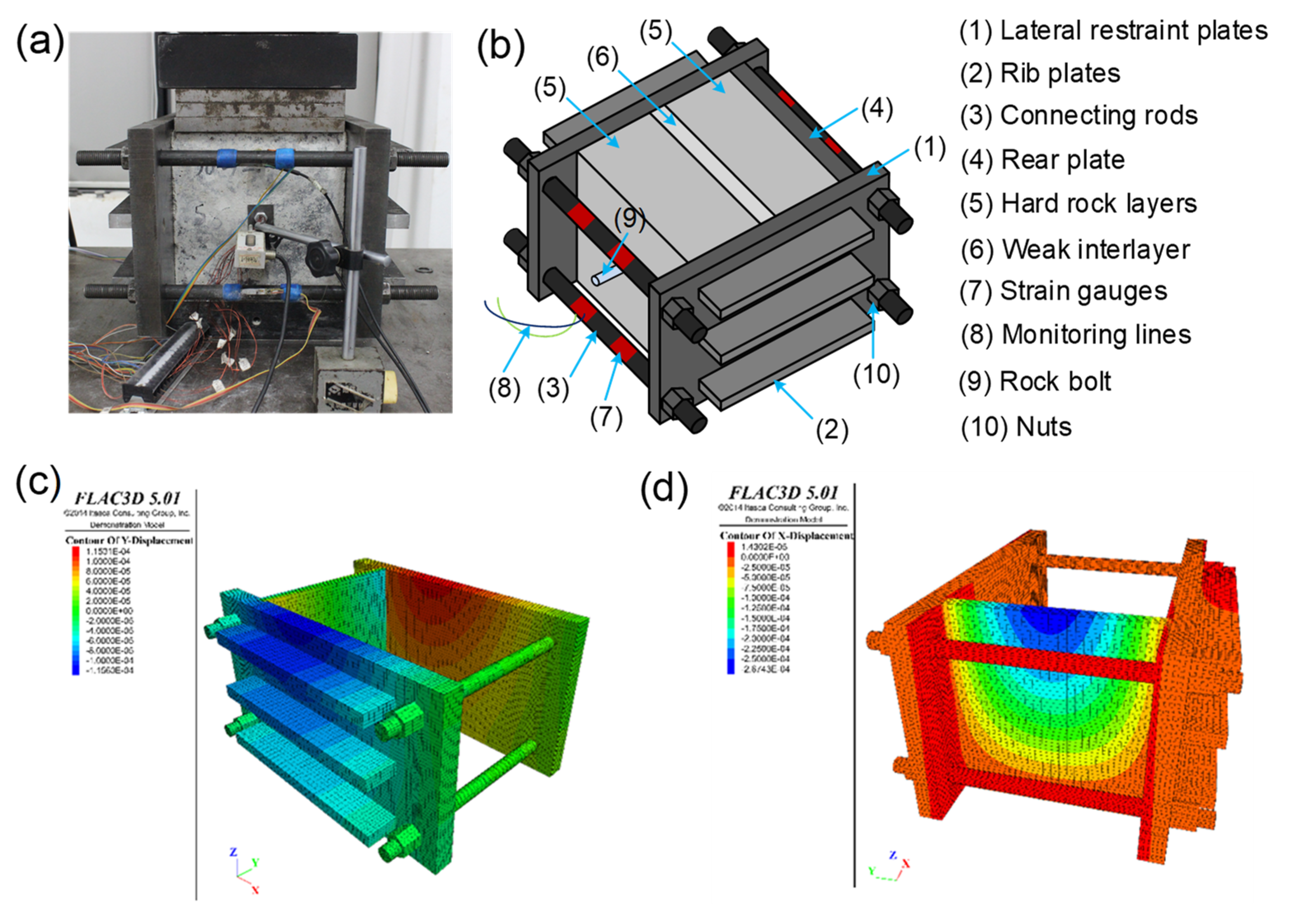
The lateral and rear restraint sub-system was self-developed and is composed of two main parts: high strength steel restraint plates and rods. The lateral restraint sub-system applies σ2 on the lateral sides of the samples and constrains the normal displacement of them. The rear restraint sub-system constrains the normal displacement of the rear side of the samples. In addition, to enhance the stiffness of the lateral restraint plates, three stiffening ribs with an interval of 56.5 mm are welded on their outer side. The setup and geometry of the self-developed system are shown in Figure 3a,b.
In order to check whether the strength and stiffness of the restraint device meet the test requirements, FlAC3D was used to check the displacement of the restraint device during the whole loading process and the calculation results are shown in Figure 3c,d. As shown in Figure 3c,d, during the compression of the specimens, the maximum deformation of the lateral and rear restraint plates is about 0.12 mm and 0.27 mm respectively, which indicates that the restraint device can meet the test requirements. In addition, there are two symmetrical platforms on each restraint rod whose size is 40 mm × 5 mm for pasting the strain gauge to monitor the lateral constraint stress σ2 during the testing. In order to eliminate the eccentric effect, two strain gauges are symmetrically pasted on the platforms of each rod.

2.3. Specimens Preparation

It should be pointed out that due to the limitation of existing technology, the artificial samples do not agree well with natural rock in many aspects. For example, the micro cracks and particle diameter of the artificial samples are hardly consistent with that of the natural rock, which influences the pressure section of the axial stress–axial strain curve. Hence, the pressure sections between the axial stress–strain curves of artificial samples and natural rock may not agree very well. Furthermore, the particle diameter of the materials may influence the mechanism of microscopic failure. Considering the difficulties of obtaining lots of rock mass with a weak interlayer, the commonly used mode materials sand, cement, gypsum, and water were chosen for samples preparation. The material for hard rock has a ratio of sand: cement: water = 4.5:1:0.55. In order to obtain weak interlayers with different strengths, the weak interlayer similar materials have the ratios of sand: cement: gypsum = 3:0.5:0.5, 4:0.6:0.4, 4:0.5:0.5, 4:0.4:0.6, 6:0.5:0.5, and 6:0.4:0.6, respectively, and the mass of water is 24% of the total mass of sand, cement, and gypsum. By using the methods aforementioned in Section 2.1, the mechanical parameters of the mode materials are obtained, as listed in Table 2. Because we paid attention to the strength, deformation, and failure mode of the samples with a weak interlayer, not on the mechanical performance of weak interlayer or hard rock layer, so the standard deviation of the normal samples used to get the parameters listed in Table 2 is not analyzed.
The samples are 200 × 200 × 200 mm3 cubes, where the weak interlayer is located in the middle of the samples and two sides are hard rock layers with equal thickness. The rock bolt traverses all three rock interlayers, as exhibited in Figure 3b. To better investigate the influence of the weak interlayer thickness, uniaxial compressive strength, and dip angle on the compression behaviors of bolted specimens with a single free surface, three cases were considered in this study.
In Case I, keeping the thickness (tw) and dip angle (αw) of the weak interlayer as 30 mm and 0°, respectively, the uniaxial compressive strength of the weak interlayer (σw) is 0.22 MPa, 0.46 MPa, 0.80 MPa, 1.27 MPa, 1.74 MPa, and 2.02 MPa, respectively, equal to about 3.05%, 6.08%, 11.10%, 24.13%, and 28.02% of the uniaxial compressive strength of hard rock, respectively. In Case II, σw and αw are fixed at 0.22 MPa and 0°, respectively, and tw varies from 0 to 30 mm at an interval of 5 mm. In Case III, tw and σw are selected at 30 mm and 0.22 MPa, and αw is 0°, 15°, 30°, 45°, and 90°, respectively, as shown in Figure 4. The details of the three cases are presented in Table 3.
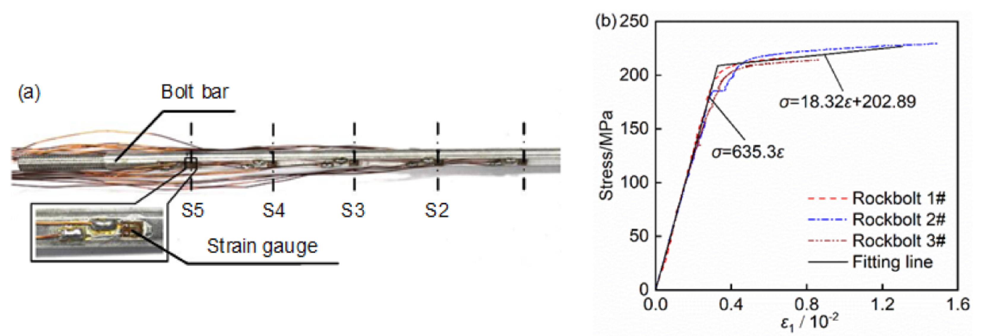
The similar material selection of the rock bolt is significant for the effects of physical simulation experiments. Combined with the bolt specifications and mechanical parameters ordinarily used in coal mines [35], the similarity ratio and the monitoring requirements of the tests, aluminum rebar with 6 mm diameter was finally selected as the rock bolt in this study, as shown in Figure 5a. In order to monitor the stress of the rock bolts during the deformation of the bolted specimens with a weak interlayer, five pairs of strain gauges are symmetrically stuck on each monitoring section. The stress–strain relationships of the rock bolts obtained by tensile tests are shown in Figure 5b.
The preparation process of the bolted weak interlayer specimens with a single free surface includes two main stages. Firstly, the unbolted specimens were made layer by layer in a self-developed steel mold at an interval of 8 h. Then they were demolded about 12 h after the final layer was cast, soaked in water for 7 days and finally cured for more than 28 days at room temperature. The second stage was the preparation of the rock bolt and its grouting, with the main steps shown as follows. Firstly, an 8 mm diameter borehole, perpendicular to the free surface of the samples, was drilled by lathe. Secondly, the grout was pressed into the borehole and stirred well. After that, the rock bolt was put into the borehole and stirred again to ensure the grout was uniform and bonded well. Finally, the bolted specimens were left at room temperature for 48 h to ensure the grout quality before testing.

3. Strength and Deformation Behavior of Bolted Specimens Containing Weak Interlay-ER

In this section, the influence of the thickness, uniaxial compressive strength, and dip angle of the weak interlayer on the strength and deformation behavior of the bolted samples having one free surface was investigated. Two indexes, Dp and DE, quantitatively describing the weakening effect of the weak interlayer on the peak strength and elastic modulus of the bolted samples, are defined by Equations (1) and (2), respectively.
D p = σ p 0 σ p w σ p 0 × 100 %
D E = E 0 E w E 0 × 100 %
where Dp, DE are the indexes of the weakening effect for the weak interlayer on the peak strength and elastic modulus of the bolted samples; σ p 0 and σ p w , E0 and Ew are the peak strength and elastic modulus of the bolted samples without and with a weak interlayer, respectively.

3.1. Typical Whole Stress–Strain Curve of Bolted Specimens

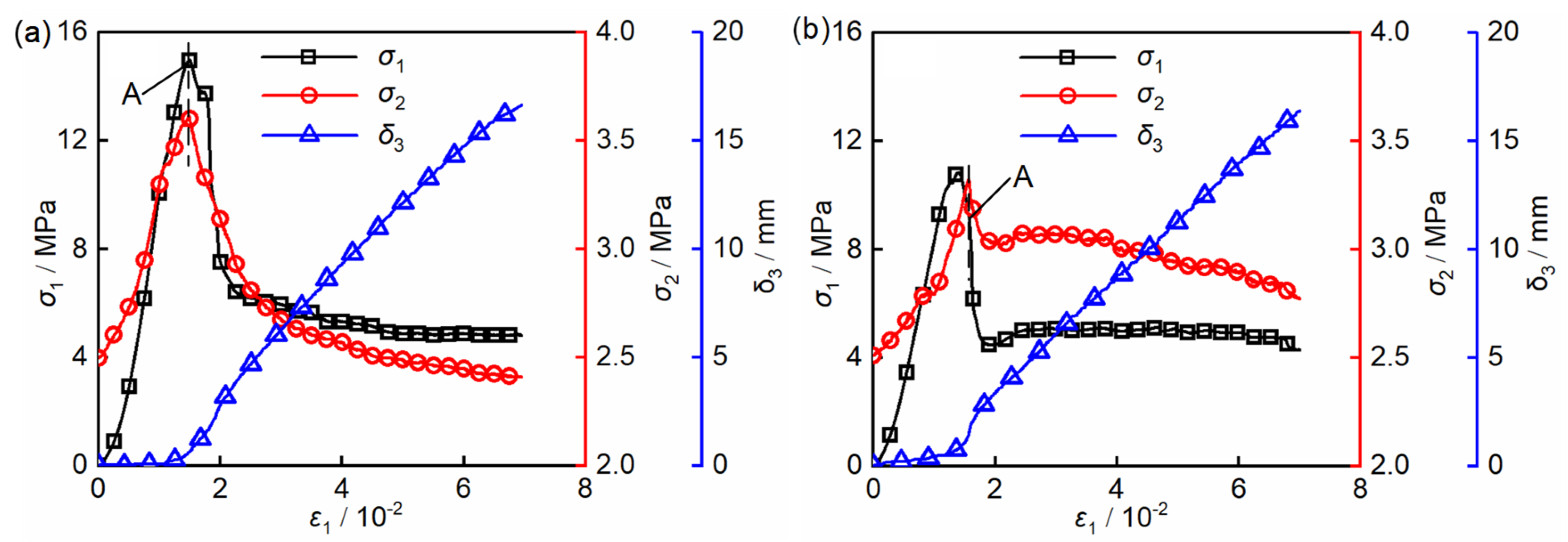
Figure 6 shows two typical whole stress–strain curves of Samples T-1 and T-6. The lateral restraint stress σ2 and normal displacement of the samples’ free surface δ3 are also clearly presented in this figure. As shown in Figure 6, the weak interlayer has no obvious influence on the deformation process of the bolted samples, because both of the samples without and with weak interlayer experience the same deformation stages, namely, the initial compressive stage, elastic stage, yielding stage, strain-softening stage, and residual strength stage. With the increasing of the axial strain of the samples ε1, the lateral constraint stress σ2 increased before points A and then decreased. Points A are located at the peak strength point (Sample T-1) or the strain-softening segment near the peak strength point (Sample T-6). Generally, the normal displacement of free surface δ3 is no more than 1 mm and exceeds 10 mm at the pre- and post-peak stage, respectively. This is because at the pre-peak stage of the bolted samples, δ3 mainly consists of elastic and plastic deformation of the samples induced by the Poisson effect; however, at the post-peak stage, δ3 is dominated by the deformation of cracks expanding and slippage of the samples.

3.2. Effect of Weak Interlayer Thickness

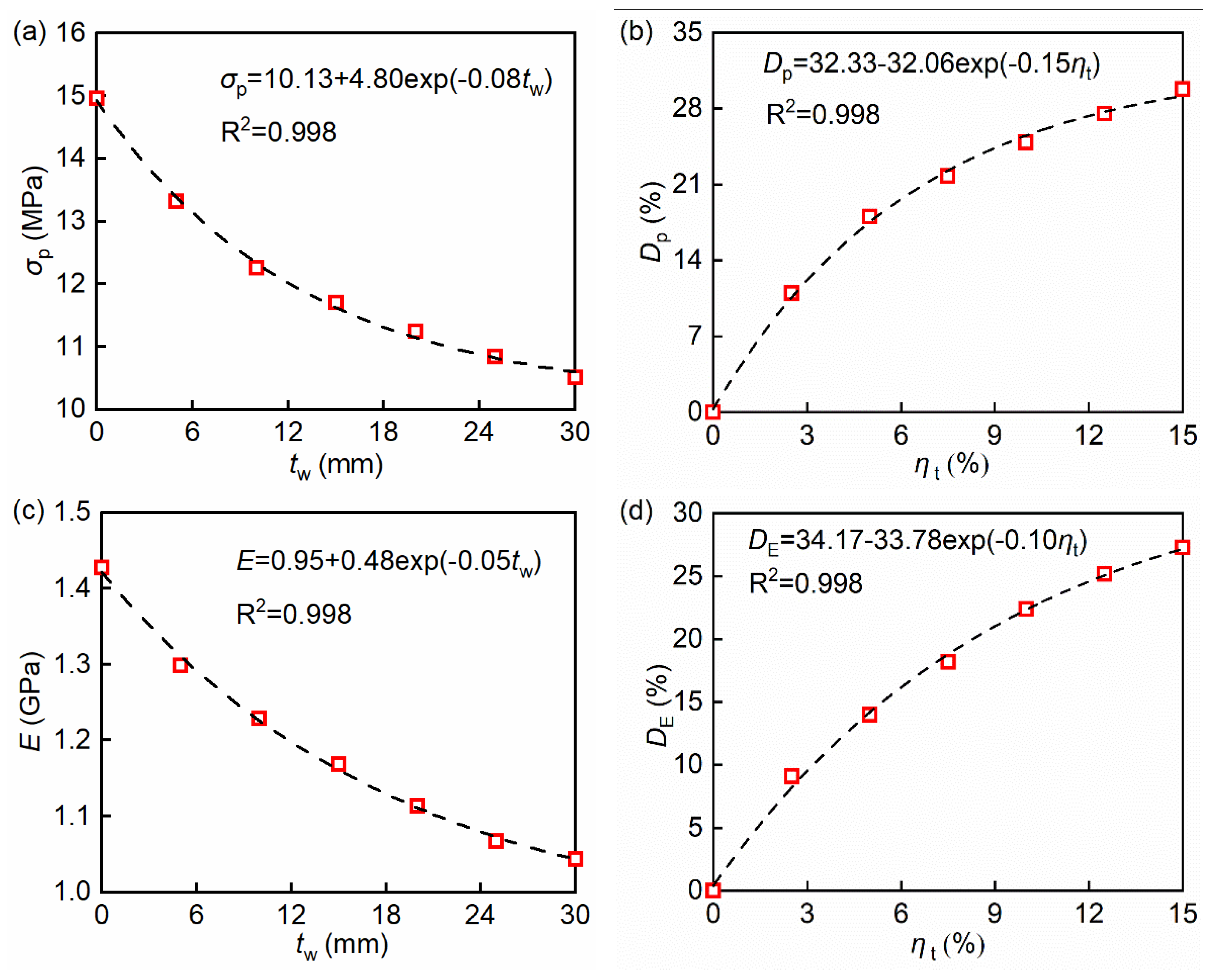
Table 4 and Figure 7 list the peak strength σp, elastic modulus E, weakening effect indexes Dp and DE when the specimens contain 0, 5, 10, 15, 20, 25, and 30 mm thick weak interlayer. As shown in Figure 7, the existence and thickness varying of the weak interlayer have a significant influence on the peak strength and elastic modulus of the samples, and the weakening effect of the weak interlayer. As the weak interlayer thickness increases from 0 to 30 mm, the peak strength and elastic modulus of the specimens exponentially decrease from 14.96 to 10.50 MPa and 1.43 to 1.04 GPa, respectively. Meanwhile, Dp and DE exponentially increase from 10.96% and 9.09% to 29.81%, and 27.27%, respectively. However, with the increasing of weak interlayer thickness, the increment rates of Dp and DE decrease. For example, when the thickness of the weak interlayer increases from 10 mm to 15 mm, the increment rates of Dp and DE are 20.72% and 29.95%, respectively, and as the thickness of the weak interlayer increases further from 25 to 30 mm, the increment rates of Dp and DE decrease to 8.24% and 8.34%, respectively.
The influence of the weak interlayer under the triaxial compressive loading obtained in this section high agrees with the previous study [36]. Nevertheless, our study investigated the specimens with a free surface compared with the research earlier, only considering the triaxial experiments, which indicates the restrain stress of the free surface applied to by the rock bolts is equal to confining pressure. In actual engineering projects, the rock bolts use to restrain stress on the free surface of the roadway or tunnel. The restrain stress makes the surrounding rock change from biaxial compression to triaxial compression. Hence, the present study is much closer to the actual projects.

3.3. Effect of the Uniaxial Compressive Strength of Weak Interlayer

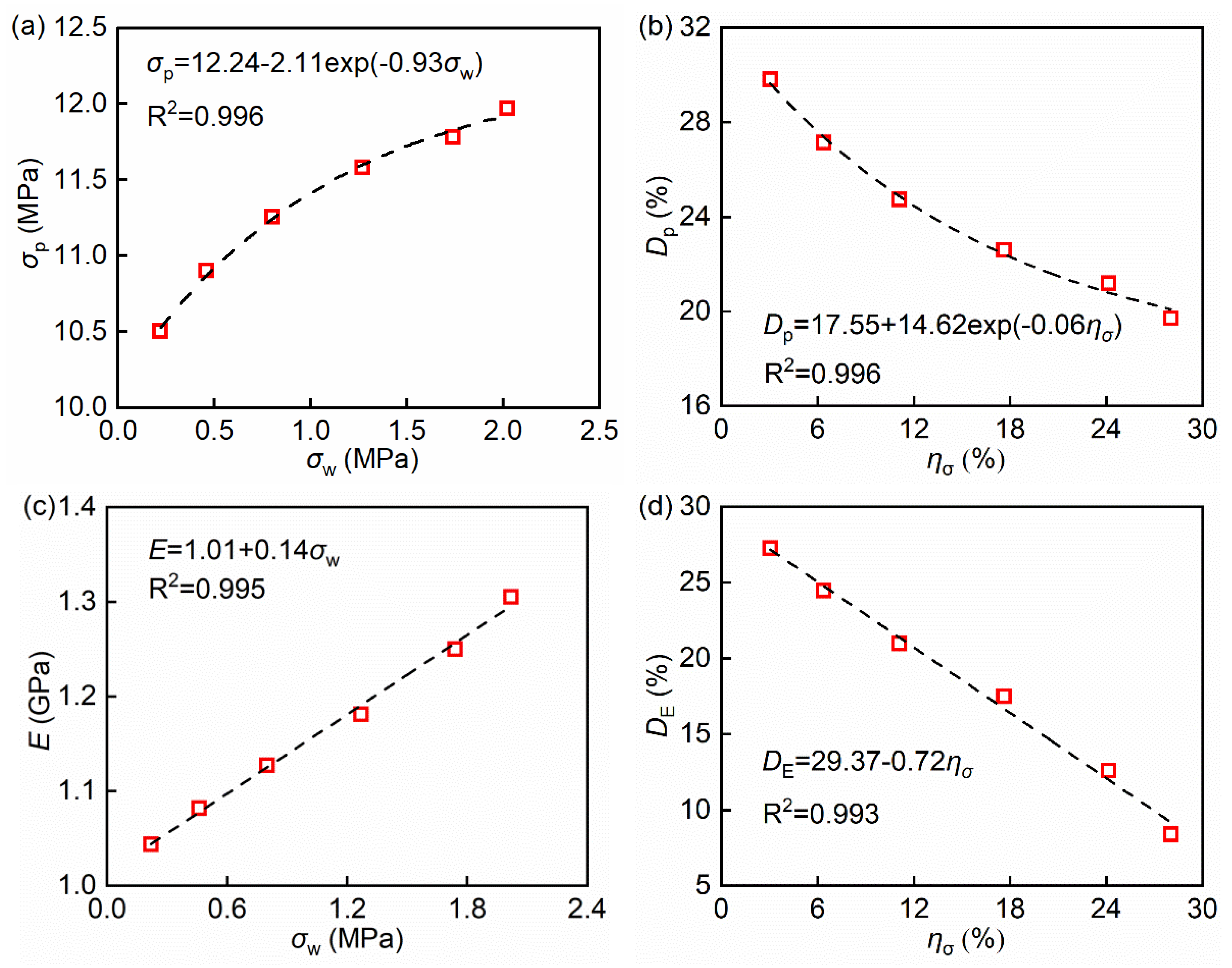
When the uniaxial compressive strength of the weak interlayer is 0.22, 0.46, 0.8, 1.27, 1.74, and 2.02 MPa, the values of σp, E, Dp, and DE are shown in Table 5 and Figure 8. From Table 5 and Figure 8, it can be seen that increase of the uniaxial compressive strength of weak interlayer has an obvious impact on the peak strength and elastic modulus of the specimens and the weakening effect of the weak interlayer. As the uniaxial compressive strength of the weak interlayer increases from 0.22 to 2.02 MPa, the peak strength of the samples exponentially increases from 10.5 to 12.01 MPa, with an incremental rate of 14.38%. Meanwhile, the elastic modulus of the samples linearly increases from 1.04 to 1.31 GPa, increasing by 25.96%. However, with increase of the uniaxial compressive strength of weak interlayer, the weakening effect of the weak interlayer on the peak strength and the elastic modulus of the samples exponentially and linearly reduces, respectively. With the uniaxial compressive strength of weak interlayer increasing from 0.22 to 2.02 MPa, Dp (Figure 7b) exponentially decreases from 29.81% to 19.72%, while DE (Figure 7d) linearly reduces from 27.27% to 8.39%.

3.4. Effect of Weak Interlayer Dip Angle

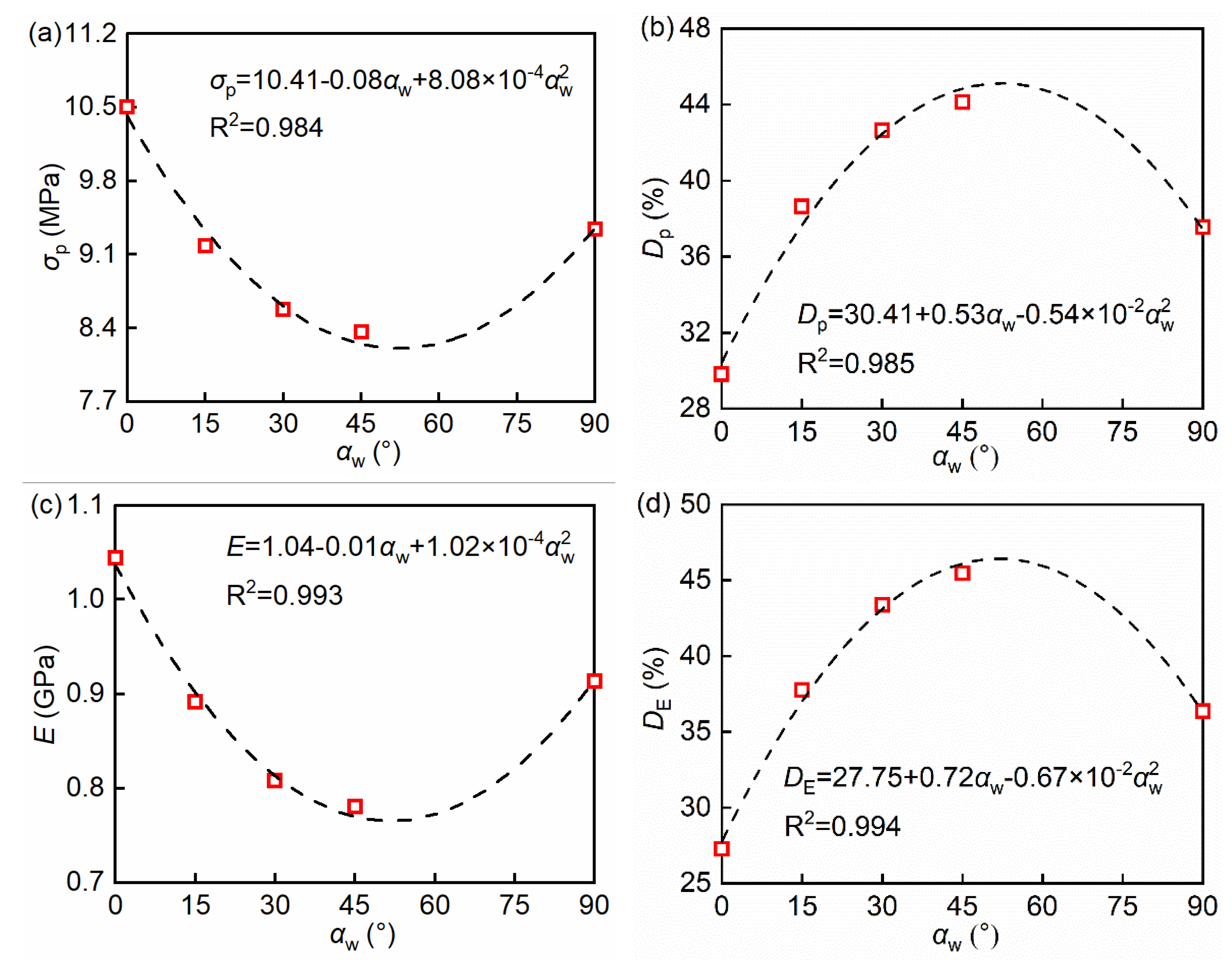
When the dip angle of the weak interlayer αw is 0°, 15°, 30°, 45°, and 90°, the peak strength σp and the elastic modulus E of the samples, and the weakening effect indexes Dp and DE are displayed in Table 6 and Figure 9. It shows that the variation of the weak interlayer dip angle has a remarkable influence on the peak strength σp and elastic modulus E of the specimens and the weakening effect of the weak interlayer. As αw varies from 0 to 90°, both σp and E change following the parabolic law. In particular, they decrease as αw increases from 0° to 45° and then increase as αw increases from 45 to 90°. What is more, as αw grows from 0 to 90°, the variation of the weakening effect indexes Dp and DE is similar to that of σp and E. In addition, when αw equals to 45°, the weak interlayer has the strongest weakening effect, because both Dp and DE reach their maximum value when αw equals to 45°.

3.5. Mechanism of Weakening Effect of Weak Interlayer

According to Section 3.1, Section 3.2 and Section 3.3, it is clear that the weak interlayer has an obvious weakening effect on the peak strength and elastic modulus of the samples. In this subsection, the mechanism of the weakening effect of the weak interlayer would be discussed.
With increase of the weak interlayer thickness, although its bearing capacity Fw increases, the bearing capacity Fh of the hard rock decreases because its thickness is decreasing (the total thickness of the weak interlayer and hard rock layers is constant). What is more, the reduction magnitude of the hard rock’s bearing capacity ΔFh is bigger than the increasing value of the bearing capacity of the weak interlayer ΔFw. So, the specimens’ bearing capacity Fa decreases with the increasing weak interlayer thickness. When the weak interlayer thickness tw and dip angle αw are constant, Fh is constant, but Fw increases with increase of the uniaxial compressive strength of the weak interlayer. As a consequence, Fa increases as the uniaxial compressive strength of the weak interlayer increases. When the weak interlayer thickness tw and the uniaxial compressive strength σw are constant, the weak interlayer across the sectional area Sw increases when αw increases from 0 to 45° and decreases as αw increases from 45 to 90°. So, Fa first increases and then decreases as αw increases from 0 to 90°.
The weakening effect of the weak interlayer on the elastic modulus of specimens is related to the lower elastic modulus of the weak interlayer. Under the same axial load, the samples containing a weak interlayer will deform more than those without it. Therefore, the elastic modulus of the specimens with a weak interlayer will be lower than that without it. This, to some extent, explains the weakening effect mechanism of the weak interlayer on the peak strength and elastic modulus of the samples.
It is well known that the reinforcement effect was influenced by the properties of rock mass and boundary conditions, etc. Therefore, in order to make our research more universal and provide guidance for more engineering situations, we have studied as many variables of the weak interlayer as possible, including strength, thickness and angle. However, it should be pointed out that the actual situation in underground engineering is very complicated. Therefore, the applicability of the research results to other rock mass conditions should be examined, in particular, the non-coal hard rock mining.

4. Influence of Weak Interlayer on the Failure Modes of the Bolted Samples

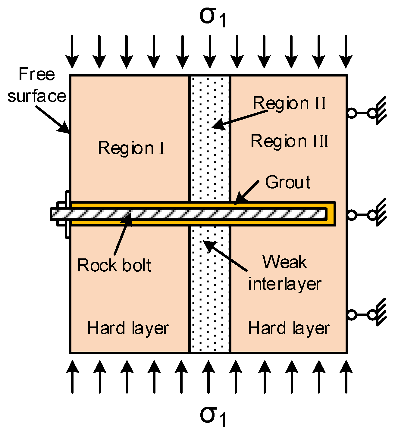
The failure mode is one very important basis for the stability control of underground engineering, such as roadways and mining projects [37]. In this section, the influence of the thickness, the uniaxial compressive strength and dip angle of the weak interlayer on the fracture distribution and failure mode of the samples is systematically analyzed. To facilitate analysis, the area between the sample’s free surface and the weak interlayer is defined as region I, the location of the weak interlayer is regarded as region II, and the zone between the weak interlayer and the rear side of the sample is treated as region III, as exhibited in Figure 10. In addition, the cracks are classified as controlling cracks and non-controlling cracks according to their characteristics. The cracks determining the failure mode of the specimen are defined as controlling cracks, while the others are named as non-controlling cracks.

4.1. Analysis of the Effect of Weak Interlayer Thickness

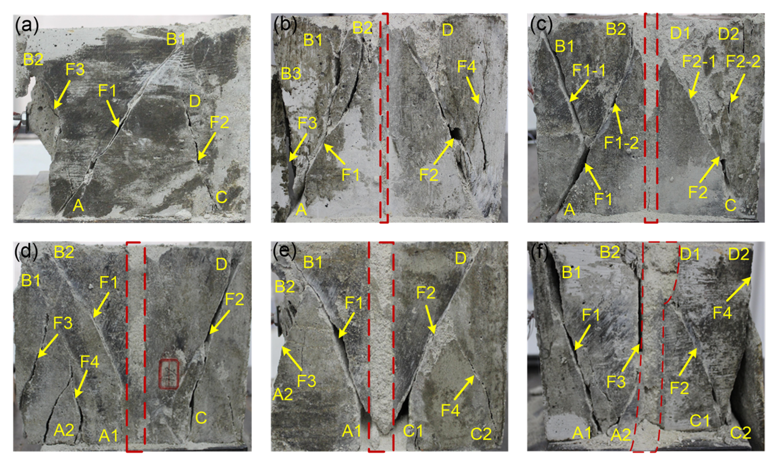
Figure 11 presents the ultimate failure modes of the samples without and with different thickness weak interlayers. The thickness of the weak interlayer has little influence on the failure modes of the specimens, but has a noticeable impact on the distributions of the cracks. ① When there is no weak interlayer (Sample T-1), the single controlling crack F1 extends from point A to point B1, running through regions I, II, and III of the sample diagonally. The controlling crack F1 fails due to a compressive-shear mechanism because of friction marks occurring in its failure surface. The non-controlling cracks F2 and F3 are distributed in regions I and III, but neither of them extends throughout the sample, as shown in Figure 11a. ② However, for the samples containing weak interlayers with the thickness of 5, 10, 15, and 20 mm (Samples T-2~T-5), there are usually two controlling cracks F1 and F2 subjected to a compressive-shear mechanism. Normally, the two controlling cracks are located in the hard rock layers, i.e., regions I and III, and extend from the points near the weak interlayer to the points far from the weak interlayer. In addition, several non-controlling cracks occur in each of these samples, but most of them do not run through the samples. ③ When tw = 25 mm, three controlling cracks F1, F2 and F3 occur in the sample; F1 and F3 fail due to a tensile mechanism, while F2 fails due to a compressive-shear mechanism. F1 and F2 are distributed in regions I and III, respectively, while most of the section of F3 is along the interface of regions I and II. ④ When the samples contain a weak interlayer, no macro cracks occur in the weak interlayers, but the weak interlayers become thicker after testing than before. The reasons for this may be as follows:
Firstly, under the test conditions of this paper, the weak interlayer, restrained all around by hard rock layers, the lateral restraint plates and loading plates of the testing machine, is recompressed together after destruction because it is crushed into powder and so becomes thicker after testing.
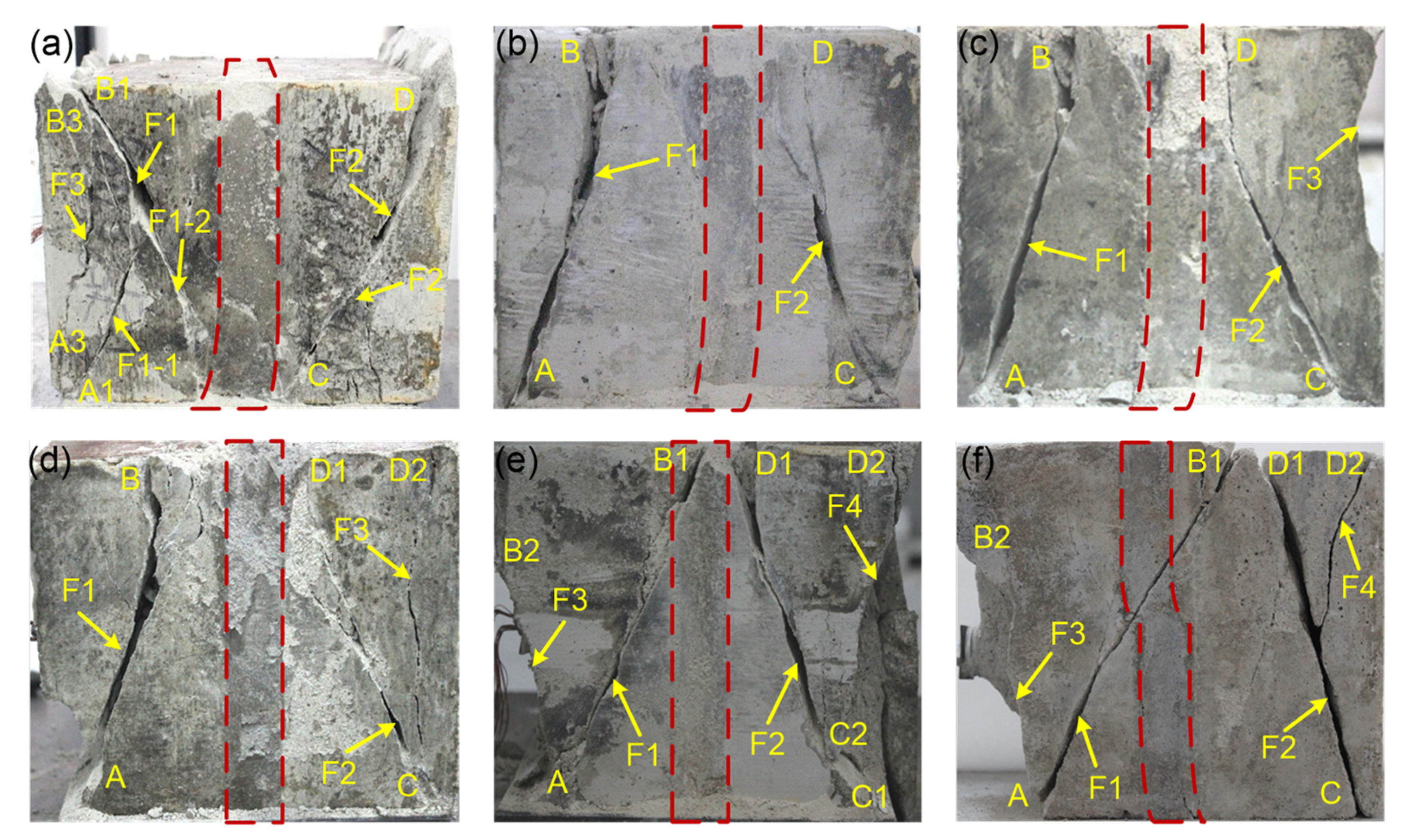
Secondly, in the loading process, the weak interlayer yields first due to its lower strength and then unload after yielding. However, after the yielding of weak interlayer, the hard rock layers keep bearing new incremental load and will fracture when their bearing load reaches a certain value. So, the macro cracks occur in hard rock layers rather than in the weak interlayer. However, if the weak interlayer has a free surface or its uniaxial compressive strength is more than 1.74 MPa, a macro crack will be observed in the weak interlayer, as shown in Figure 11f and Figure 12d.
In addition, as shown in Figure 11, two different failure modes, which are (a) Type-I, the compressive-shear failure mode and (b) Type-II, the shear and tensile failure mode, are observed according to the failure mechanism of the controlling cracks. The failure mode of the sample is defined as Type-I if its controlling cracks fail due to a compressive-shear mechanism. If the controlling cracks of the sample are subjected to a compressive-shear mechanism and tensile mechanism, this failure mode is defined as Type-II. Accordingly, it is clear that samples T-1 (without weak interlayer) to T-5 are subjected to the compressive-shear failure mode (Type-I), and sample T-6 fails to the shear and tensile failure mode (Type-II).

4.2. Analysis of the Effect of the Uniaxial Compressive Strength of Weak Interlayer

The failure modes and cracks distribution of the samples influenced by the uniaxial compressive strength of weak interlayer, which increases from 0.22 to 2.02 MPa, are shown in Figure 12. Similar to the influence of the thickness, the variation has a great and a rare influence on the distribution of cracks and the failure mode of the specimens, respectively. When σw is lower, e.g., σw ≤ 1.27 MPa (Samples S-1 to S-4), the number, distribution and failure mechanism of the controlling cracks F1 and F2 are similar to those of samples T-2~T-5. As σw increases to 1.74 MPa, the controlling crack F1 extends from point A to B1, enters into the weak interlayer and fails due to a compressive-shear mechanism; another controlling crack F2, subjected to a compressive-shear mechanism is located in region III and extends from point C1 to point D1. What is more, with σw further increasing to 2.02 MPa, the single controlling crack F1 (Figure 12f) is oblique throughout the three regions of the samples, fails due to a compressive-shear mechanism and extends from point A to point B1. By comparison of Figure 11f with Figure 10, it can be seen that the orientations of crack F1 of the two samples are very similar. As σw ≥ 1.74 MPa, the weak interlayer can bear more load and will not be recompressed together after destruction because it breaks into small blocks. So, macro cracks are observed in the weak interlayer as σw ≥ 1.74 MPa. As for the failure mode, it is clear that all of the specimens containing a weak interlayer with different uniaxial compressive strength fail due to the compressive-shear failure mode (Type-I).
Additionally, according to the distributions of cracks occurring in the samples containing a weak interlayer with different uniaxial compressive strength, it is apparent that there is a synergistic bearing effect between the hard rock and weak interlayer and this will be discussed in Section 4.4.

4.3. Analysis of the Effect of Weak Interlayer Dip Angle

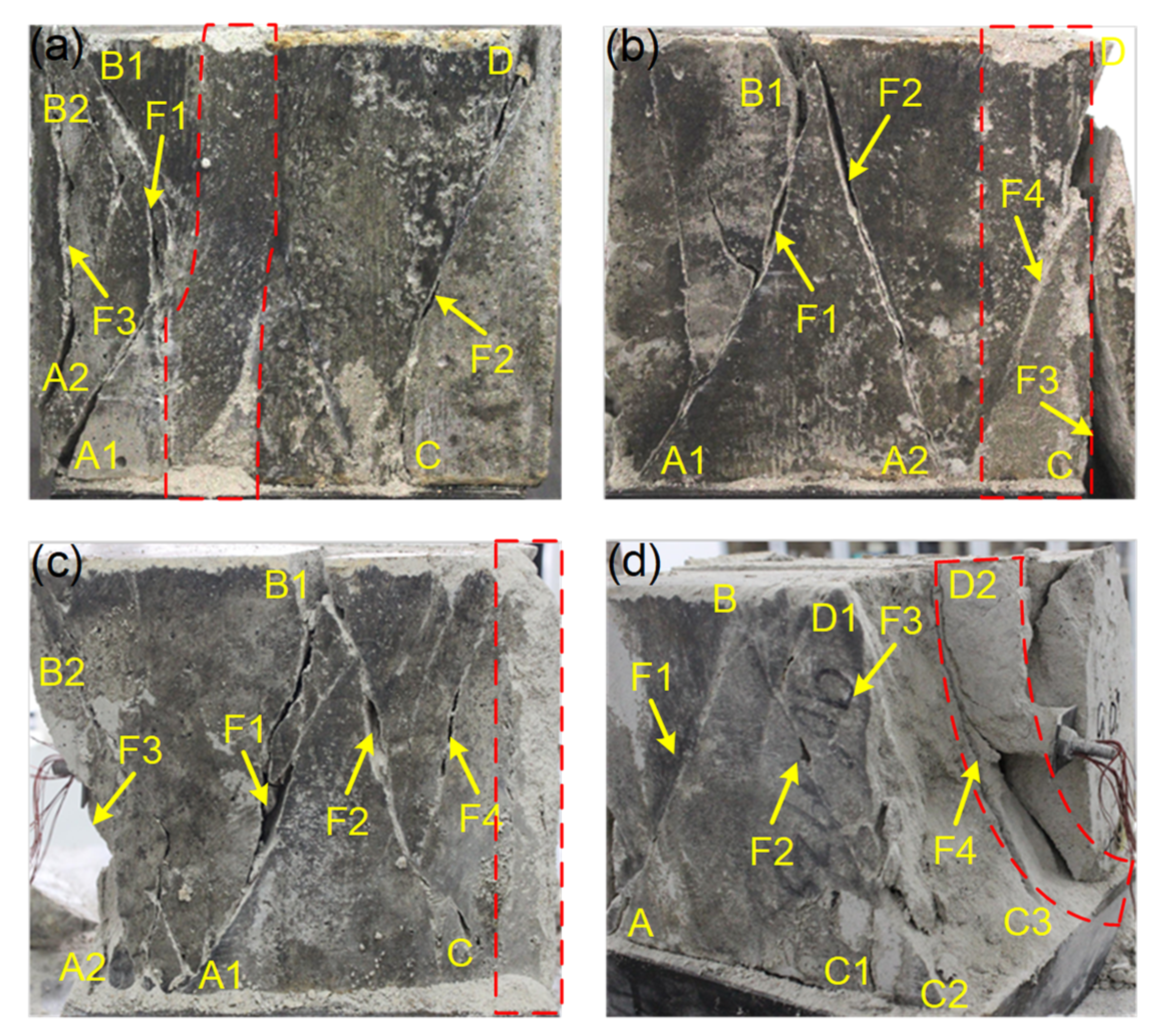
The crack distribution and failure mode of the samples containing weak interlayer with a dip angle of 15°, 30°, 45°, and 90° are shown in Figure 13 (for α = 0°, the crack distribution and failure mode of the specimen are listed in Figure 13a). The dip angle of the weak interlayer has an obvious influence on the cracks distribution of the specimens. To be specific, when α = 15°, the controlling cracks F1 and F2 are located in regions I and III, respectively. In addition, there are several non-controlling cracks in the site between F1 and the free surface of the specimen. When α = 30°, the controlling cracks F1 and F2 are situated in region I and coalesce with each other at point B1 located at the upper end of the sample. The non-controlling crack F3 occurs in region III and leads to the spalling of the rear part. In addition, it is noteworthy that there is a non-controlling crack F4 obliquely across the weak interlayer. With the dip angle increasing, one end of the weak interlayer is close to the free surface of the sample, while the other end is close to the rear side of the specimen, as shown in Figure 4. Therefore, once the crack is near the rear end of the sample, the weak interlayer will be cut by the crack. In the case of α = 45°, the distribution and orientation of controlling cracks F1 and F2 are similar to those in the case of α = 30°.
At α = 90°, the cracks are situated not only in the hard rock layers but also in the weak interlayer. What is more, some blocks near the free surface fall out. In the case of α = 90°, the fractured weak interlayer near the free surface will be squeezed out of the sample rather than be recompressed together due to the influence of its free surface. In addition, with the destruction of the weak interlayer, the interlocking effect of the layers fades away and the supporting effect of the rock bolt on the hard rock is gradually lost. This, to some extent, explains the failure pattern of the sample when α = 90°.
In addition, samples A-2 (α = 15°), A-3 (α = 30°), and A-4 (α = 45°) are subjected to the compressive-shear failure mode (Type-I) because their controlling cracks fail due to a compressive-shear failure mechanism, while sample A-5 (α=90°) fails in shear and tensile failure mode (Type-II) because its controlling cracks F1~F3 are subjected to a compressive-shear failure mechanism, but controlling crack F4 fails due to a tensile failure mechanism.

4.4. Analysis on the Synergistic Bearing Effect between Hard Rock and Weak Interlayer

In this paper, the axial displacement and strains of the weak interlayer and hard rock are compatible, or the same during the compression deformation process due to the loading was controlled by displacement and the weak interlayer was restrained by hard rock layers and lateral restraint plates. Hence, the weak interlayer and hard rock layers have the same strain during the elastic deformation stage of the samples. The synergistic bearing effect between the hard rock and weak interlayer is observed, which can be analyzed through the failure mode of the samples as shown in Figure 11. When the uniaxial compressive strength of the weak interlayer is no more than 1.27 MPa (about 17.61% of the hard rock’s uniaxial compressive strength), the synergistic bearing effect between the hard rock and weak interlayer is weak and the cracks are mainly located in the hard rock layers. As the uniaxial compressive strength of the weak interlayer reaches 1.74 MPa (about 24.13% of the hard rock’s uniaxial compressive strength), the synergistic bearing effect of the weak interlayer and hard rock layers is moderate and the crack invades but does not run through the weak interlayer. However, when the uniaxial compressive strength of weak interlayer reaches 2.02 MPa, the synergistic bearing effect between the hard rock and weak interlayer is strong and the controlling crack F1 runs through the weak interlayer, as shown in Figure 11f. According to the present research results, the strength of weak interlayer is the main factor influencing the synergistic bearing effect between the hard rock and weak interlayer. With increase of the uniaxial compressive strength of weak interlayer, its bearing capacity increases; on the other hand, the interaction between the hard rock and weak interlayer is enhanced. Hence, the synergistic bearing effect between the hard rock and weak interlayer increases with increase of the uniaxial compressive strength of weak interlayer.

5. Analysis on Bolt Performance during the Deformation Process of the Specimens

The bolt force dominated by axial force and bending moment provides a basis to better understand the performance, to precisely evaluate the reinforcing effect and to optimize the design of the bolt [38,39]. Under working conditions, the bolt force (except for the pretension force) is induced by the deformation of the rock mass [40,41]. Therefore, it is of great importance to investigate the bolt force during the deformation process of the bolted samples. In this section, Samples T-1 and T-6 are picked as two representative specimens to analyze the evolution of the bolt axial force and bending moment during the deformation of the bolted specimens containing a weak interlayer.

5.1. Evolution of Bolt Axial Force

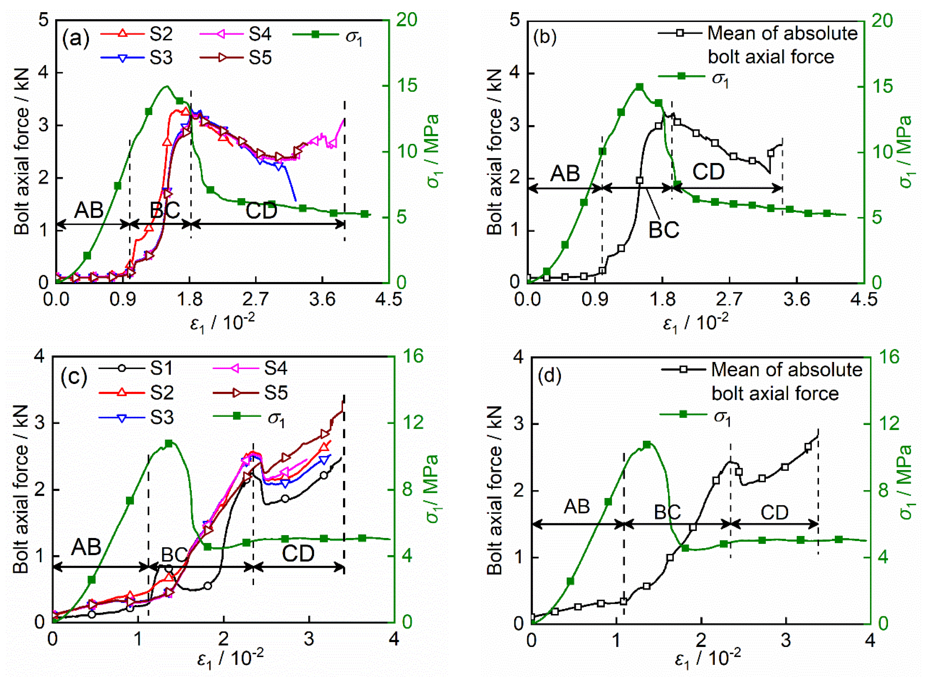
The evolution of the bolt axial force during the deformation process of the samples is shown in Figure 14. As can be seen, the evolution of the bolt axial force is closely related to the deformation of the rock mass and is characterized in stages. Taking Figure 14b as an example, at the initial compressive and elastic deformation stage of the sample (segment AB), the bolt axial force changes slowly, and this stage is named stage I: slowly-changing stage. As the sample yields and enters the strain-softening stage (segment BC), the bolt axial force increases sharply and enters stage II, fast-changing stage. However, at the strain-softening stage and residual stage of the specimen (segment CD), the bolt axial force experiences a moderately fast downturn stage, namely, stage III: less fast-changing stage.
At the initial compressive and elastic deformation stage of the sample, the normal displacement of the specimen’s free surface δ3 is induced by the Poisson effect and changes slowly. As a result, the bolt axial force changes slowly. However, after yielding of the sample, δ3 is gradually dominated by the opening and slippage of cracks and increases fast, so the bolt axial force increases sharply. However, at stage III, lots of cracks occur in the specimen and grout, and these induce the bonding action between the bolt–grout and grout–borehole interface. Once the bonding action is less than the bolt axial force, the latter will decrease with increasing deformation of the sample, and vice versa. This can explain the phenomenon that at stage III the bolt axial force of Sample T-1 (Figure 14a,b) decreases, while that of Sample T-6 (Figure 14c,d) increases.
The evolution laws of bolt axial force in this study are highly consistent with the previous research [24]. The difference is that in the previous study [24], the evolution of bolt axial force was divided into four stages, which indicate that the evolutions of bolt axial force is complicated during the deformation of the rock or rock mass. Here, we further consider that the specific evolution stages may be influenced by these factors, such as the types and deformation rate of rock masses.

5.2. Evolution of Bolt Bending Moment

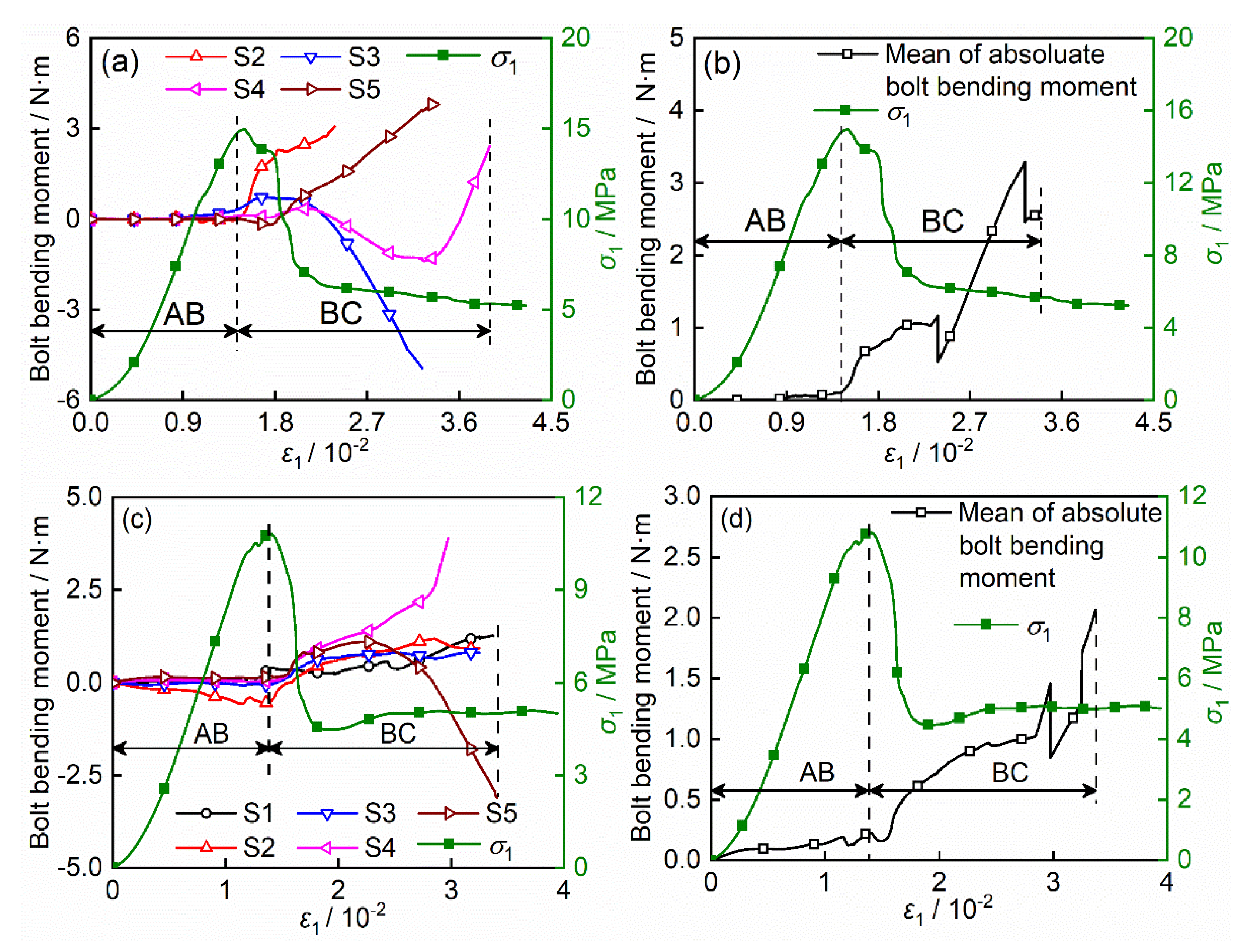
Rock bolts are usually subjected to shear and bending moment in the field [2,42]. Figure 15 shows the evolution of the bolt bending moment during the deformation process of the samples. Similar to the evolution of the bolt axial force, the evolution of the bolt bending moment is greatly impacted by the deformation of the specimens and has obvious phase characteristics, but the evolution of the bolt bending moment can only be divided into slowly-changing stage and fast-changing stage, which are corresponds to the pre- and post-peak stage of the samples, respectively.
The bolt is subjected to bending moment when the distribution of the sample’s axial displacement is non-uniform and nonlinear along the bolt axis. At the pre-peak stage, the distribution of the specimen’s axial displacement is small and very uniform because it mainly consists of elastic and plastic deformation. However, at the post-peak stage, the distribution of the sample’s axial displacement gradually becomes more non-uniform and nonlinear due to the opening and slippage of the cracks. This can explain the evolution features of the bolt bending moment during the deformation process of the samples.
It is should be pointed out that the plus or minus sign of the bending moment just indicates that the bolt bending directions are different. Figure 15 also denotes that the different sections of the bolt may have different bending directions and even that the same section of the bolt may vary in its bending direction during the specimen deformation process.

6. Conclusions

In this paper, self-prepared samples containing weak interlayers and rock bolts capable of monitoring their axial force and bending moment were used to experimentally investigate the influence of the thickness, uniaxial compressive strength, and dip angle of weak interlayer on the compressive behavior of the bolted samples with a single free surface on the basis of a set of self-developed tests. According to the research results, the following conclusions were obtained.
(1) The thickness, uniaxial compressive strength and dip angle of the weak interlayer have a significant weakening effect on the peak strength and elastic modulus of the samples with a single free surface. With the increase of the weak interlayer thickness, the peak strength and elastic modulus of the samples exponentially decrease. The descending speed is relatively fast at the beginning, as the thickness of the weak interlayer increases, the intensity attenuation gradually slows down. By contrast, the peak strength and elastic modulus of the samples would increase exponentially and linearly with the increment of the uniaxial compressive strength of the weak interlayer. Nevertheless, as the dip angle of the weak interlayer varies from 0 to 90°, the peak strength and elastic modulus of the samples present a different trend. They firstly increased and then decreased due to the weakening effect of the weak interlayer.
(2) The weak interlayer also greatly affects the crack distribution and failure mode of the samples. Two failure modes, namely compressive-shear failure mode and tensile-shear failure mode, are observed with the destruction of the sample. The thickness and uniaxial compressive strength of the weak interlayer have little influence on the failure modes of the specimens, but own a noticeable impact on the distributions of the cracks. As the thickness of the weak interlayer increases, the number of cracks becomes more and the distribution becomes more uneven. Similarly, the decrease in the strength of the weak interlayer would also cause the increment and uneven distribution of cracks during the destruction of the specimen. In contrast, the failure modes resulting from the change of the weak interlayer dip angle are different. When the dip angle is low, the cracks develop separately in the hard rock layer. As the angle of the weak interlayer becomes larger, the cracks in the two hard layers develop into the weak interlayer and finally form a penetration.
(3) The synergistic bearing effect between the hard rock layers and weak interlayer is much stronger under higher strength, thicker thickness and smaller dip angle of the weak interlayer. When the strength of the weak interlayer is lower than 1.27 MPa, the thickness exceeds 20 mm, and the dip angle exceeds 15°, the synergistic bearing effect will be significantly reduced. The evolution of the bolt force and bending moment are greatly impacted by the deformation process of the samples. During this deformation process, the bolt force shows three evolution stages, i.e., a slowly-changing stage (stage I), fast-changing stage (stage II), and moderately-changing stage (stage III). While the bolt bending moment only has two evolution stages, namely, a slowly-changing stage and a fast-changing stage, which correspond to the pre-and post-peak stages of the samples, respectively. Hence, in actual mining engineering, the stability of the surrounding rock of the mine can be judged by detecting the failure stage of the bolt.
In this study, the experimental methods are used to investigated the influence of uniaxial compressive strength, thickness and angle of WI on the reinforcement effect of the bolted rock mass with a WI. There is no doubt that numerical studying is significant in investigating the stability of the underground engineering [43,44]. In our subsequent work, we will consider the use of numerical simulation methods to study better the impact of weak interlayers, especially research on nonlinear soft interlayers that are difficult to conduct in experiments.

Author Contributions

S.D., Y.G. and H.J. conceived and designed the experiments; S.D., Y.G., X.S. and Y.Q. performed the experiments; S.D. and J.G. analyzed the data. All authors have read and agreed to the published version of the manuscript.

Funding

This study was supported by the National Natural Science Foundation of China (No. 51734009, 52074259) and Doctor Foundation of Henan Polytechnic University (B2019-35) and China Scholarship Council.

Institutional Review Board Statement

Not applicable.

Informed Consent Statement

Not applicable.

Data Availability Statement

No new data were created or analyzed in this study. Data sharing is not applicable to this article.

Conflicts of Interest

The authors declare no conflict of interest.

References

  1. Liu, C.; Li, Y. Analytical study of the mechanical behavior of fully grouted bolts in bedding rock slopes. Rock Mech. Rock Eng. 2017, 50, 2413–2423. [Google Scholar] [CrossRef]
  2. Kang, H.; Wu, Y.; Gao, F.; Jiang, P.; Cheng, P.; Meng, X.; Li, Z. Mechanical performances and stress states of rock bolts under varying loading conditions. Tunn. Undergr. Space Technol. 2016, 52, 138–146. [Google Scholar] [CrossRef]
  3. Ning, J.; Wang, J.; Bu, T.; Hu, S.; Liu, X. An innovative support structure for gob-side entry retention in steep coal seam mining. Minerals 2017, 7, 75. [Google Scholar] [CrossRef] [Green Version]
  4. Yang, H.; Cao, S.; Li, Y.; Sun, C.; Guo, P. Soft roof failure mechanism and supporting method for gob-side entry retaining. Minerals 2015, 5, 707–722. [Google Scholar] [CrossRef] [Green Version]
  5. Wang, J.; Qiu, P.; Ning, J.; Zhuang, L.; Yang, S. A numerical study of the mining-induced energy redistribution in a coal seam adjacent to an extracted coal panel during longwall face mining: A case study. Energy Sci. Eng. 2020, 8, 817–835. [Google Scholar] [CrossRef] [Green Version]
  6. Peng, S.S.; Tang, D. Roof bolting in underground mining: A state-of-the-art review. Int. J. Min. Eng. 1984, 2, 1–42. [Google Scholar] [CrossRef]
  7. Song, G.; Li, W.; Wang, B.; Ho, S.C.M. A review of rock bolt monitoring using smart sensors. Sensors 2017, 17, 776. [Google Scholar] [CrossRef] [Green Version]
  8. Li, W.; Li, S.; Feng, X.; Li, S.; Yuan, C. Study of post-peak strain softening mechanical properties of rock based on Mohr-Coulomb criterion. Chin. J. Rock Mech. Eng. 2011, 7, 1460–1466. [Google Scholar]
  9. Bjurstrom, S. Shear strength of hard rock joints reinforced by grouted untensioned bolts. In Proceedings of the Third Congress of the International Society for Rock Mechanics, Denver, CO, USA, 1–7 September 1974; Volume 2, pp. 1194–1199. [Google Scholar]
  10. Wu, X.; Jiang, Y.; Li, B. Influence of joint roughness on the shear behaviour of fully encapsulated rock bolt. Rock Mech. Rock Eng. 2018, 51, 953–959. [Google Scholar] [CrossRef]
  11. Chen, N.; Zhang, X.; Jiang, Q.; Feng, X.; Wei, W.; Yi, B. Shear behavior of rough rock joints reinforced by bolts. Int. J. Geomech. 2018, 18, 04017130. [Google Scholar] [CrossRef]
  12. Grasselli, G. 3D behaviour of bolted rock joints: Experimental and numerical study. Int. J. Rock Mech. Min. Sci. 2005, 42, 13–24. [Google Scholar] [CrossRef]
  13. Jalalifar, H.; Aziz, N.; Hadi, M. The effect of surface profile, rock strength and pretension load on bending behaviour of fully grouted bolts. Geotech. Geol. Eng. 2006, 24, 1203–1227. [Google Scholar] [CrossRef]
  14. Jalalifar, H.; Aziz, N. Experimental and 3D numerical simulation of reinforced shear joints. Rock Mech. Rock Eng. 2010, 43, 95–103. [Google Scholar]
  15. Li, L.; Hagan, P.; Saydam, S.; Hebblewhite, B.; Li, Y. Parametric study of rockbolt shear behaviour by double shear test. Rock Mech. Rock Eng. 2016, 49, 4787–4797. [Google Scholar]
  16. Li, X.; Aziz, N.; Mirzaghorbanali, A.; Nemcik, J. Behavior of fiber glass bolts, rock bolts and cable bolts in shear. Rock Mech. Rock Eng. 2016, 49, 2723–2735. [Google Scholar] [CrossRef]
  17. Shi, X.; Jing, H.; Zhao, Z.; Gao, Y.; Zhang, Y.; Bu, R. Physical Experiment and Numerical Modeling on the Failure Mechanism of Gob-Side Entry Driven in Thick Coal Seam. Energies 2020, 13, 5425. [Google Scholar] [CrossRef]
  18. Yang, X.-X.; Qiao, W.-G. Numerical investigation of the shear behavior of granite materials containing discontinuous joints by utilizing the flat-joint model. Comput. Geotech. 2018, 104, 69–80. [Google Scholar] [CrossRef]
  19. Narr, W.; Suppe, J. Joint spacing in sedimentary rocks. J. Struct. Geol. 1991, 13, 1037–1048. [Google Scholar]
  20. Li, Y.; Liu, W.; Yang, C.; Daemen, J.J. Experimental investigation of mechanical behavior of bedded rock salt containing inclined interlayer. Int. J. Rock Mech. Min. Sci. 2014, 69, 39–49. [Google Scholar]
  21. Jing, H.-W.; Yang, S.-Q.; Zhang, M.-L.; Xu, G.; Chen, K. An experimental study on anchorage strength and deformation behavior of large-scale jointed rock mass. Tunn. Undergr. Space Technol. 2014, 43, 184–197. [Google Scholar]
  22. Srivastava, L.P.; Singh, M. Effect of fully grouted passive bolts on joint shear strength parameters in a blocky mass. Rock Mech. Rock Eng. 2015, 48, 1197–1206. [Google Scholar] [CrossRef]
  23. Zhang, B.; Li, S.; Xia, K.; Yang, X.; Zhang, D.; Wang, S.; Zhu, J. Reinforcement of rock mass with cross-flaws using rock bolt. Tunn. Undergr. Space Technol. 2016, 51, 346–353. [Google Scholar] [CrossRef]
  24. Su, H.; Jing, H.; Zhao, H.; Yu, L.; Wang, Y. Strength degradation and anchoring behavior of rock mass in the fault fracture zone. Environ. Earth Sci. 2017, 76, 179. [Google Scholar] [CrossRef]
  25. Zhu, W.; Jing, H.; Yang, L.; Pan, B.; Su, H. Strength and deformation behaviors of bedded rock mass under bolt reinforcement. Int. J. Min. Sci. Technol. 2018, 28, 593–599. [Google Scholar] [CrossRef]
  26. Teng, J.; Tang, J.; Zhang, Y.; Li, X. CT experimental study on the damage characteristics of anchored layered rocks. KSCE J. Civ. Eng. 2018, 22, 3653–3662. [Google Scholar] [CrossRef]
  27. Boon, C. Study of reinforcement support mechanisms for wide-span horse-shoe-shaped openings in horizontally layered jointed rock using the distinct element method. Rock Mech. Rock Eng. 2019, 52, 1179–1191. [Google Scholar] [CrossRef]
  28. Liu, X.; Han, Y.; Li, D.; Tu, Y.; Deng, Z.; Yu, C.; Wu, X. Anti-pull mechanisms and weak interlayer parameter sensitivity analysis of tunnel-type anchorages in soft rock with underlying weak interlayers. Eng. Geol. 2019, 253, 123–136. [Google Scholar] [CrossRef]
  29. Duan, S.-Q.; Feng, X.-T.; Jiang, Q.; Liu, G.-F.; Pei, S.-F.; Fan, Y.-L. In situ observation of failure mechanisms controlled by rock masses with weak interlayer zones in large underground cavern excavations under high geostress. Rock Mech. Rock Eng. 2017, 50, 2465–2493. [Google Scholar] [CrossRef]
  30. Xing, Y.; Kulatilake, P.; Sandbak, L. Effect of rock mass and discontinuity mechanical properties and delayed rock supporting on tunnel stability in an underground mine. Eng. Geol. 2018, 238, 62–75. [Google Scholar] [CrossRef]
  31. Xie, H.; Ju, Y.; Gao, F.; Gao, M.; Zhang, R. Groundbreaking theoretical and technical conceptualization of fluidized mining of deep underground solid mineral resources. Tunn. Undergr. Space Technol. 2017, 67, 68–70. [Google Scholar] [CrossRef]
  32. Mudd, G.M. The environmental sustainability of mining in Australia: Key mega-trends and looming constraints. Resour. Policy 2010, 35, 98–115. [Google Scholar] [CrossRef]
  33. Ulusay, R. The ISRM Suggested Methods for Rock Characterization, Testing and Monitoring: 2007–2014; Springer International Publishing: Cham, Switzerland, 2015. [Google Scholar]
  34. Huang, F.; Zhu, H.; Xu, Q.; Cai, Y.; Zhuang, X. The effect of weak interlayer on the failure pattern of rock mass around tunnel–Scaled model tests and numerical analysis. Tunn. Undergr. Space Technol. 2013, 35, 207–218. [Google Scholar] [CrossRef]
  35. Shan, R.; Kong, X.; Wei, Z.; Li, M.; Yang, S.; TIAN, L. Theory and application of strong support for coal roadway sidewall. Chin. J. Rock Mech. Eng. 2013, 32, 1304–1314. [Google Scholar]
  36. GUO, F.-L.; ZHANG, D.-L.; SU, J.; NIU, X.-K. Change of strength of surrounding rock system induced by weak interlayer. Chin. J. Geotech. Eng. 2009, 31, 720–726. [Google Scholar]
  37. Wu, W.; Feng, X.; Zhang, C.; Qiu, S. Classification of failure modes and controlling measures for surrounding rock of deep tunnel in hard rock. Chin. J. Rock Mech. Eng. 2011, 30, 1782–1802. [Google Scholar]
  38. Li, C.; Stillborg, B. Analytical models for rock bolts. Int. J. Rock Mech. Min. Sci. 1999, 36, 1013–1029. [Google Scholar] [CrossRef]
  39. Pellet, F.; Egger, P. Analytical model for the mechanical behaviour of bolted rock joints subjected to shearing. Rock Mech. Rock Eng. 1996, 29, 73–97. [Google Scholar] [CrossRef]
  40. Freeman, T. The behaviour of fully-bonded rock bolts in the Kielder experimental tunnel. Tunn. Tunn. Int. 1978, 10, 37–40. [Google Scholar]
  41. He, L.; An, X.; Zhao, Z. Fully grouted rock bolts: An analytical investigation. Rock Mech. Rock Eng. 2015, 48, 1181–1196. [Google Scholar] [CrossRef]
  42. Li, C.C. Field observations of rock bolts in high stress rock masses. Rock Mech. Rock Eng. 2010, 43, 491–496. [Google Scholar] [CrossRef]
  43. Saadat, M.; Taheri, A. Effect of contributing parameters on the behaviour of a bolted rock joint subjected to combined pull-and-shear loading: A DEM approach. Rock Mech. Rock Eng. 2020, 53, 383–409. [Google Scholar] [CrossRef]
  44. Saadat, M.; Taheri, A. Modelling micro-cracking behaviour of pre-cracked granite using grain-based distinct element model. Rock Mech. Rock Eng. 2019, 52, 4669–4692. [Google Scholar] [CrossRef]
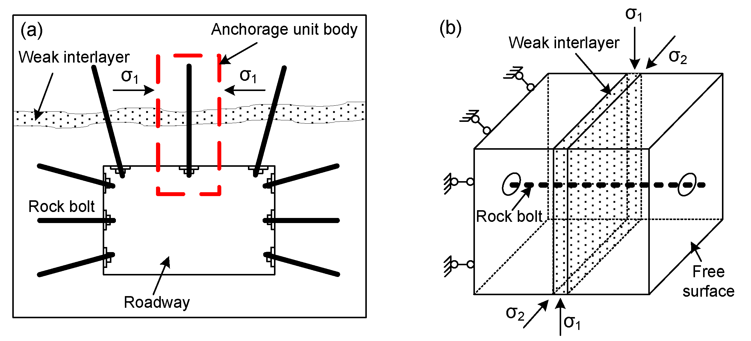
Figure 1. (a) Schematic diagram of unit anchorage; (b) Test prototype and mechanical model.
Minerals 11 00496 g001
Figure 2. Experimental system.
Minerals 11 00496 g002
Figure 3. (a,b) the lateral and rear restraint sub-system; (c) normal displacement of lateral restraint plates; (d) normal displacement of rear restraint plate.
Minerals 11 00496 g003
Figure 4. Distribution of weak interlayer with different dip angles (a) αw = 15°; (b) αw = 30°; (c) αw = 45° and (d) αw = 90°.
Minerals 11 00496 g004
Figure 5. (a) Mode bolt used in experimental; (b) Stress–strain curve of bolt.
Minerals 11 00496 g005
Figure 6. Typical stress–strain curves of bolted samples (a) without weak interlayer (Sample T-1); (b) with 25 mm thick weak interlayer (Sample T-6).
Minerals 11 00496 g006
Figure 7. The σp, E, Dp, and DE for weak interlayer with different thicknesses (a) peak strength of the samples; (b) weakening effect index of weak interlayer on sample peak strength; (c) elastic modulus of the samples; (d) weakening effect index of weak interlayer on sample elastic modulus.
Minerals 11 00496 g007
Figure 8. The σp, E, Dp, and DE for weak interlayer with different uniaxial compressive strength: (a) peak strength of the samples; (b) weakening effect index of weak interlayer on sample peak strength; (c) elastic modulus of the samples; (d) weakening effect index of weak interlayer on sample peak strength.
Minerals 11 00496 g008
Figure 9. The σp, E, Dp, and DE for weak interlayer with different dip angles: (a) peak strength of the samples; (b) weakening effect index of weak interlayer on sample peak strength; (c) elastic modulus of the samples; (d) weakening effect index of weak interlayer on sample peak strength.
Minerals 11 00496 g009
Figure 10. Sketch diagram of region for the specimens containing a weak interlayer.
Minerals 11 00496 g010
Figure 11. Failure characteristics of samples containing weak interlayers with different thicknesses: (a) tw = 0 mm; (b) tw = 5 mm; (c) tw = 10 mm; (d) tw = 15 mm; (e) tw = 20 mm; (f) tw = 25 mm.
Minerals 11 00496 g011
Figure 12. Failure characteristics of samples containing weak interlayer with different uniaxial compressive strength: (a) σw = 0.22 MPa; (b) σw = 0.46 MPa; (c) σw = 0.80 MPa; (d) σw = 1.27 MPa; (e) σw =1.74 MPa; (f) σw = 2.02 MPa.
Minerals 11 00496 g012
Figure 13. Failure mode of samples containing weak interlayer with different dip angles: (a) α = 15°; (b) α = 30°; (c) α = 45°; (d) α = 90°.
Minerals 11 00496 g013
Figure 14. Evolution of bolt axial force: (a,b) Sample T-1; (c,d) Sample T-6.
Minerals 11 00496 g014
Figure 15. Evolution of bolt bending moment: (a,b) Sample T-1; (c,d) Sample T-6.
Minerals 11 00496 g015
Table 1. Mechanical parameters of prototype materials.
LithologyE/GPaσc/MPaσt/MPac/MPaφγ/(kN/m3)
Sandstone20.26~32.8553.85~79.533.50~5.355.35~8.8338.4~45.025
Mudstone4.04~10.259.78~12.801.20~2.001.25~2.3419.8~22.525
(Note: E: elastic modulus; σc: uniaxial compressive strength; σt: tensile strength; c: cohesion; φ: internal friction angle; γ: unit weight.)
Table 2. Mechanical parameters of the similar materials.
TypeSand: Cement: GypsumE/MPaσc/MPaσt/MPac/MPaϕ
Hard rock4.5:1:09407.210.992.6427.77
Weak interlayer3: 0.5: 0.53602.020.250.4916.88
4: 0.6: 0.43101.740.220.4518.19
4: 0.5: 0.51901.270.170.3624.56
4: 0.4: 0.61100.800.120.1631.10
6: 0.5: 0.5700.460.060.1228.61
6: 0.4: 0.6200.220.030.0826.06
Note: E: elastic modulus; σc: uniaxial compressive strength; σt: tensile strength; c: cohesion; φ: internal friction angle.
Table 3. Three experimental cases and corresponding parameters.
Case No.Sampleσw/MPatw/mmαw
IS-10.22300
S-20.46
S-30.80
S-41.27
S-51.74
S-62.02
IIT-10.2200
T-25
T-310
T-415
T-520
T-625
T-730
IIIA-10.22300
A-215
A-330
A-445
A-590
Table 4. The σp, E, Dp, and DE for weak interlayer with different thicknesses.
Thickness of Weak Interlayer tw (mm)051015202530
Peak strength of the sample σp (MPa)14.9613.3212.2611.7011.2410.8410.50
Elastic modulus of the sample E (GPa)1.431.301.231.171.111.071.04
Weakening effect index of WI on sample peak strength Dp (%)010.9618.05 21.7924.8727.5429.81
Weakening effect index of WI on sample elastic modulus DE (%)09.0913.9918.1822.325.1727.27
Table 5. The σp, E, Dp, and DE for weak interlayer with different uniaxial compressive strength.
Uniaxial Compressive Strength of Weak Interlayer σw (MPa)0.220.460.801.271.742.02
Peak strength of the sample σp (MPa)10.5010.9011.2611.5811.7912.01
Elastic modulus of the sample E (GPa)1.041.081.131.181.251.31
Weakening effect index of weak interlayer on sample peak strength Dp (%)29.8127.1424.7322.5921.1919.72
Weakening effect index of weak interlayer on sample elastic modulus DE (%)27.2724.4820.9817.4812.598.39
Table 6. The σp, E, Dp, and DE for weak interlayer with different dip angles.
Dip angle of weak interlayer αw (°)015304590
Peak strength of the sample σp (MPa)10.509.188.588.369.34
Elastic modulus of the sample E (GPa)1.040.890.810.780.91
Weakening effect index of weak interlayer on sample peak strength Dp (%)29.81 38.64 42.65 44.12 37.57
Weakening effect index of weak interlayer on sample elastic modulus DE (%)27.27 37.76 43.36 45.45 36.36
Publisher’s Note: MDPI stays neutral with regard to jurisdictional claims in published maps and institutional affiliations.