Biosignatures in Subsurface Filamentous Fabrics (SFF) from the Deccan Volcanic Province, India


 ,
,  ,
,  ,
, 
Abstract
1. Introduction
2. Geological Setting and Occurrence of SFF
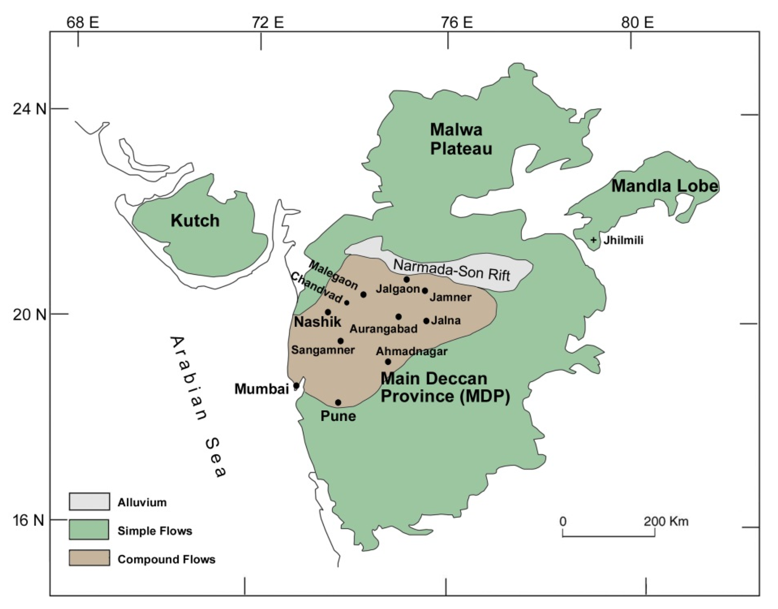
2.1. Geological Setting
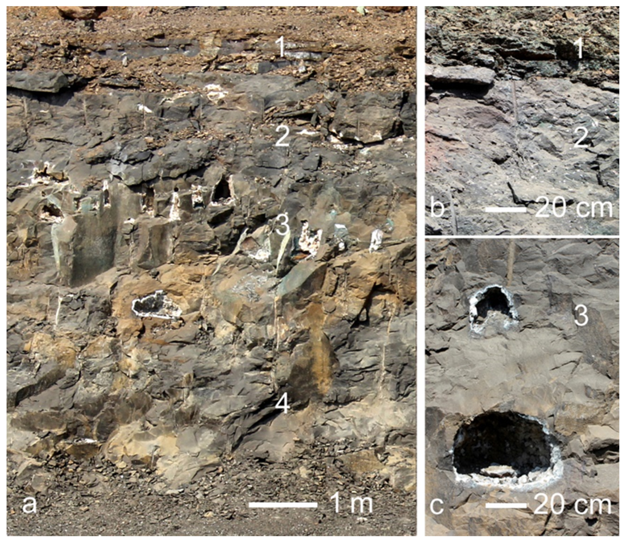
2.2. Occurrence of SFF in the DVP
3. Materials and Methods
3.1. Sample Material
3.2. Analytical Methods
4. Results
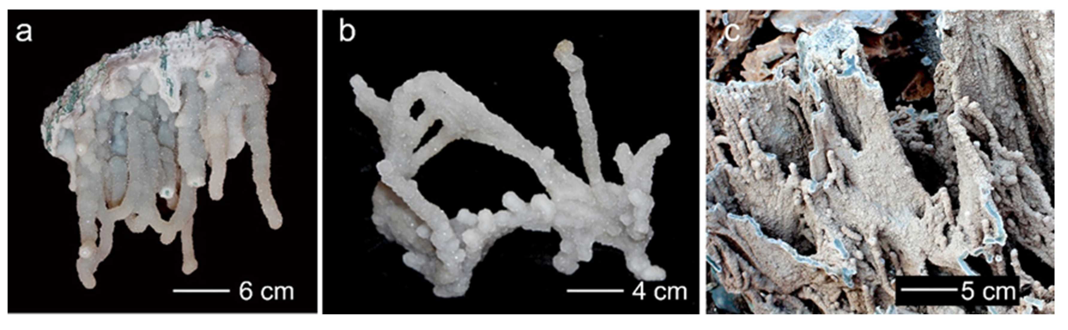
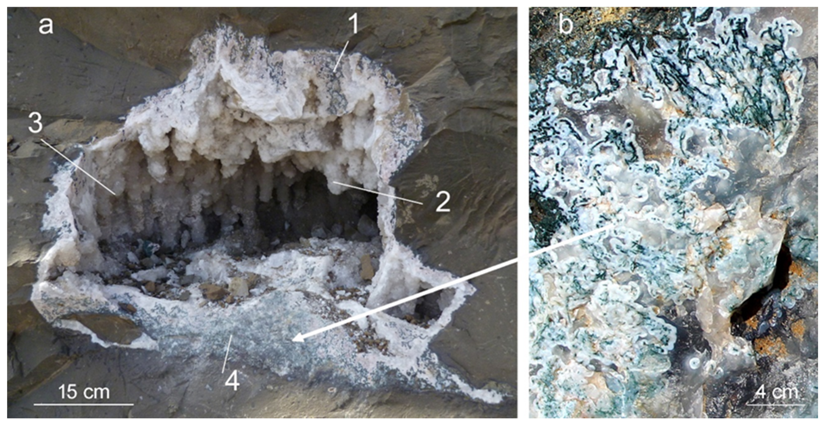
4.1. Morphology of SFF
4.2. Mineralogical Composition and Micro-Texture of SFF
4.2.1. Jalgaon/Savda
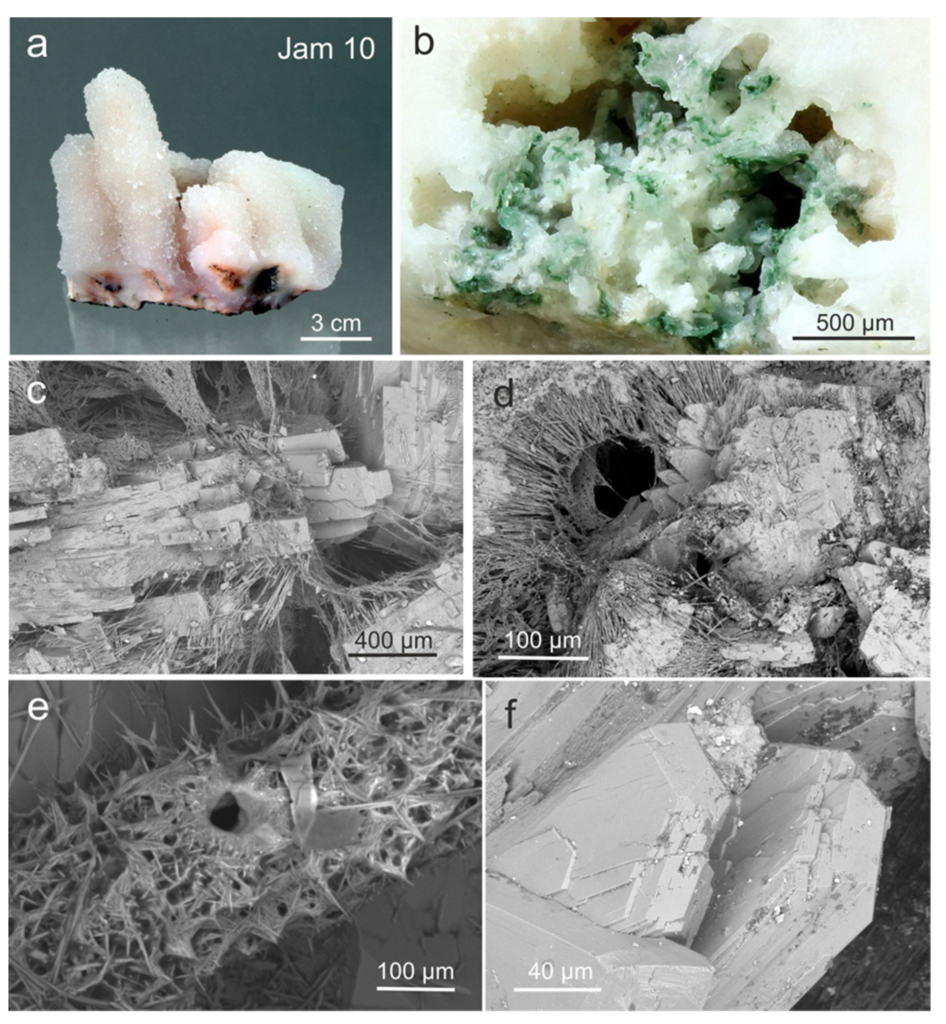
4.2.2. Jamner
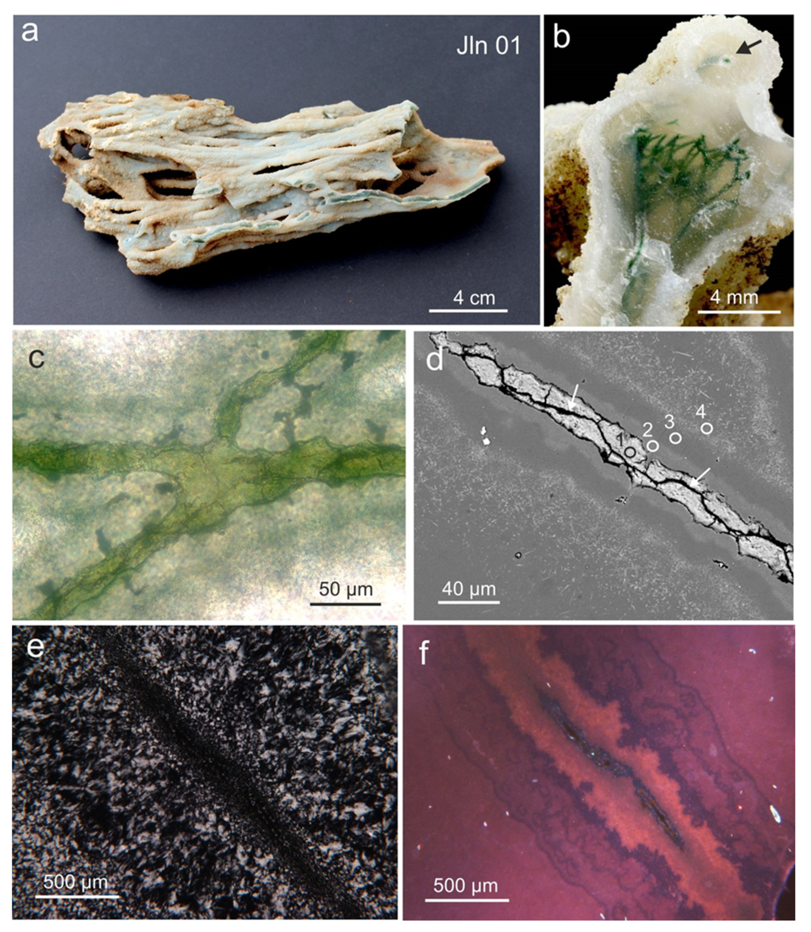
4.2.3. Jalna
4.3. Evaluation of Possible Biosignatures in SFF
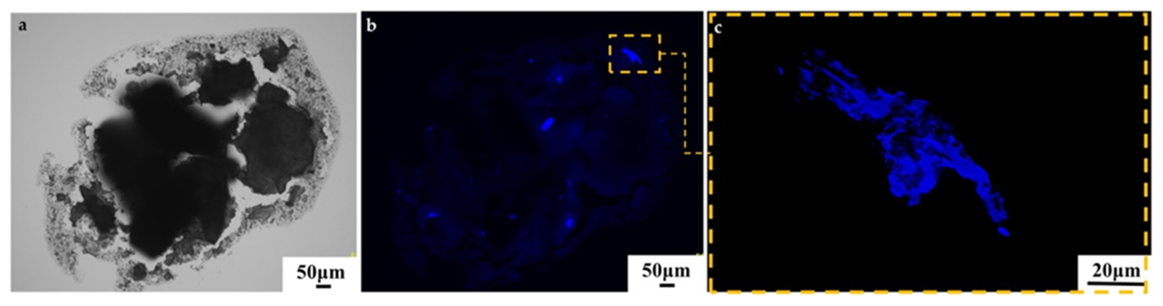
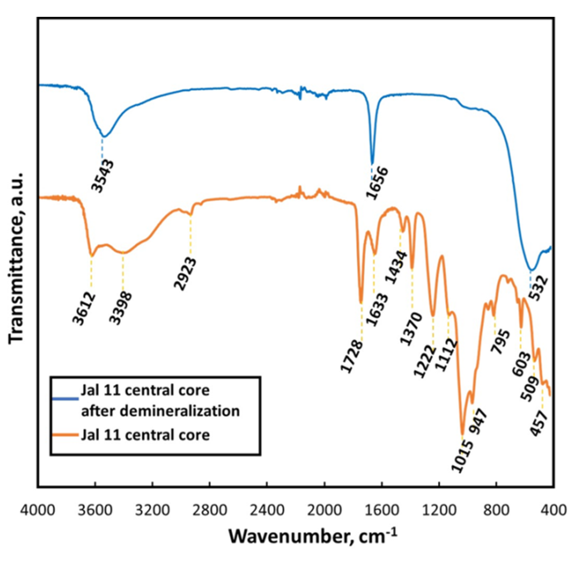
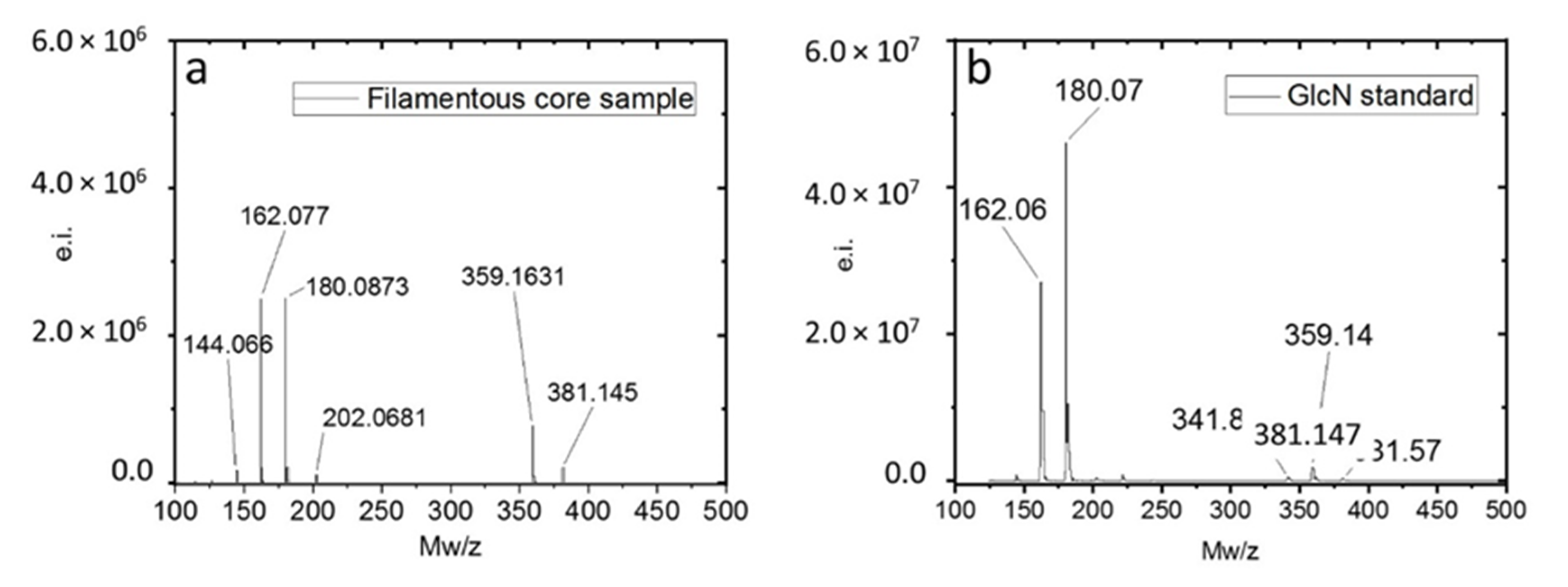
4.3.1. Identification of Organic Residues in the Filamentous Cores
4.3.2. Morphometric Analysis of Filamentous Fabrics
5. Discussion
5.1. Chemical Development and Mineralization Sequence of SFF
5.2. SFF Micro-Structure
5.3. Biogenic Origin and Formation Mechanism of SFF
6. Conclusions
Supplementary Materials
Author Contributions
Funding
Acknowledgments
Conflicts of Interest
References
- Hofmann, B.A. Subsurface filamentous fabrics. In Encyclopedia of Geobiology, Dordrecht; Reitner, J., Thiel, V., Eds.; Springer: Berlin/Heidelberg, Germany, 2011; pp. 851–853. [Google Scholar] [CrossRef]
- Sukheswala, R.N.; Avasia, R.K.; Gangopadhyay, M. Zeolites and associated secondary minerals in the Deccan Traps of Western India. Miner. Mag. 1974, 39, 658–671. [Google Scholar] [CrossRef][Green Version]
- Ottens, B. Die drusenmineralien aus dem spilitbasalt von Bombay/Indien. Der Aufschluß 1998, 49, 133–149. [Google Scholar]
- Ottens, B. Minerals of the deccan traps India. Miner. Rec. 2003, 34, 1–82. [Google Scholar]
- Ottens, B.; Götze, J.; Schuster, R.; Krenn, K.; Hauzenberger, C.; Zsolt, B.; Vennemann, T. Exceptional multi stage mineralization of secondary minerals in cavities of flood basalts from the Deccan Volcanic Province, India. Minerals 2019, 9, 351. [Google Scholar] [CrossRef]
- Morteani, G.; Kostitsyn, Y.; Preinfalk, C.; Gilg, H.A. The genesis of the amethyst geodes at Artigas (Uruguay) and the paleohydrology of the Guaraní aquifer: Structural, geochemical, oxygen, carbon, strontium isotope and fluid inclusion study. Int. J. Earth Sci. 2009, 99, 927–947. [Google Scholar] [CrossRef]
- Hofmann, B.A.; Farmer, J.D. Filamentous fabrics in low-temperature mineral assemblages: Are they fossil biomarkers? Implications for the search for a subsurface fossil record on the early Earth and Mars. Planet Space Sci. 2000, 48, 1077–1086. [Google Scholar] [CrossRef]
- Hofmann, B.A.; Farmer, J.D.; Von Blanckenburg, F.; Fallick, A.E. Subsurface filamentous fabrics: An evaluation of possible modes of origins based on morphological and geochemical criteria, with implications for exopalaeontology. Astrobiology 2008, 8, 87–117. [Google Scholar] [CrossRef]
- Shet, H.C. Flood basalts and large igneous provinces from deep mantle plumes. Tectonophysics 1999, 311, 1–29. [Google Scholar] [CrossRef]
- Sheth, H.C. Large Igneous Provinces (LIPs): Definition, Recommended Terminology, and a Hierarchical Classification. Earth-Science Reviews 2007, 85, 117–124. [Google Scholar] [CrossRef]
- Subbarao, K.V. Deccan Volcanic Province; Geological Society of India: Bangalore, India, 1999. [Google Scholar]
- Pande, K. Age and duration of the deccan traps, India: A review of radiometric and palaeomagnetic constraints. Proc. Indian Acad. Sci. Earth Planet Sci. 2002, 111, 115–123. [Google Scholar] [CrossRef]
- Sheth, H.C. The deccan beyond the plume hypothesis. Geophys. Res. Abstr. 2006, 8, 2. [Google Scholar]
- Chenet, A.L.; Courtillot, V.; Fluteau, F.; Gérard, M.; Quidelleur, X.; Khadri, S.F.R.; Subbarao, K.V.; Thordarson, T. Determination of rapid Deccan eruptions across the Cretaceous-Tertiary boundary using paleomagnetic secular variation: 2. Constraints from analysis of eight new sections and synthesis for a 3500-m-thick composite section. J. Geophys. Res. Solid Earth 2009, 114, 1–38. [Google Scholar] [CrossRef]
- Keller, G.; Adatte, T.; Gardin, S.; Bartolini, A.; Bajpai, S. Main Deccan volcanism phase ends near the K–T boundary: Evidence from the Krishna–Godavari Basin, SE India. Earth Planet. Sci. Lett. 2008, 268, 293–311. [Google Scholar] [CrossRef]
- Bondre, N.R.; Duraiswami, R.A.; Dole, G. Morphology and emplacement of flows from the Deccan Volcanic Province, India. Bull. Volcanol. 2004, 66, 29–45. [Google Scholar] [CrossRef]
- Vanderkluysen, L.; Mahoney, J.J.; Hooper, P.R.; Sheth, H.; Ray, R. The Feeder System of the Deccan Traps (India): Insights from Dike Geochemistry. J. Pet. 2011, 52, 315–343. [Google Scholar] [CrossRef]
- Keller, G.; Sahni, A.; Bajpai, S. Deccan volcanism, the KT mass extinction and dinosaurs. J. Biosci. 2009, 34, 709–728. [Google Scholar] [CrossRef] [PubMed]
- Chenet, A.-L.; Quidelleur, X.; Fluteau, F.; Courtillot, V.; Bajpai, S. 40K–40Ar dating of the Main Deccan large igneous province: Further evidence of KTB age and short duration. Earth Planet. Sci. Lett. 2007, 263, 1–15. [Google Scholar] [CrossRef]
- Jay, A.; Widdowson, M. Stratigraphy, structure and volcanology of the SE Deccan continental flood basalt province: Implications for eruptive extent and volumes. J. Geol. Soc. 2008, 165, 177–188. [Google Scholar] [CrossRef]
- Sprain, C.J.; Renne, P.R.; Vanderkluysen, L.; Pande, K.; Self, S.; Mittal, T. The eruptive tempo of Deccan volcanism in relation to the Cretaceous-Paleogene boundary. Science 2019, 363, 866–870. [Google Scholar] [CrossRef] [PubMed]
- Jay, A.E. Volcanic Architecture of the Deccan Traps, Western Maharashtra, India: An Integrated Chemostratigraphic and Palaeomagnetic Study. Ph.D. Thesis, The Open University, Milton Keynes, UK, 2005. [Google Scholar]
- Beane, J.E.; Turner, C.A.; Hooper, P.R.; Subbarao, K.V.; Walsh, J.N. Stratigraphy, composition and form of the Deccan Basalts, Western Ghats, India. Bull. Volcanol. 1986, 48, 61–83. [Google Scholar] [CrossRef]
- Hooper, P.R. The winds of change: The Deccan traps, a personal perspective. In Deccan Volcanic Province; Subbarao, K.V., Ed.; Memoir of the Geological Society of India: Bangalore, India, 1999. [Google Scholar]
- Bondre, N.R.; Duraiswami, R.A.; Dole, G. A brief comparison of lava flows from the Deccan Volcanic Province and the Columbia-Oregon Plateau Flood Basalts: Implications for models of flood basalt emplacement. J. Earth Syst. Sci. 2004, 113, 809–817. [Google Scholar] [CrossRef]
- Deshmuk, S.S. Petrographic variations in Compound flows of Deccan Traps and their significance. GSI Mem. 1988, 10, 305–319. [Google Scholar]
- Patro, B.P.K.; Sarma, S.V.S. Trap thickness and the subtrappean structures related to mode of eruption in the Deccan Plateau of India: Results from magnetotellurics. Earth Planets Space 2007, 59, 75–81. [Google Scholar] [CrossRef]
- Merchant, H. Strucural Geology and Petrology of the Island Bombay and Surrounding Areas, Unpublished. Ph.D. Thesis, Bombay University, Mumbai, India, 1977. [Google Scholar]
- Cripps, J.; Widdowson, M.; Spicer, R.; Jolley, D. Coastal ecosystem responses to late stage Deccan Trap volcanism: The post K–T boundary (Danian) palynofacies of Mumbai (Bombay), west India. Palaeogeogr. Palaeoclim. Palaeoecol. 2005, 216, 303–332. [Google Scholar] [CrossRef]
- Keller, G.; Khosla, S.C.; Sharma, R.; Khosla, A. Early Danian planktic foraminifera from Cretaceous-Tertiary intertrappean beds at Jhilmili, Chhindwara District, Madhya Pradesh, India. J. Foraminifer. Res. 2009, 39, 40–55. [Google Scholar] [CrossRef]
- Khosla, A.; Verma, O. Paleobiota from the deccan volcano-sedimentary sequences of India: Paleoenvironments, age and paleobiogeographic implications. Hist. Biol. 2015, 27, 898–914. [Google Scholar] [CrossRef]
- Walker, G.P.L. Some observations and interpretations on the deccan traps. Mem. Geol. Soc. India 1969, 43, 367–395. [Google Scholar]
- Jeffery, K.L.; Henderson, P.; Subbarao, K.V.; Walsh, J.N. The zeolites of deccan basalts—A study of their distribution. In Deccan Flood Basalts; Subbarao, K.V., Ed.; Geological Society of India: Bangalore, India, 1988; pp. 151–162. [Google Scholar]
- James, S.; Walsh, J.N. Zeolites from the deccan basalts: Chemistry and formation. Mem. Geol. Soc. India 1999, 43, 803–817. [Google Scholar]
- Ottens, B. Indien, Mineralien und Fundstellen; Weise Verlag: München, Germany, 2011; p. 384. ISBN 978-3-921656-76-1. [Google Scholar]
- Melluso, L.; Barbieri, M.; Beccaluva, L. Chemical evolution, petrogenesis, and regional chemical correlations of the flood basalt sequence in the central Deccan Traps, India. J. Earth Syst. Sci. 2004, 113, 587–603. [Google Scholar] [CrossRef]
- Chenet, A.-L.; Fluteau, F.; Courtillot, V.; Gérard, M.; Subbarao, K.V. Determination of rapid Deccan eruptions across the Cretaceous-Tertiary boundary using paleomagnetic secular variation: Results from a 1200-m-thick section in the Mahabaleshwar escarpment. J. Geophys. Res. Space Phys. 2008, 113. [Google Scholar] [CrossRef]
- Self, S.; Keszthelyi, L.; Thordarson, T. The importance of pāhoehoe. Annu. Rev. Earth Planet. Sci. 1998, 26, 81–110. [Google Scholar] [CrossRef]
- Sahagian, D.L.; Proussevitch, A.A.; Carslon, W.D. Analysis of visicular basalts and lava empalacement processes for application as a palaobarometer/paleoaltimeter. J. Geol. 2002, 110, 671–685. [Google Scholar] [CrossRef]
- Neuser, R.D.; Bruhn, F.; Götze, J.; Habermann, D.; Richter, D.K. Kathodolumineszenz: Methodik und anwendung. Zent. Geol. Paläontologie Part I 1995, 1, 287–306. [Google Scholar]
- Williams, A.J.; Sumner, D.Y.; Alpers, C.N.; Karunatillake, S.; Hofmann, B.A. Preserved filamentous microbial biosignatures in the Brick Flat Gossan, Iro Mountain. Calif. Astrobiol. 2015, 15, 337–668. [Google Scholar]
- Ehrlich, H.; Rigby, J.K.; Botting, J.P.; Tsurkan, M.; Werner, C.; Schwille, P.; Petrásek, Z.; Pisera, A.; Simon, P.; Sivkov, V.; et al. Discovery of 505-million-year old chitin in the basal demosponge Vauxia gracilenta. Sci. Rep. 2013, 3, 17–20. [Google Scholar] [CrossRef]
- Wysokowski, M.; Zatoń, M.; Bazhenov, V.; Behm, T.; Ehrlich, A.; Stelling, A.L.; Hog, M.; Ehrlich, H. Identification of chitin in 200-million-year-old gastropod egg capsules. Paleobiology 2014, 40, 529–540. [Google Scholar] [CrossRef]
- Melluso, L.; Sethna, S.F. Mineral compositions in the Deccan igneous rocks of India: An overview. In Topics in Igneous Petrology; Ray, J., Sen, G., Ghosh, B., Eds.; Springer: Dordrecht, The Netherlands, 2011; pp. 135–139. [Google Scholar] [CrossRef]
- Götze, J. Chemistry, textures and physical properties of quartz—Geological interpretation and technical application. Mineral. Mag. 2009, 73, 645–671. [Google Scholar] [CrossRef]
- Sterflinger, K. Fungi as geologic agents. Geomicrobiol. J. 2000, 17, 97–124. [Google Scholar] [CrossRef]
- Ehrlich, H.; Ilan, M.; Maldonado, M.; Muricy, G.; Bavestrello, G.; Kljajic, Z.; Carballo, J.L.; Schiaparelli, S.; Ereskovsky, A.; Schupp, P.; et al. Three-dimensional chitin-based scaffolds from Verongida sponges (Demospongiae: Porifera). Part I. Isolation and identification of chitin. Int. J. Biol. Macromol. 2010, 47, 132–140. [Google Scholar] [CrossRef]
- Ehrlich, H.; Maldonado, M.; Spindler, K.-D.; Eckert, C.; Hanke, T.; Born, R.; Goebel, C.; Simon, P.; Heinemann, S.; Worch, H. First evidence of chitin as a component of the skeletal fibers of marine sponges. Part I. Verongidae (demospongia: Porifera). J. Exp. Zool. Part B Mol. Dev. Evol. 2007, 308, 347–356. [Google Scholar] [CrossRef]
- Klinger, C.; Żółtowska-Aksamitowska, S.; Wysokowski, M.; Tsurkan, M.; Galli, R.; Petrenko, I.; Machałowski, T.; Ereskovsky, A.; Martinovic, R.; Muzychka, L.; et al. Express Method for Isolation of Ready-to-Use 3D Chitin Scaffolds from Aplysina archeri (Aplysineidae: Verongiida) Demosponge. Mar. Drugs 2019, 17, 131. [Google Scholar] [CrossRef] [PubMed]
- Rickert, D.; Schlueter, M.; Wallmann, K. Dissolution kinetics of biogenic silica from the water column to the sediments. Geochim. Cosmochim. Acta 2002, 66, 439–455. [Google Scholar] [CrossRef]
- Sprynskyy, M.; Pomastowski, P.; Hornowska, M.; Król, A.; Rafińska, K.; Buszewski, B. Naturally organic functionalized 3D biosilica from diatom microalgae. Mater. Des. 2017, 132, 22–29. [Google Scholar] [CrossRef]
- Budiarti, H.A.; Puspitasari, R.N.; Hatta, A.; Sekartedjo; Risanti, D.D. Synthesis and Characterization of TiO2 @SiO2 and SiO2 @TiO2 Core-Shell Structure Using Lapindo Mud Extract via Sol-Gel Method. Procedia Eng. 2017, 170, 65–71. [Google Scholar] [CrossRef]
- Hernandez-Ortiz, M.; Hernández-Padrón, G.; Bernal, R.; Cruz-Vázquez, C.; Castano, V. Nanocrystalline mimetic opals: Synthesis and comparative characterization vs. natural stones. Int. J. Basic Appl. Sci. 2015, 4, 238. [Google Scholar] [CrossRef]
- Heredia, A.; Figueira, E.; Rodrigues, C.T.; Rodríguez-Galván, A.; Basiuk, V.A.; Vrieling, E.G.; Almeida, S.F. Cd2+ affects the growth, hierarchical structure and peptide composition of the biosilica of the freshwater diatom Nitzschia palea (Kützing) W. Smith. Phycol. Res. 2012, 60, 229–240. [Google Scholar] [CrossRef]
- Aliabadi, M.; Shagholani, H.; Lehi, A.Y. Synthesis of a novel biocompatible nanocomposite of graphene oxide and magnetic nanoparticles for drug delivery. Int. J. Boil. Macromol. 2017, 98, 287–291. [Google Scholar] [CrossRef]
- Di Mario, F.; Rapanà, P.; Tomati, U.; Galli, E. Chitin and chitosan from Basidiomycetes. Int. J. Boil. Macromol. 2008, 43, 8–12. [Google Scholar] [CrossRef]
- Gupta, B.S.; Jelle, B.; Gao, T. Application of ATR-FTIR Spectroscopy to Compare the Cell Materials of Wood Decay Fungi with Wood Mould Fungi. Int. J. Spectrosc. 2015, 2015, 1–7. [Google Scholar] [CrossRef]
- Hassainia, A.; Satha, H.; Boufi, S. Chitin from Agaricus bisporus: Extraction and characterization. Int. J. Boil. Macromol. 2018, 117, 1334–1342. [Google Scholar] [CrossRef]
- Ehrlich, H.; Maldonado, M.; Parker, A.R.; Kulchin, Y.N.; Schilling, J.; Köhler, B.; Skrzypczak, U.; Simon, P.; Reiswig, H.M.; Tsurkan, M.; et al. Supercontinuum Generation in Naturally Occurring Glass Sponges Spicules. Adv. Opt. Mater. 2016, 4, 1608–1613. [Google Scholar] [CrossRef]
- Neinhuis, C.; Nickerl, J.; Tsurkan, M.; Werner, C. The multi-layered protective cuticle of Collembola: A chemical analysis. J. R. Soc. Interface 2014, 11, 20140619. [Google Scholar]
- Machałowski, T.; Wysokowski, M.; Tsurkan, M.; Galli, R.; Schimpf, C.; Rafaja, D.; Brendler, E.; Viehweger, C.; Aksamitowska, Ż.; Petrenko, I.; et al. Spider Chitin: An Ultrafast Microwave-Assisted Method for Chitin Isolation from Caribena versicolor Spider Molt Cuticle. Molecules 2019, 24, 3736. [Google Scholar] [CrossRef] [PubMed]
- Ehrlich, H.; Bazhenov, V.; Debitus, C.; De Voogd, N.; Galli, R.; Tsurkan, M.; Wysokowski, M.; Meissner, H.; Bulut, E.; Kaya, M.; et al. Isolation and identification of chitin from heavy mineralized skeleton of Suberea clavata (Verongida: Demospongiae: Porifera) marine demosponge. Int. J. Boil. Macromol. 2017, 104, 1706–1712. [Google Scholar] [CrossRef]
- Seyfried, W.; Bischoff, J. Low temperature basalt alteration by sea water: An experimental study at 70 °C and 150 °C. Geochim. Cosmochim. Acta 1979, 43, 1937–1947. [Google Scholar] [CrossRef]
- Polgári, M.; Hein, J.R.; Nemeth, T.; Pál-Molnár, E.; Vigh, T. Celadonite and smectite formation in the Úrkút Mn-carbonate ore deposit (Hungary). Sediment. Geol. 2013, 294, 157–163. [Google Scholar] [CrossRef][Green Version]
- Treiman, A.H.; Morris, R.V.; Agresti, D.G.; Graff, T.G.; Achilles, C.N.; Rampe, E.B.; Bristow, T.F.; Ming, D.W.; Blake, D.F.; Vaniman, D.T.; et al. What lurks in the martian rocks and soil? Investigations of sulfates, phosphates, and perchlorates. Am. Mineral. 2014, 99, 2234–2250. [Google Scholar] [CrossRef]
- Peretyazhko, T.; Sutter, B.; Morris, R.V.; Agresti, D.G.; Le, L.; Ming, D.W. Smectite formation from basaltic glass under acidic conditions on early Mars. Geochim. Cosmochim. Acta 2016, 173, 37–49. [Google Scholar] [CrossRef]
- Pradeep, K.S.; Devdutt, V.U.; Vibhuti, W. Alteration of volcanic glass to well-crystallized ferrosaponite in the vesicles of the deccan trap basalts at bhuleshwar ghat section, pune district, maharashtra. J. Geol. Soc. India 2016, 88, 22–28. [Google Scholar]
- Rykart, R. Quarz-Monographie. Ott Verlag Thun Aufl. 1995, 2, 462. [Google Scholar]
- Lillie, R.S. The formation of structures resembling organic growths by means of electrolytic local action in metals, and the general physiological significance and control of this type of action. Biol. Bull. 1917, 33, 135–186. [Google Scholar] [CrossRef][Green Version]
- Pagano, J.J.; Thouvenel-Romans, S.; Steinbock, O. Compositional analysis of copper–silica precipitation tubes. Phys. Chem. Chem. Phys. 2007, 9, 110–116. [Google Scholar] [CrossRef]
- Cartwright, J.H.E.; Escribano, B.; Sainz-Díaz, C.I. Chemical-Garden Formation, Morphology, and Composition. I. Effect of the Nature of the Cations. Langmuir 2011, 27, 3286–3293. [Google Scholar] [CrossRef]
- García-Ruiz, J.M.; Kubatko, K.-A.H.; Helean, K.B.; Navrotsky, A.; Burns, P. Self-Assembled Silica-Carbonate Structures and Detection of Ancient Microfossils. Science 2003, 302, 1194–1197. [Google Scholar] [CrossRef] [PubMed]
- García-Ruiz, J.M.; Melero-García, E.; Hyde, S.T. Morphogenesis of Self-Assembled Nanocrystalline Materials of Barium Carbonate and Silica. Science 2009, 323, 362–365. [Google Scholar] [CrossRef]
- Satoh, H.; Tsukamoto, K.; García-Ruiz, J.M. Formation of chemical gardens on granitic rock: A new type of alteration for alkaline systems. Eur. J. Miner. 2014, 26, 415–426. [Google Scholar] [CrossRef]
- McMahon, S. Earth’s earliest and deepest purported fossils may be iron-mineralized chemical gardens. Proc. R. Soc. B Biol. Sci. 2019, 286. [Google Scholar] [CrossRef]
- Ehrlich, H.L. Geomicrobiology, 2nd ed.; Marcel Dekker: New York, NY, USA, 1990; p. 646. [Google Scholar]
- Barns, S.M.; Nierzwicki-Bauer, S.A. Microbial diversity in ocean, surface and subsurface environments. Rev. Mineral. 1997, 35, 35–79. [Google Scholar]
- Müller, A.; Polgári, M.; Gucsik, A.; Nagy, S.; Veres, M.; Pál-Molnár, E.; Götze, J.; Cserháti, C.; Németh, T.; Hámor-Vidó, M. Cathodoluminescent features and Raman spectroscopy of Miocene hydrothermal biomineralization embedded in cryptocrystalline silica varieties, Central Europe, Hungary. In Micro-Raman Spectroscopy and Luminescence Studies in the Earth and Planetary Sciences; Gucsik, A., Ed.; AIP Conference Proceedings: Melville, NY, USA, 2009. [Google Scholar]
- Reolid, M.; Abad, I. Glauconitic laminated crusts from hydrothermal alteration of Jurassic pillow-lavas (Betic Cordillera, S Spain): A microbial influence case. J. Iber. Geol. 2014, 40, 389–408. [Google Scholar] [CrossRef]
- Fisk, M.R.; Giovannoni, S.J.; Thorseth, I.H. Alteration of Oceanic Volcanic Glass: Textural Evidence of Microbial Activity. Science 1998, 281, 978–980. [Google Scholar] [CrossRef]
- Furnes, H.; Staudigel, H.; Thorseth, I.H.; Torsvik, T.; Muehlenbachs, K.; Tumyr, O. Bioalteration of basaltic glass in the oceanic crust. Geochem. Geophys. Geosystems 2001, 2, 8. [Google Scholar] [CrossRef]
- Furnes, H.; Banerjee, N.R.; Muehlenbachs, K.; Staudigel, H.; De Wit, M.J. Early Life Recorded in Archean Pillow Lavas. Science 2004, 304, 578–581. [Google Scholar] [CrossRef]
- Banerjee, N.R.; Muehlenbachs, K. Tuff life: Bioalteration in volcaniclastic rocks from the Ontong Java Plateau. Geochem. Geophys. Geosystems 2003, 4, 4. [Google Scholar] [CrossRef]
- Benzerara, K.; Menguy, N.; Banerjee, N.; Tyliszczak, T.; Brown, G.; Guyot, F. Alteration of submarine basaltic glass from the Ontong Java Plateau: A STXM and TEM study. Earth Planet. Sci. Lett. 2007, 260, 187–200. [Google Scholar] [CrossRef]
- Crovisier, J.; Honnorez, J.; Eberhart, J. Dissolution of basaltic glass in seawater: Mechanism and rate. Geochim. Cosmochim. Acta 1987, 51, 2977–2990. [Google Scholar] [CrossRef]
- Fisk, M.R.; Crovisier, J.-L.; Honnorez, J. Experimental abiotic alteration of igneous and manufactured glasses. Comptes Rendus Geosci. 2013, 345, 176–184. [Google Scholar] [CrossRef]
- Ivarsson, M.; Lausmaa, J.; Lindblom, S.; Broman, C.; Holm, N. Fossilized Microorganisms from the Emperor Seamounts: Implications for the Search for a Subsurface Fossil Record on Earth and Mars. Astrobiology 2008, 8, 1139–1157. [Google Scholar] [CrossRef]
- Fernández-Remolar, D.; Prieto-Ballesteros, O.; Rodríguez, N.; Gomez, F.; Amils, R.; Gómez-Elvira, J.; Stoker, C.R. Underground Habitats in the Río Tinto Basin: A Model for Subsurface Life Habitats on Mars. Astrobiology 2008, 8, 1023–1047. [Google Scholar] [CrossRef]
- Williams, A.J.; Alpers, C.N.; Sumner, D.Y.; Campbell, K.M. Filamentous Hydrous Ferric Oxide Biosignatures in a Pipeline Carrying Acid Mine Drainage at Iron Mountain Mine, California. Geomicrobiol. J. 2016, 34, 193–206. [Google Scholar] [CrossRef]
- Kretzschmar, M. Fossile Pilze in Eisen-Stromatolithen von Warstein (Rheinisches Schiefergebirge). Facies 1982, 7, 237–259. [Google Scholar] [CrossRef]
- Baele, J.-M.; Boulvain, F.; Jong, J.D.; Matielli, N.; Papier, S.; Préat, A. Iron microbial mats in Modern and Phanerozoic environments. In Instruments, Methods, and Missions for Astrobiology; Hoover, R.B., Levin, G.V., Rozanov, A.Y., Davies, P.C.W., Eds.; XI, Proceedings of SPIE: Bellingham, WA, USA, 2008. [Google Scholar]
- Zhou, X.; Chen, D.; Tang, D.; Dong, S.; Guo, C.; Guo, Z.; Zhang, Y. Biogenic Iron-Rich Filaments in the Quartz Veins in the Uppermost Ediacaran Qigebulake Formation, Aksu Area, Northwestern Tarim Basin, China: Implications for Iron Oxidizers in Subseafloor Hydrothermal Systems. Astrobiology 2015, 15, 523–537. [Google Scholar] [CrossRef] [PubMed]
- Reysenbach, A.L.; Cady, S.L. Microbiology of ancient and modern hydrothermal systems. Trends Microbiol. 2001, 9, 79–86. [Google Scholar] [CrossRef]
- Cartwright, J.H.E.; García-Ruiz, J.M.; Novella, M.L.; Otálora, F. Formation of chemical gardens. J. Colloid Interface Sci. 2002, 256, 351–359. [Google Scholar] [CrossRef]
- Barge, L.M.; Cardoso, S.S.S.; Cartwright, J.H.E.; Cooper, G.J.T.; Cronin, L.; De Wit, A.; Doloboff, I.J.; Escribano, B.; Goldstein, E.R.; Haudin, F.; et al. From Chemical Gardens to Chemobrionics. Chem. Rev. 2015, 115, 8652–8703. [Google Scholar] [CrossRef] [PubMed]
- Kellermeier, M.; Cölfen, H.; García-Ruiz, J.M. Silica Biomorphs: Complex Biomimetic Hybrid Materials from “Sand and Chalk”. Eur. J. Inorg. Chem. 2012, 2012, 5123–5144. [Google Scholar] [CrossRef]
- Krepski, S.T.; Emerson, D.; Hredzak-Showalter, P.L.; Luther, G.W.; Chan, C.S. Morphology of biogenic iron oxides records microbial physiology and environmental conditions: Toward interpreting iron microfossils. Geobiology 2013, 11, 457–471. [Google Scholar] [CrossRef]
- Johannessen, K.C.; McLoughlin, N.; Vullum, P.E.; Thorseth, I.H. On the biogenicity of Fe-oxyhydroxide filaments in silicified low-temperature hydrothermal deposits: Implications for the identification of Fe-oxidizing bacteria in the rock record. Geobiology 2019, 18, 31–53. [Google Scholar] [CrossRef]
- Perry, R.S.; McLoughlin, N.; Lynne, B.Y.; Sephton, M.; Oliver, J.D.; Perry, C.C.; Campbell, K.A.; Engel, M.H.; Farmer, J.D.; Brasier, M.D.; et al. Defining biominerals and organominerals: Direct and indirect indicators of life. Sediment. Geol. 2007, 201, 157–179. [Google Scholar] [CrossRef]
- Oggerin, M.; Rodriguez, N.; Del Moral, C.; Amils, R. Fungal jarosite biomineralization in Río Tinto. Res. Microbiol. 2014, 165, 719–725. [Google Scholar] [CrossRef]
- Li, H.; Hu, S.; Polizzotto, M.L.; Chang, X.; Shen, Q.; Ran, W.; Yu, G.-H. Fungal biomineralization of montmorillonite and goethite to short-range-ordered minerals. Geochim. Cosmochim. Acta 2016, 191, 17–31. [Google Scholar] [CrossRef]
- Bindschedler, S.; Cailleau, G.; Verrecchia, E.P. Role of Fungi in the Biomineralization of Calcite. Minerals 2016, 6, 41. [Google Scholar] [CrossRef]
- Mistri, A.; Quirin, M.E.C.; Mukherjee, A. Carbonate biomineralization and heavy metal remediation by calcifying fungi isolated from karstic caves. Ecol. Eng. 2017, 103, 106–117. [Google Scholar]
- Tazaki, K. Clays, microorganisms, and biomineralization. In Handbook of Clay Science; Bergaya, F., Theng, B.K.G., Lagaly, G., Eds.; Elsevier: Amsterdam, The Netherlands, 2006; pp. 477–497. [Google Scholar]
- Köhler, B.; Singer, A.; Stoffers, P. Biogenic nontronite from marine white smoker chimneys. Clays Clay Miner. 1994, 42, 689–701. [Google Scholar] [CrossRef]
- Ueshima, M.; Tazaki, K. Possible role of microbial polysaccharides in nontronite formation. Clays Clay Miner. 2001, 49, 292–299. [Google Scholar] [CrossRef]
- Schultze-Lam, S.; Fortin, D.; Davis, B.S.; Beveridge, T.J. Mineralization of bacterial surfaces. Chem. Geol. 1996, 132, 171–181. [Google Scholar] [CrossRef]
- Kawano, M.; Tomita, K. Microbiotic formation of silicate minerals in the weathering environment of a pyroclastic deposit. Clays Clay Miner. 2002, 50, 99–110. [Google Scholar] [CrossRef]
- Ferris, F.G.; Beveridge, T.J.; Fyfe, W.S. Iron-silica crystallite nucleation by bacteria in a geothermal sediment. Nature 1986, 320, 609–611. [Google Scholar] [CrossRef]
- Konhauser, K.O.; Urrutia, M.M. Bacterial clay authigenesis: A common biogeochemical process. Chem. Geol. 1999, 161, 399–413. [Google Scholar] [CrossRef]
- Urrutia, M.M.; Beveridge, T.J. Formation of fine-grained meal and silicate precipitates on abacterial surface (Bacillus subtilis). Chem. Geol. 1994, 116, 261–280. [Google Scholar] [CrossRef]
- Skinner, H.C.W.; Jahren, A.H. Biomineralization. In Treatise on Geochemistry; Elsevier: Amsterdam, The Netherlands, 2003; pp. 117–184. [Google Scholar]
- Melton, E.D.; Swanner, E.D.; Behrens, S.; Schmidt, C.; Kappler, A. The interplay of microbially mediated and abiotic reactions in the biogeochemical Fe cycle. Nat. Revies Microbiol. 2014, 12, 797–808. [Google Scholar] [CrossRef]
- Chan, C.S.; De Stasio, G.; Welch, S.A.; Girasole, M.; Frazer, B.H.; Nesterova, M.V.; Fakra, S.; Banfield, J.F. Microbial saccharides template assembly of nanocrystal fibres. Science 2004, 303, 1656–1658. [Google Scholar] [CrossRef] [PubMed]
- Tazaki, K. Biomineralization of layer silicates and hydrated Fe/Mn Oxides in Microbial Mats: An Electron Microsopical Study. Clays Clay Miner. 1997, 45, 203–212. [Google Scholar] [CrossRef]
- Konhauser, K.O. Diversity of bacterial iron mineralization. Earth Sci. Rev. 1998, 43, 91–121. [Google Scholar] [CrossRef]


| Sample No. | Sample Material | Locality | Figure | SEM | XRD | Morphometric Analysis | Bio-Analysis |
|---|---|---|---|---|---|---|---|
| Aur 02 | Filament | Aurangabad | X | X | |||
| Jal 01 | Filament | Jalgaon | SEMu | ||||
| Jal 04 | Filament | Jalgaon | SEMu | ||||
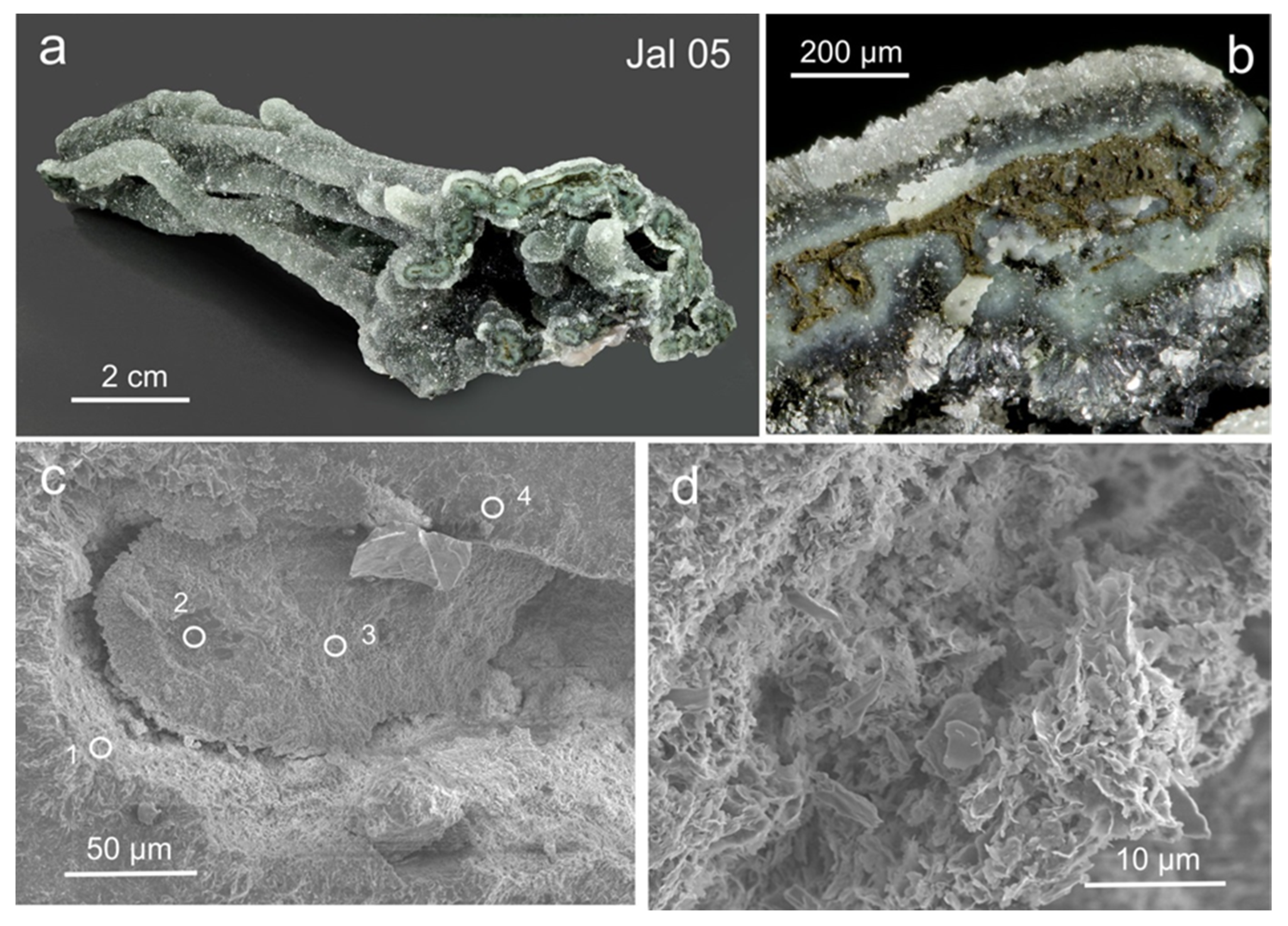
| Jal 05 | Filament | Jalgaon | Figure 13 | SEMc-EDX | X | X | |
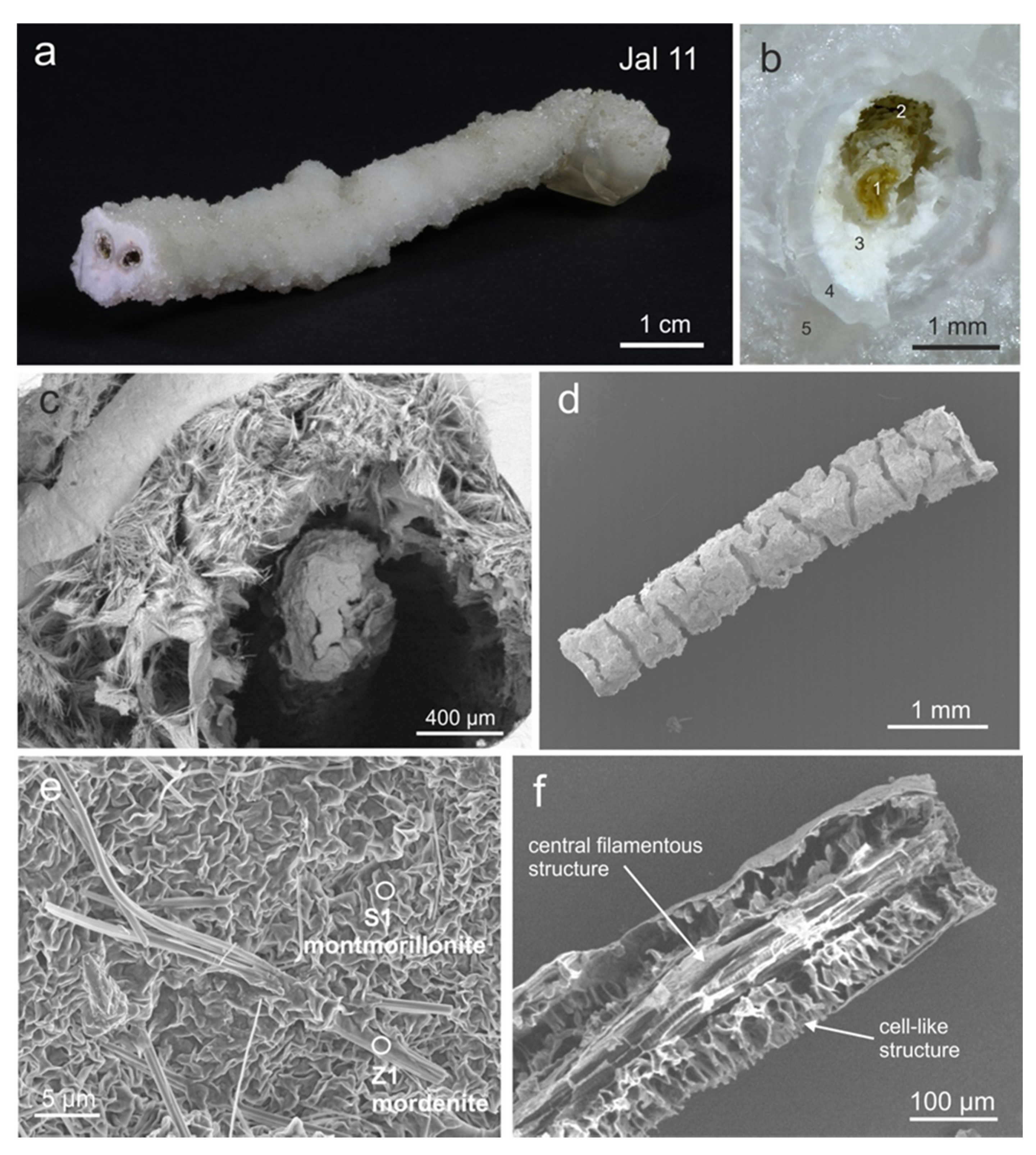
| Jal 11 | Filament | Jalgaon | Figure 11 | SEMu SEMc-EDX | X | ||
| Jal 17 | Filament | Jalgaon | SEMc-EDX | X | |||
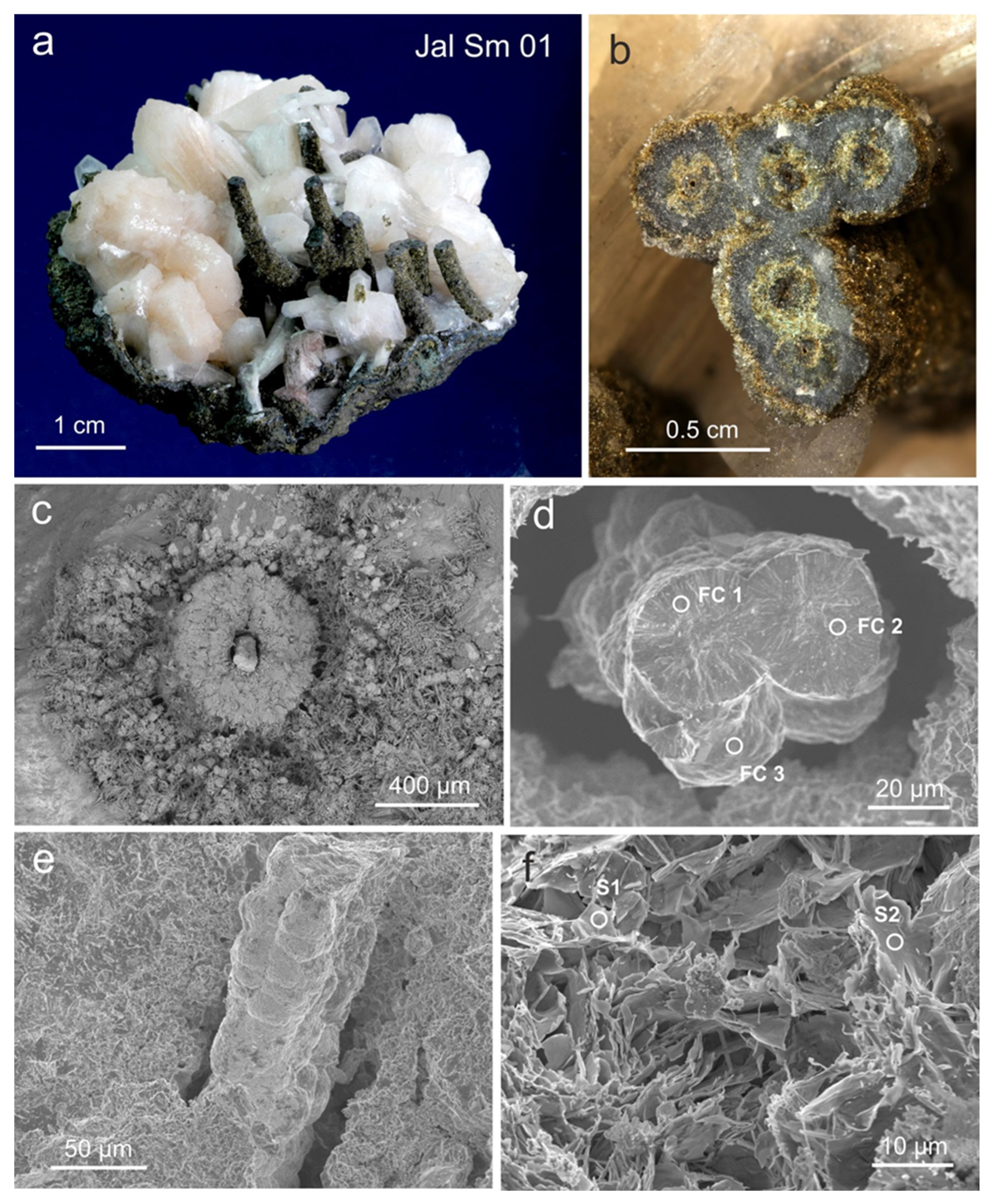
| Jal Sm 01 | Filament | Jalgaon | Figure 14 | SEMu-EDX SEMc-EDX | X | X | |
| Jal Sm 03 | Filament | Jalgaon | SEMu-EDX | X | |||
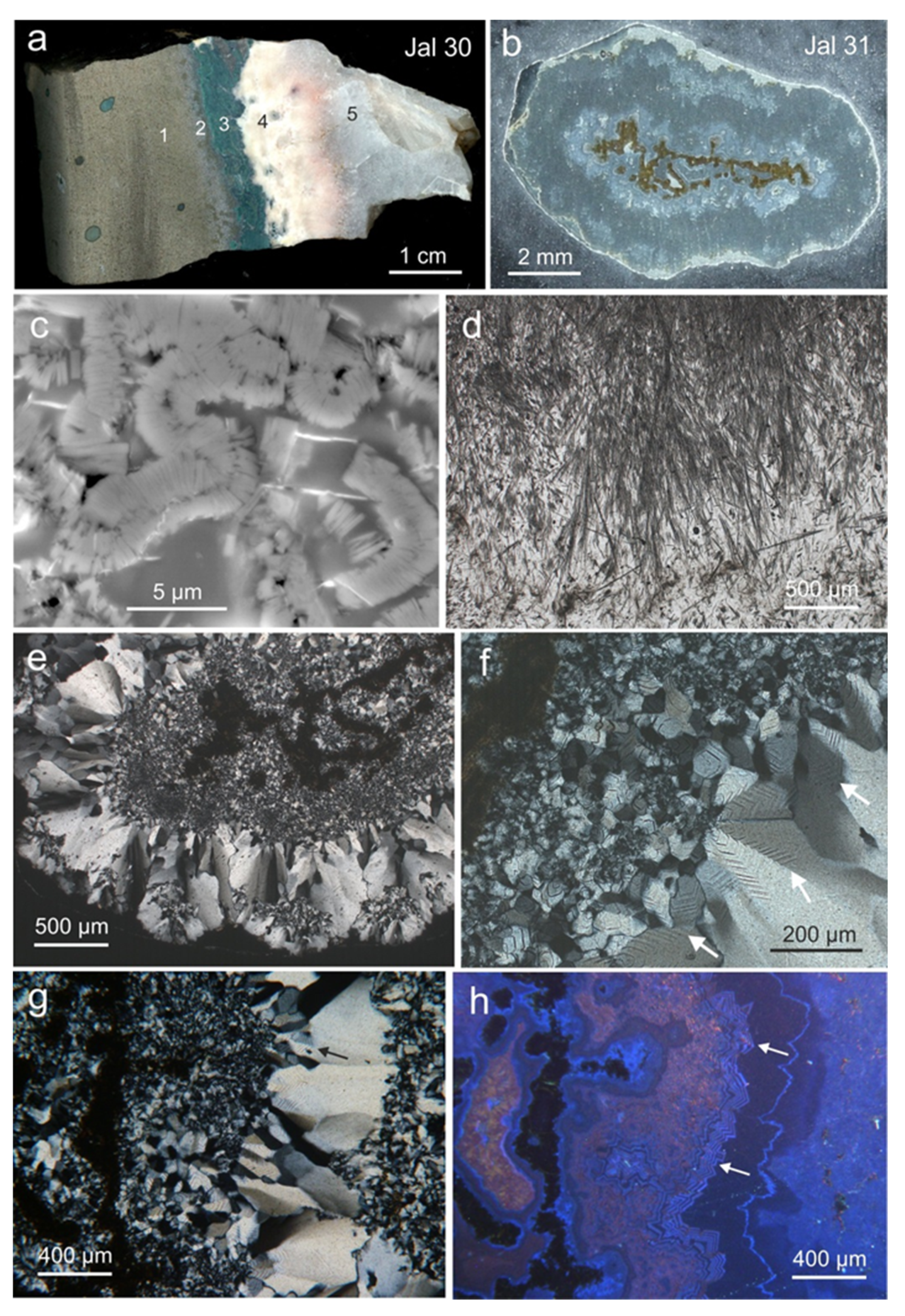
| Jal 30 | Cross-section Cavity wall | Jalgaon | Figure 7 | SEMc-EDX | X | ||
| Jal 31 | Filament | Jalgaon | Figure 7 | SEMc-EDX | X | ||
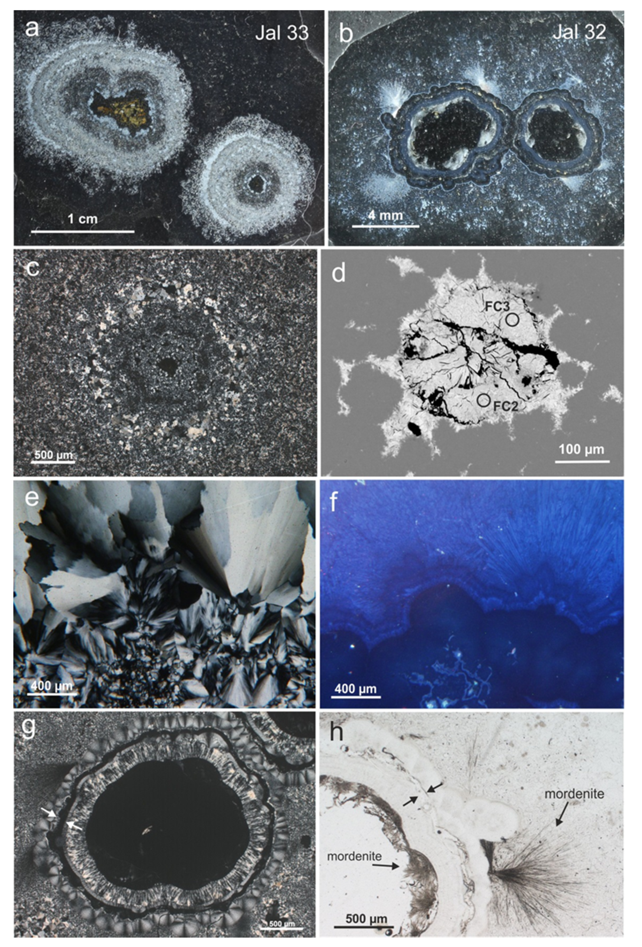
| Jal 32 | Filament | Jalgaon | Figure 10 | SEMc-EDX | |||
| Jal 33 | Filament | Jalgaon | Figure 10 | SEMc-EDX | |||
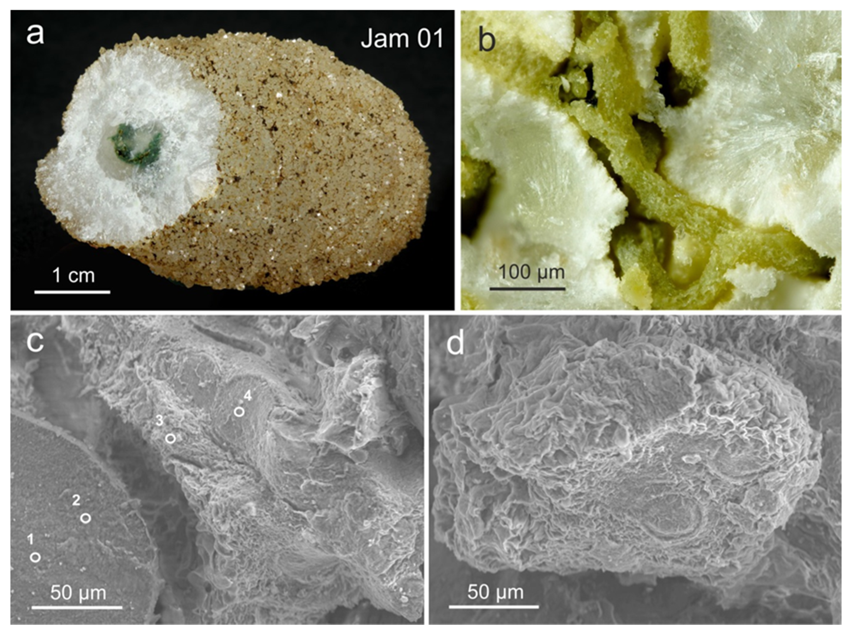
| Jam 01 | Filament | Jamner | Figure 16 | SEMu-EDX SEMc-EDX | X | ||
| Jam 10 | Filament | Jamner | Figure 17 | SEMc-EDX | X | ||
| Jam 17 | Filament | Jamner | X | ||||
| Jln 01 | “Moss agate” | Jalna | Figure 18 | SEMc-EDX | X | X | |
| 31226 | “Moss agate” | Jalgaon | X |
| Sample | Innermost Diameter of Filaments (Mean) (µm) | Standard Deviation of Diameter (µm) | Relative Standard Deviation | Number of Filament Diameters Measured | Filament Shape Measured |
|---|---|---|---|---|---|
| Jal 17 | <20 | - | - | - | - |
| Jln 01a | 1.58 | 0.44 | 0.28 | 19 | - |
| Jln 01b | 4.87 | 1.24 | 0.26 | 38 | - |
| Jal 05 | <40 | - | - | - | - |
| Jam 17 | <5 | - | - | - | - |
| Aur 2 | 1.26 | 0.45 | 0.36 | 36 | X |
| 31226 (round) | 2.36 | 0.90 | 0.38 | 51 | X |
| 31226 (square) | 4.72 | 2.22 | 0.47 | 64 | X |
| Samples | Diameter (µm) | Standard Deviation | Bending (°/µm) | Direction Changes (mm) | Biogenicity (%) 1 |
|---|---|---|---|---|---|
| (a) Abiogenic reference samples (23 samples, 1840 diameters, 345 shapes) | |||||
| Mean | 15.0 | 0.72 | 0.27 | 2.37 | |
| Median | 5.6 | 0.66 | 0.08 | 0.03 | |
| Minimum | 0.5 | 0.29 | 0.00 | 0.00 | |
| Maximum | 134.6 | 1.40 | 1.66 | 21.0 | 14 |
| (b) Biological reference samples (17 samples, 830 diameters, 266 shapes) | |||||
| Mean | 2.1 | 0.17 | 1.74 | 44.78 | |
| Median | 2.0 | 0.16 | 0.71 | 15.80 | |
| Minimum | 1.0 | 0.10 | 0.31 | 5.90 | |
| Maximum | 3.3 | 0.30 | 15.40 | 344.00 | 100 |
| (c) Biogenicity criteria | |||||
| 1.0–3.4 | <0.43 | >0.30 | >5.0 | ||
| (d) Samples from the Deccan trap basalts | |||||
| 31226 moss agate a | 4.70 | 0.47 (64) | 0.34 | 10.3 (21) | 50 |
| 31226 moss agate b | 2.40 | 0.38 (51) | 0.83 | 21.5 (8) | 100 |
| Aur01 filamentous | 1.26 | 0.36 (36) | 1.26 | 44.3 (22) | 100 |
| Jln01 filamentous fabric 2 | 1.58 | 0.28 (19) | 1.13 | 48.8 (7) | 75 |
| 4.90 | 0.26 (38) | ||||
© 2020 by the authors. Licensee MDPI, Basel, Switzerland. This article is an open access article distributed under the terms and conditions of the Creative Commons Attribution (CC BY) license (http://creativecommons.org/licenses/by/4.0/).
Share and Cite
Götze, J.; Hofmann, B.; Machałowski, T.; Tsurkan, M.V.; Jesionowski, T.; Ehrlich, H.; Kleeberg, R.; Ottens, B. Biosignatures in Subsurface Filamentous Fabrics (SFF) from the Deccan Volcanic Province, India. Minerals 2020, 10, 540. https://doi.org/10.3390/min10060540
Götze J, Hofmann B, Machałowski T, Tsurkan MV, Jesionowski T, Ehrlich H, Kleeberg R, Ottens B. Biosignatures in Subsurface Filamentous Fabrics (SFF) from the Deccan Volcanic Province, India. Minerals. 2020; 10(6):540. https://doi.org/10.3390/min10060540
Chicago/Turabian StyleGötze, Jens, Beda Hofmann, Tomasz Machałowski, Mikhail V. Tsurkan, Teofil Jesionowski, Hermann Ehrlich, Reinhard Kleeberg, and Berthold Ottens. 2020. "Biosignatures in Subsurface Filamentous Fabrics (SFF) from the Deccan Volcanic Province, India" Minerals 10, no. 6: 540. https://doi.org/10.3390/min10060540
APA StyleGötze, J., Hofmann, B., Machałowski, T., Tsurkan, M. V., Jesionowski, T., Ehrlich, H., Kleeberg, R., & Ottens, B. (2020). Biosignatures in Subsurface Filamentous Fabrics (SFF) from the Deccan Volcanic Province, India. Minerals, 10(6), 540. https://doi.org/10.3390/min10060540