Article

Fracture Propagation and Morphology Due to Non-Aqueous Fracturing: Competing Roles between Fluid Characteristics and In Situ Stress State

1
Key Laboratory of Shale Gas Exploration, Ministry of Natural Resources, Chongqing Institute of Geology and Mineral Resources, Chongqing 401120, China
2
State Key Laboratory of Coal Mine Disaster Dynamics and Control, Chongqing University, Chongqing 400044, China
3
National Joint Local Engineering Research Center for Shale Gas Exploration and Development, Chongqing Institute of Geology and Mineral Resources, Chongqing 401120, China
4
Department of Energy and Mineral Engineering, EMS Energy Institute, and G3 Center, The Pennsylvania State University, University Park, State College, PA 16802, USA
*
Author to whom correspondence should be addressed.
Minerals 2020, 10(5), 428; https://doi.org/10.3390/min10050428
Submission received: 13 April 2020 / Revised: 7 May 2020 / Accepted: 9 May 2020 / Published: 10 May 2020
(This article belongs to the Special Issue Deep Saline CO2 Sequestration: Mechanisms and Coupling Behaviours)

Abstract

:
Non-aqueous or gaseous stimulants are alternative working fluids to water for hydraulic fracturing in shale reservoirs, which offer advantages including conserving water, avoiding clay swelling and decreasing formation damage. Hence, it is crucial to understand fluid-driven fracture propagation and morphology in shale formations. In this research, we conduct fracturing experiments on shale samples with water, liquid carbon dioxide, and supercritical carbon dioxide to explore the effect of fluid characteristics and in situ stress on fracture propagation and morphology. Moreover, a numerical model that couples rock property heterogeneity, micro-scale damage and fluid flow was built to compare with experimental observations. Our results indicate that the competing roles between fluid viscosity and in situ stress determine fluid-driven fracture propagation and morphology during the fracturing process. From the macroscopic aspect, fluid-driven fractures propagate to the direction of maximum horizontal stress direction. From the microscopic aspect, low viscosity fluid easily penetrates into pore throats and creates branches and secondary fractures, which may deflect the main fracture and eventually form the fracture networks. Our results provide a new understanding of fluid-driven fracture propagation, which is beneficial to fracturing fluid selection and fracturing strategy optimization for shale gas hydraulic fracturing operations.

1. Introduction

Shale gas production has substantial growth in North America due to the advances in horizontal drilling and multi-stage fracturing technology [1,2,3]. However, in some shale formations, impairment of productivity has been observed due to the use of water-based fracturing fluid: (1) water is trapped in the near-wellbore area and hinder the mass transport of oil and gas from the fractures to the wellbores; (2) clay minerals swell after water invades into formations which results to the formation permeability decrease [4,5,6,7]. Moreover, environmental issues, such as groundwater contamination and potentially induced seismicity by wastewater re-injection have been reported [8,9,10]. As an alternative to water-based fracturing fluids, non-aqueous or gaseous fluids, such as nitrogen (N2), liquid carbon dioxide(L-CO2) and supercritical carbon dioxide (Sc-CO2) have been proposed as potential fracturing fluid candidates [11,12,13,14].
Experimental results indicated that the nitrogen gas fracturing method may result in a lower breakdown pressure and induce complicated fractures compared with the traditional water-based fracturing fluid [15,16]. Furthermore, nitrogen gas fracturing is highly beneficial in shallow formations and depleted gas reservoirs due to energizing properties [17]. Experimental studies found that the liquid carbon dioxide fracturing method results in lower breakdown pressure and more well-connected fracture networks in shale and PMMA (polymethyl methacrylate) materials [18,19]. Moreover, due to the high expansion ability of L-CO2, once the fracture initiates near the fluid injection borehole, the L-CO2 easily penetrates into the rock matrix and induces the sample breakdown [20]. The recent numerical method which combines pore-scale and continuum-scale also supports the experimental observations of liquid carbon dioxide fracturing [21,22,23]. The experimental investigations of supercritical carbon dioxide (Sc-CO2) fracturing indicates that Sc-CO2 may induce greater fracture propagation and reduces flow blockages and potentially increase the desorption of CH4 [24,25]. Furthermore, the lower breakdown pressure and complex fracture propagation are observed due to the low viscosity and infiltration properties of supercritical carbon dioxide [26]. Moreover, the potential carbon dioxide sequestration in depleted shale gas wells and formations offer an opportunity to reduce the greenhouse gas effect [27]. Nonetheless, the existing explanation on the process of fluid-driven fracture propagation remains qualitative and no systemic research has been conducted with shale rock samples to shed light on the fracture morphology in shale reservoirs due to the non-aqueous fracturing method. Moreover, poor explanations are made to date to explain the effect of fluid characteristics on the propagation of fluid-driven fractures.
Accordingly, in this research, we use H2O, L-CO2, and Sc-CO2 to perform fracturing tests in shale samples under various combinations of in situ stress. Computed tomography (CT) technology is further used to analyze fracture morphology. Then, a numerical model that couples rock property heterogeneity, micro-scale damage, and fluid flow is built to run numerical simulation works and compare with experimental observations. Finally, the effect of fluid characteristics and in situ stress on the fluid-driven fracture propagation and morphology are carefully theoretically investigated.

2. Experimental Research

In this part, we firstly reported the apparatus and sample preparation procedures for fracturing experiments. Subsequently, we described how we performed the fracturing experiments with H2O, L-CO2, and Sc-CO2 under various combinations of the stress state. Finally, the fracture morphology is extracted by the CT scanning method.

2.1. Apparatus and Sample Preparation

The fracturing experiments are performed with a triaxial loading system that can independently apply axial stress, confining stress, and perform fluid injection for fracturing (Figure 1). Hand pumps are used to deploy confining stress and axial stress separately, which includes the maximum horizontal stress (σH), minimum horizontal stress (σh) and vertical stress (σV). An ISCO 260D plunger pump (manufactured by Teledyne ISCO, Lincoln, NE, USA) is used to inject fracturing fluid (Sc-CO2, L-CO2 or distilled water) at a constant flow rate for each test.
Shale samples are collected from an outcrop of the Lower Silurian Longmaxi Formation, located in the Sichuan Basin (northwest of Chongqing, China). The samples are cut into a 200 mm × 200 mm × 200 mm cubic shape, as shown in Figure 2a. A blind central borehole is drilled whose length is 110 mm. The boreholes are perpendicular to bedding planes and analog as fracturing boreholes. The petrophysical properties and mineral compositions of the samples are listed in Table 1 and Table 2.

2.2. Experimental Procedure

Shale samples are collected from the Lower Silurian Longmaxi Formation, located in the Sichuan Basin (northwest of Chongqing, China). The samples are cut into a 200 mm × 200 mm × 200 mm cubic shape, as shown in Figure 2a. A blind central borehole is drilled whose length is 110 mm. The boreholes are perpendicular to bedding planes and analog as fracturing boreholes.
Since the experiments aim to investigate the effect of fluid characteristics and in situ stress on fracture propagation and morphology, the conditions for experiments are summarized in Table 3. It should be noted that even though the stress state cannot fully represent the in situ stress, the variation in horizontal stress difference is enough to investigate the role of fluid characteristics on the fracturing process and morphology [28,29,30,31,32].
We use three types of fracturing fluid, namely water, liquid carbon dioxide (L-CO2), and supercritical carbon dioxide (Sc-CO2) to perform fracturing experiments firstly. A heating unit is used to heat the injection fluid with a temperature controller. In the cases of water and liquid carbon dioxide fracturing tests, the system temperature is set at 25 °C. For supercritical carbon dioxide fracturing tests, the system temperature is set as 60 °C to take the carbon dioxide into the supercritical state. Before each test, the sample will be placed in the tank for 24 h to make the sample has a stable temperature. We inject the particular fluid with a constant flow rate of 30.0 mL/min into the shale sample until the injection pressure markedly decreases due to the initiation of fractures. Experiments 1–3 are used to identify the effect of fracturing fluid properties on the fracture propagation morphology. Moreover, we change the stress state while still using supercritical carbon dioxide in experiments 4–7, to identify the role of in situ stress on the fracture distribution and morphology in shale.
After each fracturing test, the samples are removed from thermotank for the CT scanning experiments. The scanning plane is perpendicular to the borehole direction, which is shown in Figure 2b.

2.3. Experimental Results

The relationship between fluid pressure and the elapsed time for seven fracturing experiments are summarized in Figure 3. Under the same stress state, H2O returns the highest breakdown pressure (29.25 MPa), followed by L-CO2 (18.70 MPa), with Sc-CO2 exhibiting the lowest breakdown pressure at 14.11 MPa. When injecting Sc-CO2 as the fracturing fluid, the results indicate that with the increase of horizontal stress difference, a decreasing trend of breakdown pressure is observed.
The CT scanning images for different fracturing fluid under the same stress state were extracted. The vertical stress is 12.0 MPa, the maximum horizontal stress is 10.0 MPa and the minimum horizontal stress is 8.0 MPa. Then, to make the fractures clearly observable, we developed MATLAB code to adjust the threshold value of CT images and got the gray images in Figure 4. The images indicate that at the same stress state, H2O creates a smooth main fracture which propagates parallel to the maximum horizontal stress direction. This similar phenomenon has been commonly observed by other researchers [29]. The L-CO2 fluid also creates the main fracture. However, the induced fractures are not as smooth as the fractures driven by H2O. Also, the fracture deflection phenomenon is observed in the direction of minimum horizontal stress and some secondary fractures and branches are also observed for Sc-CO2 fracturing, as shown in Figure 4c. We believe more fractures and a complex fracture pattern could be formed by the Sc-CO2 fracturing method [26]. For L-CO2 fracturing, the fracture morphology between traditional hydraulic fracturing and Sc-CO2 fracturing, the main fracture could be formed with some branches and secondary fractures, but not as much as Sc-CO2 fracturing. Hence, the fluid characteristics play an important role in fracture propagation morphology.
Figure 5 shows the role of in situ stress on the fracture propagation morphology. When injecting the same fluid (Sc-CO2), the horizontal stress difference (maximum horizontal stress minus minimum horizontal stress) largely affects the propagation morphology for fluid-driven fracture propagation. When the horizontal stress difference is small, fracture networks are more likely formed, as shown in Figure 5a,b. However, with the increase of horizontal stress difference, the fracture propagates parallel to the direction of maximum horizontal stress direction, as shown in Figure 5c–e. This observation is similar to the previous research that the horizontal stress difference is the most important factor in determining the fluid-driven fracture propagation direction [29].
It should be also noted that even though the horizontal stress is 4.0 MPa, the main fracture is observed in Figure 5e, rather than the fracture networks. We can still observe some small branches and secondary fractures. This is the result of natural fractures or micro-fractures which exist before the hydraulic fracturing experiments. Based on the sedimentary characteristics, the natural fractures are well-developed. One limitation we must admit to that it is difficult to locate all natural fractures before the experiment since the CT images are extracted layer by layer.

3. Numerical Simulation Research

We cannot conduct experiments under all combinations of stress state for different kinds of fracturing fluids. Hence, it is essential to develop a numerical model to further characterize the role of fluid characteristics and stress state on the fracture propagation morphology. In this part, a numerical model coupling rock property heterogeneity, micro-scale damage, and fluid flow is built to run the simulation works and compare with experimental observations.

3.1. Governing Equations for Numerical Simulation

3.1.1. Governing Equations for Rock Deformation

Under fluid pressure conditions, based on poroelastic theory, the rock deformation could be expressed as the Navier-type equation [23]:
G u i , k k + G 1 2 ν u k , k i α p , i + f , i = 0
where u is the displacement; i, j, and k denote the space coordinates; G is the shear modulus of rock; ν is Poisson’s ratio of rock; α is the Biot coefficient; p is pore pressure and f is body force.

3.1.2. Governing Equations for Fluid Flow

The main difference between gas and fluid is compressibility. For conventional hydraulic fluid, like water and oil, the fluid has low compressibility. However, for gas like CO2 and N2, the large compressibility and phase change cannot be neglected.
For slightly compressible fluid flow in the rock, the governing equation could be built based on the mass balance equation of fluid and neglect effect of gravity, which is [22]:
( ϕ K f + 1 ϕ K s ) p t + ( k μ p ) = Q s
where Kf is the bulk modulus of fluid; Ks is the bulk modulus of rock; Φ is porosity; k is permeability; μ is fluid viscosity; p is fluid pressure; Qs is the gas source.
The governing equations for CO2 (compressible fluid) flow in rocks could be written as:
ϕ N p t + ( k μ ρ p ) = Q s
where N = R T ( δ 2 φ δ δ r + 2 δ φ δ r + 1 ) which is a variable related with residual part of Helmholtz free energy, φ r , and reduced density of CO2, δ , φ δ r and φ δ δ r are first and second derivatives of φ r concerning δ . A detailed explanation of this term is given in [22].

3.1.3. Damage Law for Rock

The damage law is defined at the microscopic scale which is detailed in [33]. Tensile damage and shear damage occur when REVs (representative elemental volume) satisfied the maximum tensile stress criteria or shear failure criterion, as defined by and shown in Figure 6 [33,34].
F 1 = ( σ h α p ) f t = 0 F 2 = ( σ H α p ) 1 + sin θ 1 sin θ ( σ h α p ) f c = 0
where σH and σh are maximum horizontal stress and minimum horizontal stress, ft and fc are axial tensile strength and axial compressive strength; θ is internal friction angle. F1 and F2 are threshold functions for tensile failure and shear failure occurs.
The elastic modulus of rock decreases with the evolution of damage, which could be expressed as:
E = ( 1 D ) E 0
where E0 is the initial elastic modulus and D is the damage variable. A constitutive law defining D is given in reference [22,33] and, therefore, is omitted here for brevity.

3.2. Numerical Simulation Model and Parameters

For a better representation of the realistic heterogeneity of shale samples, the elastic modulus, Poisson ratio, and strength parameters of each element in the numerical model follow the Weibull distribution. The probability density function of Weibull distribution is expressed as:
f ( u ) = m u 0 ( u u 0 ) m 1 e x p ( ( u u 0 ) m )
where u is the elastic modulus, Poisson ratio, and strength for each element, u0 is the average value, m is the homogeneity index parameter which describes the shape of the distribution.
Mathematically, the average value u0 is fixed in the Weibull distribution. Hence, the parameter m defines the degree of material homogeneity. The larger the value of m, the more homogeneous the material properties. Hence, if the sample is regarded as homogenous, the m value is always set as larger than 10, where the inhomogeneity properties will not largely affect the result. In our model, the shale rock samples are always inhomogeneous and the m is set as 5. Other physical, mechanical, and hydrological parameters of rock and fluids are obtained from previous experiments and summarized in Table 4. The geometry of the model is shown in Figure 7.
The original code is written with MATLAB. After that, the parameters related to the damage are also calculated by MATLAB to gain a better calculation speed. Finally, the related parameters are implemented by COMSOL Multiphysics software (Version 5.2a, COMSOL, Inc., Burlington, MA, USA) to complete the FEM (Finite Element Method) analysis.

3.3. Numerical Simulation Results

The numerical simulation results of fracture propagation and morphology for different fracturing fluid under the same stress state is shown in Figure 8. To extend the experimental content, we selected viscous oil, water, liquid carbon dioxide, supercritical carbon dioxide and nitrogen as the fracturing fluids. For all five kinds of fracturing fluid, the main fractures are formed, which propagates to the direction of maximum horizontal stress. However, when we use viscous oil and conventional water as the fracturing fluids, the smooth main fracture is formed without branches and secondary fractures, as indicated in Figure 8a,b. When the injection fluids change to liquid CO2, SC-CO2 and nitrogen gas, fractures initiate from the injection wellbore from several points, then the fractures propagate to the direction of maximum horizontal stress, as shown from Figure 8c–e. Moreover, the propagation morphology has longer pathways for supercritical carbon dioxide and nitrogen gas, which illustrate better propagation ability due to low fluid viscosity.
Figure 9 illustrates how horizontal stress difference affects fracture propagation morphology. When the horizontal stress is 0 and 1.0 MPa, fractures initiate from several points near the fluid injection wellbore and fracture networks are formed, as shown in Figure 9a,b. Moreover, the rock was damaged before the fracture across the whole sample. When the horizontal stress difference increases to 2.0 MPa, two fractures initiate near the injection wellbore; one propagates parallels to the direction of maximum horizontal stress and the other one’s propagation direction is relatively random, as shown in Figure 9c. One thing should be noted is that the fracture which propagates to the direction of maximum horizontal stress has longer pathways than the other fracture. This implies the role of stress on fracture propagation. When the horizontal stress difference changes to 3.0 MPa, a fracture perpendicular to the maximum horizontal stress direction is imitated near the injection wellbore. However, the fracture only propagates for a small distance, due to the stress restriction. When the horizontal difference is large at 4.0 MPa, a relatively smooth fracture is formed and tends to propagate parallel to the maximum horizontal stress direction.

4. Discussion

To further compare the experimental observations and numerical simulations results, we summarized them in combing figures, as presented in Figure 10 and Figure 11.
Figure 10 compares the fracture morphology based on experimental observations and numerical simulations where water, liquid CO2, and supercritical CO2 are injected into shale samples under vertical stress at 12.0 MPa, maximum horizontal stress at 10.0 MPa and minimum horizontal stress at 8.0 MPa. The fracture morphology images are similar between experimental results and simulation results when injecting water into shale samples, where a smooth main fracture is formed and fracture propagates to the direction of maximum horizontal stress. When the injection fluid is liquid CO2 and supercritical CO2, we can also observe the main fractures which propagate to the direction of the maximum horizontal stress direction. However, a fracture initiates from several weak points near the fluid injection borehole when we inject liquid carbon dioxide and supercritical carbon dioxide. As shown in Figure 10b, the fracture initiates from three points, which show an inverted “Y” shape fracture type. In Figure 10c, four (two groups) fractures are formed near the fluid injection borehole, which shows an “X” shape transverse fracture pattern. Furthermore, the apparent fracture width of supercritical carbon dioxide fracturing is larger than those of the fractures induced by water.
Besides the similarities between the experimental observations and numerical simulation results, some differences can also be found. In Figure 10c, the fracture deflection is much sharper than numerical results, which almost propagate to the direction of minimum horizontal stress. We contribute this phenomenon to the potential bedding planes. In our numerical simulation model, the shale heterogeneity is considered by introducing Gaussian distribution of element mechanical properties, namely elastic modulus and Poisson’s ratio. However, the potential pre-existing natural fractures and bedding planes in transversely isotropic shale may affect the hydraulic fracture propagation. In future works, we will consider this parameter.
Figure 11 compares the fracture morphology where the horizontal stress differences range from 0 to 4.0 MPa when injecting supercritical carbon dioxide into shale samples. There is also good consistency between the experimental observations and numerical results. When the horizontal stress difference is low (0 or 1.0 MPa), the fracture initiate from weak points near the fluid injection borehole and the fracture networks are formed easily, as shown in Figure 11a,b. In those circumstances, in situ stress is not the determining factor in controlling the fracture propagation. With an increase in horizontal stress difference, the main fractures are observed which propagate to the direction of maximum horizontal stress. Moreover, the main fracture is smoother and there is less deflection when the horizontal stress differences increase. Also, the effect of bedding planes and natural fractures on the fracture propagation is observed in the experimental research, while not being taken into consideration in our numerical simulation model.
The comparisons between experimental observations and numerical simulation results show that the competing roles between fluid properties and horizontal stress difference in determining the fracture morphology, even though the natural fractures and pre-existing micro-fractures are not taken into account.
To quantitatively analyze the fracture propagation morphology, the tortuosity parameter is calculated as [22,25]:
C = L L 0
where C is fracture tortuosity, L is the total fracture length of a flow pathway; L0 is the linear length between the two ends of the fracture pathway.
The CT scanning images are digitized by self-developed MATLAB code to calculate the tortuosity parameter. Moreover, the numerical results are also used to compare with the experimental observations.
The fluid viscosity of H2O, L-CO2, Sc-CO2, and N2 will change with the change of fluid pressure. Hence, we plot the viscosity evolution of four kinds of fluid in Figure 12. We can find the four kinds of fluid show distinct fluid viscosity properties. Moreover, due to the state change from gaseous to liquid, we can also observe a jump of fluid viscosity for CO2 under the temperature of 25 °C.
Furthermore, we summarize the fracture tortuosity against the fluid viscosity in Figure 13. It should be noted that the fluid viscosity here in the X-axis is the fluid viscosity when the breakdown happens. We can observe the experimental results and numerical simulation results coincide considerably, which further validates our numerical model effectiveness. Moreover, with the increase of fluid viscosity, the fracture tortuosity decreases dramatically. We may conclude the effect of fluid viscosity on the fracture tortuosity without considering the role of the in situ stress state.
However, combining these results with previous research results, we believe the in situ stress is still the dominant factor in determining the fluid-driven fracture propagation from the macroscopic aspect, as indicated in Figure 5 and Figure 9 [29]. The fractures easily propagate parallel to the direction of maximum horizontal stress. With the increase of horizontal stress difference, a smooth fracture without secondary fractures or branches is formed. If the horizontal stress difference is small, fracture networks form easily, which may benefit shale gas production.
Hence, the competing roles between fluid viscosity and in situ stress determine the fracture propagation and morphology. As shown in Figure 14, low viscosity fluid is more likely to penetrate smaller pore throats in which large viscosity fluid will be excluded. By using the fluid entry pressure in shale rocks, the interfacial tension, and the contact angle between fluid and rock, the estimated result indicates that the Sc-CO2 may enter pore throats as small as 5.7 nm while H2O cannot enter pore throats larger than 12.9 nm [25]. Hence, fracture propagation in shale formations is not only controlled by far-field stress state, but also by fluid viscosity. At the macroscopic scale, the in situ stress makes the fracture propagate parallel to the maximum horizontal stress direction. At the microscopic scale, low-viscosity fluid penetrates shale smaller pore throats and creates fractures with larger tortuosity; while high-viscosity fluid creates a relatively smooth fracture surface.

5. Conclusions

We described a combined experimental-numerical investigation into the process of the non-aqueous fracturing process, with emphasis on the effect of fluid characteristics and in situ stress on the fluid-driven fracture propagation and morphology. A series of laboratory fracturing experiments have been conducted with water, liquid carbon dioxide, and supercritical carbon dioxide, and the induced fracture surfaces have been visualized by the CT scanning method. The numerical model coupling rock property heterogeneity, micro-scale damage and fluid flow is built and performed to gain further insights into the fracturing process. From the experimental and numerical results, the following conclusions are drawn:
(1)
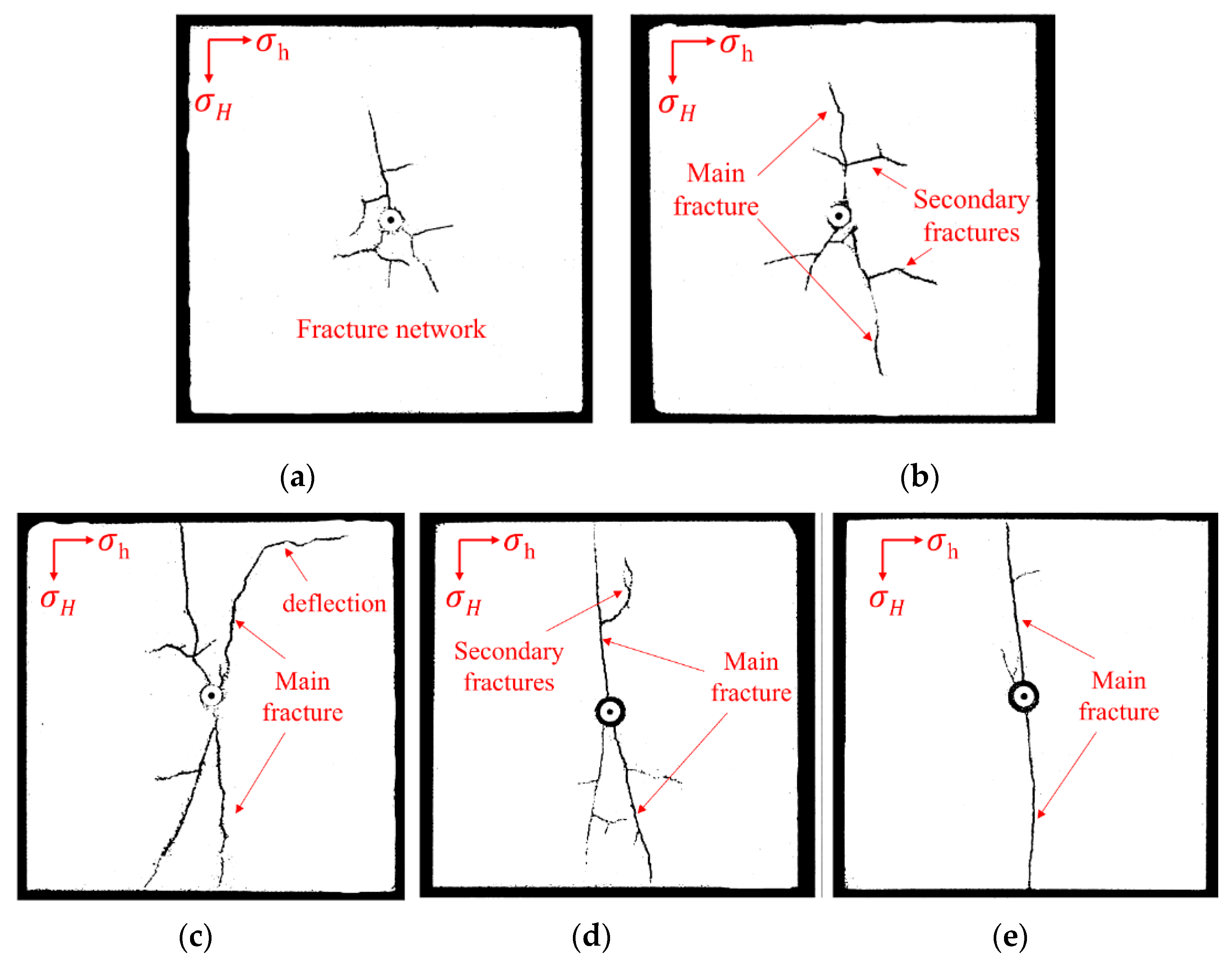
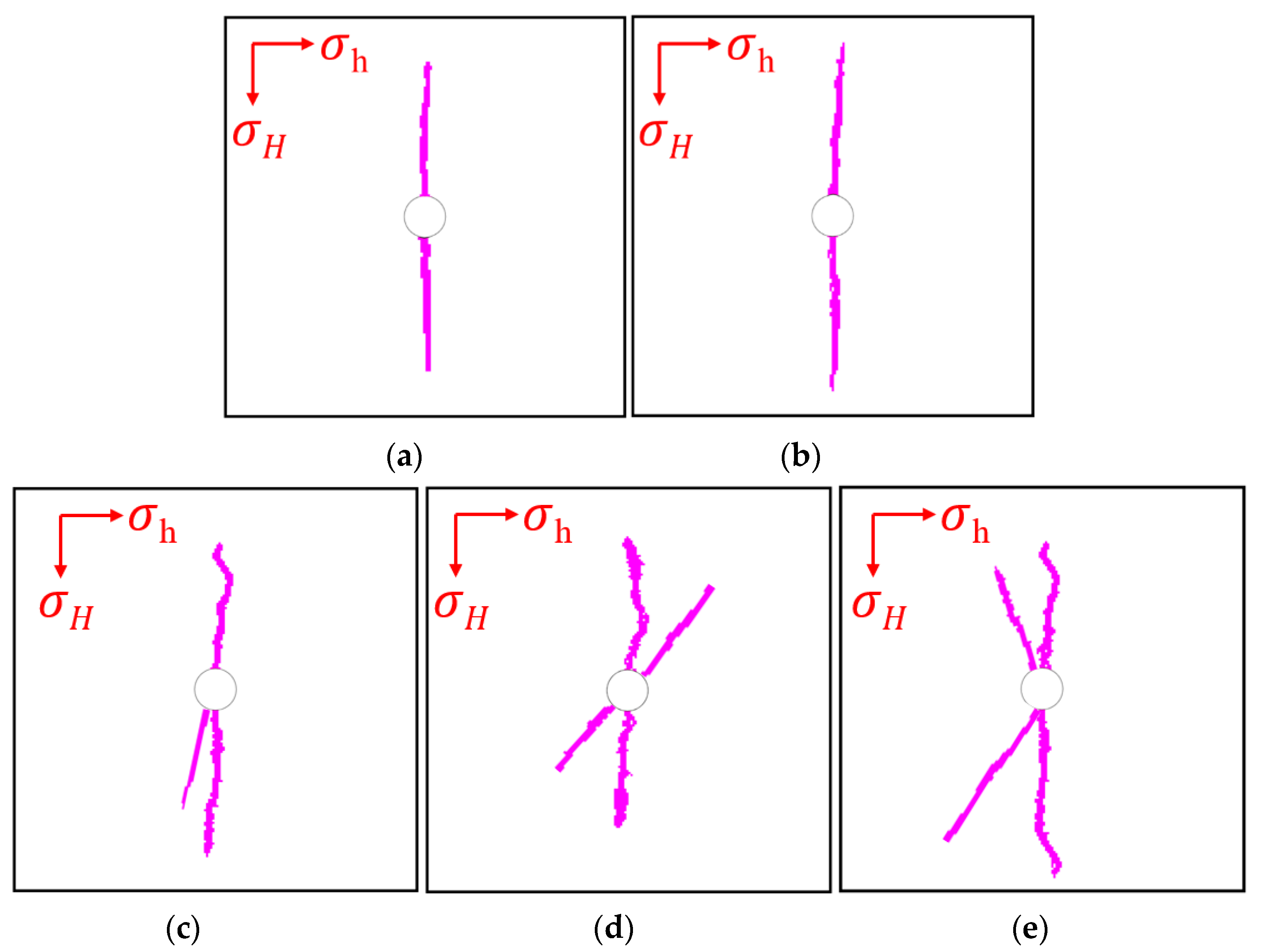
The in situ stress state is the dominant parameter in controlling fracture propagation for fluid-driven fractures. Fracture networks are easily formed when horizontal stress difference is small and a smooth fracture parallel to the maximum horizontal stress direction will be formed when the horizontal stress difference is large. Moreover, the effect of natural fractures and bedding plans may deflect the fracture propagation direction.
(2)
The fracturing fluid with lower viscosity may induce secondary fractures and creates more branches during main fracture propagation. Due to the low-viscosity property, non-aqueous fluid is more likely to penetrate into smaller pore throats in which large viscosity fluid will be excluded in the shale matrix. More branches and secondary fractures may benefit the shale gas production through increasing reservoir permeability.
(3)
The competing effect of fluid viscosity and stress state decides the fracture propagation and morphology. The non-aqueous fluids like liquid carbon dioxide, supercritical carbon dioxide, and nitrogen are promising for working as fracturing fluid by creating more branches and secondary fractures and finally forming the fracture networks. However, economic, safety and filtration quality should be further analyzed before wide utilization of non-aqueous fluid for fracturing in shale reservoirs.

Author Contributions

Conceptualization, Y.J., Z.L. and H.L.; Formal analysis, Y.J.; Investigation, Y.C. and X.Z.; Methodology, Y.J. and Z.L.; Software, J.W.; Writing—original draft, Y.J.; Writing—review and editing, Y.J., Z.L. and H.L. All authors have read and agreed to the published version of the manuscript.

Funding

Funding from open project of Laboratory of Shale Gas Exploration Ministry of Natural Resources (Project No. KLSGE-MLR-201902), National Natural Science Foundation of China (Project No. 51904049), and support plan for science and technology innovation leading talent of Chongqing (No. CSTCCXLJRC201712) are acknowledged.

Conflicts of Interest

The authors declare no conflict of interest.

References

  1. Beckwith, R. Hydraulic fracturing: The fuss, the facts, the Future. J. Pet. Technol. 2010, 62, 34–40. [Google Scholar] [CrossRef]
  2. Sovacool, B.K. Cornucopia or curse? Reviewing the costs and benefits of shale gas hydraulic fracturing (fracking). Renew. Sustain. Energy Rev. 2014, 37, 249–264. [Google Scholar] [CrossRef]
  3. Rivard, C.; Lavoie, D.; Lefebvre, R.; Séjourné, S.; Lamontagne, C.; Duchesne, M. An overview of Canadian shale gas production and environmental concerns. Int. J. Coal Geol. 2014, 126, 64–76. [Google Scholar] [CrossRef]
  4. Mahadevan, J.; Sharma, M.M.; Yortsos, Y.C. Capillary wicking in gas wells. SPE J. 2007, 12, 429–437. [Google Scholar] [CrossRef]
  5. Lu, Y.; Ao, X.; Tang, J.; Jia, Y.; Zhang, X.; Chen, Y. Swelling of shale in supercritical carbon dioxide. J. Nat. Gas Sci. Eng. 2016, 30, 268–275. [Google Scholar] [CrossRef]
  6. Lyu, Q.; Ranjith, P.G.; Long, X.; Kang, Y.; Huang, M. A review of shale swelling by water adsorption. J. Nat. Gas Sci. Eng. 2015, 27, 1421–1431. [Google Scholar] [CrossRef]
  7. Kreipl, M.P.; Kreipl, A.T. Hydraulic fracturing fluids and their environmental impact: Then, today, and tomorrow. Environ. Earth Sci. 2017, 76, 160. [Google Scholar] [CrossRef]
  8. Elsworth, D.; Spiers, C.J.; Niemeijer, A.R. Understanding induced seismicity. Science 2016, 354, 1380–1381. [Google Scholar] [CrossRef]
  9. Ellsworth, W.L. Injection-induced earthquakes. Science 2013, 341, 142–143. [Google Scholar] [CrossRef]
  10. Das, I.; Zoback, M.D. Long-period long-duration seismic events during hydraulic stimulation of shale and tight-gas reservoirs—Part 2: Location and mechanisms. Geophysics 2013, 78, 2–10. [Google Scholar] [CrossRef] [Green Version]
  11. Hou, P.; Gao, F.; Ju, Y.; Liang, X.; Zhang, Z.; Cheng, H.; Gao, Y. Experimental investigation on the failure and acoustic emission characteristics of shale, sandstone and coal under gas fracturing. J. Nat. Gas Sci. Eng. 2016, 35, 211–223. [Google Scholar] [CrossRef]
  12. Chen, Y.; Nagaya, Y.; Ishida, T. Observations of fractures induced by hydraulic fracturing in anisotropic granite. Rock Mech. Rock Eng. 2015, 48, 1455–1461. [Google Scholar] [CrossRef]
  13. Ishida, T.; Chen, Y.; Bennour, Z.; Yamashita, H.; Inui, S.; Nagaya, Y.; Naoi, M.; Chen, Q.; Nakayama, Y.; Nagano, Y.; et al. Features of CO2 fracturing deduced from acoustic emission and microscopy in laboratory experiments. J. Geophys. Res. Solid Earth 2016, 121, 8080–8098. [Google Scholar] [CrossRef] [Green Version]
  14. Wang, L.; Yao, B.; Cha, M.; Alqahtani, N.B.; Patterson, T.W.; Kneafsey, T.J.; Miskimins, J.L.; Yin, X.; Wu, Y.-S. Waterless fracturing technologies for unconventional reservoirs-opportunities for liquid nitrogen. J. Nat. Gas Sci. Eng. 2016, 35, 160–174. [Google Scholar] [CrossRef] [Green Version]
  15. Li, X.; Feng, Z.; Han, G.; Elsworth, D.; Marone, C.; Saffer, D.; Cheon, D.-S. Breakdown pressure and fracture surface morphology of hydraulic fracturing in shale with H2O, CO2 and N2. Geomech. Geophys. Geo Energy Geo Resour. 2016, 2, 63–76. [Google Scholar] [CrossRef] [Green Version]
  16. Hou, P.; Gao, F.; Gao, Y.; Yang, Y.; Cai, C. Changes in breakdown pressure and fracture morphology of sandstone induced by nitrogen gas fracturing with different pore pressure distributions. Int. J. Rock Mech. Min. Sci. 2018, 109, 84–90. [Google Scholar] [CrossRef]
  17. Ghafoori, A.; Shahbazi, K.; Darabi, A.; Soleymanzadeh, A.; Abedini, A. The experimental investigation of nitrogen and carbon dioxide water-alternating-gas injection in a carbonate reservoir. Pet. Sci. Technol. 2012, 30, 1071–1081. [Google Scholar] [CrossRef]
  18. Guo, T.; Zhang, S.; Qu, Z.; Zhou, T.; Xiao, Y.; Gao, J. Experimental study of hydraulic fracturing for shale by stimulated reservoir volume. Fuel 2014, 128, 373–380. [Google Scholar] [CrossRef]
  19. Gan, Q.; Elsworth, D.; Alpern, J.S.; Marone, C.; Connolly, P. Breakdown pressures due to infiltration and exclusion in finite length boreholes. J. Pet. Sci. Eng. 2015, 127, 329–337. [Google Scholar] [CrossRef]
  20. Ha, S.J.; Choo, J.; Yun, T.S. Liquid CO2 fracturing: Effect of fluid permeation on the breakdown pressure and cracking behavior. Rock Mech. Rock Eng. 2018, 51, 3407–3420. [Google Scholar] [CrossRef]
  21. Peng, P.; Yang, J.; Wang, Y.; Wang, S.; Feng, G. Numerical analysis of the effect of natural microcracks on the supercritical CO2 fracturing crack network of shale rock based on bonded particle models. Int. J. Numer. Anal. Methods Geomech. 2017, 41, 1992–2013. [Google Scholar] [CrossRef]
  22. Wang, J.; Elsworth, D.; Wu, Y.; Liu, J.; Zhu, W.; Liu, Y. The influence of fracturing fluids on fracturing processes: A comparison between water, oil and SC-CO2. Rock Mech. Rock Eng. 2017, 51, 299–313. [Google Scholar] [CrossRef]
  23. Liu, L.; Zhu, W.; Wei, C.; Elsworth, D.; Wang, J. Microcrack-based geomechanical modeling of rock-gas interaction during supercritical CO2 fracturing. J. Pet. Sci. Eng. 2018, 164, 91–102. [Google Scholar] [CrossRef]
  24. Middleton, R.S.; Carey, J.W.; Currier, R.P.; Hyman, J.D.; Kang, Q.; Karra, S.; Jiménez-Martínez, J.; Porter, M.L.; Viswanathan, H.S. Shale gas and non-aqueous fracturing fluids: Opportunities and challenges for supercritical CO2. Appl. Energy 2015, 147, 500–509. [Google Scholar] [CrossRef] [Green Version]
  25. Jia, Y.; Lu, Y.; Elsworth, D.; Fang, Y.; Tang, J. Surface characteristics and permeability enhancement of shale fractures due to water and supercritical carbon dioxide fracturing. J. Pet. Sci. Eng. 2018, 165, 284–297. [Google Scholar] [CrossRef]
  26. Zhang, X.; Lu, Y.; Tang, J.; Zhou, Z.; Liao, Y. Experimental study on fracture initiation and propagation in shale using supercritical carbon dioxide fracturing. Fuel 2016, 190, 370–378. [Google Scholar] [CrossRef]
  27. Middleton, R.S.; Gupta, R.; Hyman, J.D.; Viswanathan, H.S. The shale gas revolution: Barriers, sustainability, and emerging opportunities. Appl. Energy 2017, 199, 88–95. [Google Scholar] [CrossRef]
  28. Detournay, E.; Carbonell, R. Fracture-mechanics analysis of the breakdown process in mini fracture or leakoff test. SPE Prod. Facil. 1997, 12, 29–31. [Google Scholar] [CrossRef]
  29. Detournay, E. Mechanics of hydraulic fractures. Annu. Rev. Fluid Mech. 2016, 48, 311–339. [Google Scholar] [CrossRef]
  30. Savitski, A.A.; Detournay, E. Propagation of a penny-shaped fluid-driven fracture in an impermeable rock: Asymptotic solutions. Int. J. Solids Struct. 2002, 39, 6311–6337. [Google Scholar] [CrossRef]
  31. Tan, P.; Jin, Y.; Han, K.; Hou, B.; Chen, M.; Guo, X.; Gao, J. Analysis of hydraulic fracture initiation and vertical propagation behavior in laminated shale formation. Fuel 2017, 206, 482–493. [Google Scholar] [CrossRef]
  32. Kresse, O.; Weng, X.; Gu, H.; Wu, R. Numerical modeling of hydraulic fractures interaction in complex naturally fractured formations. Rock Mech. Rock Eng. 2013, 46, 555–568. [Google Scholar] [CrossRef]
  33. Zhu, W.C.; Tang, C.A. Micromechanical model for simulating the fracture process of rock. Rock Mech. Rock Eng. 2004, 37, 25–56. [Google Scholar] [CrossRef]
  34. Tang, C. Numerical simulation of progressive rock failure and associated seismicity. Int. J. Rock Mech. Min. Sci. 1997, 34, 249–261. [Google Scholar] [CrossRef]
Figure 1. Schematic diagram showing apparatus for fracturing tests. The temperature of the whole system is 60 °C to make CO2 into the supercritical state before injection into shale samples.
Minerals 10 00428 g001
Figure 2. (a) Samples used in fracturing tests. The sample dimension is 200 mm × 200 mm × 200 mm cubic with a central borehole which length is 110 mm; (b) illustration of computed tomography (CT) scan plane. The scanning planes are perpendicular to the borehole direction.
Minerals 10 00428 g002
Figure 3. The relationship between fluid pressure and the elapsed time for all seven fracturing experiments.
Minerals 10 00428 g003
Figure 4. CT scanning images with various fluid under the same stress state. (a) water; (b) liquid carbon dioxide; (c) supercritical carbon dioxide. Supercritical carbon dioxide creates fractures with a complex fracture pattern, which includes fractures and secondary fractures.
Minerals 10 00428 g004
Figure 5. CT scanning images with supercritical carbon dioxide under various stress states after grayscale manipulation. (a) σH-σh = 0; (b) σH-σh = 1 MPa; (c) σH-σh = 2 MPa; (d) σH-σh = 3 MPa; (e) σH-σh = 4 MPa. With the decrease of stress difference, a fracture network with more secondary fractures is more easily induced.
Minerals 10 00428 g005
Figure 6. Maximum tensile stress criteria and the Coulomb shear failure criteria used in the model. The red and blue Mohr circles represent stress states where tensile failure and shear failure are imminent.
Minerals 10 00428 g006
Figure 7. The geometry of the model which is used in fracturing propagation type numerical simulation works.
Minerals 10 00428 g007
Figure 8. Numerical simulation results when injecting various fluids. (a) Viscous oil; (b) water; (c) liquid carbon dioxide; (d) supercritical carbon dioxide; (e) nitrogen.
Minerals 10 00428 g008
Figure 9. Numerical simulation results when injecting supercritical carbon dioxide under various stress states. (a) σH-σh = 0; (b) σH-σh = 1 MPa; (c) σH-σh = 2 MPa; (d) σH-σh = 3 MPa; (e) σH-σh = 4 MPa.
Minerals 10 00428 g009
Figure 10. The comparison between experimental observations and numerical simulation results when injecting various fluids. (a) water; (b) liquid carbon dioxide; (c) supercritical carbon dioxide.
Minerals 10 00428 g010
Figure 11. The comparison between experimental observations and numerical simulation results when injecting supercritical carbon dioxide under various stress states. (a) σH-σh = 0; (b) σH-σh = 1 MPa; (c) σH-σh = 2 MPa; (d) σH-σh = 3 MPa; (e) σH-σh = 4 MPa.
Minerals 10 00428 g011
Figure 12. The evolution of fluid viscosity against the pressure of fluids.
Minerals 10 00428 g012
Figure 13. Summary of fracture tortuosity from experimental observations and simulation results.
Minerals 10 00428 g013
Figure 14. Illustration of fracture propagation type with different viscosity fluid. (a) Low-viscosity fluid-driven fracture propagation. (b) High-viscosity fluid-driven fracture propagation. Low-viscosity fluid more easily penetrates smaller pore throats and creates secondary fracture or fractures with larger tortuosity.
Minerals 10 00428 g014
Table 1. Petrophysical properties of the Longmaxi shale.
ParametersValuesUnits
Tensile Strength13.5MPa
Compressive Strength136.0MPa
Young’s Modulus25.0GPa
Porosity3.91%-
Bulk Modulus16.70GPa
Poisson’s ratio0.25-
Total Organic Carbon (TOC)0.55–4.41%-
Table 2. Mineral compositions of the Longmaxi shale.
MineralsPercentage (%)
Quartz53.50
Calcite20.30
Illite9.80
Dolomite8.70
Pyrite3.60
Plagioclase3.10
K-feldspar1.00
Table 3. Experimental conditions and results for fracturing tests.
Test NumberFracturing FluidStress State (σV/σH/σh)Horizontal Stress Difference (MPa)Temperature (°C)Breakdown Pressure (MPa)Injection Time (s)Total Injection Volume (mL)
1H2O12/10/822529.2514271
2L-CO212/10/822518.70552276
3Sc-CO212/10/826014.11440220
4Sc-CO212/10/1006016.21469234.5
5Sc-CO212/9/816015.22452226
6Sc-CO212/9/636013.33435217.5
7Sc-CO212/10/646012.89411205.5
Table 4. Parameters used in the model.
ParametersValuesUnits
Homogeneity index/m5.0Dimensionless
Elastic modulus/E25.0GPa
Uniaxial compressive strength/fc140MPa
Uniaxial tensile strength/ft11MPa
Poisson ratio/υ0.25Dimensionless
Residual strength coefficient/λ0.1Dimensionless
Ultimate strain coefficient/η5.0Dimensionless
Initial porosity/Φ00.01Dimensionless
Initial permeability/k01.0 × 10−21m2
Initial pore pressure/p00.1MPa

