References [
33,
34] described efforts to describe objectively the quality of piano tones, as understood by musicians, and they tried to find synthetic tones that would be considered to be better than real piano tones. Casey showed that a two-layer feed-forward model can perform inverse mapping for a simple physical model of a string [
35]. References [
36,
37] showed the numerical approach and the underlying physical model can be improved to simulate the motion of a piano string with a high degree of realism. This work develops a model of instruments as follows. First, a discrete Fourier transform (DFT) is utilized to transform the sampled sound data of an instrument from the time domain to the frequency domain. When a real instrumental pitch is recorded, analog acoustic is digitalized with being sampled automatically by a computer. Then the DFT could be adopted to classify and decompose the composition of the frequencies of a single pitch. Second, use the frequency domain function and the sound of an instrument is described as a pattern, which is generated using DFT and the inverse DFT, which are used to analyze sampled data using computers.
Section 2.1 is the fundamental of the methodology, while
Section 2.2 is the proposed scheme.
2.1. Fundamentals
This section discusses why musical instruments produce such beautiful music. Harmonics will be introduced. Fourier transformations are based on the fact that a function in the time domain can be represented as a summation of cosine functions. Consider the periodic square wave, plotted in
Figure 2. The signal
can be represented by Equation (1) [
38]:
The frequency
is the fundamental frequency. As
k increases, the coefficient of the cosine function,
, decreases. Hence, only the coefficients for
and other low values are important. The cosine function for
is known as the second harmonic; that for
is the third harmonic, and so on. The sound of any musical note that is produced by a musical instrument contains the fundamental frequency and a few harmonics.
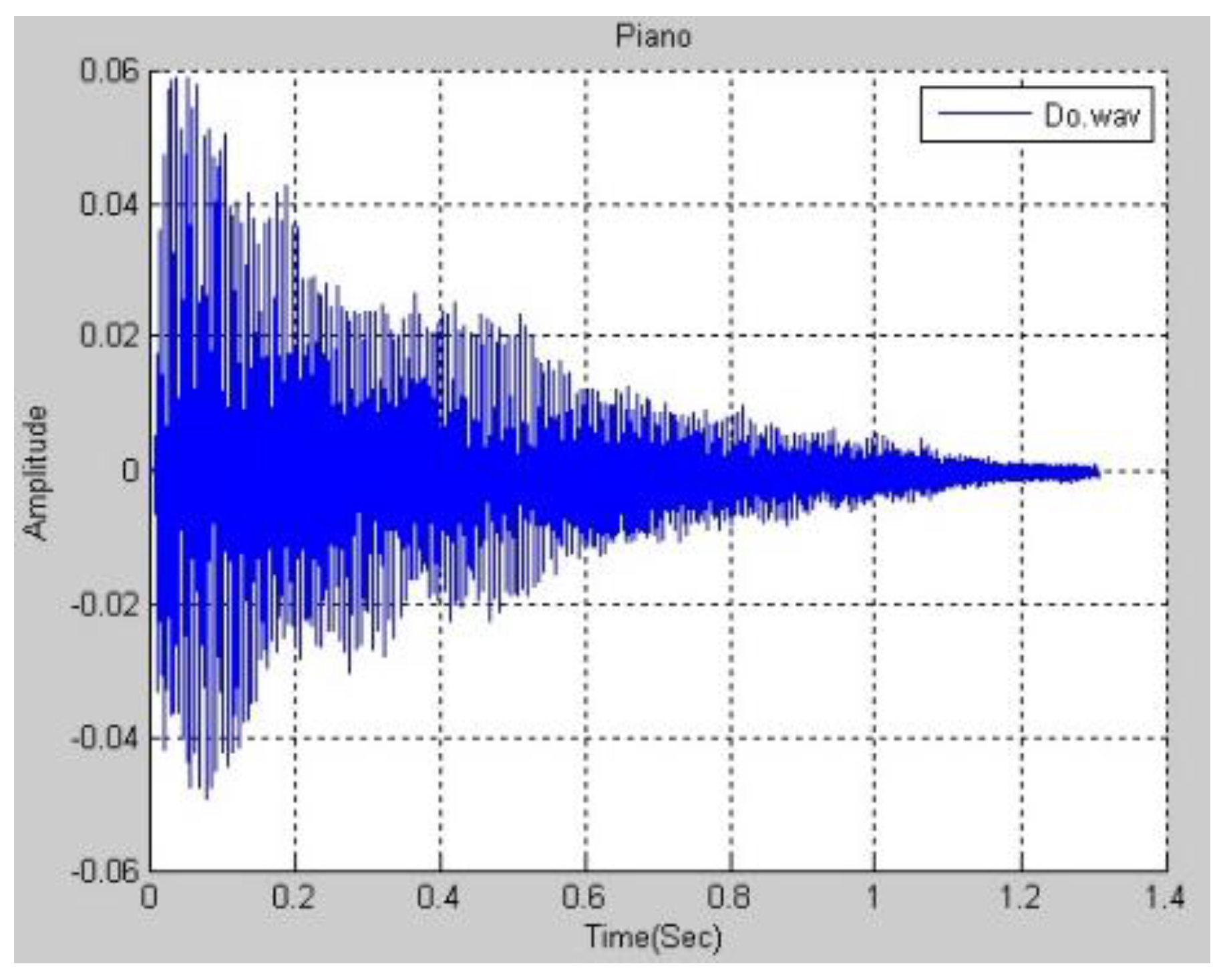
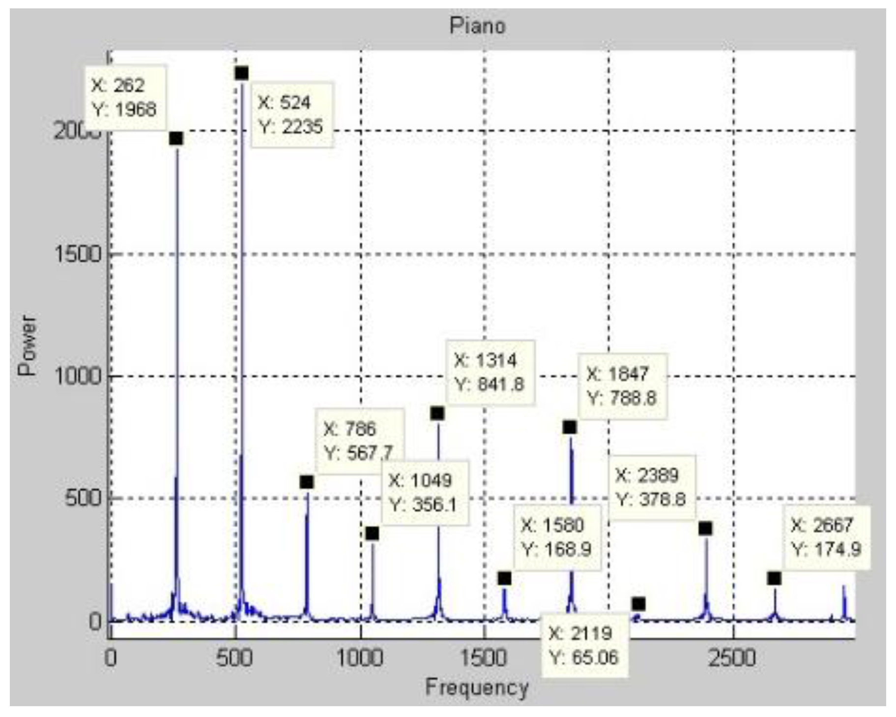
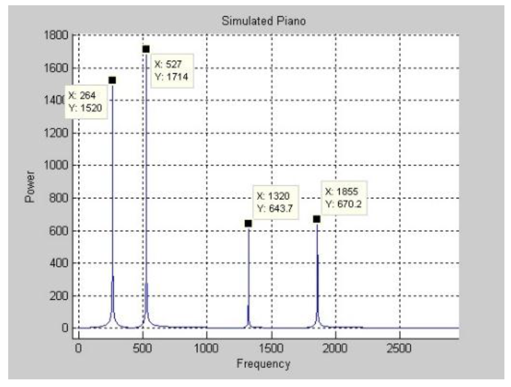
Figure 3 plots the function of a real piano’s Middle C in the time domain. The DFT is applied to the function in
Figure 3 to obtain the frequency spectrum in
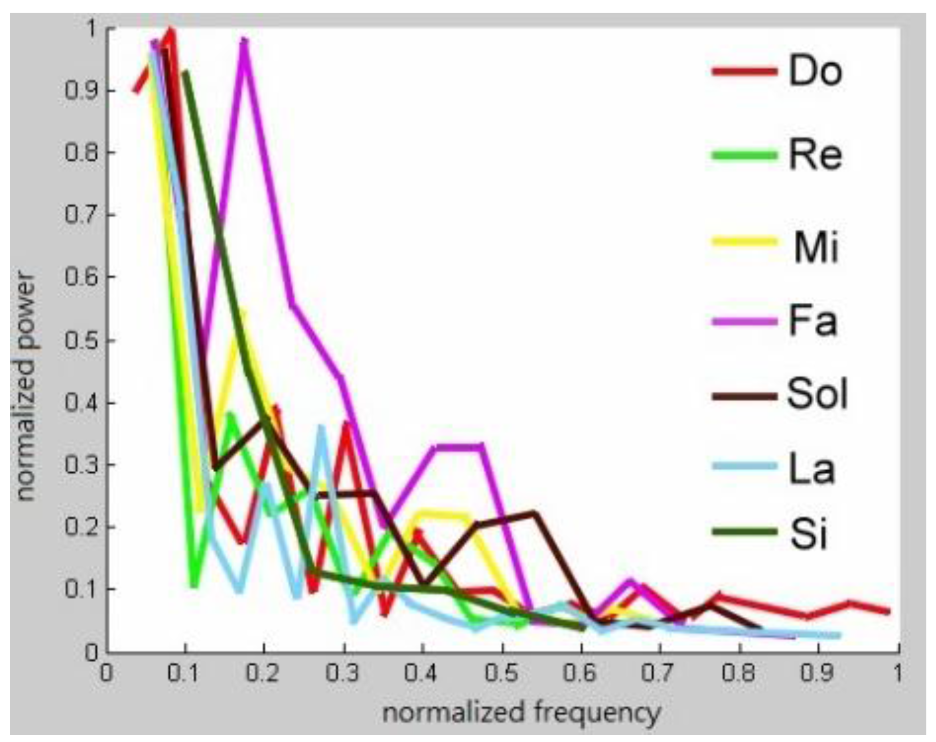
Figure 4. Only a few of the magnitudes are marked because space is limited. After the frequency spectrum of Middle C on a real piano was obtained, the frequency spectra of all of the pitches that are produced in the middle region of a piano are found.
Figure 5 displays these spectra.
A real music instrument produces different pitches with different frequency patterns. Consider a randomly chosen musical instrument, such as a piano and the playing of any note on it. Perform a DFT on the note. The
k frequencies with the largest magnitudes are selected. Denote these frequencies as
, where
, with magnitudes
,
. Calculate
for
. Now suppose that the goal is to generate a frequency pattern for Middle C. The fundamental frequency of Middle C is known to be 262 Hz. Denote this frequency as
. The Middle C that is generated by a real piano has frequencies
with magnitudes
, respectively, and the inverse DFT generates the sound from these frequencies. Of course, musical sounds that are generated in this way are not expected to be the same as those produced by a piano. However, as demonstrated by the following experiment, they will be piano-like if
is sufficiently large. The
k frequencies with the largest magnitudes are selected using the prune and search method [
39].
The following experiments involve synthesized pitches. Let
so the ten frequencies with the largest magnitudes are obtained. The magnitudes
and respective multiples
are found and shown in
Table 1. Middle C on a piano has frequencies (
, 1.0038
, …, 7.0843
) with respect magnitudes (0.2635, 0.7042, …, 0.2402). Let
, yielding frequencies of (262, 263, …, 1856 Hz).
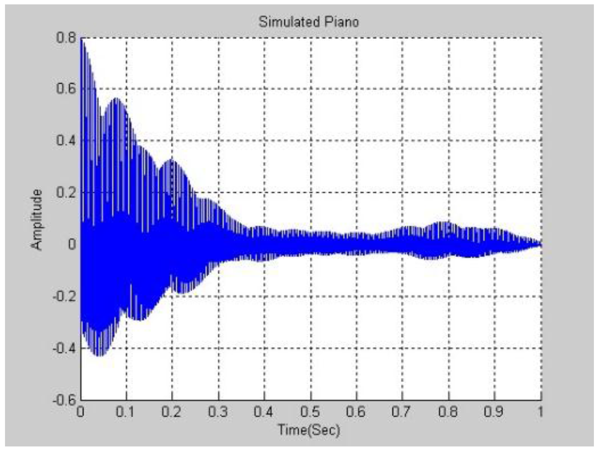
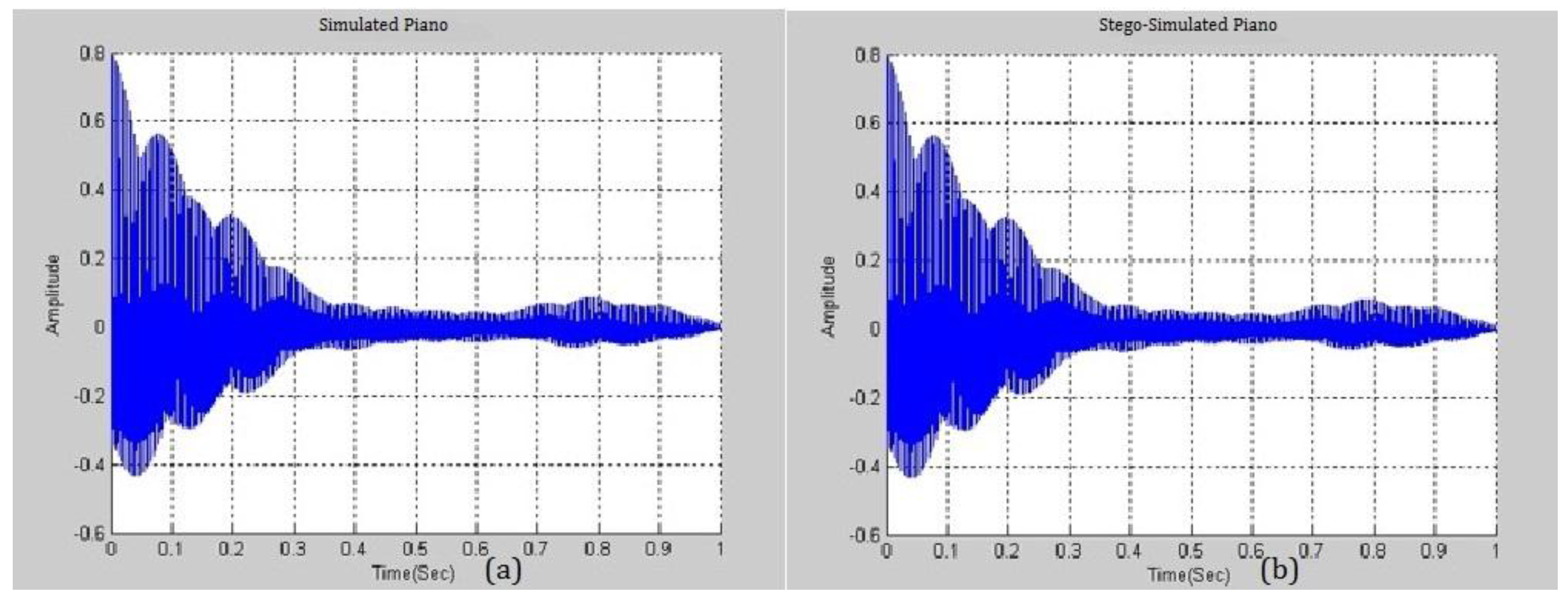
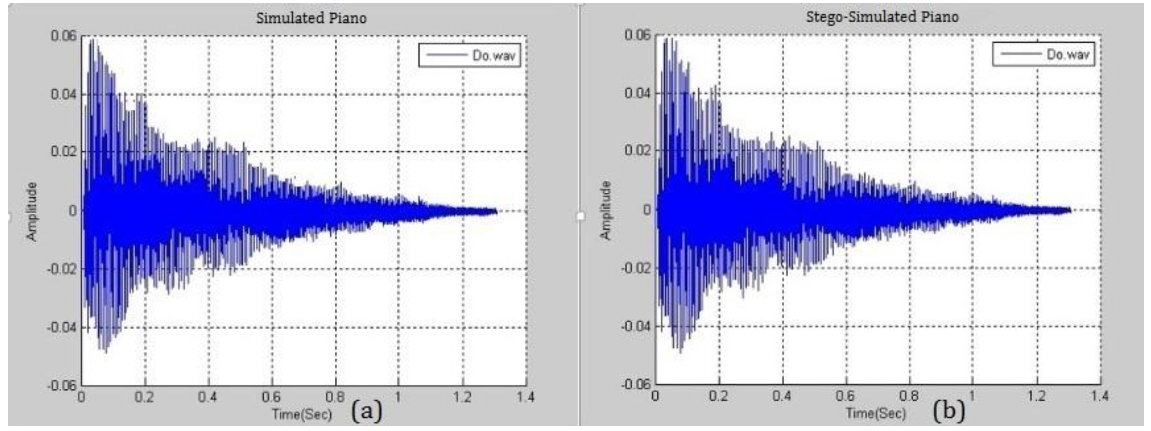
Figure 6 and
Figure 7 plot the experimental results in the frequency and time domains. Comparing
Figure 3 and
Figure 7, the waves are not similar.
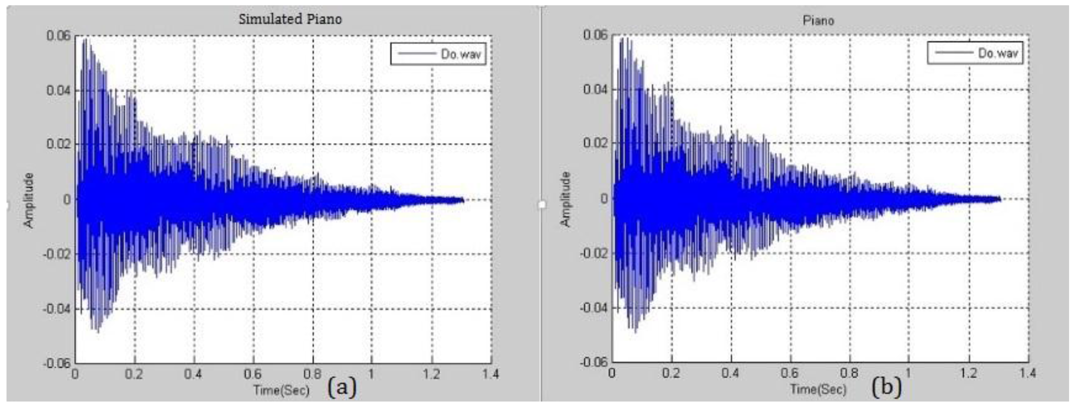
Figure 8 presents the similarity between a simulated piano note with
and a real piano note. The difference between them is negligible and this fact will be exploited in the following section. A higher
yields a smaller distortion and the higher ability to embed more secrets. Various pitches from different musical instruments were simulated and analyzed.
2.2. Data Hiding Scheme
The proposed data-hiding scheme involves the following steps. First, choose an instrumental pitch
P to be the reference pitch. With reference to the preceding sections, all of the required parameters can be obtained. These include the magnitudes
and the main frequencies
. The number of
terms is
k and the number of
terms is
k because the system is used only to generate the main
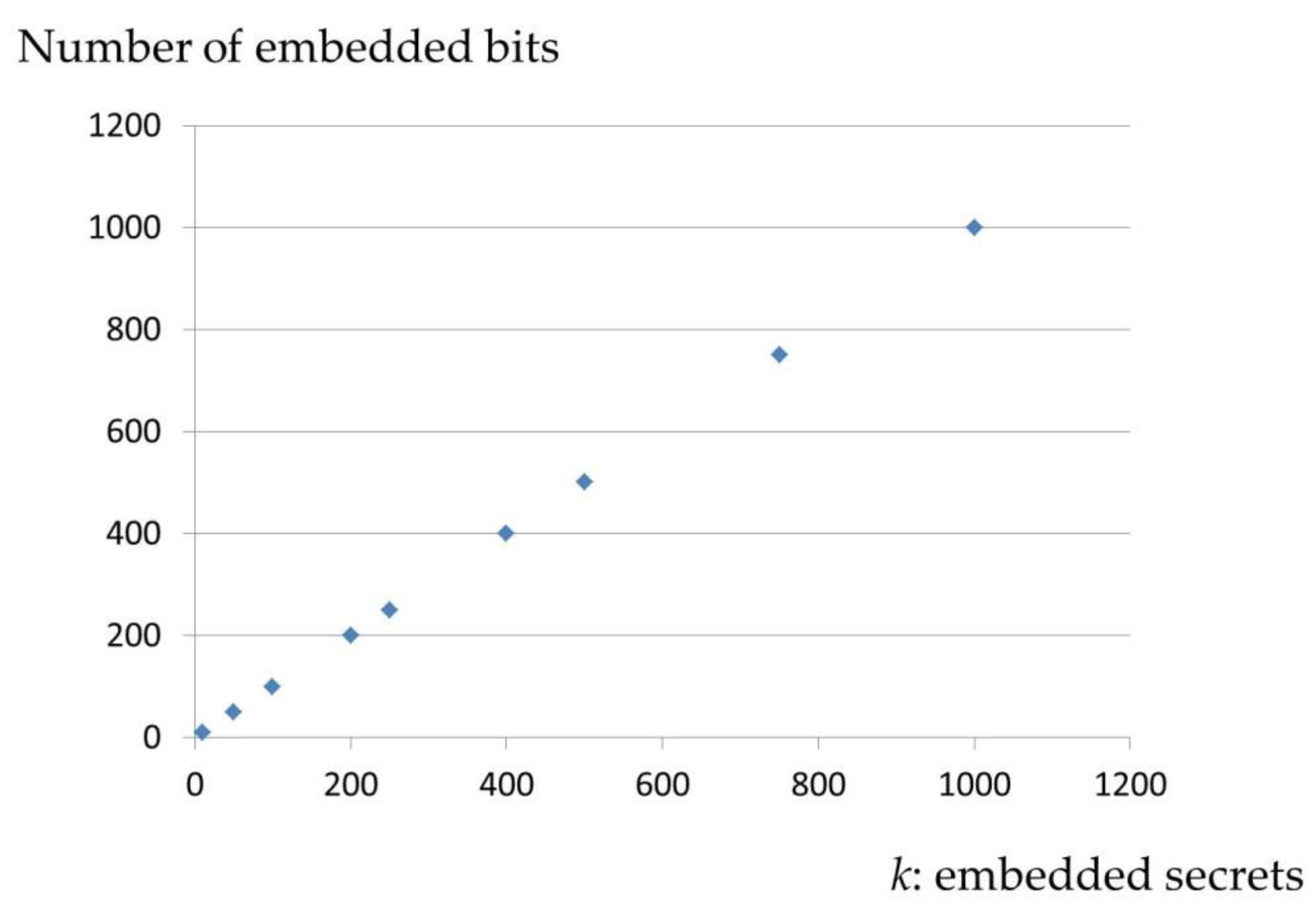
k frequencies of the signals. Next, suppose that the length of the secret bit stream
is also
k. If
, then
is increased to
; the same operation is applied to
.
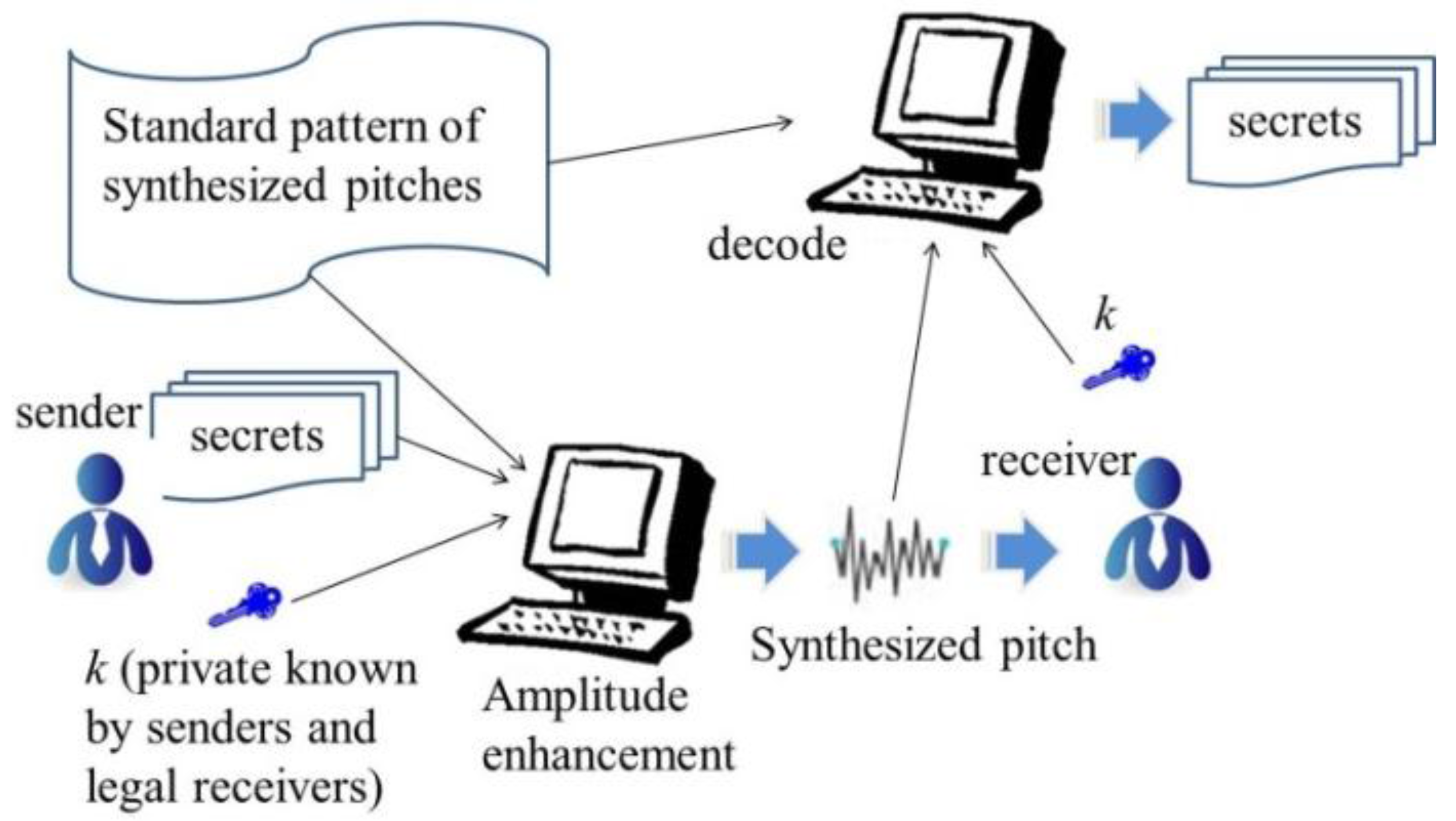
Figure 9 is the overview of the scheme. The sender uses the standard pattern of synthesized pitches and
k to encode the secrets to generate a synthesized pitch using amplitude enhancement. A legal receiver uses the standard pattern of synthesized pitches and
k to decode the secret.
Algorithm 1 is the simple encoding procedure. Algorithm 2 is the decoding procedure.
| Algorithm 1 Encoding Procedure |
| Input: | secret bit stream and reference instrumental pitch P |
| Output: | a stego-synthesized pitch |
| Step 1: | find and by referencing P |
| Step 2: | for all , obtain as follows; |
| | if () |
| | set |
| | else |
| | set |
| Step 3: | use and to create a pitch p |
| Step 4: | return p |
| Algorithm 2 Encoding Procedure |
| Input: | length of secret k, reference pitch P and received pitch p |
| Output: | secret bit stream |
| Step 1: | use standard pattern in Section 2.1 to obtain of P |
| Step 2: | use standard pattern in Section 2.1 to obtain of p |
| Step 3: | for each and , decode secret bit as follows. |
| | if () |
| | set |
| | else |
| | set |
| Step 4: | concatenate to form a bit stream B |
| Step 5: | return B |
The value
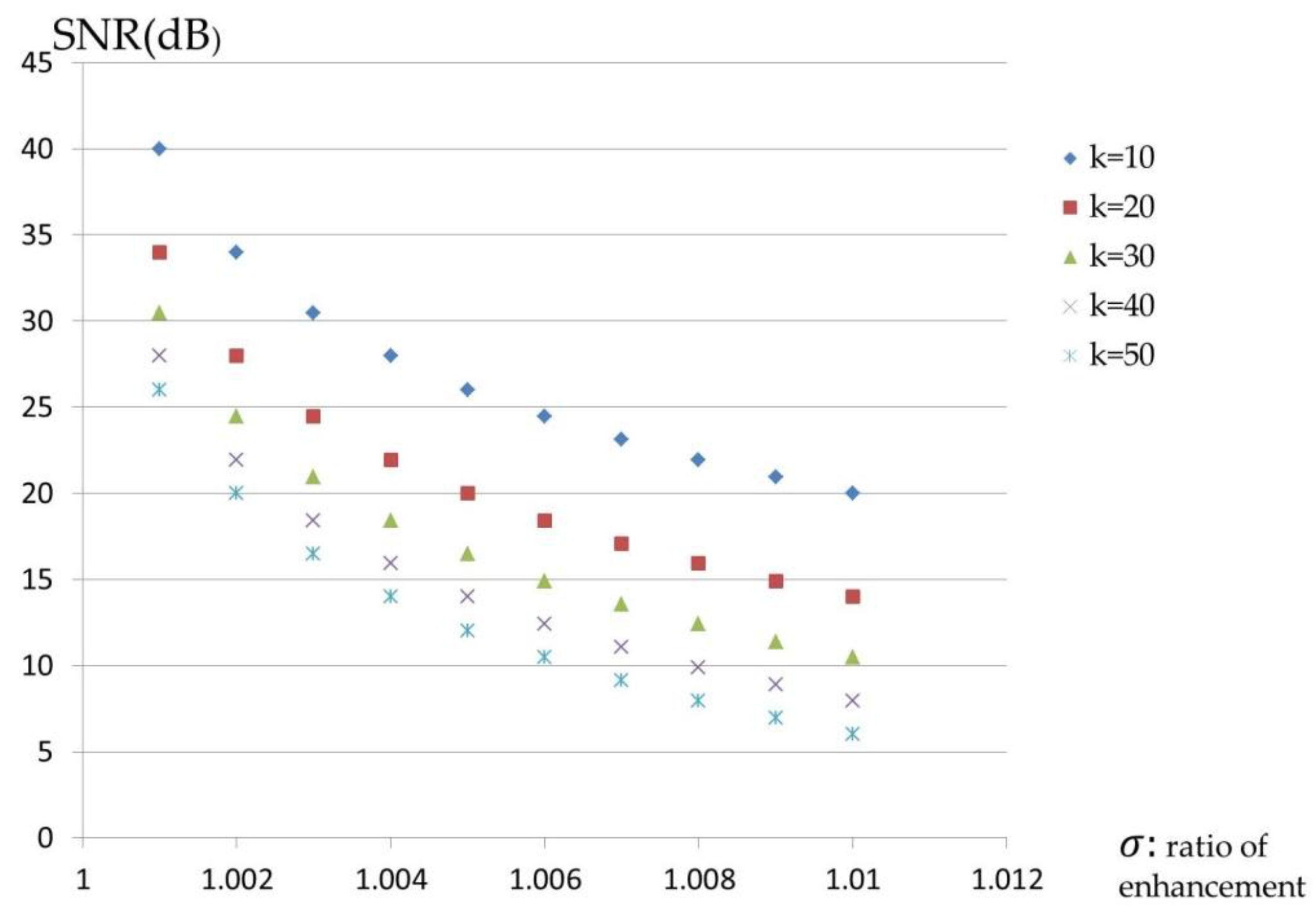
shall be too small to be perceived by the human ear. Consider, for example,
Table 2: hiding bit stream 1001101101 in the synthesized pitch yields the enhanced magnitudes, which are shown in the first table.
Legitimate receivers obtain the reference instrumental pitch P, the length of the secret k and the method of generation of the synthesized pitches. The decoding procedure is as follows. First, identify the main frequencies that correspond to the k largest magnitudes from P and the received pitch p. The frequencies of the former are denoted as and those of the latter are denoted as . The magnitudes of all main frequencies are obtained as and . Each is compared with the corresponding ; for Algorithm 4, Step 3, if , then the secret bit ; otherwise, . Finally, all s are concatenated and the secret bit stream can be produced.
While the synthesis of musical pitches and the data-hiding scheme are public, the above algorithms can be designed more secure by including a parameter
R, which is the real order of
and
during the data embedding procedure.
R is generated using a random number generator and the seed of the generator is obtained by legal receivers. The formal definition of
R is
where all
have different values. An example follows. Consider
;
Table 3 is obtained after the complex version of the data embedding scheme is implemented. The red numbers indicate hidden secret “1” bits. Evidently, the positions of the secret bits differ from those in the second table. Algorithms 3 and 4 describe the complex version of the proposed scheme.
| Algorithm 3 Encoding Procedure |
| Input: | secret bit stream , secret order R and reference instrumental pitch P |
| Output: | a stego-synthesized pitch |
| Step 1: | find and by referencing P |
| Step 2: | for all , obtain as follows. |
| | if () |
| | set |
| | else |
| | set |
| Step 3: | use and to create a pitch p |
| Step 4: | return p |
Unlike in the first version, receivers no longer need the value of
k but only the secret order
R or random seed.
| Algorithm 4 Encoding Procedure |
| Input: | secret order R, reference pitch P and received pitch p |
| Output: | secret bit stream |
| Step 1: | use standard pattern in Section 2.1 to obtain of P |
| Step 2: | use standard pattern in Section 2.1 to obtain of p |
| Step 3: | for all , decode secret bit with reference to the following condition: |
| | if () |
| | set |
| | else |
| | set |
| Step 4: | concatenate to form a bit stream B |
| Step 5: | return B |
The above two proposed embedding schemes focus on enhancing amplitudes when secret “1” bits are embedded. However, it shall be considered that the enhancement will be too large if there are too many “1” bits. A strengthened version is presented here called alternating current (AC) algorithm. The main idea of AC algorithm is to reduce a large enhancement caused by embedding secret “1” bits. The embedding scheme goes on alternatively enhancing each amplitude by multiply
and
. For the example in
Table 3, the parameters are modified as listed in
Table 4 by adopting AC algorithm. The numbers of the even positions (9, 4, 8) of embedding secret “1” bits are modified by multiplying
. Algorithms 5 and 6 describe the embedding and extracting procedures of the AC algorithm, respectively.
| Algorithm 5 Encoding Procedure |
| Input: | secret bit stream , secret order R and reference instrumental pitch P |
| Output: | a stego-synthesized pitch |
| Step 1: | find and by referencing P |
| Step 2: | initialize AC = 0 |
| Step 3: | for all , obtain as follows. |
| | if () |
| | if(AC = 0) |
| | set |
| | set AC = 1 |
| | else |
| | set |
| | set AC = 0 |
| | else |
| | set |
| Step 4: | use and to create a pitch p |
| Step 5: | return p |
| Algorithm 6 Encoding Procedure |
| Input: | secret order R, reference pitch P and received pitch p |
| Output: | secret bit stream |
| Step 1: | use standard pattern in Section 2.1 to obtain of P |
| Step 2: | use standard pattern in Section 2.1 to obtain of p |
| Step 3: | for all , decode secret bit with reference to the following condition: |
| | if () |
| | set |
| | else |
| | set |
| Step 4: | concatenate to form a bit stream B |
| Step 5: | return B |
It shall be proven that even if the proposed steganographic scheme is applied twice, it is still able to get the embedded secrets. A simple proof is given as follows. The basic idea of this presented research work is the enhancement of amplitudes if embeds a secret “1” bits. Applying the embedding procedure twice makes the enhanced amplitudes multiply of again, that is, will be or but not or . When legal receivers apply the decoding procedure, the main strategy is to compare the enhanced amplitudes to the original amplitudes of the standard patterns. The are only three possible values of : , , and . Apparently, the comparisons work and are able to obtain the embedded secrets.
