Abstract
Magnetization dynamics symmetry plays important roles in magnetization switching. Here we study magnetic field and spin torque induced magnetization switching. Spin moment transferring from polarized itinerant electrons to local magnetization provides a magnetization switching mechanism without using external magnetic field. Besides its importance in fundamental magnetization switching dynamics, spin torque magnetization switching has great application potential for future nanoscale magnetoelectronic devices. The paper explores magnetization dynamics symmetry effects on spin torque induced magnetization switching, and its interactions with random fluctuations. We will illustrate the consequences of magnetization dynamics symmetry on the critical switching current magnitude and the thermal stability energy of spin torque induced magnetization switching, which are the two most important design criteria for nanoscale spin torque magnetic devices. The concept of Logarithmic magnetization susceptibility is used to extract symmetry and damping information on spin torque induced nonlinear magnetization dynamic processes, and provides paths to control spin torque induced switching in a fluctuating environment.
1. Introduction
Magnetization switching is a fundamental physics problem that has important practical implications. Achieving desired magnetization switching behavior is the first requirement for utilizing magnetic information. For magnetic devices, writability means the ability to switch magnetization from one equilibrium state to the other equilibrium state. Readability means the magnetization equilibrium state is stable under disturbances, such as random thermal fluctuation, disturbing magnetic field and polarized current excitations. Understanding and manipulating magnetization switching is a challenging issue because magnetization switching is a nonlinear and non-equilibrium process involving large angle magnetization motion due to interactions of the magnetic system with other physical systems at room temperature.
Hidden in these complex magnetization dynamics are switching behaviors that are of interest to a scientist working on magnetism and an engineer working on device design. Over years, I was fascinated by how these switching behaviors can be revealed through magnetization dynamics symmetry. In this paper I will explore magnetization dynamics symmetry effects on magnetization switching. The focus is on spin torque induced magnetization switching [1,2] and its comparison to “more traditional” magnetic field induced switching. However, I believe the approaches developed here can be pursued fruitfully in other “more exotic” magnetization switching mechanisms, such as all electric field magnetization switching [3] and all optical magnetization switching [4].
Magnetization switching refers to magnetization motion from one equilibrium state to another equilibrium state. The magnetization equilibrium state is determined by magnetic energy minimization with respect to the magnetization vector: . The derivative of magnetic energy to magnetization vector gives a restoring force called effective field . For magnetization motion under a constant magnetic field , the effective field is the magnetic field and magnetic energy is Zeeman energy: .
Additional energy terms in a magnetic system include exchange energy and anisotropy energy. Exchange energy brings magnetization order in ferromagnetic material. For a spatially distributed magnetization system (where i denotes spatial position), exchange energy prefers to order neighboring magnetization to the same direction: , where denotes nearest neighboring positions. Magnetization magnitude at individual spatial location is conserved ( = constant). As nano-scale magnetic device scales down, magnetization reversal can be well approximated by the coherent switching mode, where due to exchange ordering effects. In this manuscript, we study coherent magnetization switching with element magnetization described by a magnetization vector with constant magnitude: . Exchange energy does not explicitly enter coherent magnetization switching formalism.
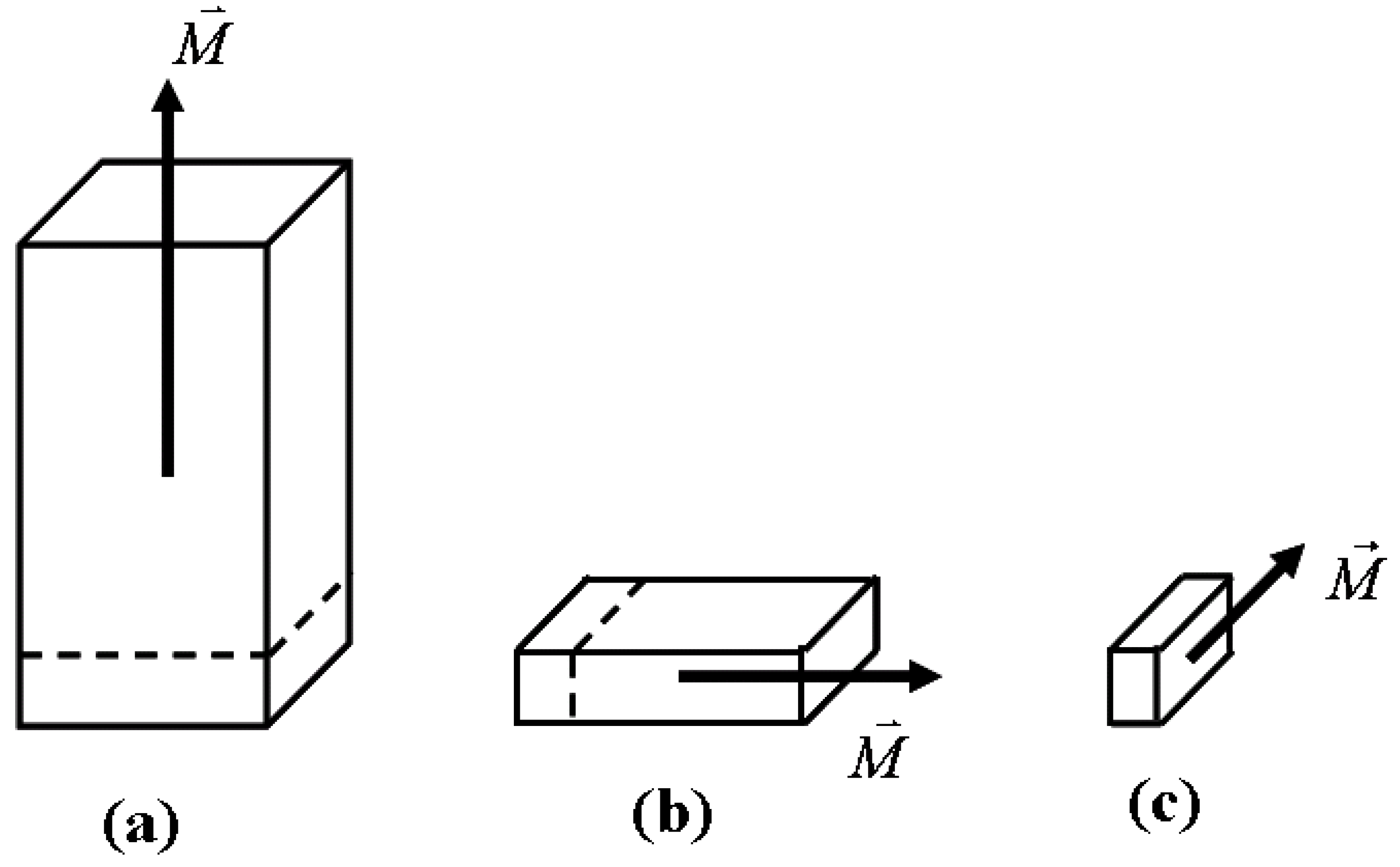
When the physical property of a device has a spatial direction preference, that property is called anisotropy. The preference for the magnetization to point in a particular direction is the result of magnetic anisotropy energy. There are two types of anisotropy energy. The first one is the crystal anisotropy energy from magnetic material crystal structure. The second one is the shape anisotropy energy. The origin of shape anisotropy comes from magnetic dipole interaction (or magnetostatic interaction). The basic property of magnetostatic interaction is the avoidance of surface magnetic charge accumulation. Figure 1 illustrates shape anisotropy (or demagnetization anisotropy). Starting with a cubic element with magnetization orientation in the vertical direction, two cuts change the element shape to a thin film and an elongated needle. The magnetization direction changes in the process as a result of minimizing shape anisotropy energy. The minimization of shape anisotropy is the same as avoiding surface magnetic charge accumulation. Here we assume the material crystal anisotropy is much smaller than the shape anisotropy and the magnetization direction is determined by shape anisotropy. For magnetic material with much stronger crystal anisotropy, the magnetization direction follows the direction of the crystal anisotropy. For example, in the thin film structure Figure 1(b), if there is huge perpendicular crystal anisotropy, the equilibrium magnetization points in the vertical direction against the thin film plane demagnetization factor. This structure is called perpendicular thin film structure.

Figure 1.
Shape anisotropy (or demagnetization factor) effects on magnetization equilibrium states. Starting with a cubic element with magnetization orientation in the vertical direction, two cuts change the element shape to a thin film and an elongated needle. The magnetization direction changes in the process as a result of minimizing shape anisotropy energy. The minimization of shape anisotropy is the same as avoiding surface magnetic charge accumulation.
The magnetic anisotropy energy can be written in a general form:
where is the magnetization saturation, is the magnetic element volume and is the normalized magnetization. are element anisotropy factors (or demagnetization factors) including both shape anisotropy and crystal anisotropy.
Spin torque induced magnetization switching involves a structure of two ferromagnetic layers sandwiching an insulating barrier. The magnetization direction of one ferromagnetic layer (reference layer) is fixed by coupling to a pinned magnetization layer, while the magnetization direction of the other ferromagnetic layer (free layer) can be changed. To switch the free layer magnetization to the same direction as the reference layer magnetization, an electric current is passed from the reference layer to the free layer. The injected current electrons have spins pointing to the same and the opposite directions of the reference layer magnetization. After passing through the reference layer, the electrons have a preferred spin orientation direction pointing to the same direction as the reference layer magnetization. This is because most of the electrons with spin pointing to the opposite direction of the reference layer magnetization are reflected back due to interaction between itinerant electron spin and reference layer local magnetization. The polarized current electrons, with a net spin moment in the same direction as the reference layer magnetization, will switch the free layer magnetization to the same direction as the reference layer magnetization. In order to switch the free layer magnetization to the opposite direction of the reference layer magnetization, electron current passes from the free layer to the reference layer. Based upon the same physics argument as before, the electrons reflected from the reference layer have a preferred spin direction opposite to the direction of the reference layer magnetization. These will switch the free layer magnetization to the opposite direction of the reference layer magnetization.
The magnetization dynamics at finite temperature is described by the stochastic Landau-Lifshitz-Gilbert equation with spin torque terms:
where is the normalized magnetization vector, time is normalized by with being the gyromagnetic ratio. is the normalized effective field with normalized energy density , and is the damping parameter. is the thermal fluctuation field, whose magnitude is determined by the fluctuation-dissipation condition at room temperature and whose formalism follows reference [5,6,7,8,9]. is the normalized spin torque term with units of magnetic field. The net spin torque can be obtained through a microscopic quantum electronic spin transport model [10,11,12,13,14,15,16,17]. At the level of macroscopic magnetization dynamics, spin torque can be approximated through an adiabatic term proportional to and non-adiabatic term proportional to where is a unit vector pointing to the spin polarization direction.
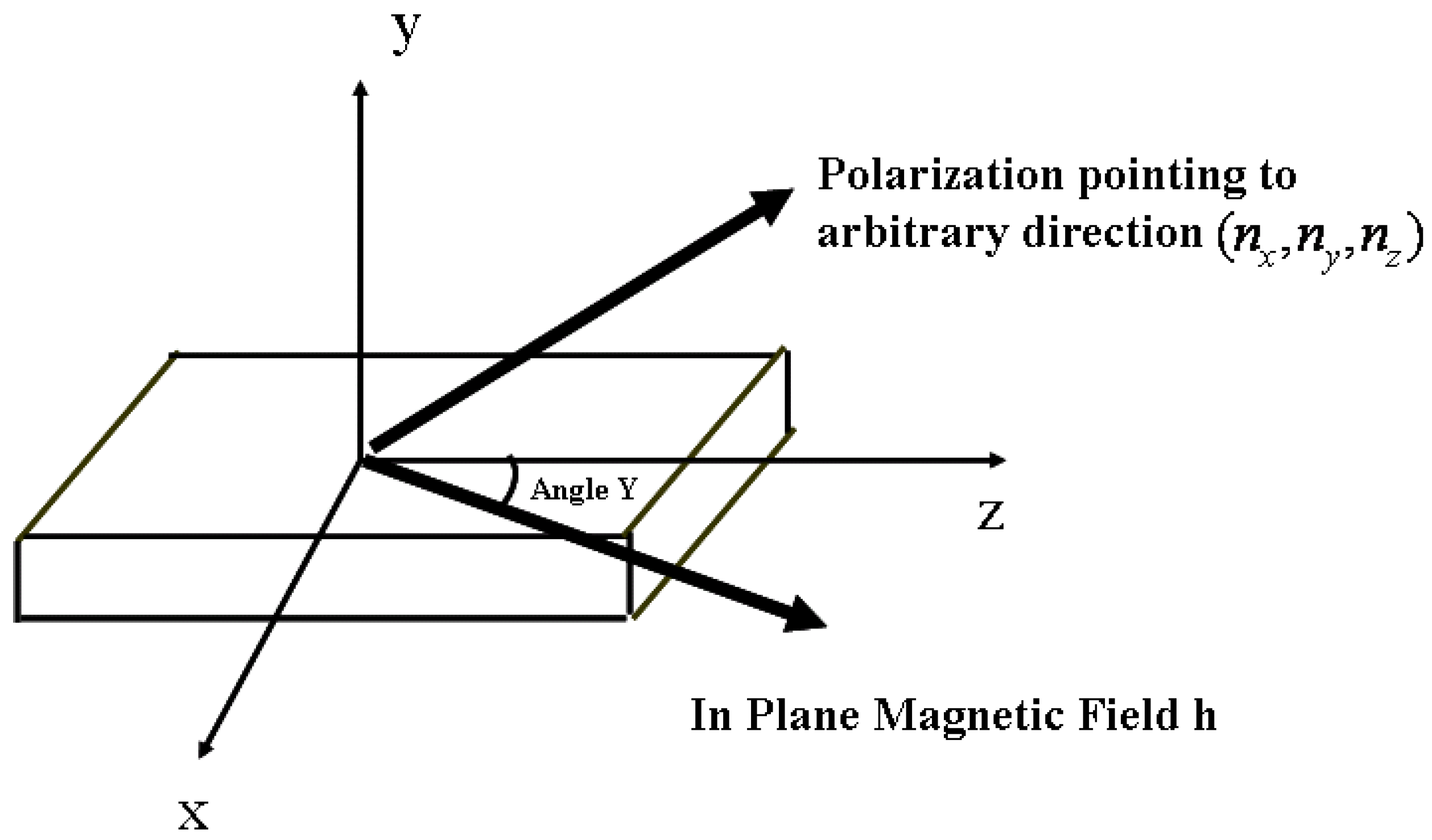
In this manuscript, we consider the dynamic thermal reversal of a magnetic element under combined magnetic field and spin torque excitation as in Figure 2. For the case of magnetic field lying in the plane X–Z, the energy of the magnetic system is:
The spin polarization direction is . Here we neglect the non-adiabatic term (which is usually much smaller) and study the case of spin torque with proportional to the spin torque current magnitude.

Figure 2.
Configuration of the manuscript: magnetic element under combined magnetic field and spin torque current excitations.
2. Symmetry Effects on Magnetic Field Induced Magnetization Switching
As an introduction to symmetry effects on magnetization switching dynamics, let’s consider the simplest case where only an external magnetic field is acting on the element and the magnetic field is aligned along the z axis (Y = 0):
with . When there is no magnetic field, the stable equilibrium magnetization states are: with energy minimum . There are saddle points at between the two energy minimums and the energy barriers are . External magnetic field h in the opposite direction of the equilibrium magnetization increases the magnetization equilibrium energy to and lowers the saddle point magnetic energy to . For magnetic fields smaller than , there is an energy barrier between the two equilibrium magnetization states. For magnetic fields bigger than , the initial equilibrium magnetization state is destroyed and the magnetization relaxes to the final equilibrium state aligned to the external magnetic field.
The critical magnetic field required to switch the magnetization is called the coercivity. The energy barrier determines the element’s thermal stability. For long time thermal decay, a Neel-Arrhenius type formula is used to link thermal fluctuation induced switching time to this energy barrier: , where is the switching time, is the attempt frequency, is the thermal agitation energy and is the element stability energy barrier. In magnetic field induced magnetization switching, the coercivity and stability barrier are the two most important parameters for writability and readability.
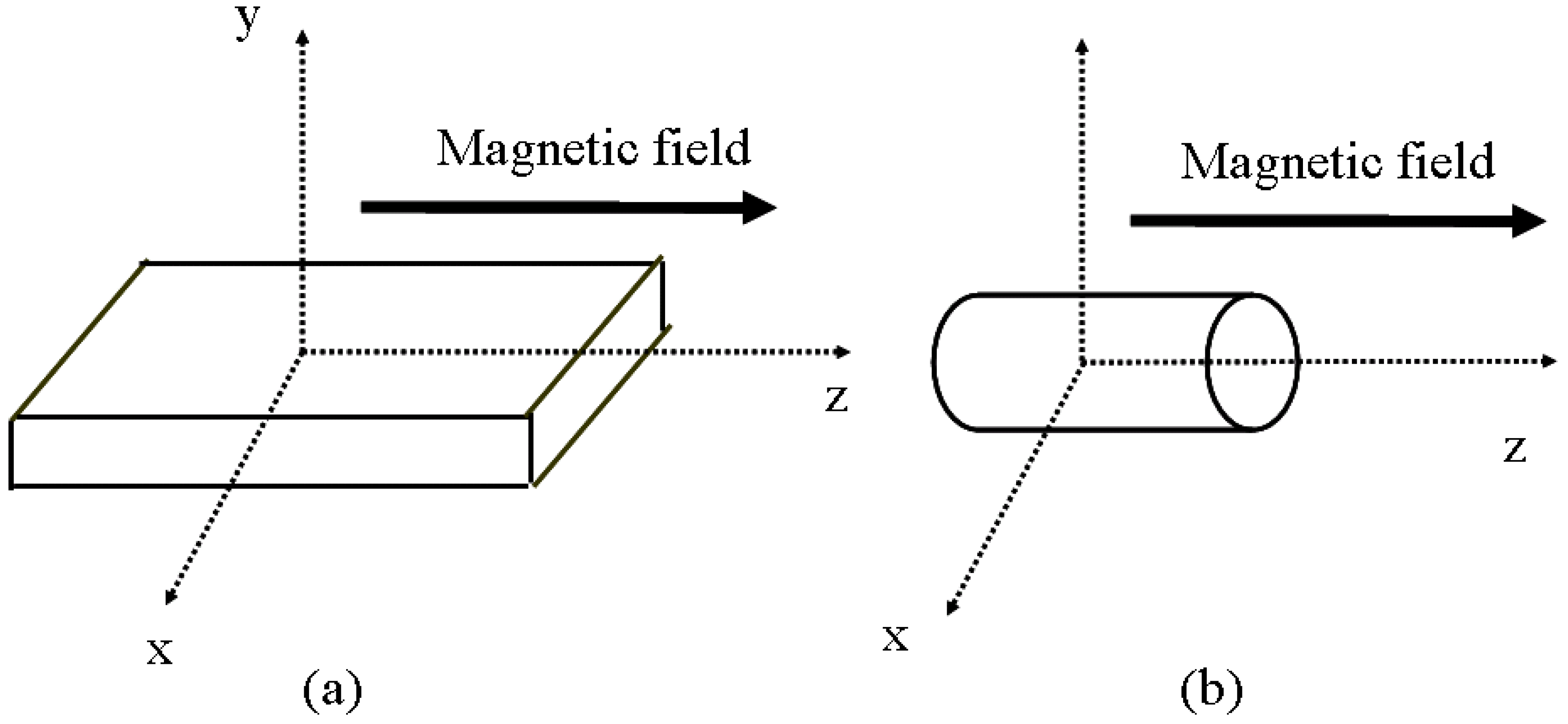
Based on the above energy surface analysis, the coercivity and energy barrier depend only upon anisotropy difference . Thus, for an elongated magnetic element, the coercivity and energy barrier do not depend upon its axial symmetry property. Figure 3 shows the example of two magnetic elements. The first magnetic element is a thin film element with due to strong out-of-plane demagnetization factor. The second element has cylindrical axial symmetry with . If is the same for these two elements, they will have the same coercivity and energy barrier independent of shape anisotropy factor .

Figure 3.
Configurations of thin film magnetic element without axial symmetry and magnetic element with cylindrical symmetry.
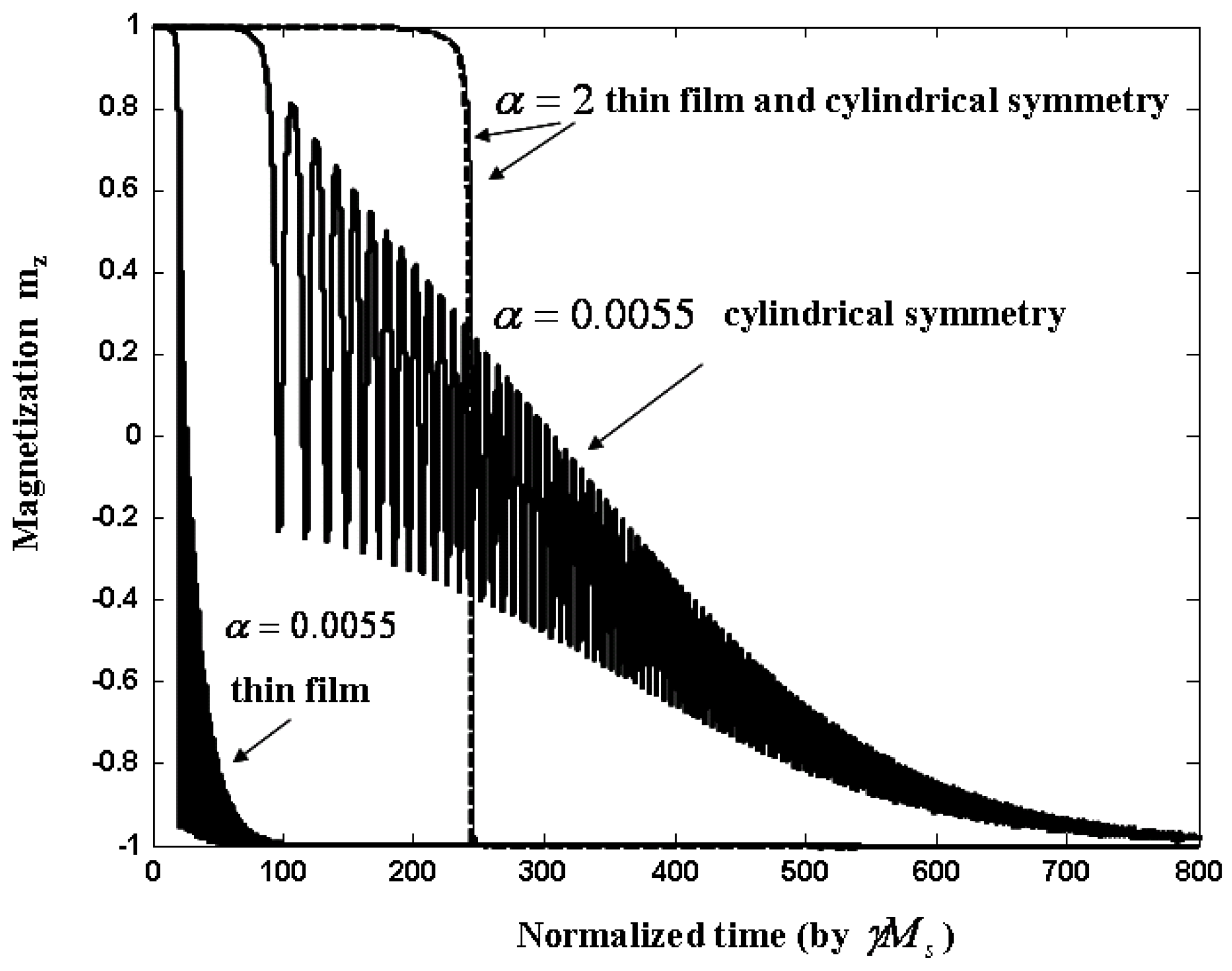
Figure 4 shows magnetization switching as a function of time (normalized by ) for two magnetic elements with same and different . It is a numerical simulation solving Landau-Lifshiltz-Gilbert (LLG) equation (2) at zero temperature. The thin film element has anisotropy factors: . The axial symmetric case is approximately represented by anisotropy factors: . The first case corresponds to a typical magnetic thin film element with strong out-of-plane demagnetization factor. The second relates to an element with perpendicular crystal anisotropy in z direction (thin film plane in x – y direction) as discussed in the introduction. The two elements have the same and quite different axial symmetry (). The external magnetic field magnitude is just above the coercivity value . In the case of large damping parameter , these two elements have similar switching behavior. However, in the case of small damping parameter , the two elements’ switching speeds are quite different. The thin film element switches much faster than the axial symmetric element. Damping parameter in ferromagnetic system includes both intrinsic and extrinsic relaxation processes. Intrinsic damping is small (~ 0.005) and usually refers to ferromagnetic relaxation process. Extrinsic damping is due to coupling of magnetic system to other sub-systems. Depending on the physical process, extrinsic damping parameter can vary in a large range. Large damping (0.1 ~ 1) is also chosen quite frequently in micromagnetic simulation for interacting magnetic grains.

Figure 4.
Dynamic switching of thin film magnetic element and magnetic element with cylindrical symmetry for big and small damping parameters. For big damping parameter, spatial symmetry difference between the thin film element and the cylindrical element does not affect the magnetization switching process. For small damping parameter, the difference in spatial symmetry plays an important role in magnetization switching behavior.
The symmetric effects on magnetization switching behavior for different damping parameters can be understood through analysis of the LLG equation at zero temperature. Without thermal fluctuation and spin torque terms, the LLG in spherical coordinates is:
The first terms on the right side of the equations are the gyro-magnetic term and the second terms are the damping term . The gyro-magnetic term rotates the magnetization along the constant energy level and the damping term moves the magnetization toward a lower energy level along the energy gradient direction .
In the limit of high damping parameter , the gyro-magnetic term can be neglected and the magnetization relaxes along the energy gradient. The magnetization reversal trajectory in the large damping case is constrained in a minimum energy plane. For the thin film element, this minimum energy plane is the thin film plane. For the cylindrically symmetric element, this plane can be any plane aligned to easy axis. Easy axis refers to the direction that magnetization prefers to settle at equilibrium condition. Here it is the z direction for smallest anisotropy factor (). Thus, the difference in spatial symmetry between the thin film element and the cylindrical element does not affect the magnetization switching process. The magnetization switching process for large damping parameter can be approximated by a one dimension dynamical system:
Only term enters into the solution of this one-dimensional system.
On the other hand, in the limit of low damping parameter , the magnetization precesses many circles around energy surface during the relaxation process. Magnetization trajectories are quite different for the thin film element and the axial symmetric element. The difference in spatial symmetry plays an important role in determining magnetization switching behavior. The analytical approximation for the small damping case can be pursued by averaging out fast rotating terms along constant energy levels. The justification for this approximation is that the magnetization traces many circles on a constant energy level before it relaxes to a lower energy level through small damping terms. A one dimensional dynamical system on energy level can be obtained as:
where is the averaged relaxation force on a particular energy level:
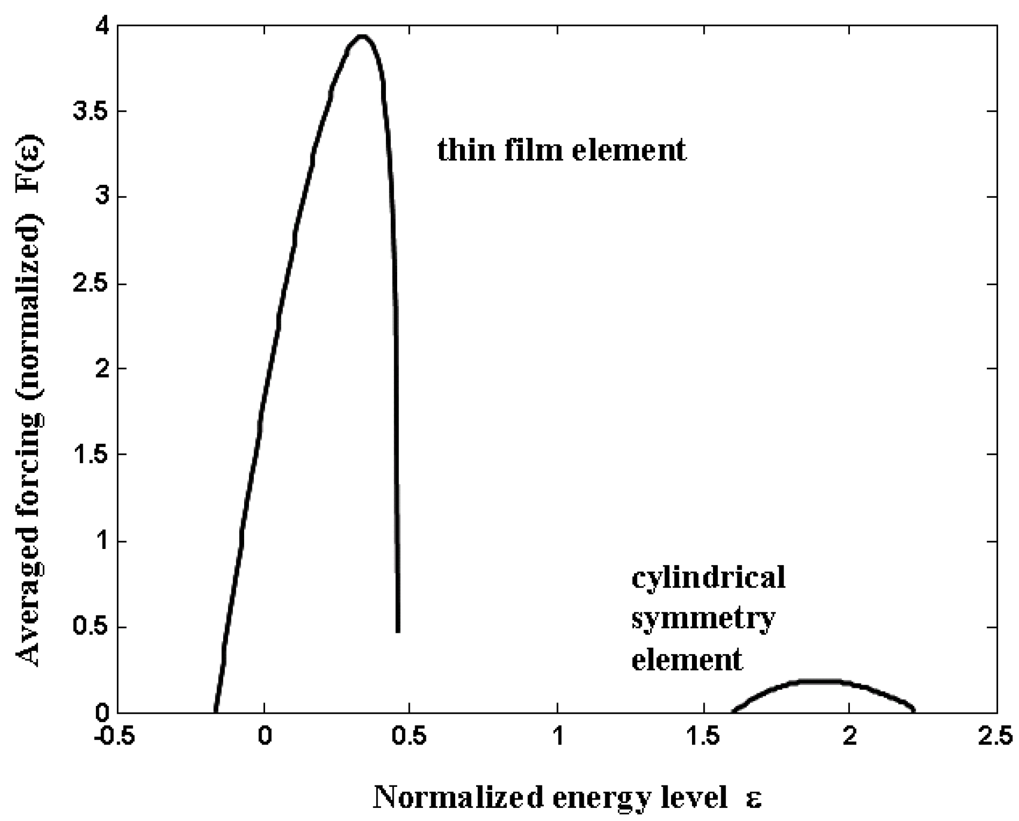
where are magnetization angles in spherical coordinates. is the integration around a constant energy level . Figure 5 shows the function for two elements. Although the difference between ending energy and starting energy is the same for the thin film element and the axial symmetric element, the thin film element does have a forcing much bigger than that of the axial symmetric element. As a result the thin film element switches much faster.

Figure 5.
Averaged forcing (normalized, unitless) versus normalized energy level for thin film magnetic element and magnetic element with cylindrical symmetry. The averaged forcing is significantly larger for thin film element.
3. Symmetry Effects on Critical Current of Spin Torque Induced Magnetization
The example in the previous section shows the effects of symmetry on switching speed for magnetic field induced magnetization switching. However, for a magnetic field aligned to the element’s long axis, the element’s coercivity and thermal stability barrier only depends upon the anisotropy difference . Also the element’s coercivity and thermal stability barrier scale the same. They are all proportional to . In this section, I will show dynamic symmetry effects on spin torque induced magnetization switching. The dynamic symmetry effects on spin torque induced switching are quite different from those of magnetic field induced switching. Dynamic symmetry plays more important roles in spin torque induced magnetization switching and this provides opportunities for improving spin torque device writability and readability.
For spin torque induced magnetization switching, the critical switching current is defined as the minimum polarized current magnitude to switch the magnetization. This is the writability parameter similar to coercivity in the magnetic field induced switching case. The readability parameter for spin torque switching is still the thermal stability barrier. However, for spin torque switching readability, instead of energy barrier dependence upon magnetic field, energy barrier dependence upon current magnitude is required.
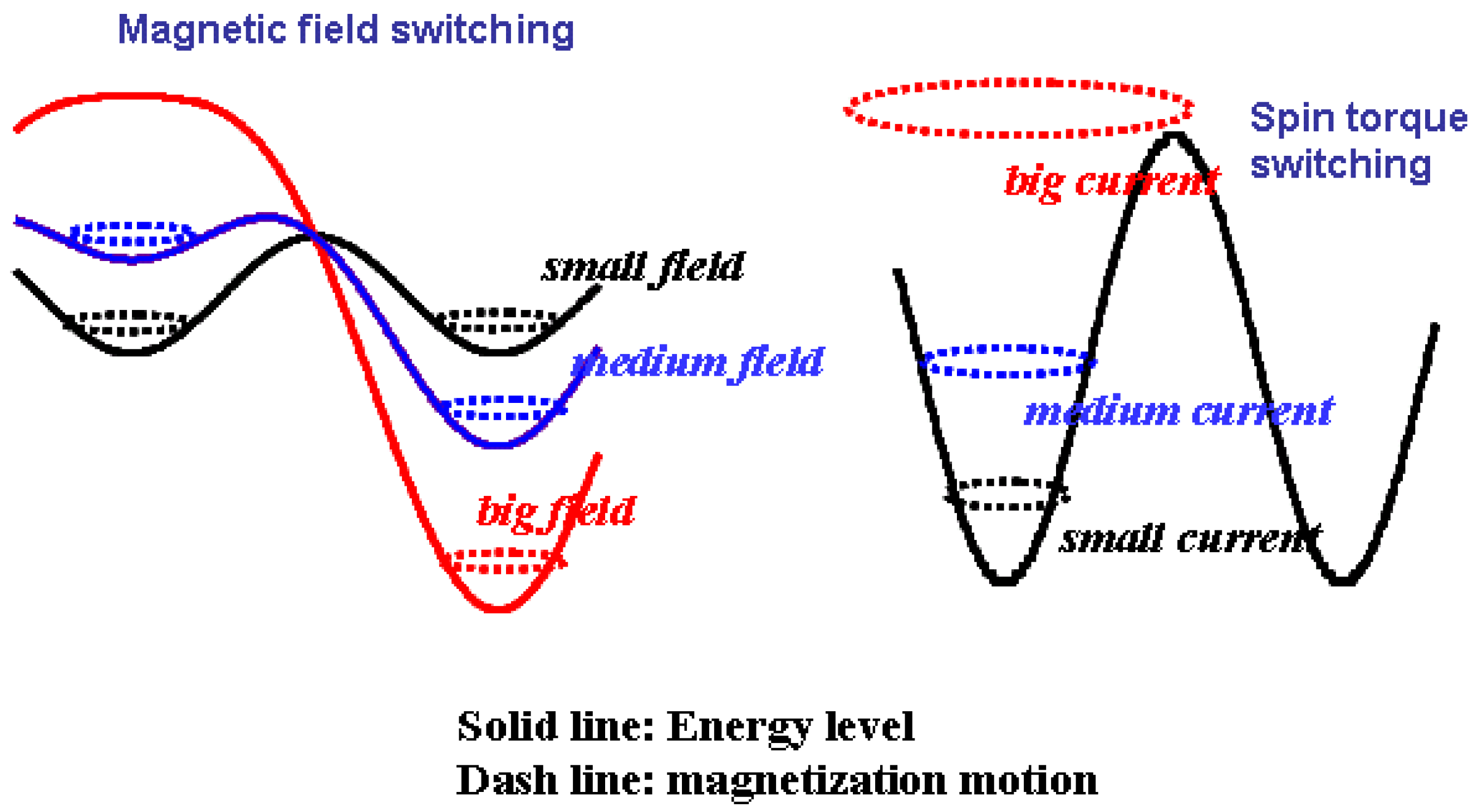
The dynamic picture of spin torque induced magnetization switching is quite different from that of magnetic field induced magnetization switching. This is illustrated in Figure 6. For magnetic field induced switching, the external magnetic field raises the initial equilibrium magnetization state energy and lowers the saddle point energy. When the magnetic field induced energy is bigger than the energy barrier between multi-stable magnetization states, the initial magnetization equilibrium state is destroyed and the magnetization evolves to its final equilibrium state through magnetization relaxation. However, for spin torque induced magnetization switching, spin torque excites magnetization precession out of the initial equilibrium state. In this process, there are always two equilibrium magnetization states and damping (or magnetization relaxation) tries to pull the magnetization back to its initial equilibrium state. Spin torque switching is a competition between spin torque excitation and magnetization damping.

Figure 6.
Schematic picture of magnetization switching mechanism difference for spin torque induced switching and magnetic field induced switching.
The stochastic LLG with spin torque term at finite temperature (2) can be written in spherical coordinates as two dimensional stochastic differential equations:
where are Gaussian random variables with zero mean and variance 1. is the thermal fluctuation magnitude. The two dimensional stochastic differential equations (9) can be simplified to a one dimensional system for small damping parameter (which is usually true for ferromagnetic material). For small damping parameter, a stochastic averaging technique [18,19] allows equation (9) to be integrated around constant energy levels to obtain the following one dimensional stochastic differential equation for energy levels:
where is a deterministic term and is a stochastic term. is the increment of a standard Brownian process. term can be explicitly written as:
where are magnetization angles in spherical coordinates. is the integration around a constant energy level . For the general case of polarization pointing at an arbitrary direction () in magnetic element’s coordinate (Figure 2), B and C terms in (11) can be expressed as:
The stochastic term can be explicitly written as:
The justification for this stochastic average technique is the same as in previous section: for small damping parameter, magnetization traces many circles on a constant energy level before it is changed by small damping and thermal fluctuations. Notice that the thermal fluctuation magnitude is proportional to damping through the fluctuation-dissipation condition. Small damping implies small thermal fluctuations.
The critical switching spin current density is determined by the minimum that gives a positive value of the expression
for all energy levels. Notice formula (14) is the numerator of equation (11) with set to zero. In the case of spin polarization pointing to the z direction (), Formula (14) gives a proportionality for the critical switching current:
We see immediately that critical switching current scales differently compared to coercivity and thermal stability barrier. Spin torque switching current scales with the difference between out-of-plane demagnetization factor and in-plane demagnetization factors , while coercivity and thermal stability energy scales as the difference between in-plane demagnetization factors . For a thin film element as in Figure 2, due to the strong out of plane demagnetization factor. Formula (15) implies that spin torque critical switching current is penalized quite a lot by the out of plane demagnetization factor.
The scaling difference between spin torque switching and magnetic field switching is the result of different magnetization switching dynamics as explained in Figure 6. For spin torque induced magnetization switching, spin torque excites magnetization precession out of the initial equilibrium state. Magnetization switching needs to be achieved through magnetization precessing out of the thin film plane. Strong out of plane demagnetization in thin film elements brings the energy penalty that results in critical switching current being proportional to the out of plane demagnetization factor.
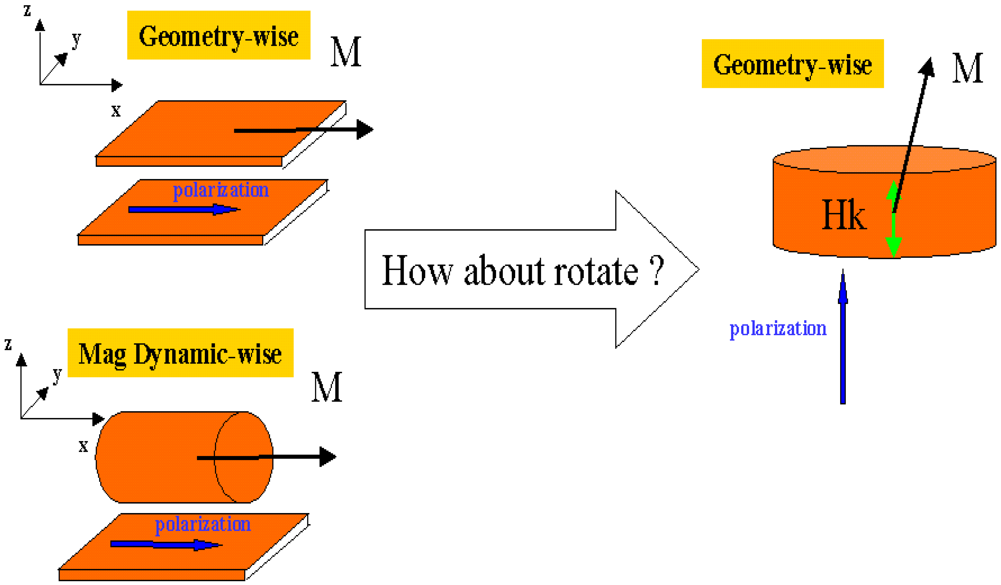
The scaling difference between thermal stability and spin torque switching current provides an opportunity to decrease spin torque current density without sacrificing thermal stability. The approach is to bring more cylindrical dynamic symmetry to magnetization switching. The reduction of spin current without sacrificing thermal stability can be achieved by reduction of out of plane demagnetization factor and at the same time maintain the difference in in-plane demagnetization factor . The ultimate goal of this approach is to reach cylindrical symmetry in magnetization dynamics as illustrated in Figure 7. When magnetization dynamics are cylindrically symmetric, the spin torque critical switching current scales the same as the thermal stability barrier.

Figure 7.
Approach leads to the same scaling of spin torque switching current and thermal stability barrier: the importance of magnetization switching dynamic symmetry.
For practical application, the challenge is to keep a geometrically thin film structure at the same time. A thin film geometric structure is essential for many other required device properties, such as a high magnetoresistance ratio. One solution to achieve cylindrically symmetric magnetization dynamics and thin film geometric structure at the same time is illustrated in Figure 7. When we rotate the configuration of thin film element with cylindrical symmetry magnetization dynamics, we recognize that this can be achieved by a thin film element with big perpendicular crystal anisotropy. Indeed for a thin film with perpendicular anisotropy much bigger than the out-of plane demagnetization factor, the critical spin torque switching current scales the same as the thermal stability barrier.
Another interesting difference between spin torque induced and magnetic field induced switching is the different angular dependence of critical switching current and coercivity. For magnetic field induced switching, when the magnetic field is not perfectly aligned to the long axis of the element, the coercivity decreases. The angular dependence of coercivity is the well known Stoner-Wohlfarth curve [20]: , where Y is the angle between the applied magnetic field direction and the magnetic element long axis. This formula can be obtained by analyzing the energy surface: . Again, because the onset of magnetic field induced switching results from annihilation of the energy barrier, the coercivity can be obtained by the analysis of magnetic energy with constrained magnetization .
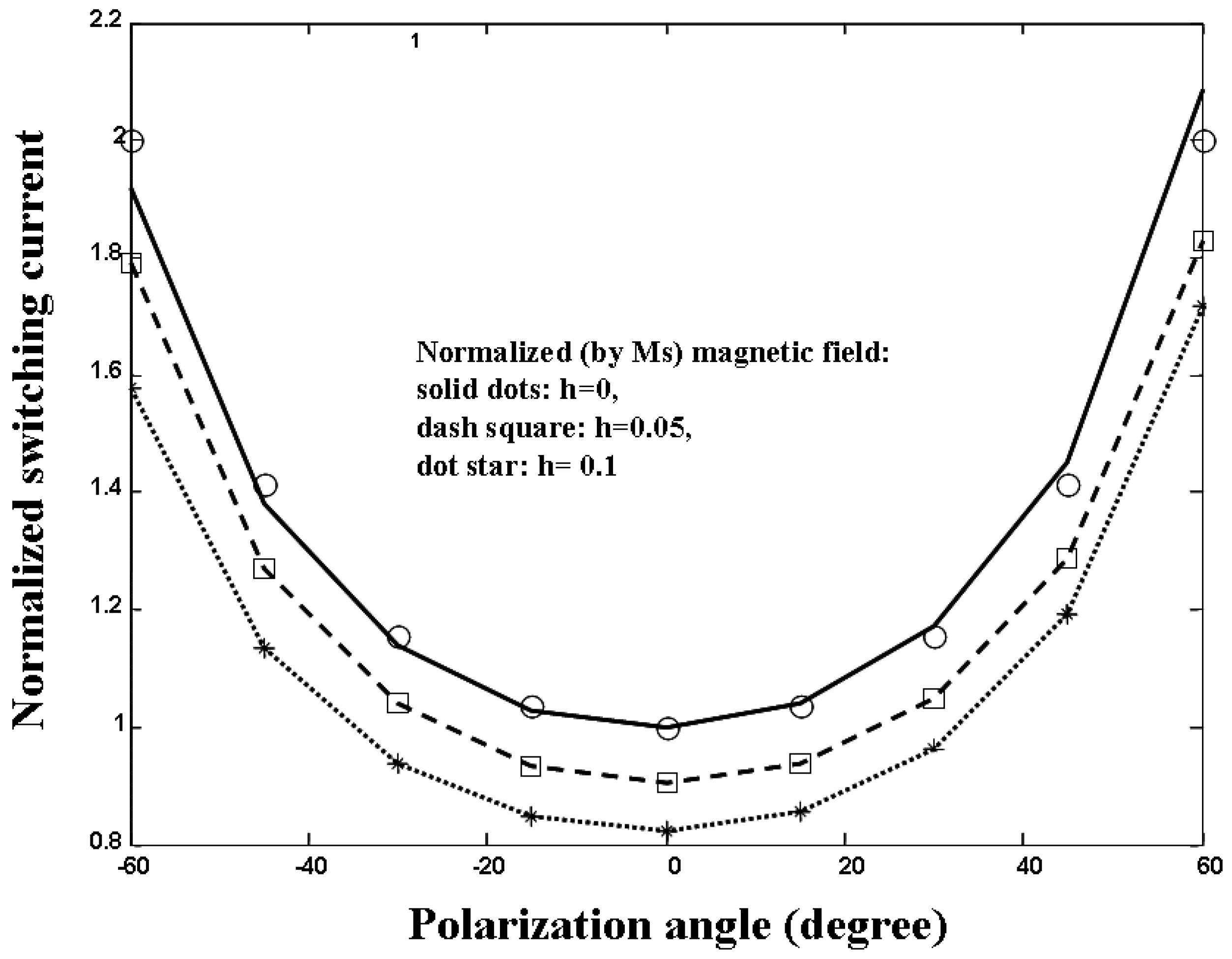
Figure 8 shows the angular dependence of critical switching current for a magnetic element. Spin polarization direction is in-plane and has an angle X relative to the easy axis of the element (). Here we consider the more general case where an additional magnetic field points to the easy axis of magnetic element. After normalizing to the critical switching current at X=0, the angular dependence of switching currents lies on the universal curve for all external magnetic fields with amplitudes below coercivity. This angular dependent critical switching current is quite different from angular dependent coercivity. When the spin polarization direction is not perfectly aligned to the long axis of the element, the critical spin current increases. This result has been discovered in [21].

Figure 8.
Critical spin torque switching current versus polarization angle for different magnetic field magnitudes. After normalization to the critical switching current at zero polarization angle, they all follow the universal curve of 1/cos(polarization angle).
For the general case of spin polarization pointing to an arbitrary direction (), the angular dependence of the critical switching current can be obtained through symmetry arguments. In the case of magnetic field pointing to the easy axis of the magnetic element, the only nonzero part of spin torque term in the integration expression of (14) is . All the parts of term in the integration are zero due to the symmetric condition that is an even function of for . Thus the critical switching current for a magnetic field pointing to easy axis of the element is proportional to . This is independent of magnetic field amplitude, element geometric dimensions and magnetic properties.
4. Symmetry Effects on Magnetic Element Stability under Spin Torque Excitation
For long time thermal reversal, when switching current is much less than the critical switching current, a Neel-Arrhenius type formula can be used to link the observed thermal switching time to the spin torque current , where is the switching time, is the attempt frequency, is the thermal agitation energy and is the thermal reversal barrier for spin torque induced thermal magnetization switching. is the critical switching current at zero temperature, which has been defined in the previous section.
The thermal stability barrier for magnetic field induced switching was discussed in section II. For an external magnetic field pointing to the easy axis of the element, the magnetic field energy barrier scales with magnetic field as:
where is the critical switching field at zero temperature. is the energy barrier at zero external magnetic field. Formula (16) is an exact solution based upon energy surface analysis. It can also be obtained by exact solution of stochastic differential equation (9). One important property of formula (16) is that this functional scaling relation between the energy barrier (normalized by ) and the external magnetic field (normalized by ) is independent of element geometric shape and magnetization dynamics symmetry. The same functional relationship between normalized reversal barrier and normalized magnetic field holds whether it is a thin film element or a cylindrically symmetric element.
However, for spin torque magnetization dynamics, the situation is quite different. Due to dynamic effects of spin torque switching, the functional scaling relation between the energy barrier (normalized by ) and the spin torque current (normalized by ) depends upon element geometric shape and magnetization dynamic symmetry.
Let’s first consider the case of an element with cylindrical symmetry (). In this case, , and the stochastic Landau-Lifshitz-Gilbert equation (LLG) in spherical coordinates (9) can be simplified to a one-dimensional system only involving :
Notice, that in the cylindrically symmetric case, the spin torque term ( has exactly the same format as the external magnetic field term and can be treated formally as an effective field term. According to formula (16), thermal reversal barrier for spin torque current switching should be:
for the cylindrically symmetric case.
For the general asymmetric case (), when the damping parameter is small, the stochastic LLG can be integrated around constant energy levels to give a one dimensional stochastic differential equation for energy levels as shown in section III. It can be shown that a global stationary distribution exists for such a one-dimensional stochastic dynamical system [22]. The stationary distribution satisfies:
where Z is the normalization factor and U is related to energy of the system as:
where the integrations are for the a constant energy level . The functions and are called “melnikov functions”. Notice here is not an equilibrium distribution in the statistical mechanics sense; instead it is a stationary out-of-equilibrium distribution induced by spin polarized current, gyromagnetic motion and damping dynamics. The function has to be understood as an “effective potential” which governs the stochastic dynamics of the system. The spin torque induced reversal barrier is:
where is the energy at stable equlibrium state and is the energy at transition saddle point.
In the case of cylindrical symmetry (), the normalized magnetic field switching coercivity is and the normalized critical switching current is . The melnikov functions can be easily calculated as:
The spin torque induced reversal barrier is:
Equation (23) gives . In the thermal reversal region, for , . Written in a dimensional format, this gives Equation (18). This shows that the approach of stochastic averaging with an “effective potential” does give results consistent with the exact solution of the Fokker-Planck equation for the cylindrically symmetric case.
For the general case without cylindrical symmetry, , exact solutions of the melnikov functions can be obtained:
where and are complete elliptic integral of the first and second kind. The normalized magnetic field switching coercivity is and the normalized critical switching current is: . The thermal reversal barrier is:
Equation (25) can be written in following form:
with a thermal symmetry factor :
(26) implies:
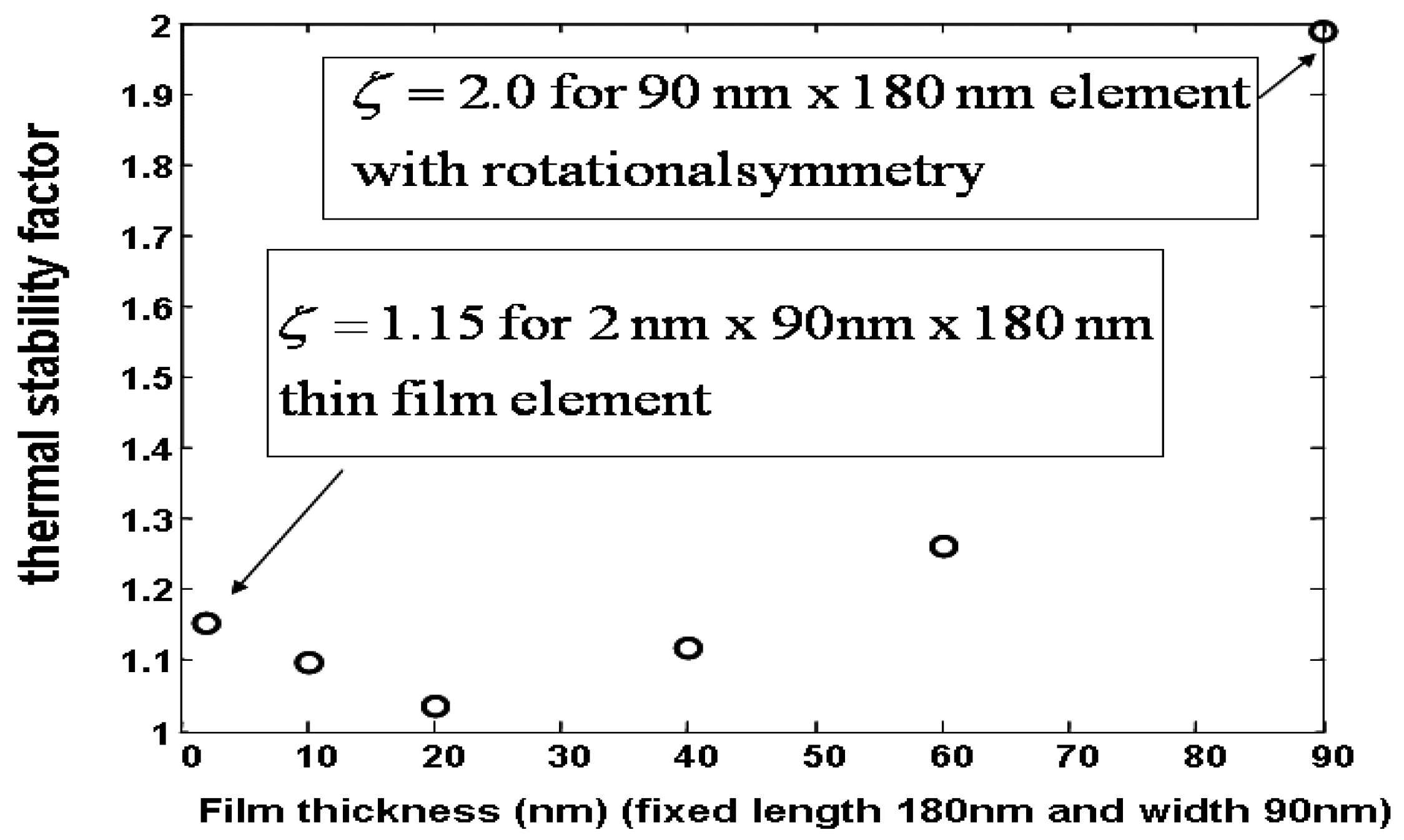
where the symmetry factor depends upon magnetic element symmetry. Figure 9 shows an example of the dependence of upon magnetic element geometric shape. approaches 2 for the cylindrically symmetric case, consistent with the exact solution of the Fokker-Planck equation and is close, but bigger than 1 for the thin film element case. For an example of a rectangular element with dimension 180nm × 90nm × 2nm, equals to 1.15.

Figure 9.
Thermal stability factor dependence upon magnetic element symmetry.
The dependence of thermal stability factor on magnetization symmetry implies that there is no universal scaling between the normalized thermal reversal barrier and the normalized switching current density for spin torque induced magnetization switching. A symmetric factor that depends upon element anisotropy factors must be considered when scaling the thermal reversal barrier to switching current. [23] studied spin torque current fluctuation effects on spin torque induced magnetization switching. Theoretical and experimental work showed that fluctuating current effects on spin torque switching strongly depends upon magnetization dynamics symmetry.
5. Dynamic Symmetry Information and Damping Parameter Extraction through Magnetization Logarithmic Susceptibility
The effects of dynamic symmetry and damping parameter on magnetization switching have been illustrated in previous sections. In this section, I will present a method to extract this information based upon the concept of logarithmic magnetization susceptibility.
Logarithmic susceptibility (LS) is a concept originally proposed for the study of the probability of large infrequent fluctuations in non-adiabatically driven systems [24,25]. For a thermally activated magnetization process, magnetization logarithmic susceptibility can be defined as a change of the activation reversal barrier due to external forcing at various frequencies. External forcing here can be either external magnetic field or spin torque. Because thermally activated magnetization reversal naturally involves large angle magnetization dynamics, logarithmic susceptibility provides rich information on nonlinear magnetization dynamics and possible ways to control the thermal magnetization activation rate.
We consider the case of spin polarization pointing along the easy axis of a magnetic element (z axis). Using notation from reference [26], the stochastic LLG (2) can be written as:
where is the normalized magnetization, , is the thermal fluctuation magnitude and , are the standard Brownian motions. The gyro-magnetic rotation term and damping terms are:
and thermal fluctuation terms are:
For long time thermal reversal with and external driving forces well below critical switching forces, the magnetization switching is determined by the optimal reversal path, which is the minimization of the action functional of the above stochastic system [26,27,28]:
The thermal reversal barrier is determined by:
Which, with the minimization function , gives the optimal reversal path. For the case of no external forcing, , it can be proven that
Substituting (34) into (32) gives and only for the optimal path that satisfies:
with the boundary conditions that is at an equilibrium point at and that is at a transition saddle point at . Note that in equation (35) the term and terms have .
In the case of thermal magnetization switching excited by a time varying external spin torque current , the action functional is:
where and represent gyro-magnetic motion and damping dynamics due to time varying external forces. Using relation (35), the action functional for time varying perturbation forces can be approximated to the leading order as:
The energy barrier decrease due to external time varying perturbations is:
Here we consider periodic spin torque driving , where is the driving frequency. The optimal reversal path is:
and external driving force is:
The reversal barrier reduction due to periodic spin torque driving can be obtained:
The logarithmic susceptibility is defined as the reversal barrier reduction due to external periodic driving:
where is the magnetization logrithmic susceptibility. If an external periodic forcing is composed of many harmonic frequency components, , the reversal barrier reduction can be calculated as:
For a single frequency component, the roll-off of logrithmic susceptibility with frequency determines the decreasing effects of reversal barrier reduction as the driving AC frequency increases.
For the simplest case of a magnetization element with cylindrical symmetry: , an analytical solution can be obtained for the optimal path:
Note here time is normalized by . The logarithmic susceptibility is:
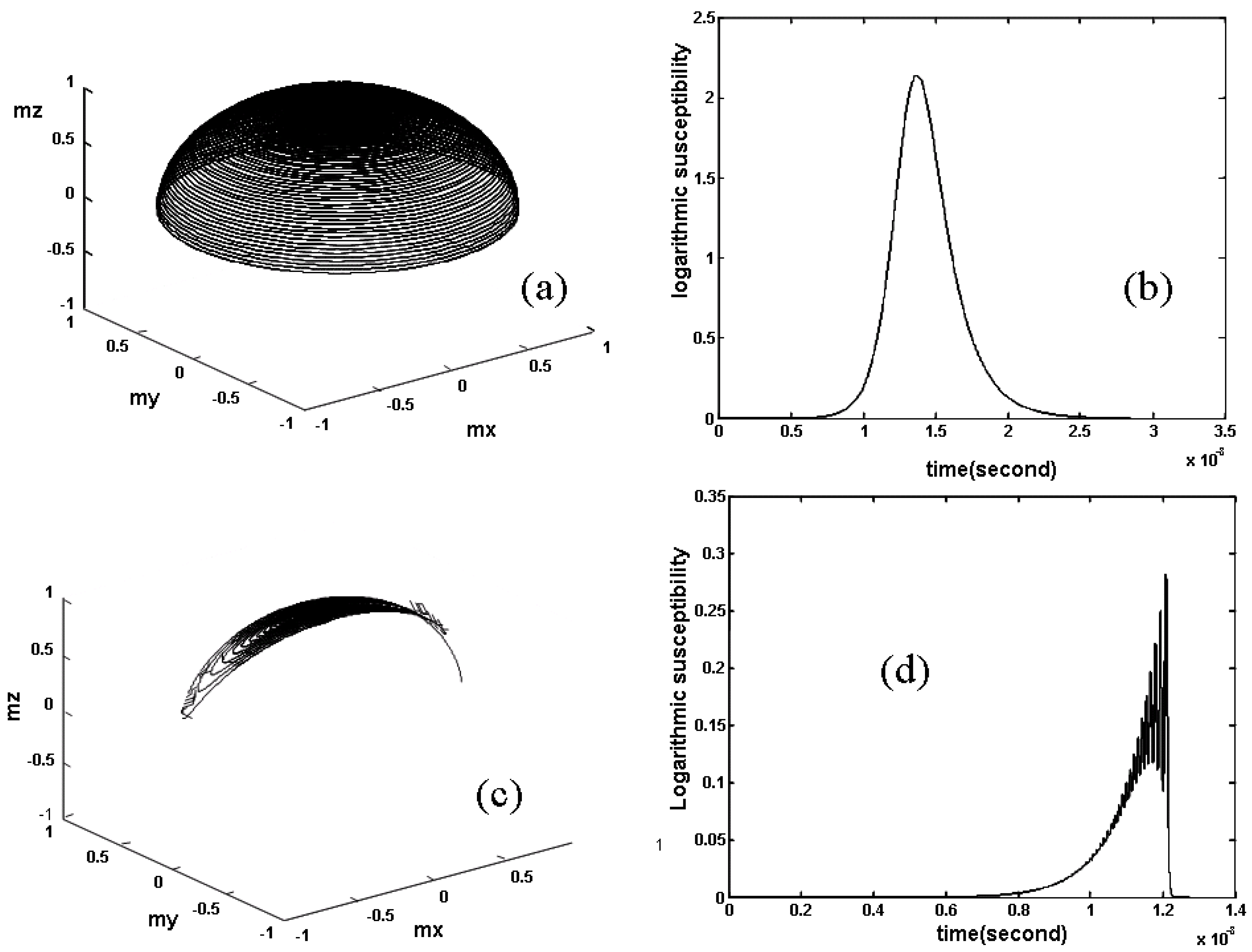
Figure 10 shows the optimal reversal path for a cylindrical symmetric case with saturation magnetization and demagnetization factor . The logarithmic susceptibility in the time domain is also shown in Figure 10. The damping parameter here is 0.0055. Figure 11(a) shows the frequency response of the logarithmic susceptibility for different damping parameters. It is clear from this figure that the logarithmic susceptibility’s frequency response is quite sensitive to the damping parameter. Thus, the damping parameter of the element can be obtained by fitting to the frequency dependence of the logarithmic susceptibility. For practical application, the energy barrier reduction required for the calculation of logarithmic susceptibility frequency response can be obtained from measured magnetization switching time.

Figure 10.
(a) Optimal reversal path and (b) time domain logarithmic susceptibility for a magnetization element with cylindrical symmetry. (c) Optimal reversal path and (d) time domain logarithmic susceptibility for a thin film magnetic element with strong out-of-plane demagnetization factor.

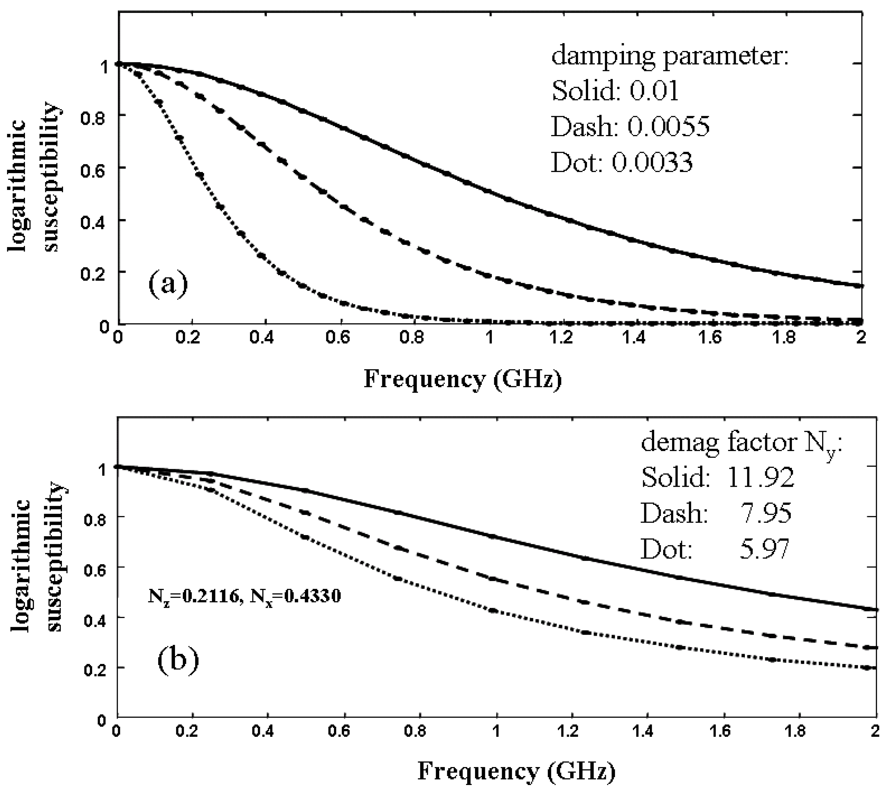
Figure 11.
(a) Frequency dependence of logarithmic susceptibility upon damping parameters for a magnetic element with rotational symmetry. (b) Frequency dependence of logarithmic susceptibility upon magnetization symmetry for magnetic thin film elements with different demagnetization factors. Logarithmic susceptibility’s frequency response is quite sensitive to the damping parameter and magnetization dynamic symmetry.
For magnetization dynamics without cylindrical symmetry, numerical solutions need to be used to obtain the optimal reversal path (35) and logarithmic susceptibility (42). Figure 10 shows the optimal reversal path for a thin film element with 180nm length, 90nm width and 2nm thickness. The magnetization saturation is 1000emu/cc and damping parameter is 0.0055. Also shown on the figure is the optimal reversal path in the time domain. Compared to the cylindrically symmetric case, the magnetization trajectory for thin film element is highly elliptical. This is because the out-of-plane demagnetization factor of the thin film element strongly suppresses the out-of–plane component of the magnetization motion. For a thin film element, the optimal path involves interactions between high frequency gyromagnetic rotation and low frequency damping dynamics. This is quite different from the cylindrically symmetric case (where gyromagnetic motion and damping are effectively separated). The high frequency fluctuations of the time domain logarithmic susceptibility are a signature of this interaction between gyromagnetic motion and damping dynamics. It is also through this interaction that symmetries of magnetization dynamics are revealed. Figure 11 shows the frequency response of the logarithmic susceptibility for different demagnetization factors, corresponding to magnetization dynamics with different symmetries. The case of corresponds the simulation in Figure 10. It is clear from Figure 11 that magnetization dynamics symmetry can be obtained by fitting to the frequency response of logarithmic susceptibility. Experiment measurements were done in [29] to determine a ferromagnetic thin film element’s damping parameter through logarithmic susceptibility.
The logarithmic susceptibility also provides a path to control spin torque induced switching in a fluctuating environment. During the reading of a magnetic element, the high frequency read current can be designed to minimize its perturbations on the magnetization stable state.
6. Conclusions
Symmetry effects on spin torque and magnetic field induced magnetization switching were studied. Compared to magnetic field induced switching, dynamic symmetry plays more important roles in spin torque induced magnetization switching. Dynamic symmetry effects on the critical switching current and the spin torque perturbed stability barrier were obtained and their implications to practical device design were discussed. Logarithmic magnetization susceptibility was used to extract symmetry and damping information on spin torque induced nonlinear magnetization dynamic processes.
Acknowledgement
Author gives special thanks to Gene Sandler for editing and read-proofing this manuscript.
References
- Berger, L. Emission of spin waves by a magnetic multilayer traversed by a current. Phys. Rev. B 1996, 54, 9353–9358. [Google Scholar] [CrossRef]
- Slonczewski, J.C. Current driven excitation of magnetic multilayers. J. Magn. Magn. Mater. 1996, 159, L1–L7. [Google Scholar] [CrossRef]
- Stöhr, J.; Siegmann, H.C.; Kashuba, A.; Gamble, S.J. Magnetization switching without charge or spin currents. Appl. Phys. Lett. 2009, 94, 072504. [Google Scholar] [CrossRef]
- Stanciu, C.D.; Hansteen, F.; Kimel, A.V.; Kirilyuk, A.; Tsukamoto, A.; Itoh, A.; Rasing, T. All-Optical magnetic recording with circularly polarized light. Phys. Rev. Lett. 2007, 99, 047601. [Google Scholar] [CrossRef]
- Brown, W.F. Thermal fluctuations of a single domain particle. Phys. Rev. 1963, 130, 1677–1686. [Google Scholar] [CrossRef]
- Krivorotov, I.N.; Emley, N.C.; Garcia, A.G.F.; Sankey, J.C.; Kiselev, S.I.; Ralph, D.C.; Buhrman, R.A. Temperature dependence of spin-transfer-induced switching of nanomagnets. Phys. Rev. Lett. 2004, 93, 166603. [Google Scholar] [CrossRef] [PubMed]
- Li, Z.; Zhang, S. Thermal assisted magnetization reversal in the presence of a spin-transfer torque. Phys. Rev. B 2004, 69, 134416–134421. [Google Scholar] [CrossRef]
- Apalkov, D.M.; Visscher, P.B. Spin-torque switching: Fokker-Planck rate calculation. Phys. Rev. B 2005, 72, 180405. [Google Scholar] [CrossRef]
- Garcia-Palacios, J.L.; Lazaro, F.J. Langevin-dynamics study of the dynamical properties of small magnetic particles. Phys. Rev. B 1998, 58, 14937–14958. [Google Scholar] [CrossRef]
- Theodonis, I.; Kioussis, N.; Kalitsov, A.; Chshiev, M.; Butler, W.H. Anomalous bias dependence of spin torque in magnetic tunnel junctions. Phys. Rev. Lett. 2006, 97, 237205. [Google Scholar] [CrossRef] [PubMed]
- Salahuddin, S.; Datta, D.; Srivastava, P.; Datta, S. Quantum transport simulation of tunnel based spin torque transfer (STT) devices: Design trade offs and torque efficiency. In Proceedings of the IEEE International Electron Devices Meeting, Washington, DC, USA, 10 December 2007; p. 121. [Google Scholar]
- Xiao, J.; Bauer, G.E. Spin-transfer torque in magnetic tunnel junctions: scattering theory. Phys. Rev. B 2008, 77, 224419–224427. [Google Scholar] [CrossRef]
- Heiliger, C.; Stitles, M.D. Ab Initio studies of the spin-transfer torque in magnetic tunnel junctions. Phys. Rev. Lett. 2008, 100, 186805. [Google Scholar] [CrossRef] [PubMed]
- Rebei, A.; Hitchon, W.N.G.; Parker, G.J. s-d-type exchange interactions in inhomogeneous ferromagnets. Phys. Rev. B 2005, 72, 064408–064419. [Google Scholar] [CrossRef]
- Manchon, A.; Ryzhanova, N.; Strelkov, N.; Vedyayev, A.; Chshiev, M.; Dieny, B. Modeling spin transfer torque and magnetoresistance in magnetic multilayers. J. Phys. Condens. Matter. 2007, 19, 165212. [Google Scholar] [CrossRef]
- Haney, P.M.; Duine, R.A.; Nunezc, A.S.; MacDonald, A.H. Current-induced torques in magnetic metals: Beyond spin transfer. J. Magn. Magn. Mater. 2008, 320, 1300. [Google Scholar] [CrossRef]
- Wang, X.; Zhu, W.; Dimitrov, D. Quantum transport and stochastic magnetization dynamics simulation on intrinsic spin torque switching asymmetry. Phys. Rev. B 2009, 79, 104408. [Google Scholar] [CrossRef]
- Wang, X.; Bertram, H.N.; Safonov, V. Thermal-dynamic reversal of fine magnetic grains with arbitrary anisotropy axes orientation. J. Appl. Phys. 2002, 92, 2064–2072. [Google Scholar] [CrossRef]
- Wang, X.; Zheng, Y.; Xi, H.; Dimitrov, D. Thermal fluctuation effects on spin torque induced switching: Mean and variations. J. Appl. Phys. 2008, 103, 034507. [Google Scholar] [CrossRef]
- Stoner, E.C.; Wohlfarth, E.P. A mechanism of magnetic hysteresis in heterogeneous alloys. Philos. Trans. R. Soc. London. Ser. A 1948, A240, 599–642. [Google Scholar] [CrossRef]
- Sun, J.Z. Spin-current interaction with a monodomain magnetic body: A model study. Phys. Rev. B 2000, 62, 570–578. [Google Scholar] [CrossRef]
- Bonin, R.; Serpico, C.; Bertotti, G.; Mayergoyz, I.D.; d’Aquino, M. Analytical study of magnetization dynamics driven by spin-polarized currents. Eur. Phys. J. B 2007, 59, 435–445. [Google Scholar] [CrossRef]
- Wang, X.; Zhu, W.; Dimitrov, D. Current fluctuations and magnetization dynamics symmetry in spin-torque-induced magnetization switching. Phys. Rev. B 2008, 78, 024417–024421. [Google Scholar] [CrossRef]
- Smelyanskiy, V.N.; Dykman, M.I.; Rabitz, H.; Vugmeister, B.E. Fluctuations, escape, and nucleation in driven systems: Logarithmic susceptibility. Phys. Rev. Lett. 1997, 79, 3113. [Google Scholar] [CrossRef]
- Lehmann, J.; Reimann, P.; Hanggi, P. Surmounting oscillating barriers. Phys. Rev. Lett. 2000, 84, 1639. [Google Scholar] [CrossRef] [PubMed]
- Kohn, R.V.; Reznikoff, M.G.; Vanden-Eijnden, E. Magnetic elements at finite temperature and large deviation theory. J. Nonlinear Sci. 2005, 15, 223–253. [Google Scholar] [CrossRef]
- Wang, X.; Bertram, N.H.; Safonov, V.L. Thermal induced reversal in coupled grains and elongated particles. J. Appl. Phys. 2002, 91, 6920–6922. [Google Scholar] [CrossRef]
- Wang, X.; Juan, J.F.; Gao, K.; Jin, Z. Thermal reversal of magnetic grains under time varying pulse field. IEEE Trans. Magn. 2006, 42, 2294–2296. [Google Scholar] [CrossRef]
- Wang, X. Magnetization logarithmic susceptibility, damping parameter, and dynamics symmetry extraction. Appl. Phys. Lett. 2008, 93, 182506. [Google Scholar] [CrossRef]
© 2010 by the authors; licensee MDPI, Basel, Switzerland. This article is an open-access article distributed under the terms and conditions of the Creative Commons Attribution license (http://creativecommons.org/licenses/by/3.0/).