Article

Theoretical and Numerical Study on Buckling Analysis of Cylindrical Shell Structures by Galerkin and Finite Element Methods

1
Institute of Structural Mechanics, Bauhaus-University Weimar, 99423 Weimar, Germany
2
Department of Physics, College of Science, Imam Mohammad Ibn Saud Islamic University (IMSIU), Riyadh 11623, Saudi Arabia
*
Author to whom correspondence should be addressed.
Symmetry 2026, 18(9), 1448; https://doi.org/10.3390/sym18091448
Submission received: 1 August 2026 / Revised: 20 August 2026 / Accepted: 25 August 2026 / Published: 28 August 2026
(This article belongs to the Special Issue Applications Based on Symmetry in Solid Mechanics)

Abstract

The structural instability of cylindrical shells has long attracted scholarly attention due to its inherently nonlinear response and extensive engineering relevance. Although numerous investigations have examined buckling phenomena arising from individual loading modes such as axial compression or pure torsion, the complex behavior of shells subjected to simultaneous torsional and axial actions remains comparatively underexplored. In this study, an integrated approach combining theoretical formulations and finite element analyses is employed to comprehensively characterize the buckling responses of cylindrical shells under coupled torsional–axial loading conditions. The theoretical framework is developed using Donnell’s shell theory and solved through the Galerkin approximation. The predicted results exhibit strong agreement with finite element simulations. It is demonstrated that the buckling evolution of cylindrical shells under combined loading markedly differs from that produced by a single load component. Specifically, shells under torsion with minor compression display a stable deformation mode, whereas higher compression induces a transition toward a diamond-shaped buckling pattern. Such findings elucidate the coupled torsion–compression/tension effects governing buckling instabilities in cylindrical shells, offering valuable insight for the design of load-responsive foldable and origami-inspired structures driven by combined mechanical actions.

1. Introduction

The phenomenon of buckling in cylindrical shells has captivated the mechanics community for over a century, serving both as a gateway to understanding nonlinear instability and as a foundation for ensuring the structural integrity of shell-based systems. Over the decades, extensive studies have examined various facets of cylindrical shell buckling, encompassing the determination of critical loads [1,2,3], the evolution of post-buckling pathways [4], the sensitivity to imperfections [5,6,7], and the formation of wrinkling morphologies [8,9,10]. It is well established that, under sufficient axial compression, a cylindrical shell undergoes instability and forms an axisymmetric or diamond-shaped buckling pattern, whereas pure torsion gives rise to a diagonal deformation mode [11]. Thin-walled cylindrical shells continue to epitomize the paradox of lightweight efficiency and severe imperfection sensitivity: minor geometric deviations can depress the classical elastic buckling load by large factors, complicating design and qualification. A century after the foundational developments that culminated in widely used empirical knock-down factors, contemporary work has reframed shell buckling as a problem governed by localization, energy barriers, and stability landscapes, with corresponding implications for simulation and testing [3,12,13]. Modern studies show that axially compressed cylinders often collapse via localized dimple patterns rather than delocalized classical eigenmodes, which demands numerical approaches capable of tracing complex post-buckling paths and capturing sensitivity to measured imperfection fields [12,13,14]. Moreover, the finite element method is proven to be a powerful tool in analyzing the behavior of structures [15,16,17].
From the stability-landscape viewpoint, buckling is triggered when the system crosses an energy barrier along a preferred localized route. Non-destructive probing methods—which impose lateral displacements at selected points—map this landscape and relate measured probe responses to the true single-specimen capacity. A sequence of contributions has established and matured this concept: the laboratory probing idea and theory [18], ridge-tracking demonstrations on imperfect shells [19], and targeted probing at initiation sites for accurate prediction [20]. Recent extensions adapt probing to stiffened cylinders and practical configurations [21] and translate it into design-oriented energy-barrier frameworks [22,23]. These developments are accompanied by careful experiments on post-buckled structures that validate the probing paradigm and illustrate the role of metastable states and softening paths [24,25]. Together, they provide a rich dataset against which to calibrate and verify high-fidelity simulations [19].
On the numerical side, modern finite element strategies deploy arc-length/Riks continuation with imperfection seeding informed by measured geometry or by deterministic constructs such as SPLA-type perturbations; they must also resolve mode localization and track complicated secondary bifurcations. Comprehensive comparisons of imperfection patterns and lower-bound strategies, together with DESICOS-style workflows, have mapped the consequences of eigenmode, dimple, axisymmetric, and measured fields for predicted capacity [26]. Systematic studies of boundary conditions and local buckling modes provide additional validation targets for analysts [27]. Beyond deterministic analysis, robust design frameworks—validated experimentally—now offer less conservative but safe knock-down factors by explicitly embedding imperfection sensitivity and model-form uncertainty [28,29,30].
Recent loading scenarios extend beyond uniform axial compression: localized axial compression [31,32], external pressure on isotropic and composite shells [33,34], and under combined torsional and compression loading [35]. These works emphasize that imperfections, load eccentricity, and thickness variation modulate not only the peak capacity but also the localization footprint and post-buckled evolution—features that simulations must reproduce to be credible.
In the broader context of structural mechanics, various analytical and numerical methodologies have been established to address the boundary value problems of plates and shells. While numerical schemes such as the finite element method (FEM) offer versatility for complex geometries, analytical solutions remain indispensable for providing fundamental physical insights and benchmark results. Beyond traditional semi-inverse methods, the finite integral transform (FIT) technique has emerged as a robust and unified analytical framework for solving non-Lévy-type plate and shell problems [36,37]. This approach bypasses the need for pre-determining trial deformation functions and can strictly satisfy both the governing differential equations and diverse boundary conditions, including rotationally restrained and free edges [38,39]. Recent advancements have successfully applied FIT-based schemes to investigate the free vibration of functionally graded (FG) porous plates [36,38], the buckling behavior of Mindlin plates under complex constraints [37], and the mechanical response of composite structures [40]. By transforming complex partial differential equations into simple matrix eigenvalue problems, these analytical schemes provide high precision and computational efficiency for modern engineering applications.
Despite this extensive body of work, prior studies have primarily focused on single loading modes, either pure compression or pure torsion, leaving the combined torsional and axial buckling problem relatively unexplored. Elastic structures subjected to multiple concurrent loads often display richer and more complex instability phenomena than those observed under single load. For instance, varying the twisted angle and applied torsion in a ribbon can produce transitions among multiple deformation modes, from helicoidal and longitudinally buckled states to creased helicoids and localized loops [41]. Similarly, bending a ribbon before twisting can trigger snap-through instabilities. In such nonlinear buckling problems, the response under combined loading cannot generally be obtained by superposition of the single-load responses. Consequently, the structure exhibits inherently nonlinear behavior under combined loading, where the resulting instability cannot be captured by the linear superposition of single-load responses.
Although the stability of cylindrical shells under individual mechanical or thermal loads has been widely studied, their buckling and post-buckling responses under combined thermo-mechanical loading conditions remain insufficiently understood, particularly for functionally graded shells. This issue represents an important research gap because such coupled loading states frequently arise in practical engineering applications and are difficult to reproduce systematically through laboratory experiments. Therefore, the present study investigates the stability behavior of functionally graded cylindrical shells under complex loading combinations using validated semi-analytical and finite element models.
This work systematically investigates the buckling and post-buckling behavior of cylindrical shells subjected to simultaneous axial and/or torsional loading using finite element analysis (FEA). The theoretical formulation is established within the shell theory defined by Donnell and resolved with Galerkin’s approach. A phase diagram is created from the buckling analysis, illustrating the buckling morphology and critical load of a cylindrical shell which is clamped on both sides and subjected to various loading conditions. The post-buckling analysis elucidates the equilibrium trajectories and pattern evolution principles for shells under pre-torsion and compression or torsion and compression.
The main innovation of the present work lies in the combined use of Donnell’s shell theory and the Galerkin method to capture modal transition behavior in the nonlinear post-buckling regime, while also providing results that are consistent with finite element simulations. However, the method is subject to several assumptions and limitations. In particular, the shell is assumed to be thin, homogeneous, isotropic, and geometrically perfect, and the analysis is restricted to the classical shell theory framework. Effects such as material nonlinearities, geometric imperfections, initial residual stresses, and dynamic loading are not considered in the present study. Therefore, the applicability of the model is mainly limited to thin cylindrical shells under quasi-static combined loading conditions.
Experimentally characterizing the post-buckling response of FG cylindrical shells under complex, multi-axial thermo-mechanical loadings poses significant challenges and prohibitive laboratory costs. In this context, validated numerical and semi-analytical frameworks offer an efficient and cost-effective alternative. Furthermore, cross-validating the semi-analytical Donnell–Galerkin formulation with comprehensive finite element simulations ensures high predictive reliability and robustness for engineering design and structural assessment.

2. Model and Physics of the Problem

This section employs the shell theory proposed in Ref. [1] to derive the buckling/post-buckling reactions of a slender cylindrical shell under axial load and torsional torque. This classical theory is commonly utilized for analyzing the nonlinear mechanical behavior of thin-walled shell structures due to its analytical simplicity and dependable forecasting capabilities. For the sake of conciseness, just the final version of the governing equations obtained from the Donnell formulation is provided here. To ensure numerical accuracy, reliability, and convergence, the governing equations were discretized using a Galerkin-series approach with an appropriate truncation level. Unless otherwise specified, M = 4 terms were retained for the critical buckling calculations, whereas 38 terms were used for the post-buckling analyses. These truncation levels provided an appropriate balance between computational efficiency and the required accuracy for the slender shell geometries considered. It was also observed that cylinders with higher h/r ratios require additional series terms to achieve full convergence, consequently increasing the computational cost.

2.1. Mathematical Formulation

Figure 1a,b illustrate the geometry and computational grid, respectively. Following the sign convention widely adopted in prior studies of shell buckling under axial compression [4], (F > 0) denotes compression, whereas (F < 0) corresponds to tension. Both loads are distributed around the edges of the shell, generating axial stress. A Cartesian coordinate system ( x 1 , x 2 , x 3 ) is defined on the mid-surface of the shell, with the ( x 1 )-axis aligned along the longitudinal direction, the ( x 2 )-axis along the circumferential direction, and the ( x 3 )-axis oriented radially. The nonlinear equations that describe the shell’s large-deflection behavior under the combined axial and torsional loads can be expressed as follows:
D 4 u 3 1 r 2 ψ x 1 2 = 2 ψ x 2 2 2 u 3 x 1 2 2 2 ψ x 1 x 2 2 u 3 x 1 x 2 + 2 ψ x 1 2 2 u 3 x 2 2
4 ψ + E h r 2 u 3 x 1 2 = E h 2 u 3 x 1 x 2 2 2 u 3 x 1 2 2 u 3 x 2 2
D represents the flexural rigidity, ψ signifies the Airy’s stress function and u 3 denotes the transverse displacement. The boundary conditions for clamped endpoints at x 1 = L / 2 and L / 2 are specified as follows:
u 3 = u 3 x 1 = 2 ψ x 1 2 v 2 ψ x 2 2 = 3 ψ x 1 3 + ( 2 + v ) 3 ψ x 1 x 2 2 = 0
0 2 π R     n x 1 d x 2 = F ,   r 0 2 π r     n x 1 x 2 d x 2 = T
Here, n x 1 , n x 2 , and n x 1 x 2 are the resultant forces in the shell. Furthermore, the end shortening and twisting angle can be respectively computed by
Δ = 1 2 π r 0 2 π r   L / 2 L / 2   1 E h 2 ψ x 2 2 v 2 ψ x 1 2 1 2 u 3 x 1 2 d x 1 d x 2
φ = 1 2 π r 2 0 2 π r   L 2 L 2   2 1 + v E h 2 ψ x 1 x 2 + u 3 x 1 u 3 x 2 d   x 1 d x 2
For the evaluation of critical buckling, the resultant forces corresponding to the pre-buckling condition are as follows:
N x 0 = 2 F 0 x 2 2 = F 2 π r ,   N x 1 x 2 0 = 2 F 0 x 1 x 2 = T 2 π r 2 ,   N x 2 0 = 2 F 0 x 1 2 = 0 .
By neglecting the nonlinear components in the fundamental equations, the following expressions are obtained:
c ¯ 4 u 3 ¯ α 2 ψ x 1 2 = k x 2 u 3 ¯ x 1 2 + 2 k s β c 2 u 3 ¯ x 1 x 2 ,   ¯ 4 ψ + α 2 u 3 ¯ x 1 2 = 0 ,
c ¯ 4 u 3 ¯ + α 2 ¯ 4 4 u 3 ¯ x 1 4 + k x 2 u 3 ¯ x 1 ¯ 2 2 k s β c 2 u 3 ¯ x 1 x 2 ¯ = 0 .
For a shell structure with both ends clamped, the nondimensional transverse displacement u 3 may be expressed in the following form:
u 3 ¯ ( x ¯ , y ¯ ) = m = 1   a m ϕ m 1 ( x 1 ¯ , x 2 ¯ ) + ϕ m + 1 ( x 1 ¯ , x 2 ¯ )
with
ϕ m = c o s ( m x 1 ¯ + x 2 ¯ ) + ( 1 ) m c o s ( m x 1 ¯ x 2 ¯ )
Subsequently, the Galerkin technique is applied, resulting in the following condition:
0 2 π   π / 2 π / 2   L 0 ( w ¯ ) ϕ j 1 ( x 1 ¯ , x 2 ¯ ) + ϕ j + 1 ( x 1 ¯ , x 2 ¯ ) d x 1 ¯ d x 2 ¯ = 0 ,   j = 1 , 2 , 3 , M
with
n = 1 M     a n P n 1 + Q n 1 A n 1 , j + ( 1 ) n 1 P n 1 Q n 1 B m 1 , j + P m + 1 + Q n + 1 A m + 1 , j + ( 1 ) n + 1 P n + 1 Q n + 1 B n + 1 , j = 0 , j = 1 , 2 , , M
Then, we have
P m = c m 2 + β 2 2 + α 2 m 4 m 2 + β 2 2 k x 1 m 2
Q m = 2 k x 1 β c m
A m , j = 0 2 π     π / 2 π / 2     c o s ( m x 1 ¯ + x 2 ¯ ) ϕ j 1 ( x 1 ¯ , x 2 ¯ ) + ϕ j + 1 ( x 1 ¯ , x 2 ¯ ) d x 1 ¯ d x 2 ¯
For the post-buckling investigation, the nondimensional transverse deflection u 3 ¯ ( x 1 ¯ , x 2 ¯ ) is assumed to take the following form:
u 3 ¯ ( x 1 ¯ , x 2 ¯ ) = m = 1   n = 0   a m , n ξ m 1 , n + ξ m + 1 , n ,   m = 1 , 2 , 3 , ,   n = 0 , 1 , 2 ,
with
ξ m , n = c o s ( m x 1 ¯ + n x 2 ¯ ) + ( 1 ) m c o s ( m x 1 ¯ n x 2 ¯ )
4 ψ = p = 0   q = 0   ψ P q ξ p , q ,   p , q = 0 , 1 , 2 , ;   f 00 = 0
And with
ψ P q = α p 2 a P 1 , q + a P + 1 , q 1 16 β 2 4 2 δ P 0 δ q 0 3 ( 1 ) p n = 1   n = 0   a m , k Y ( p , q , m , n )
Y ( p , q , m , n ) represents a linear combination of a m , n , which can be written as
Y ( p , q , m , n ) = Y p , q , m 1 , n + Y p , q , m + 1 , n Y p , q , r , s = a ( p , q , r , s ) + a ( p , q , r , s ) + a ( p , q , r , s )     + ( 1 ) p [ a ( p , q , r , s ) + a ( p , q , r , s ) ]     + ( 1 ) r [ a ( p , q , r , s ) + a ( p , q , r , s ) ]     + ( 1 ) p + r [ a ( p , q , r , s ) + a ( p , q , r , s ) ]
where
a ( p , q , r , s ) = ( p s q r ) 2 a p + r 1 , q + s + a p + r + 1 , q + s
ψ ( x 1 ¯ , x 2 ¯ ) = 1 2 V k x 1 + p = 0     1 + ( 1 ) p ( 1 ) p / 2 p 2 F p 0 x 1 ¯ 2 k x 2 β 2 x 2 ¯ 2 c k 3 β x 1 ¯ x 2 ¯ + p = 0     q = 0     B p q ξ P , q
Here, we have
B P q = F P q + G P q ,   B p 0 = F p 0 ,   F p q = ψ p q p 2 + β 2 q 2 2 ,   F 00 = 0
G P q = 2 2 δ p 0 1 δ q 0 S p q k = 0     1 + ( 1 ) p + k ( 1 ) p + k 2 k 2 v β 2 q 2 F k p
S P q = p 2 v β 2 q 2 p 2 + β 2 q 2 2 ( 1 ) p c o s h ( π β q ) 1 ( 1 + v ) π β q ( 3 v ) s i n h ( π β q ) ( 1 ) p ( 1 + v ) π β q

2.2. Numerical Approach

Finite element simulations were conducted to analyze the buckling responses of cylindrical shells subjected to combined torsional and axial loading. The ABAQUS 2022 commercial software is used for simulation. The model employed a three-dimensional shell representation with a constant radius r = 200 mm. The length and thickness of the shell were varied according to the prescribed radius-to-thickness (r/t) and length-to-radius (L/r) ratios adopted in each numerical case. The material was assumed to have a Young’s modulus of (E = 4.0 GPa) and a Poisson’s ratio of 0.4.
In all analyses, a four-node shell element was employed with reduced integration to avoid locking. For the clamped–clamped boundary configuration considered, the lower end of the shell was fully clamped, whereas the upper edge, where the external loads were introduced, was permitted to translate and rotate along the longitudinal axis.
The essential buckling force and corresponding circumferential wavenumber were derived from an eigenvalue buckling analysis. For pure compression, a slight concentrated axial force was exerted, whereas for pure torsion, a minimal twisting moment was applied. In the scenario of concurrent compression and torsion, both perturbations were introduced simultaneously. In simulations of torsion with pre-tension or pre-compression and compression with pre-torsion, reflecting the post-buckling scenarios, the appropriate preload was first supplied before the introduction of the linear perturbation. The minimal eigenvalue derived from the analysis determines the critical buckling force, whereas the associated eigenmode delineates the critical wavenumber. The calculated eigenmodes were subsequently employed as initial geometric flaws to initiate bifurcation during the post-buckling phase.

3. Results

In this section, the numerical outcomes of the buckling analyses of clamped–clamped cylindrical shell subjected to axial force and torsional load are presented. Both the finite element analysis results and the theoretical predictions obtained through the Galerkin method are reported. The influences of combined loading conditions, the radius/thickness ratio (r/t), and the length/radius ratio (h/r) on critical buckling load, circumferential wavenumber, buckling mode, and post-buckling path are systematically examined. In buckling analysis, particular emphasis is placed on shells under the simultaneous action of torsion and compression. In both the theoretical framework and the FEA models, the loaded end of the shell is permitted to rotate and translate along its longitudinal axis. Unless otherwise specified, the Galerkin series solution retains four terms (M = 4) for the critical buckling computations and thirty-eight terms for the post-buckling analyses.

3.1. Validation of the Numerical Results

To begin, the accuracy of the Galerkin-based theoretical predictions is verified against the FEA results illustrated in Figure 2. The comparison demonstrates that, across all loading types and for C–C shells with various (r/t) ratios, the critical loads and corresponding circumferential wavenumbers obtained by the Galerkin method agree closely with the FEA outcomes.
The deformed configurations obtained from the finite element simulations are consistent with the buckling patterns predicted by the Galerkin formulation. In particular, the shell exhibits twisted diamond-shaped modes at lower pre-torsion levels, while the deformation gradually evolves toward a diagonal buckling pattern as the loading condition changes. This agreement between the analytical and numerical results indicates that the proposed model captures the essential deformation characteristics of the shell, including the observed diamond-to-diagonal mode transition.

3.2. Buckling Under Compression with Pre-Torsion

This section investigates the post-buckling response of clamped–clamped (C–C) cylindrical shells subjected to axial compression combined with pre-torsion. Four levels of pre-torsion are examined, namely T = 0, 0.30 Tcr0, 0.60 Tcr0, and 0.80 Tcr0, where Tcr0 denotes the critical buckling torque under pure torsion. The normalized axial load P is employed to express the results, with Pcr0 representing the critical buckling load under pure compression.
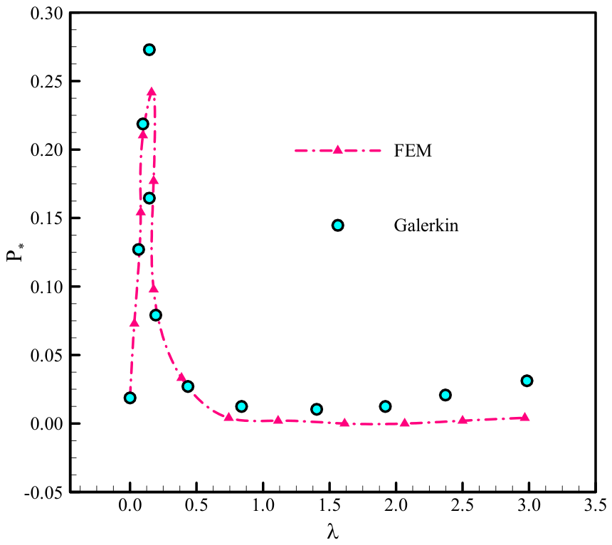
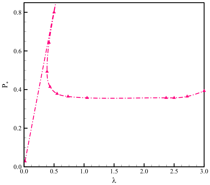
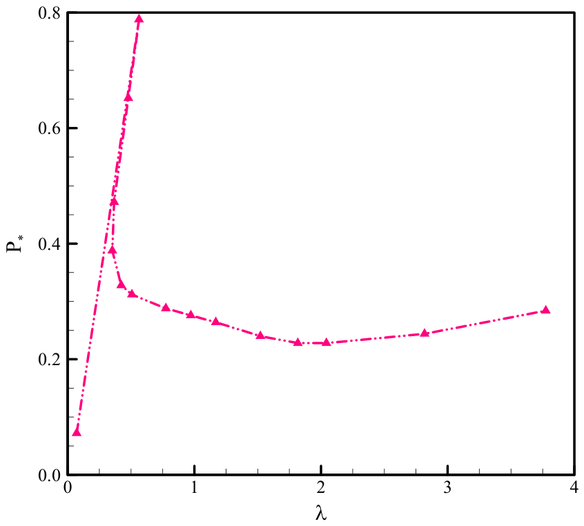
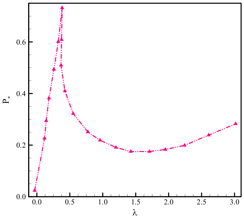
Figure 3 and Figure 4 illustrate the relationship between the normalized compressive load and the dimensionless end shortening λ for a C–C cylindrical shell characterized by r/t = 150 and h = 200 mm. The analysis compares finite element analysis (FEA) outcomes with those obtained from the Donnell–Galerkin theoretical model. Owing to the presence of slight geometric imperfections in the FEA models, the predicted critical loads (identified at the load–displacement curve peaks) are marginally lower than those obtained from the theoretical analysis. Both methods indicate an unstable post-buckling regime immediately after buckling, marked by a steep reduction in load capacity, implying a snap-through behavior and a substantial loss in stiffness. The theoretical predictions exhibit close agreement with the FEA results except near the snapping points, due to the force-controlled nature of the Galerkin formulation.
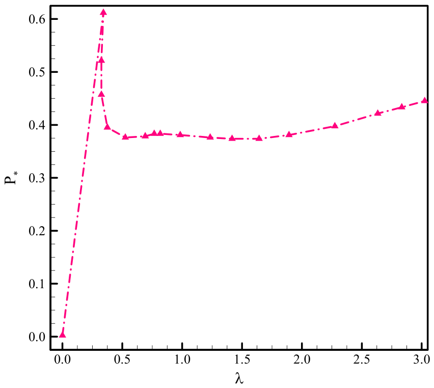
For cases with minimal or no pre-torsion (T0 = 0 and T0 = 0.30 Tcr0), the shell transitions between different buckling modes, each time reducing its circumferential wavenumber by one. The resulting patterns evolve from diamond-shaped configurations to larger wavelength modes after each snap, as depicted in Figure 5. When pre-torsion is small, the buckled configuration shows twisted diamond patterns that merge diagonally under compression. In contrast, for higher pre-torsion, as shown in Figure 6 and Figure 7 (T0 = 0.60 Tcr0 and 0.80 Tcr0), the shell immediately adopts a diagonal-form buckling (N = 12) with no further snap.
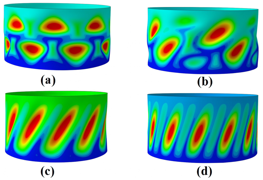
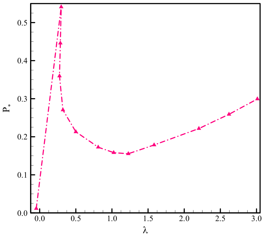
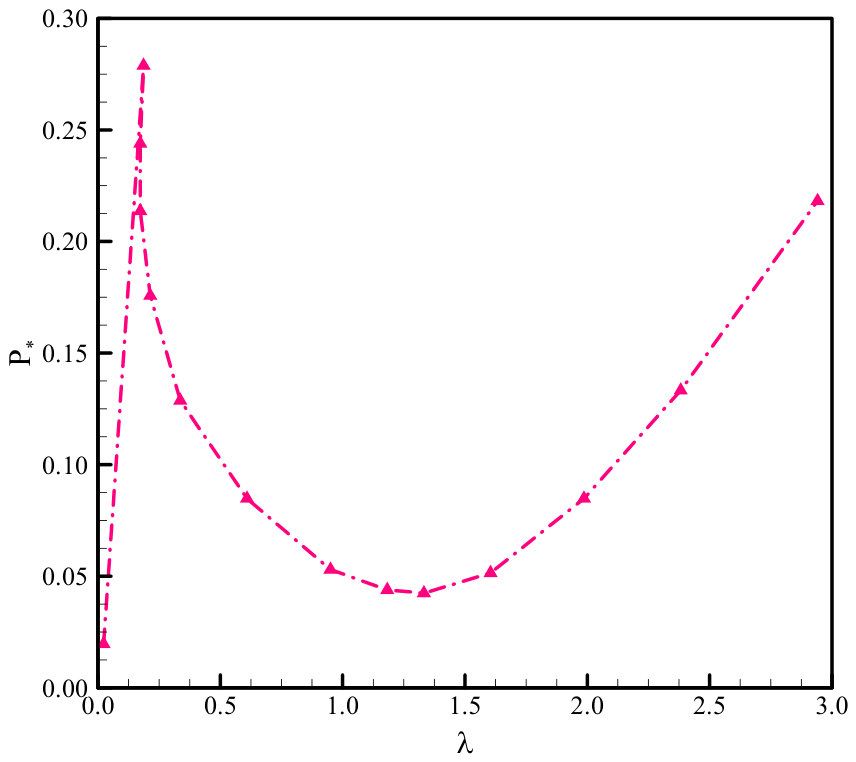
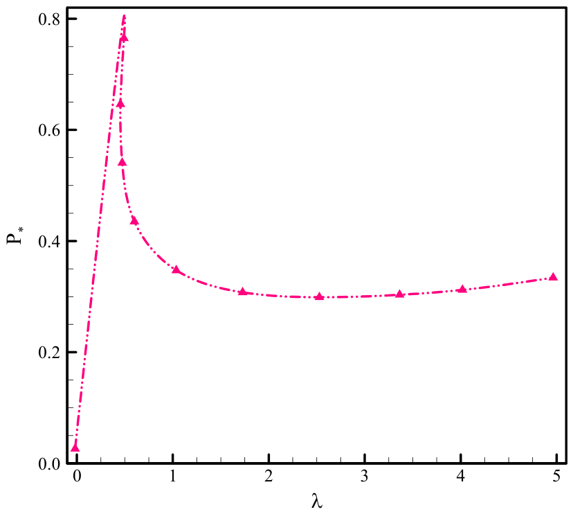
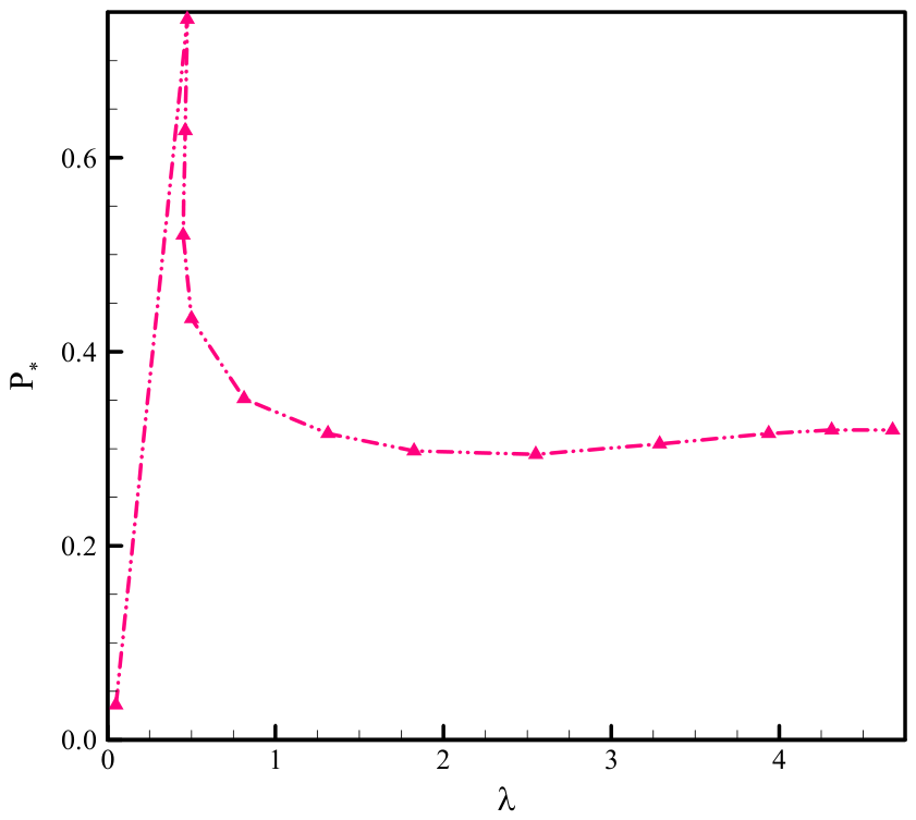
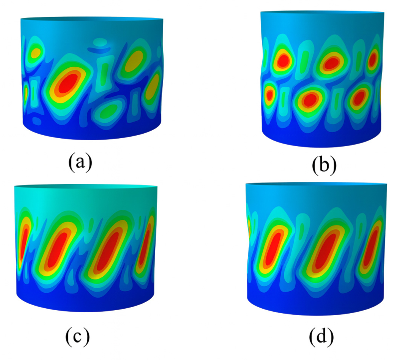
Figure 8, Figure 9, Figure 10 and Figure 11 examine how the slenderness h/r influences the post-buckling response of the clamped–clamped shell under axial compression as well as an initial twist. With r/t fixed at 150, h/r takes values 0.50, 1.25, 1.75, and 2.25. A pre-torsion of T0 = 0.3 Tcr0 is applied, which lowers the buckling load at onset by about 32 percent relative to pure compression. As h/r increases, additional series terms are needed for Galerkin convergence, which raises computational cost; therefore, the main discussion focuses on shorter shells, with FEA for somewhat longer ones. For a very short shell (h/r = 0.5), as shown in Figure 8, FEA indicates an immediate snap after buckling into a diagonal pattern when compressed with pre-torsion. For longer shells (L/r = 0.75, 1.25, and 2.25), as illustrated in Figure 9, Figure 10 and Figure 11, the post-buckling response is largely compression-dominated: the structure jumps between successive modes as the circumferential wavenumber decreases stepwise. The buckled shapes of the shell corresponding Figure 8, Figure 9, Figure 10 and Figure 11 are displayed in Figure 12. During loading, the pattern evolves from a twisted diamond form to diagonal patterns, in agreement with both the theoretical model and FEA. Cylinders with L/r < 1 can also display this compression-dominated evolution if the imposed pre-torsion is smaller; for example, with r/t = 150, h/r = 0.75, and T0 = 0.10 Tcr0, the shape changes from twisted diamond to diagonal.

4. Conclusions

This study comprehensively examined the buckling characteristics of thin cylindrical shells subjected to combined torsional and axial loading through theoretical modeling and finite element simulations. Three loading scenarios were analyzed, torsion and pre-tension, compression with pre-torsion and torsion with pre-compression, alongside the pure torsion and pure compression cases. The results highlight the strong coupling between torsion and compression: pre-torsion reduces the buckling load, modifies the circumferential wavenumber, and governs the transition of post-buckling modes from diamond to diagonal morphologies. Furthermore, increasing shell slenderness promotes multi-snap behavior, whereas high pre-torsion suppresses mode switching and stabilizes deformation. Theoretical analysis employed Donnell’s shell theory combined with the Galerkin method to determine critical loads, wavenumbers, and post-buckling paths. Predictions aligned well with FE results. Key conclusions include the following:
  • The critical buckling pattern is highly sensitive to shear stresses from torsion, even when small compared to compressive stresses, often inducing diagonal buckling patterns.
  • With low pre-torsion, the shell sequentially snaps between modes with decreasing wavenumbers, transitioning from twisted diamond to diagonal patterns. High pre-torsion leads to direct diagonal buckling with no further snapping.
  • Pre-tension enhances torsional buckling resistance and stabilizes post-buckling paths, with no snapping observed.
  • High pre-compression induces snapping and a mode transition from diagonal to twisted diamond patterns.
These findings emphasize the influence of torsion–axial coupling on the instability of thin shells and may inform the design of adaptive or foldable cylindrical shell structures. The results also highlight the necessity of advanced shell theories for thicker or longer shells where shear and edge effects become significant.
As a prospective extension of this research, future work will focus on the buckling and post-buckling behavior of cylindrical shells reinforced with stiffening rings under coupled axial–torsional loadings. Given that ring stiffeners are widely used in structural and aerospace engineering to enhance the load-carrying capacity and stability of thin-walled shells, extending the present analytical framework to account for stiffener spacing, geometry, and placement will provide valuable practical insights.

Author Contributions

Conceptualization, N.F. and N.M.; methodology, N.F. and N.M.; software, N.F.; validation, N.F. and N.M.; formal analysis, N.F. and N.M.; investigation, N.M.; resources, N.M.; data curation, N.M.; writing—original draft preparation, N.F.; writing—review and editing, N.M.; visualization, N.M.; supervision, N.F.; project administration, N.M.; funding acquisition, N.M. All authors have read and agreed to the published version of the manuscript.

Funding

This work was supported and funded by the Deanship of Scientific Research at Imam Mohammad Ibn Saud Islamic University (IMSIU) (grant number: IMSIU-DDRSP2603).

Data Availability Statement

Data will be available upon request from the authors. The data are not publicly available due to privacy.

Acknowledgments

We acknowledge support for the publication costs by the Open Access Publication Fund of Bauhaus Universität Weimar and the Deutsche Forschungsgemeinschaft (DFG).

Conflicts of Interest

The authors declare no conflicts of interest.

Nomenclature

SymbolDefinition
αpModal coefficient associated with the p-th mode
βCoefficient used in the Galerkin formulation
Am,j, Bm,jGalerkin integral coefficients
am, am,nGalerkin expansion coefficients
DFlexural stiffness of the cylindrical shell
EYoung’s modulus
ψAiry stress function
FApplied axial force
h, LAxial length of the cylindrical shell (notation as used in the manuscript)
MNumber of retained terms in the Galerkin series
m, n, p, qInteger modal indices
NCircumferential wavenumber
Nx1, Nx2, Nx1×2In-plane membrane-force resultants
FApplied axial load; F > 0 denotes compression and F < 0 denotes tension
Pcr0Critical buckling load under pure axial compression
rCylinder radius (notation as used in the manuscript)
tShell thickness
TApplied torque
T0Pre-applied torsion
Tcr0Critical buckling torque under pure torsion
u3Transverse (radial) displacement
x 1 , x 2 , x 3 Longitudinal, circumferential, and radial coordinates, respectively
ΔEnd shortening
λNondimensional end shortening
ksShear correction factor
φTwisting angle
νPoisson’s ratio
ϕm, ψm,nAssumed trigonometric modal functions
4Biharmonic operator
AbbreviationDefinition
C–CClamped–clamped
FEAFinite element analysis
SPLASingle perturbation

References

  1. Donnell, L.H. Stability of Thin-Walled Tubes under Torsion. Trans. Am. Soc. Mech. Eng. 1935, 56, 108. [Google Scholar] [CrossRef] [Scilit]
  2. Timoshenko, S.P.; Gere, J.M. Theory of Elastic Stability; Courier Corporation: North Chelmsford, MA, USA, 2012. [Google Scholar]
  3. Weingarten, V.I.; Seide, P.; Peterson, J.P. Buckling of Thin-Walled Circular Cylinders; National Aeronautics and Space Administration: Washington, DC, USA, 1968.
  4. Sun, J.; Zhu, S.; Tong, Z.; Zhou, Z.; Xu, X. Post-buckling analysis of functionally graded multilayer graphene platelet reinforced composite cylindrical shells under axial compression. Proc. R. Soc. A 2020, 476, 20200506. [Google Scholar] [CrossRef] [Scilit]
  5. Hutchinson, J.W. Knockdown factors for buckling of cylindrical and spherical shells subject to reduced biaxial membrane stress. Int. J. Solids Struct. 2010, 47, 1443–1448. [Google Scholar] [CrossRef] [Scilit]
  6. Hutchinson, J.W.; Thompson, J.M.T. Imperfections and energy barriers in shell buckling. Int. J. Solids Struct. 2018, 148, 157–168. [Google Scholar] [CrossRef] [Scilit]
  7. Zhang, X.; Han, Q. Buckling and postbuckling behaviors of imperfect cylindrical shells subjected to torsion. Thin-Walled Struct. 2007, 45, 1035–1043. [Google Scholar] [CrossRef] [Scilit]
  8. Xu, F.; Potier-Ferry, M. On axisymmetric/diamond-like mode transitions in axially compressed core–shell cylinders. J. Mech. Phys. Solids 2016, 94, 68–87. [Google Scholar] [CrossRef] [Scilit]
  9. Yang, Y.; Dai, H.-H.; Xu, F.; Potier-Ferry, M. Pattern transitions in a soft cylindrical shell. Phys. Rev. Lett. 2018, 120, 215503. [Google Scholar] [CrossRef] [Scilit]
  10. Zhao, Y.; Cao, Y.; Feng, X.-Q.; Ma, K. Axial compression-induced wrinkles on a core–shell soft cylinder: Theoretical analysis, simulations and experiments. J. Mech. Phys. Solids 2014, 73, 212–227. [Google Scholar] [CrossRef] [Scilit]
  11. Hunt, G.W.; Ario, I. Twist buckling and the foldable cylinder: An exercise in origami. Int. J. Non-Linear Mech. 2005, 40, 833–843. [Google Scholar] [CrossRef] [Scilit]
  12. Groh, R.M.J.; Pirrera, A. On the role of localizations in buckling of axially compressed cylinders. Proc. R. Soc. A Math. Phys. Eng. Sci. 2019, 475, 20190006. [Google Scholar] [CrossRef] [Scilit]
  13. Kreilos, T.; Schneider, T.M. Fully localized post-buckling states of cylindrical shells under axial compression. Proc. R. Soc. A Math. Phys. Eng. Sci. 2017, 473, 20170177. [Google Scholar] [CrossRef] [Scilit]
  14. Cooley, S.A.; Groh, R.M.J.; Peletier, M.A.; Thompson, J.M.T.; Hutchinson, J.W. Spatial chaos as a governing factor for imperfection sensitivity in shell buckling. Phys. Rev. E 2019, 100, 032205. [Google Scholar] [CrossRef] [Scilit]
  15. Hamad, A.G.; Firouzi, N.; Al Rjoub, Y.S. New insight to large deformation analysis of thick-walled axisymmetric functionally graded hyperelastic ellipsoidal pressure vessel structures: A comparison between FEM and PINNs. Comput. Mater. Contin. 2026, 87, 15. [Google Scholar] [CrossRef] [Scilit]
  16. Firouzi, N.; Tornabene, F.; Wang, J.; Macek, W.; Podulka, P. An Updated Lagrangian framework for large deformation analysis of thin elastomeric materials. Acta Mech. 2025, 236, 4277–4294. [Google Scholar] [CrossRef] [Scilit]
  17. Firouzi, N.; Żur, K.K.; Amabili, M.; Rabczuk, T. On the time-dependent mechanics of membranes via the nonlinear finite element method. Comput. Methods Appl. Mech. Eng. 2023, 407, 115903. [Google Scholar] [CrossRef] [Scilit]
  18. Thompson, J.M.T.; Hutchinson, J.W. Nonlinear buckling interaction for spherical shells subject to pressure and probing forces. J. Appl. Mech. 2017, 84, 121003. [Google Scholar] [CrossRef] [Scilit]
  19. Abramian, A.; Virot, E.; Lozano, E.; Rubinstein, S.M.; Schneider, T.M. Nondestructive Prediction of the Buckling Load of Imperfect Shells. Phys. Rev. Lett. 2020, 125, 225504. [Google Scholar] [CrossRef] [Scilit]
  20. Cuccia, N.L.; Yadav, K.K.; Virot, E.; Gerasimidis, S.; Rubinstein, S.M. Probing at the initiation site allows for accurate prediction of a cylinder’s buckling load. Philos. Trans. R. Soc. A Math. Phys. Eng. Sci. 2023, 381, 20220036. [Google Scholar] [CrossRef] [Scilit]
  21. Sun, W.; Zhu, T.; Qiu, Y.; Lin, G. Buckling load prediction of sparsely stiffened cylindrical shells via non-destructive probing technique. Int. J. Solids Struct. 2023, 276, 112327. [Google Scholar] [CrossRef] [Scilit]
  22. Fan, H.; Li, L.; Gu, W.; Liu, P.; Hu, D. Critical buckling load prediction of axially compressed cylindrical shell based on non-destructive probing method. Thin-Walled Struct. 2019, 139, 91–104. [Google Scholar] [CrossRef] [Scilit]
  23. Fan, H.; Li, L.; Gu, W.; Liu, P.; Hu, D. Buckling design of stiffened cylindrical shells under axial compression based on energy barrier approach. Thin-Walled Struct. 2022, 179, 109667. [Google Scholar] [CrossRef] [Scilit]
  24. Ehrhardt, D.A.; Brink, A.; Kuether, R.J.; Quinn, D.D.; Virgin, L.N. Experiments on Probing the Configuration Space of Post-Buckled Panels. J. Appl. Mech. 2020, 87, 121005. [Google Scholar] [CrossRef] [Scilit]
  25. Chen, X.; Brink, A.; Kuether, R.J.; Quinn, D.D.; Virgin, L.N. Creating Geometric Imperfections in Thin-Walled Shells: An Experimental Protocol. J. Appl. Mech. 2024, 91, 121014. [Google Scholar]
  26. Castro, S.G.P.; Zimmermann, R.; Arbelo, M.A.; Khakimova, R.; Hilburger, M.W.; Degenhardt, R. Geometric imperfections and lower-bound methods used to calculate knock-down factors for axially compressed composite cylindrical shells. Thin-Walled Struct. 2014, 74, 118–132. [Google Scholar] [CrossRef] [Scilit]
  27. Evkin, A.; Lupuleac, S.; Smyshlyaev, P. Local buckling of axially compressed cylindrical shells with different boundary conditions. Thin-Walled Struct. 2019, 141, 374–384. [Google Scholar] [CrossRef] [Scilit]
  28. Wagner, H.N.R.; Hühne, C.; Niemann, S.; Khakimova, R. Robust design criterion for axially loaded cylindrical shells—Simulation and validation. Thin-Walled Struct. 2017, 115, 154–162. [Google Scholar] [CrossRef] [Scilit]
  29. Wagner, H.N.R.; Hühne, C. Towards robust knockdown factors for the design of conical shells under axial compression. Int. J. Mech. Sci. 2018, 146–147, 60–80. [Google Scholar] [CrossRef] [Scilit]
  30. Wagner, H.N.R.; Hühne, C.; Elishakoff, I. Probabilistic and deterministic lower-bound design benchmarks for cylindrical shells under axial compression. Thin-Walled Struct. 2019, 146, 106451. [Google Scholar] [CrossRef] [Scilit]
  31. Jiao, P.; Li, X.; Xu, H.; Chen, Z. Buckling behaviors of thin-walled cylindrical shells under localized axial compression loads: Numerical study. Compos. Struct. 2021, 277, 114616. [Google Scholar]
  32. Jiao, P.; Li, X.; Xu, H.; Chen, Z. Buckling analyses of thin-walled cylindrical shells subjected to multi-region localized axial compression: Experimental and numerical study. Thin-Walled Struct. 2022, 183, 110330. [Google Scholar] [CrossRef] [Scilit]
  33. Ma, W.; Chen, X.; Wang, D.; Tan, Y.; Xie, S.; Xiao, Z. Buckling behaviors of composite cylindrical shells under external hydrostatic pressure. Metals 2023, 13, 564. [Google Scholar]
  34. Gliszczynski, A.; Kubiak, T.; Rzeszut, K. Analytical Study on the Buckling of Cylindrical Shells with Circumferentially Variable Thickness Under Nonuniform External Pressure. J. Press. Vessel Technol. 2024, 146, 041301. [Google Scholar] [CrossRef] [Scilit]
  35. Lu, L.; Leanza, S.; Liu, Y.; Zhao, R.R. Buckling and post-buckling of cylindrical shells under combined torsional and axial loads. Eur. J. Mech. A Solids 2025, 112, 105653. [Google Scholar] [CrossRef] [Scilit]
  36. Zhang, J.; Du, Y.; Chen, Y.; Lu, J.; Zhao, Q.; Ullah, S.; Li, R. A novel unified solution framework for free vibration of non-Lévy-type porous FGM plates. Thin-Walled Struct. 2025, 6, 114215. [Google Scholar] [CrossRef] [Scilit]
  37. Zhang, J.; Du, Y.; Liu, H.; Ullah, S.; Zhao, Q.; Qi, W.; Chen, W. A straightforward analytical method for buckling problems of Mindlin plates with complex boundary conditions. Structures 2025, 81, 110330. [Google Scholar] [CrossRef] [Scilit]
  38. Zhang, J.; Du, Y.; Zhao, Q.; Lu, J.; Abbasi, T.U.R.; Ullah, S.; Chen, W. Free vibration solutions of functionally graded plates with various boundary conditions using unified finite integral transform approach. Eng. Struct. 2025, 341, 120788. [Google Scholar] [CrossRef] [Scilit]
  39. An, D.; Xu, J.; Chen, Y.; Wang, C.; Wang, B.; Li, R. Straightforward free vibration solutions of open cylindrical shells by the finite integral transform method. Int. J. Struct. Stab. Dyn. 2024, 24, 2450097. [Google Scholar] [CrossRef] [Scilit]
  40. Zhang, J.; Zhao, Q.; Ullah, S.; Geng, L.; Civalek, Ö. A new analytical solution of vibration response of orthotropic composite plates with two adjacent edges rotationally-restrained and the others free. Compos. Struct. 2021, 266, 113882. [Google Scholar] [CrossRef] [Scilit]
  41. Chopin, J.; Kudrolli, A. Helicoids, wrinkles, and loops in twisted ribbons. Phys. Rev. Lett. 2013, 111, 174302. [Google Scholar] [CrossRef] [Scilit]
Figure 1. (a) Schematic representation of a cylindrical shell subjected to simultaneous torsional and axial forces. (b) Computational grid.
Symmetry 18 01448 g001
Figure 2. Validation of the numerical buckling results with those of the analytical Galerkin method.
Symmetry 18 01448 g002
Figure 3. Variation in the normalized compressive load with end shortening for the post-buckling response of clamped–clamped shell characterized by (r/t = 150) and (h = 200 mm) under axial compression with torsion of T0 = 0.
Symmetry 18 01448 g003
Figure 4. Variation in the normalized compressive load with end shortening for the post-buckling response of clamped–clamped shell characterized by (r/t = 150) and (h = 200 mm) under axial compression with torsion of T0 = 0.30 Tcr0.
Symmetry 18 01448 g004
Figure 5. The buckled configuration for four different torsions (a) T0 = 0, (b) T0 = 0.30 Tcr0, (c) T0 = 0.60 Tcr0, (d) T0 = 0.80 Tcr0. In all cases, r/t = 150 and h = 200 mm.
Symmetry 18 01448 g005
Figure 6. Variation in the normalized compressive load with end shortening for the post-buckling response of clamped–clamped shell characterized by (r/t = 150) and (h = 200 mm) under axial compression with torsion of T0 = 0.6 Tcr0.
Symmetry 18 01448 g006
Figure 7. Variation in the normalized compressive load with end shortening for the post-buckling response of clamped–clamped shell characterized by (r/t = 150) and (h = 200 mm) under axial compression with torsion of T0  = 0.8 Tcr0.
Symmetry 18 01448 g007
Figure 8. Curve of P -λ describing the post-buckling response of clamped–clamped cylinders with r/t = 150 subjected to axial compression and a pre-torsion T0 = 0.3 Tcr0 for h/r value = 0.5.
Symmetry 18 01448 g008
Figure 9. Curve of P -λ describing the post-buckling response of clamped–clamped cylinders with r/t = 150 subjected to axial compression and a pre-torsion T0 = 0.3 Tcr0 for h/r value = 0.75.
Symmetry 18 01448 g009
Figure 10. Curve of P -λ describing the post-buckling response of clamped–clamped cylinders with r/t = 150 subjected to axial compression with a pre-torsion T0 = 0.3 Tcr0 for h/r value = 1.25.
Symmetry 18 01448 g010
Figure 11. Curve of P -λ describing the post-buckling response of clamped–clamped cylinders with r/t = 150 under axial compression with a pre-torsion T0 = 0.3 Tcr0 for h/r value = 2.25.
Symmetry 18 01448 g011
Figure 12. Buckled configuration for four different values of h/r: (a) 0.5 (b) 0.75 (c) 1.25 (d) 2.25. In all cases, T0 = 0.3 TCR0.
Symmetry 18 01448 g012
Disclaimer/Publisher’s Note: The statements, opinions and data contained in all publications are solely those of the individual author(s) and contributor(s) and not of MDPI and/or the editor(s). MDPI and/or the editor(s) disclaim responsibility for any injury to people or property resulting from any ideas, methods, instructions or products referred to in the content.