Article

Comparison of AFIR NS and AFIR NN Topologies Using the Magnetic Equivalent Circuit Method

1
Department of Electrical-Electronics Engineering, Marmara University, Istanbul 34854, Türkiye
2
Department of Electrical Electronics Engineering, Istanbul Topkapı University, Istanbul 34087, Türkiye
3
Department of Electronic and Automation, Ankara University, Ankara 06100, Türkiye
4
Department of Electrical and Energy, Osmaniye Korkut Ata University, Osmaniye 80750, Türkiye
5
Department of Mechatronics, Ataşehir Adıgüzel Vocational School, Istanbul 34779, Türkiye
*
Author to whom correspondence should be addressed.
Symmetry 2026, 18(8), 1256; https://doi.org/10.3390/sym18081256
Submission received: 29 June 2026 / Revised: 13 July 2026 / Accepted: 19 July 2026 / Published: 24 July 2026
(This article belongs to the Section F: Engineering and Materials)

Abstract

This study presents a comparison of Double Stator Single Rotor Axial Flux Inner Rotor North–South (DSSR AFIR NS) and Double Stator Single Rotor Axial Flux Inner Rotor North–North (DSSR AFIR NN) configurations based on the magnetic equivalent circuit (MEC) approach. In the first stage, a magnetic equivalent circuit model of the DSSR AFIR NS topology was developed, and the mathematical formulations of the air-gap reluctance, stator tooth reluctance, stator yoke reluctance, and rotor core reluctance constituting the magnetic flux path were derived. Considering the motor’s geometric and electromagnetic characteristics, the magnetic flux and flux density distributions in each region were analytically evaluated. The obtained results were then validated through finite element analysis (FEA). In the second stage, the DSSR AFIR NN topology was investigated using the same methodology, and the electromagnetic performances of the two machines with identical slot numbers, pole numbers, and physical dimensions were compared to determine their respective advantages and limitations. Numerical analyses show the AFIR-NN topology yields higher torque (26.53 Nm) than AFIR-NS (19.43 Nm). Conversely, AFIR-NS exhibits superior magnetic characteristics, with higher back-EMF (34.73 V vs. 19.37 V) and air-gap flux density (0.89 T vs. 0.46 T).

1. Introduction

Axial flux permanent magnet (AFPM) motors, which have been intensively investigated by electrical machine designers in recent years, are highly preferred in applications such as renewable energy systems and electric vehicles. Typically, these machines are manufactured in four distinct topological configurations: single-stator single-rotor (SSSR), single-stator double-rotor (SSDR), double-stator single-rotor (DSSR) AFPM [1,2], and multiple stator-multiple rotor (MSMR) AFPM motors [3].
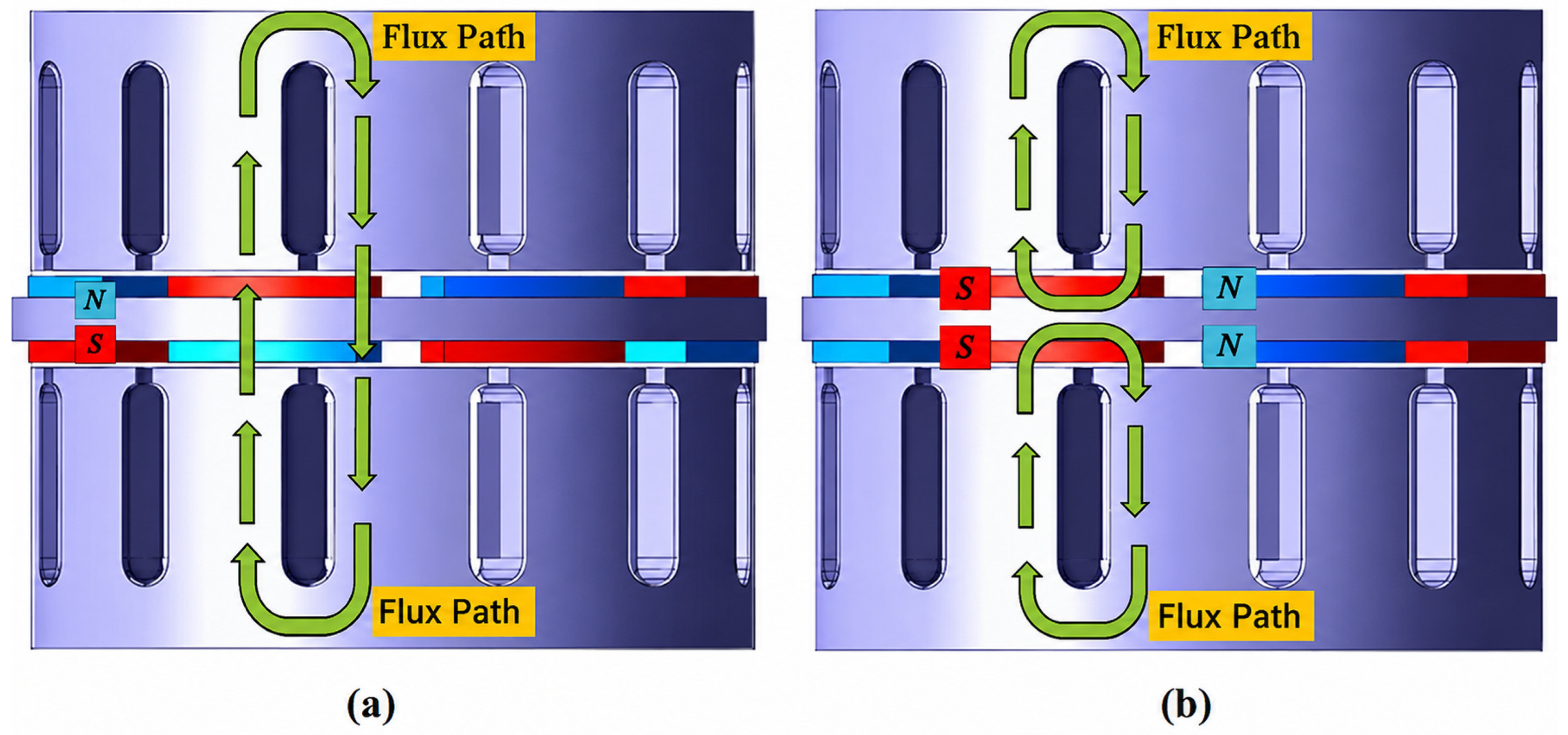
The SSSR topology is utilized in the transportation sector due to its high torque capability. In this configuration, unbalanced forces induced by the axial forces between the stator and the rotor can lead to noisy and vibrant operation in the motor [3,4]. DSSR-type axial flux permanent magnet (AFPM) motors consist of two stators and an internally positioned rotor. In this configuration, the permanent magnets can be either surface-mounted or interior-embedded. In addition to topologies featuring a rotor core that supports the permanent magnets, there are also coreless configurations where the magnets are sustained by non-magnetic materials such as aluminum or plastic in order to reduce the weight and inertia of the rotating assembly [5,6,7]. Furthermore, motors in the DSSR topology can be configured as axial flux internal rotor (AFIR) NS or AFIR NN types. The key distinction between these configurations is determined by the magnetic flux path. In the AFIR-NS structure, the flux emerging from the first stator passes through the air gap and the rotor axially to reach the second stator, thereby completing its circuit. Conversely, in the AFIR-NN type, the flux arriving from the stator deflects tangentially within the rotor yoke and loops back to reach the same stator to complete its path [8]. SSDR-type AFPM motors consist of two rotors and an internally positioned stator. Due to its symmetrical geometry, the impact of unbalanced axial forces is significantly lower in the SSDR configuration, thereby minimizing the adverse effects of vibrant operation and associated mechanical issues [9]. In applications requiring high torque density, multi-stage configurations that incorporate one more rotor than the number of stators aiming to increase torque without expanding the outer machine diameter are designated as MSMR AFPM motors [3,10].
Concentric winding structures are preferred for stator windings to achieve a uniform magnetic field distribution and to provide structural simplicity. This winding topology is commonly utilized in applications that require a constant speed. Conversely, in applications demanding high efficiency and precise speed control, the double-layer winding method is widely preferred. Axial flux machines in the SSDR (Single-Stator Double-Rotor) configuration are frequently proposed for electric vehicle applications due to their balanced net magnetic pull, which minimizes axial bearing loads. In this topology, the winding structure can be designed in a concentric or toroidal shape; machines featuring this specific winding and core architecture are referred to as TORUS-type in the literature [3,11]. Furthermore, there are YASA (Yokeless and Segmented Armature)-type axial flux permanent magnet machines, which utilize concentrated windings without a magnetic stator yoke. Due to the elimination of stator iron losses, YASA-type machines exhibit superior performance in terms of efficiency and power density compared to the TORUS configuration [12].
The design and optimization of electrical machines are generally carried out using finite element analysis (FEA). However, this method typically requires long computational times due to its intensive processing requirements and high computational costs [13]. In the Magnetic Equivalent Circuit (MEC) method, each geometric region of the electrical motor is represented by a magnetic reluctance, and the machine performance is analytically predicted using the principles applied in electrical circuit analysis [14,15,16].
The primary motivation of this study is to investigate the effects of pole configurations on machine performance in axial flux permanent magnet synchronous motors through both theoretical and numerical methods. For this purpose, the DSSR AFIR NS and DSSR AFIR NN topologies, which are widely utilized in literature but exhibit fundamental differences in terms of magnetic flux behavior, are subjected to a comprehensive comparative analysis based on the Magnetic Equivalent Circuit (MEC) approach. The organization of the remainder of this paper is structured as follows: In Section 2, the analytical MEC model of the DSSR AFIR NS topology is presented, and the mathematical formulations for the air-gap, stator tooth, stator yoke, and rotor core reluctances constituting the magnetic flux path are derived. The obtained analytical flux and flux density distributions are validated via three-dimensional finite element analysis (FEA) in Section 3. In Section 4, the same analytical and numerical methodology is applied to the DSSR AFIR NN topology; subsequently, the electromagnetic performances of both machines sharing identical geometric dimensions and slot–pole combinations are compared alongside their respective advantages and limitations. Finally, Section 5 concludes the paper with a summary of the main findings and future design recommendations. Although AFIR-NS and AFIR-NN topologies are widely used in AFPM motor design, studies comparing their electromagnetic characteristics by integrating MEC and FEA approaches are quite limited in the literature. Existing research generally focuses on a single topology or examines these configurations in isolation under different operating conditions. This study addresses this gap by modeling the performance differences between these topologies through a direct MEC-based comparative analysis. The magnetic flux paths for the AFIR NS and AFIR NN configurations are illustrated in Figure 1a and Figure 1b, respectively.

2. Materials and Methods

2.1. Development of the AFIR NS Magnetic Equivalent Circuit

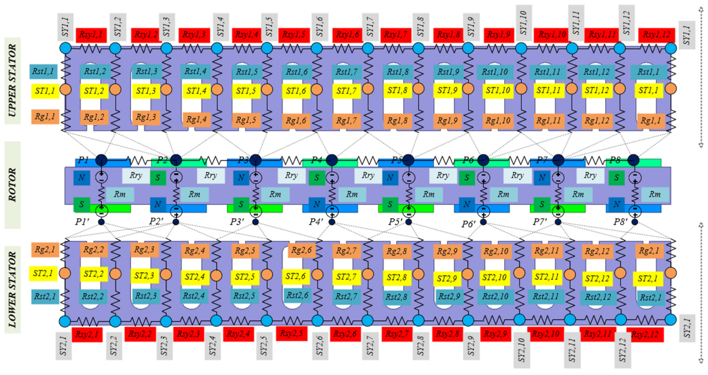
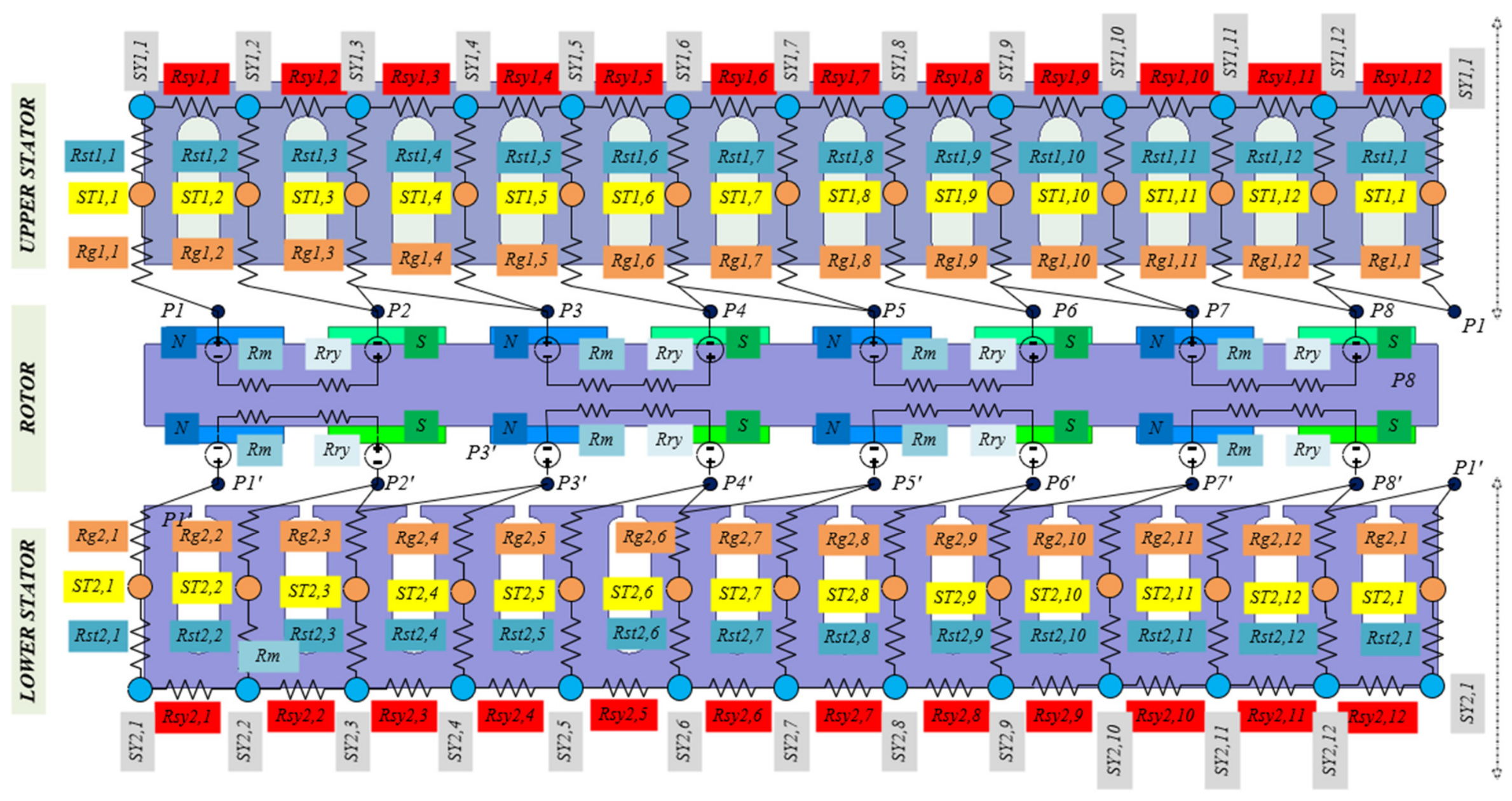
The 2D model of a 12-slot, 8-pole DSSR AFPM (Dual-Stator Axial Flux Permanent Magnet) motor was developed using the magnetic equivalent circuit (MEC) method with ANSYS Maxwell software 2022 R1 version, and the flux behavior under the NS pole configuration was investigated. According to the MEC structure presented in Figure 2, the magnetic flux originating from the upper stator crosses the upper air gap and reaches the magnets and the rotor. Subsequently, it passes through the rotor core to the lower air gap and enters the lower stator yoke. Thus, the flux completes its magnetic circuit by following the path of lower stator–lower air gap–rotor–upper air gap–upper stator.
The nodes in the upper stator yoke are represented by the indices SY1,1 through SY1,12. The reluctances between Rst1,1 and Rst1,12 denote the upper stator tooth reluctances, while the nodes between ST1,1 and ST1,12 represent the magnetic potential nodes within these teeth. The reluctances from Rg1,1 to Rg1,12 correspond to the air gap reluctances. The nodes on the upper side of the rotor are indicated by the P1–P8 range; the rotor reluctance is represented by Rry, and the magnet reluctance is denoted by Rm. The nodes on the lower side of the rotor are designated as P1′–P8′. A similar labeling and definition process has been implemented for the lower stator structure.
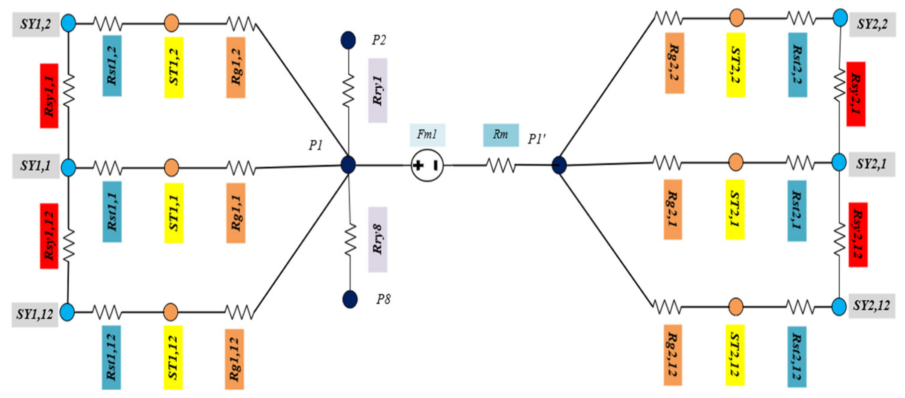
As illustrated in Figure 2, the upper stator comprises 12 nodes for the yoke and 12 nodes for the teeth, with a corresponding set of 24 nodes for the lower stator. Furthermore, 16 nodes are defined for the rotor, with 8 nodes for each of its upper and lower surfaces, resulting in a total of 64 nodes for the entire machine. Formulating the reluctance equations for each node necessitates the construction of a 64 × 64 matrix. However, representing the magnetic equivalent circuit (MEC) for a single pole rather than the entire machine significantly simplifies the computational process and provides substantial time efficiency. The MEC structure for a single pole is presented in Figure 3.
The reluctance expressions for each section are presented in Equations (1)–(6).
R r y = l r y μ 0 μ r , r y A r y
l r y denotes the axial length of the rotor core, μ 0 represents the permeability of free space (air gap permeability), μ r , r y stands for the relative magnetic permeability of the rotor material, and A r y defines the magnetic cross-sectional area of the rotor core.
R m = l m μ 0 μ r , m a g A m
l m denotes the axial length of the magnet, μ r , m a g stands for the relative magnetic permeability of the magnet, and A m defines the magnetic cross-sectional area of the magnet.
R g 1 = g 1 μ 0 A g 1
g 1 denotes the length of the upper air gap, while A g 1 represents the upper cross-sectional area of the air gap.
R g 2 = g 2 μ 0 A g 2
g 2 denotes the length of the lower air gap, while A g 2 represents the lower cross-sectional area of the air gap.
R s t = h s t μ 0 μ r , s t A s t
h s t denotes the height of the stator tooth, μ r , s t represents the relative magnetic permeability of the stator tooth material, and A s t defines the magnetic cross-sectional area of the stator tooth.
R s y = h s y μ 0 μ r , s y A s y
h s y denotes the height of the stator yoke, μ r , s y represents the relative magnetic permeability of the stator yoke material, and A s y defines the magnetic cross-sectional area of the stator yoke. The definition of magnetic permeance is expressed by Equation (7).
G = 1 R
The magnetic node potentials in the equivalent circuit are defined as follows: ( U 1 = U P 1 , U 2 = U P 2 , U 3 = U P 8 , U 4 = U S T 1 , 1 , U 5 = U S T 1 , 2 , U 6 = U S T 1 , 12 , U 7 = U S Y 1 , 1 , U 8 = U S Y 1 , 12 , U 9 = U P 1 ′ , U 10 = U S T 2 , 1 , U 11 = U S T 2 , 2 , U 12 = U S T 2 , 12 , U 13 = U S Y 2 , 1 , U 14 = U S Y 2 , 2 ).
Based on the principle that the sum of the magnetic flux entering a node is zero (KCL), the reluctance equation for the P1 node is defined as shown in Equation (8):
U 1 − U 2 G r y 1 + U 1 − U 3 G r y 8 + U 1 − U 4 G g 1 , 1 + U 1 − U 6 G g 1 , 12 + U 1 − U 5 G g 1 , 2 + U 1 − U 9 G m 1 = 0
The P1′ node can be expressed by Equation (9).
U 9 − U 1 G m 1 + U 9 − U 10 G g 2 , 1 + U 9 − U 11 G g 2 , 2 + U 9 − U 12 G g 2 , 12 = 0
P2 node:
U 2 − U 1 G r y 1 = 0
P8 node:
U 3 − U 1 G r y 8 = 0
ST1,12 node:
U 6 − U 7 G S T 1 , 12 + U 6 − U 1 G g 1 , 12 = 0
ST1,1 node:
U 4 − U 7 G S T 1 , 1 + U 4 − U 1 G g 1 , 1 = 0
ST1,2 node:
U 5 − U 8 G S T 1 , 2 + U 5 − U 1 G g 1 , 2 = 0
ST2,12 node:
U 12 − U 13 G S T 2 , 12 + U 12 − U 9 G g 2 , 12 = 0
ST2,1 node:
U 10 − U 13 G S T 2 , 1 + U 9 − U 9 G g 2 , 1 = 0
ST2,2 node:
U 11 − U 14 G S T 2 , 2 + U 11 − U 9 G g 2 , 2 = 0
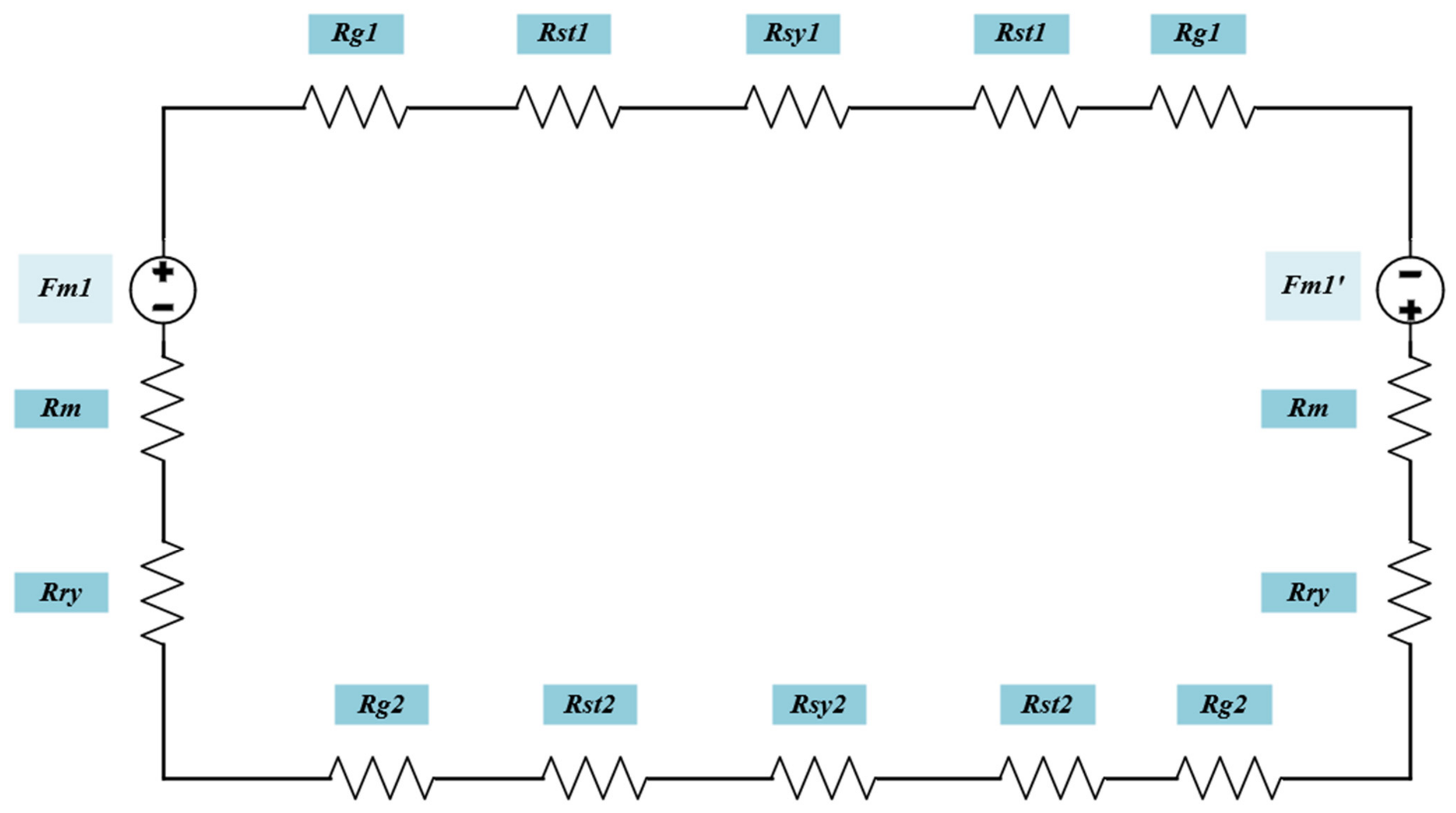
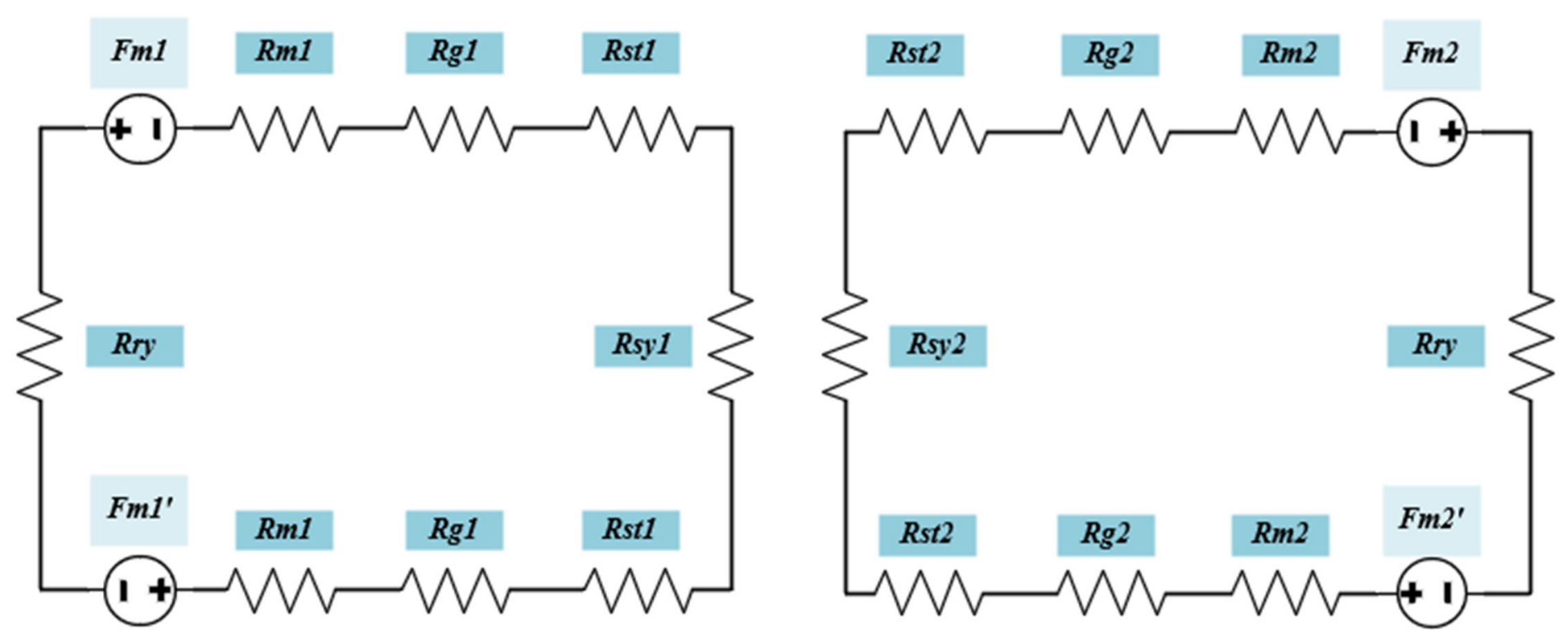
This 10-node network repeats periodically across all 8 poles of the machine. Following the development of the comprehensive magnetic equivalent circuit (MEC) model representing the entire magnetic structure of the machine, this model has been reduced to a single-pole representation to facilitate the analytical solution process. Accordingly, the simplified circuit model, derived by leveraging the machine’s inherent symmetry, has been reconstructed to minimize computational overhead. The schematic representation of this simplified model, specifically developed for the single-pole structure, is presented in Figure 4.
The magnetic equivalent circuit structure shown in the figure can be solved using the analogy of Kirchhoff’s Voltage Law (KVL) from electrical circuits. According to this principle, the total magnetomotive force ( F t ) in a magnetic circuit is equal to the sum of the magnetomotive force drops across the reluctances. The two sources in the circuit are connected in series.
F t = F m 1 + F m 1 ′
Since the circuit is configured in a series structure, the equivalent reluctance is obtained by the summation of all individual reluctances.
R e q = 2 R m + R r y + R g 1 + R g 2 + R s t 1 + R s t 2 + R s y 1 + R s y 2
The magnetic flux in the magnetic circuit is calculated in accordance with the principle of Ohm’s law for magnetic circuits.
∅ = F t R e q = F m 1 + F m 1 ′ 2 R m + R r y + R g 1 + R g 2 + R s t 1 + R s t 2 + R s y 1 + R s y 2

2.2. Development of the AFIR NN Magnetic Equivalent Circuit

In the AFIR-NN topology, the magnetic fluxes in the two stators are not coupled; the flux originating from a stator and reaching the rotor returns to the same stator. This dual-stator configuration consists of two symmetric magnetic circuits. In this model, the flux path starting at node P1 follows the sequence of rotor yoke reluctance (Rry), magnet reluctance (Rm), node P2, air-gap reluctance (Rg1,2), stator tooth reluctance (Rst1,2), stator yoke reluctance (Rsy1,1), and stator tooth reluctance (Rst1,1), finally returning to node P1 to complete the circuit.
The procedures implemented in Section 2.1 were similarly applied to the AFIR-NN topology, and the magnetic flux behavior within the machine was analyzed using the established model as a reference. To avoid redundancy, the reluctance expressions for each section of the machine are not explicitly restated in the text. The governing equations were derived based on Kirchhoff’s Magnetic Circuit Law, ensuring that the sum of the magnetic fluxes entering and leaving each node is equal to zero. Figure 5 presents the AFIR NN MEC structure.
Figure 6 presents the simplified magnetic equivalent circuit of the DSSR AFIR-NN topology. The model consists of two symmetrical circuits corresponding to the upper and lower stator structures.
The total reluctance for the upper stator is expressed by Equation (21).
R e q = 2 R m 1 + R g 1 + R s t 1 + R s y 1 + R r y
Accordingly, the total flux obtained for the upper stator can be expressed by Equation (22). Similarly, the flux equation for the lower stator can be formulated accordingly.
∅ = F t R e q = F m 1 + F m 1 ′ 2 R m 1 + R g 1 + R s t 1 + R s y 1 + R r y

3. Results

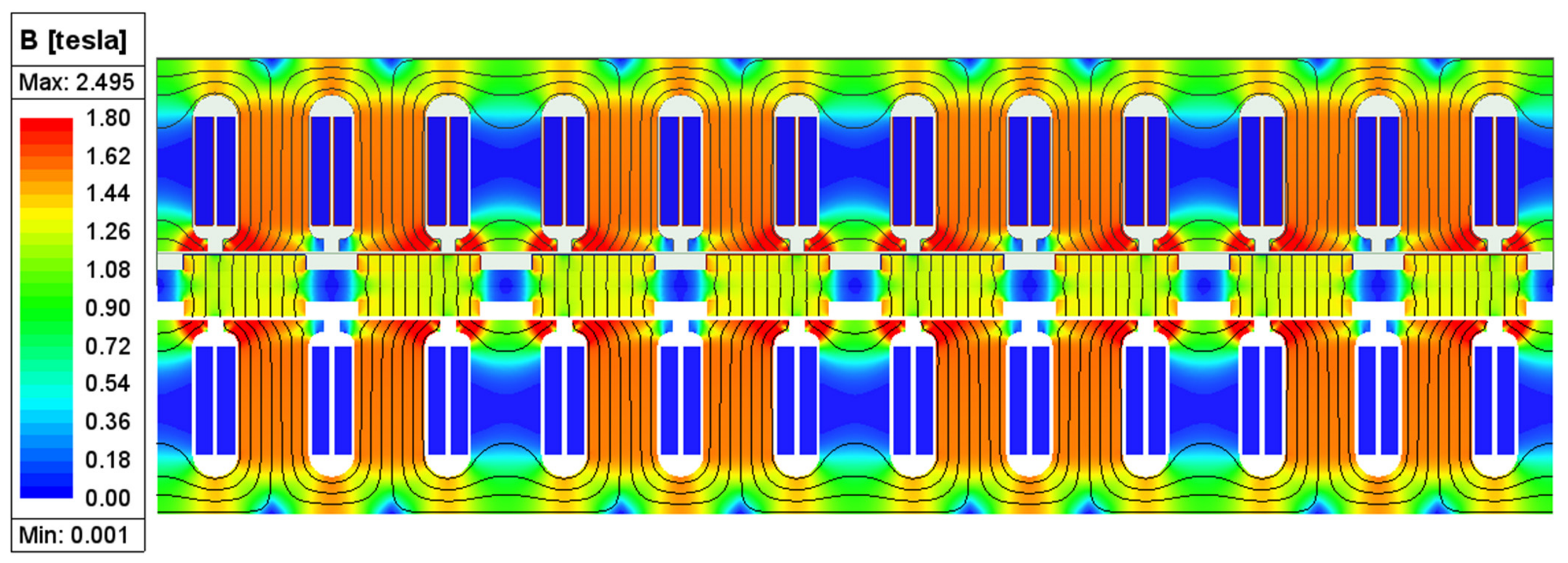
In this section, the AFIR-NS and AFIR-NN topologies are subjected to magnetostatic and transient analyses using ANSYS Maxwell software 2024 R1 version. Through these simulations, the accuracy of the analytically calculated magnetic flux density values is verified. Furthermore, the AFIR-NS and AFIR-NN motor structures, designed with identical parameters, are comparatively investigated in terms of magnetic performance, torque characteristics, and back electromotive force (Back-EMF) profiles. To validate the accuracy of the proposed MEC model, the electromagnetic performance of the motor was simulated using 2D finite element analysis via ANSYS Maxwell. The magnetic flux density and potential values derived from the MEC approach were compared against the FEA simulation results. During this verification process, the deviation rates between the two methods were calculated to determine the model’s accuracy across various load and saturation levels. Furthermore, the model’s capability to capture local saturation effects—particularly within the stator teeth and yoke regions—was verified by comparing it with the flux density maps generated by FEA. The results demonstrate that the proposed nodal-based MEC model achieves accuracy comparable to FEA while significantly reducing computational costs. Figure 7 illustrates the magnetic flux density distribution of the DSSR AFIR NS topology.
In this study, magnetostatic analysis was performed on a Dual Stator Single Rotor (DSSR) axial flux machine with specified geometric parameters. The primary design dimensions are as follows: stator outer diameter of 150 mm, inner diameter of 80 mm, axial length of 50 mm, stator yoke height of 15 mm, and tooth width of 18 mm. The rotor parameters include an axial length of 8 mm, magnet thickness of 4 mm, magnet radial length of 42.7 mm, pole embrace of 0.7, rotor outer diameter of 164 mm, and inner diameter of 55 mm. M250-35A electrical steel is utilized for the stator cores, while Steel 1010 is employed for the rotor core. Additionally, N52H-type high-performance neodymium magnets are used. The number of conductors per slot is 11, with 10 strands in each conductor. The winding configuration is designed as a double-layer, whole-coiled winding with 2 parallel branches. The simulation setup was configured with a maximum of 10 passes, a 1% error tolerance, a 30% refinement rate per pass, and a non-linear residual target of 0.0001 to ensure solution convergence. Regarding the mesh configuration, a length-based approach was implemented with a maximum element length of 3 mm to optimize computational accuracy.
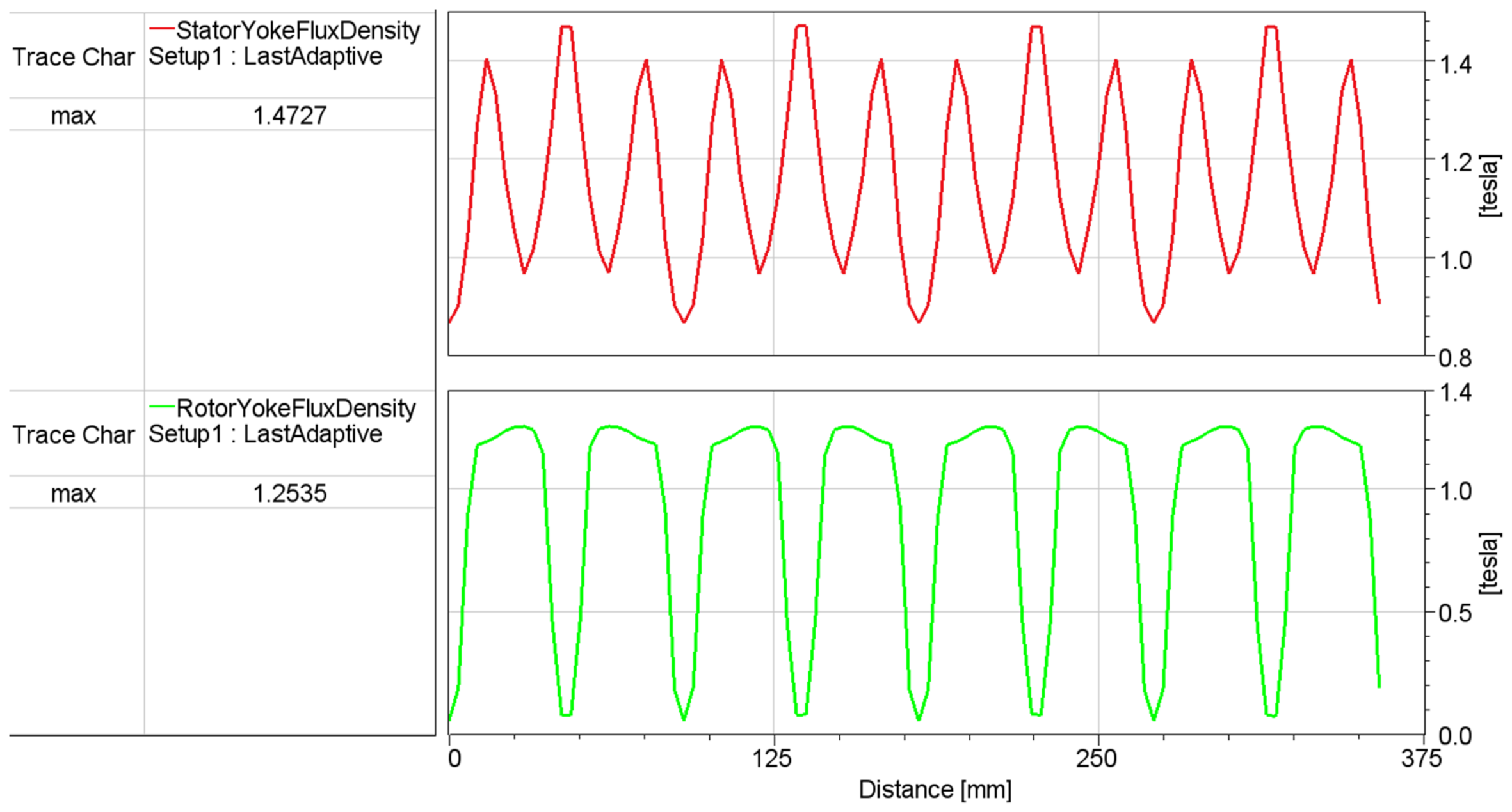
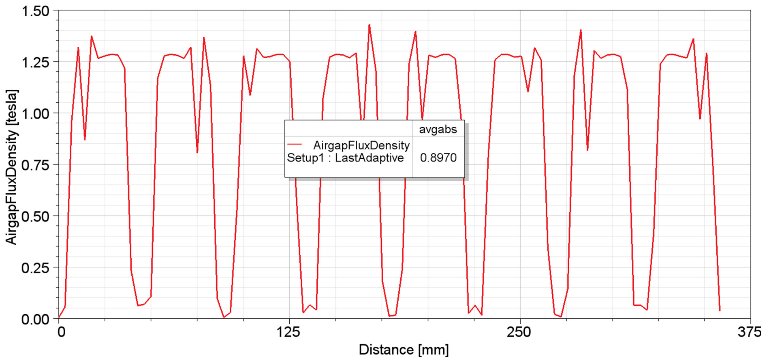
The maximum magnetic flux density in the stator yoke was monitored using a polyline defined at the center of the yoke region (Figure 8). A similar procedure was applied to the rotor core and air-gap regions (Figure 8 and Figure 9). The analysis results demonstrate that the maximum flux density reaches 1.47 T in the stator yoke and 1.25 T in the rotor core. Furthermore, the average magnetic flux density within the air gap was recorded as 0.89 T.
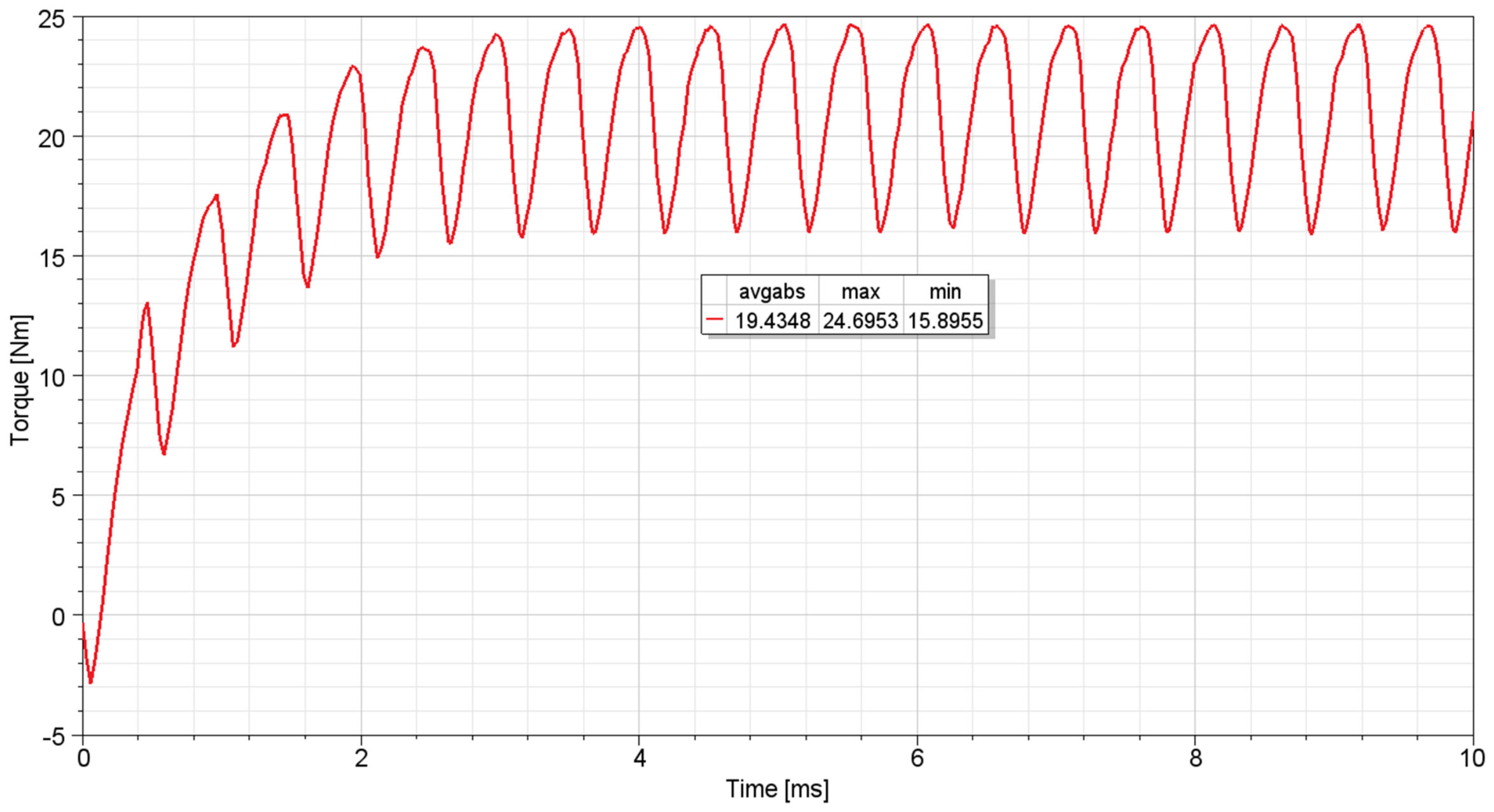
In the transient simulation configuration, the stop time was set to 0.01 s with a time step of 3 × 10⁻⁵ s. The mesh configuration was maintained consistent with the magnetostatic analysis to ensure computational accuracy. The simulation results (Figure 10) indicate an average torque of 19.43 Nm under steady-state operating conditions. Within this operating range, the torque exhibits a ripple profile, peaking at a maximum of 24.69 Nm and reaching a minimum of 15.89 Nm.
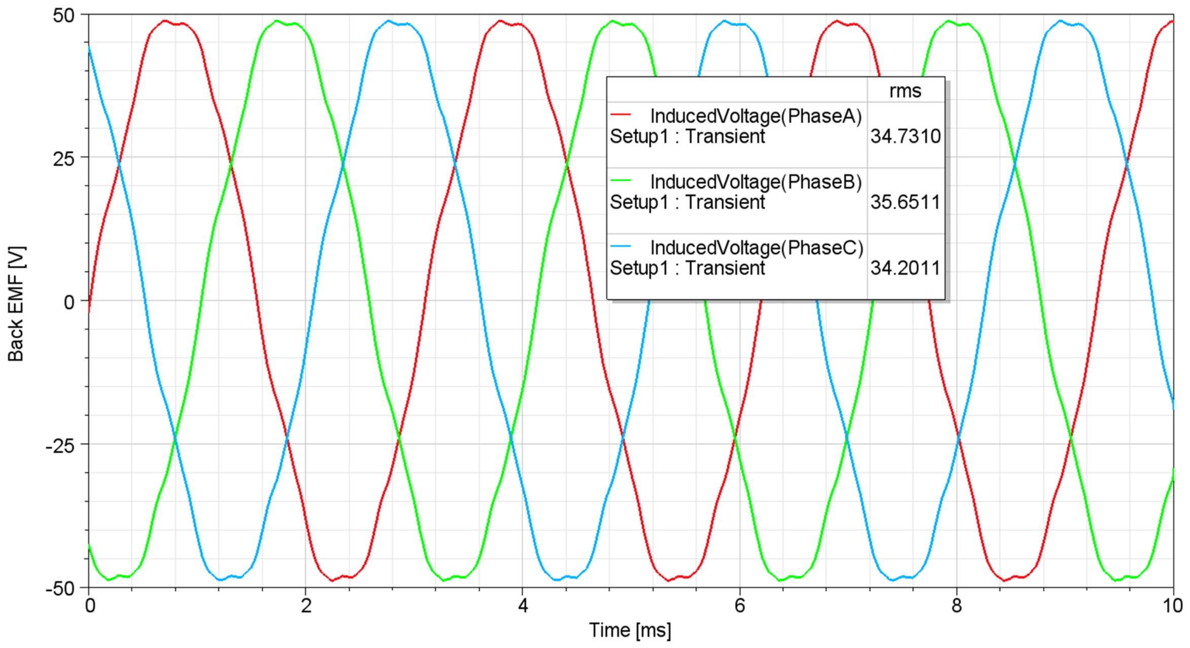
The Back-EMF profiles of the DSSR AFPM motor, simulated according to the 72 V BLDC operating principle, exhibit a trapezoidal waveform. The induced voltage values presented are in RMS format. The analysis results indicate that the induced RMS voltages in the A, B, and C phase windings are 34.73 V, 35.65 V, and 34.20 V, respectively. Figure 11 shows the back-EMF vs. time curve of the AFIR NS structure.
The simulation conditions implemented for the AFIR-NS topology were consistently applied to the AFIR-NN structure. Consequently, the results obtained for both topologies were compared under identical reference parameters, ensuring a fair and consistent performance evaluation.
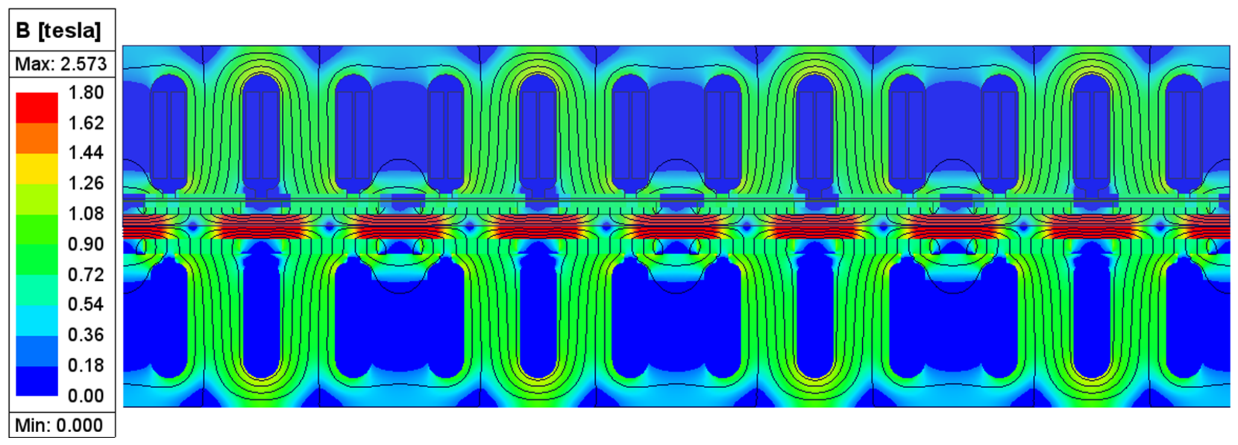
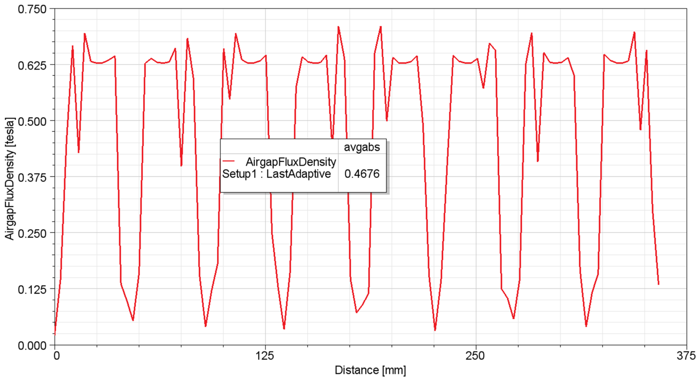
In the AFIR-NN topology, the average air-gap flux density is approximately 0.46 T. As illustrated in Figure 12, there is a significant magnetic flux circulation between adjacent magnets. This phenomenon indicates that a portion of the flux is diverted as inter-pole leakage, thereby reducing the net flux density entering the air gap and effectively diminishing the machine’s magnetic utilization.
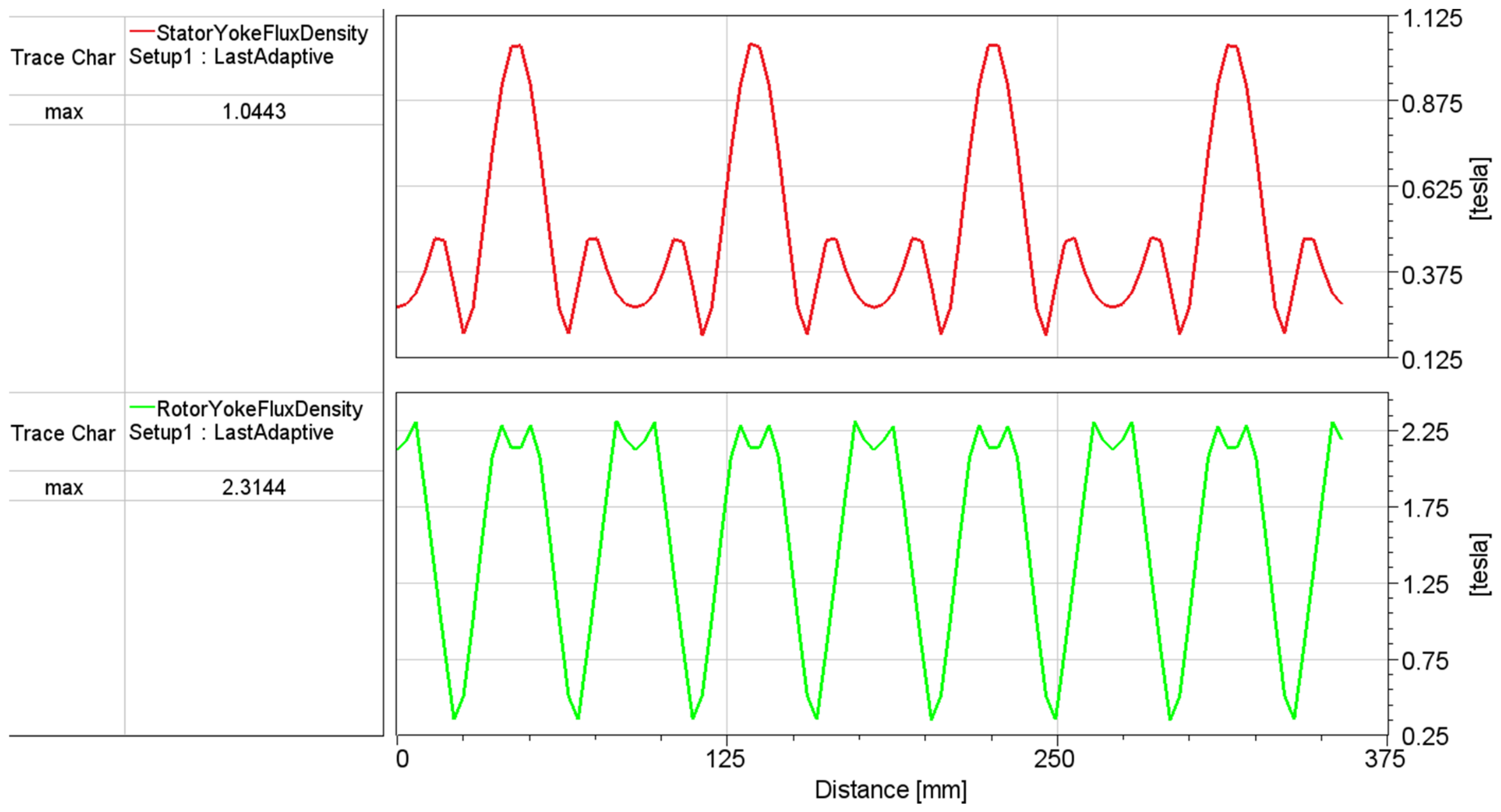
In the AFIR-NN topology, the maximum magnetic flux density is calculated as 1.04 T in the stator yoke and 2.31 T in the rotor core. The magnetic flux path follows a trajectory of upper stator–air gap–rotor core–air gap–upper stator. This magnetic circuit exhibits symmetry for the lower stator as well. Although the rotor core dimensions are identical to those of the NS topology, it accommodates two parallel magnetic circuits, resulting in a reduction in total reluctance. Figure 13 shows the stator yoke flux density and rotor yoke flux density curves of the AFIR NN.
Figure 14 shows the air gap flux density curve for the AFIR NN structure.
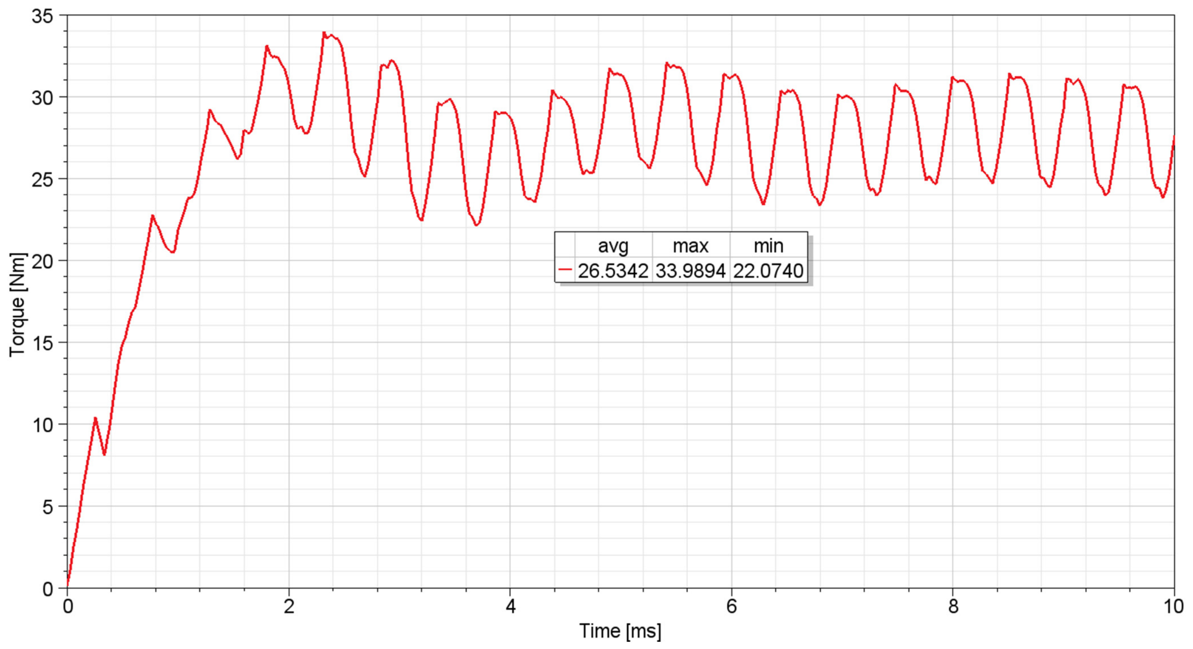
Based on the transient analysis conducted for the AFIR-NN topology (Figure 15), the average torque under steady-state operating conditions was calculated as 26.53 Nm. Within the observed operating range, the torque exhibits a ripple profile, reaching a peak value of 33.98 Nm and a minimum value of 22.07 Nm.
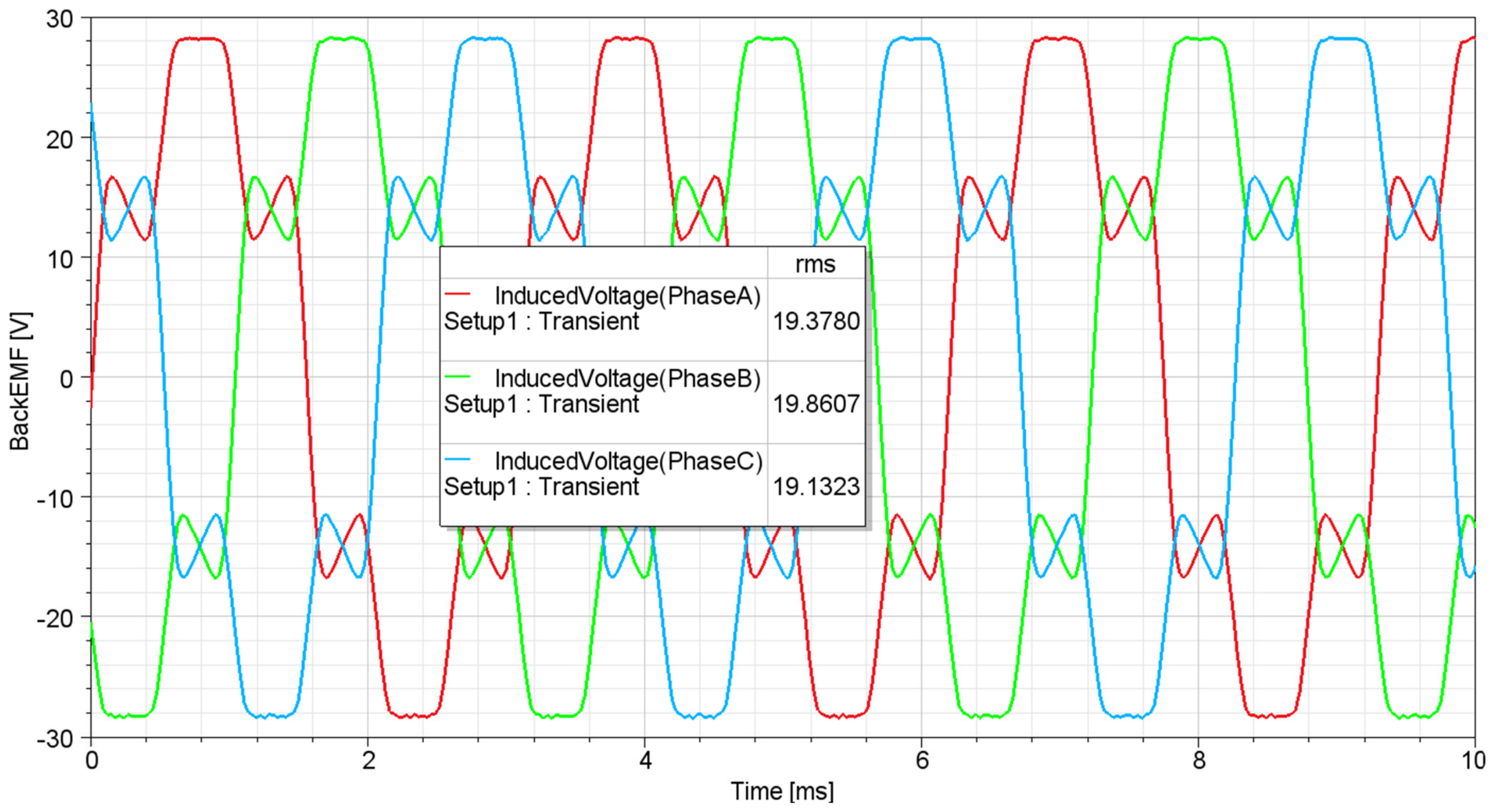
Figure 16 illustrates the time-dependent variation of the induced voltage in the phase windings for the AFIR-NN topology. The analysis results indicate that the observed RMS voltages in the A, B, and C phase windings are 19.37 V, 19.86 V, and 19.13 V, respectively.

4. Discussion

In this study, the performance of AFIR-NS and AFIR-NN topologies was evaluated based on the established MEC model. Our initial working hypothesis suggested that the flux leakage path in the AFIR-NN configuration would significantly impede the stator flux distribution compared to the AFIR-NS type. The results confirm this hypothesis, demonstrating that the NN-type arrangement experiences higher magnetic leakage, particularly within the rotor-to-rotor flux paths, leading to a reduction in the air-gap flux density. These findings are consistent with previous studies [12,17] which indicate that NS-type pole arrangements generally provide a more efficient flux linkage due to the sequential pole transition. Unlike the AFIR-NS structure, which facilitates a continuous magnetic path through the stator teeth, the AFIR-NN topology exhibits short-circuit flux behaviors between adjacent magnets, as illustrated in the developed MEC model (Figure 12).
The comparative analysis indicates a distinct trade-off between the two topologies. The AFIR-NS structure, characterized by higher air-gap flux density and Back-EMF, is better suited for high-speed applications where voltage utilization and flux concentration are critical. Conversely, the AFIR-NN topology, despite higher inter-pole leakage, proves advantageous in high-torque, low-to-medium speed applications. Its ability to achieve higher average torque through symmetric magnetic circuit closure makes it more effective for designs where torque density and structural robustness are prioritized over absolute peak air-gap flux. Furthermore, for applications where leakage control is the primary concern, AFIR-NS is recommended due to its lower inter-pole flux coupling. Consequently, this study suggests that the selection of the optimal topology should be based on a targeted multi-objective optimization approach, where AFIR-NN is favored for torque-intensive tasks and AFIR-NS for voltage-sensitive performance requirements.
The comparative performance of the AFIR-NS and AFIR-NN topologies is presented in Table 1.
The comparison between the MEC and 2D-FEA results presented in Table 2 demonstrates that the proposed model produces consistent results for both topologies. The higher flux density in the rotor yoke for the NN topology confirms our hypothesis that the magnetic flux completes its path symmetrically within the rotor core. The error margins in the air-gap flux density indicate that, in order to achieve more precise results, the leakage flux paths should be modeled in greater detail in future studies.
Although the AFIR-NN topology exhibits a lower peak air-gap flux density compared to the AFIR-NS topology, it demonstrates superior torque production capability. This outcome is attributed to the inherent magnetic circuit symmetry of the NN configuration, which promotes a more uniform and continuous flux linkage across the stator slots. In the AFIR-NN topology, the rotor yoke acts as an active magnetic bridge, enabling a more effective utilization of the magnetic energy in the electromechanical conversion process. Consequently, the interaction between the stator magnetomotive force (MMF) and the rotor field is more effectively maintained throughout the rotation, compensating for the lower air-gap flux density and resulting in a higher average torque output.

5. Conclusions

In this study, the performance characteristics of AFIR-NS and AFIR-NN topologies were analyzed and compared using a developed magnetic equivalent circuit (MEC) model. The comparative results, summarized in Table 1, reveal distinct differences in the electromagnetic behavior of the two configurations:
Torque and Back EMF: While the AFIR-NN topology achieves a higher average torque of 26.53 Nm compared to 19.43 Nm in the AFIR-NS topology, the AFIR-NS configuration demonstrates a superior back EMF performance of 34.73 V, significantly higher than the 19.37 V observed in the AFIR-NN design.
Magnetic Flux Density: The AFIR-NS topology provides a higher air-gap flux density of 0.89 T, nearly doubling the 0.46 T recorded for the AFIR-NN topology. Furthermore, the stator yoke flux density is higher in the AFIR-NS configuration (1.47 T) compared to the AFIR-NN configuration (1.04 T).
Rotor Yoke Behavior: Conversely, the rotor yoke flux density is notably higher in the AFIR-NN topology (2.31 T) than in the AFIR-NS topology (1.25 T), indicating a higher magnetic saturation level in the rotor back-iron for the NN configuration.
In conclusion, these findings demonstrate that while the AFIR-NN topology offers potential for higher torque output, the AFIR-NS configuration exhibits more favorable flux distribution and electromotive force characteristics, making it a more efficient candidate for applications requiring higher back-EMF and air-gap flux density.
This study focuses on the comparative analysis of the electromagnetic performance of AFIR-NS and AFIR-NN topologies using MEC modeling and 2D FEA simulations. A primary limitation of this study is that the simulation findings have not yet been validated through experimental data. Future work will involve the development of a physical prototype to conduct efficiency analyses under various speed and full-load conditions. Furthermore, it is intended to investigate multi-objective optimization processes—considering magnet type, magnet geometry, and rotor core materials—to achieve the best balance among cost, performance, and weight criteria.

Author Contributions

Conceptualization, O.T., T.D. and N.F.O.S.; methodology, O.T., T.D. and N.F.O.S.; software, T.D., V.E. and A.S.S.; validation, O.T., T.D., N.F.O.S. and B.G.; investigation, T.D., A.S.S. and V.E.; writing—original draft preparation, O.T., V.E., T.D., A.S.S., B.G. and N.F.O.S.; writing—review and editing, O.T., V.E., T.D., A.S.S., B.G. and N.F.O.S. All authors have read and agreed to the published version of the manuscript.

Funding

This research received no external funding.

Data Availability Statement

The original contributions presented in this study are included in the article. Further inquiries can be directed to the corresponding author.

Conflicts of Interest

The authors declare no conflicts of interest.

Abbreviations

The following abbreviations are used in this manuscript:
AFPMAxial flux permanent magnet
MECMagnetic equivalent circuit
SSSRSingle-stator single-rotor
SSDRSingle-stator double-rotor
DSSRDouble-stator single-rotor
MSMRMultiple stator-multiple rotor
AFIRAxial flux internal rotor
NSNorth–south
NNNorth–north
FEAFinite element analysis
YASAYokeless and segmented armature
Rst1,1 to Rst1,12Upper stator tooth reluctances
ST1,1 to ST1,12Magnetic potential nodes
Rg1,1 to Rg1,12Air-gap reluctances
P1–P8Nodes on the upper side of the rotor
RryRotor reluctance
RmMagnet reluctance
P1′–P8′Nodes on the lower side of the rotor
l r y Axial length of the rotor core
μ 0 Permeability of free space
μ r , r y Relative magnetic permeability of the rotor material
A r y Magnetic cross-sectional area of the rotor core
l m Axial length of the magnet
μ r , m a g Relative magnetic permeability of the magnet
A m Magnetic cross-sectional area of the magnet
g 1 Length of the upper air gap
A g 1 Upper cross-sectional area of the air gap
g 2 Length of the upper air gap
A g 2 Lower cross-sectional area of the air gap
h s t Height of the stator tooth
μ r , s t Relative magnetic permeability of the stator tooth material
A s t Magnetic cross-sectional area of the stator tooth
h s y Height of the stator yoke
μ r , s y Relative magnetic permeability of the stator yoke material
A s y Magnetic cross-sectional area of the stator yoke
KVLKirchhoff’s voltage law
Back-EMFBack electromotive force

References

  1. Kahourzade, S.; Mahmoudi, A.; Ping, H.W.; Uddin, M.N. A comprehensive review of axial-flux permanent-magnet machines. Can. J. Electr. Comput. Eng. 2014, 37, 19–33. [Google Scholar] [CrossRef] [Scilit]
  2. Hemeida, A.; Taha, M.; Abouelyazied, A.; Vansompel, H.; Dupré, L.; Sergeant, P. Applicability of fractional slot axial flux permanent magnet synchronous machines in the field weakening region. IEEE Trans. Energy Convers. 2016, 32, 111–121. [Google Scholar] [CrossRef] [Scilit]
  3. Elena-Daniela, L.; Ştefan, T. Analysis of Axial Flux Permanent Magnet Motors Used for Electric Vehicle. In Proceedings of the 2024 IEEE International Conference and Exposition on Electric and Power Engineering (EPEi), Laşi, Romania, 17–19 October 2024; pp. 415–420. [Google Scholar]
  4. Tehrani, G.G.; Dardel, M.; Pashaei, M.H. Passive vibration absorbers for vibration reduction in the multi-bladed rotor with rotor and stator contact. Acta Mech. 2019, 231, 597–623. [Google Scholar] [CrossRef] [Scilit]
  5. Xia, B.; Shen, J.X.; Luk, P.C.K.; Fei, W.Z. Comparative Study of Air-Cored Axial-Flux Permanent-Magnet Machines with Different Stator Winding Configurations. IEEE Trans. Ind. Electron. 2015, 62, 846–856. [Google Scholar] [CrossRef] [Scilit]
  6. Binugroho, E.H.; Prasetyo, A.; Dewanto, R.S.; Pramadihanto, D.; Sudibyo, R.; Maulana, H.S. Design and Manufacturing Rotor Disc for DSSR AFPM Motor using Hybrid Fiber Composite to Minimize Solid Loss whilst Maintaining Acceptable Rigidity. In Proceedings of the 2025 International Electronics Symposium (IES), Surabaya, Indonesia, 5–7 August 2025; pp. 1–6. [Google Scholar]
  7. Kobler, R.; Andessner, D.; Passenbrunner, J.; Amrhein, W. Modeling, simulation and design of an axial flux machine using soft magnetic composite. In Proceedings of the 2011 IEEE Vehicle Power and Propulsion Conference, Chicago, IL, USA, 6–9 September 2011; pp. 1–6. [Google Scholar]
  8. Huang, R.; Song, Z.; Zhao, H.; Liu, C. Overview of axial-flux machines and modeling methods. IEEE Trans. Transp. Electrif. 2022, 8, 2118–2132. [Google Scholar] [CrossRef] [Scilit]
  9. Syed, Q.A.S.; Kurtovic, H.; Hahn, I. Double Stator and Single Rotor Type Single-Phase Flux Switching Axial Flux Permanent Magnet Motor. In Proceedings of the 20th IEEE International Conference on Electrical Machines and Systems (ICEMS), Sydney, Australia, 11–17 August 2017. [Google Scholar]
  10. Habib, A.; Che, H.S.; Abd Rahim, N.; Tousizadeh, M.; Sulaiman, E. A fully coreless Multi-Stator Multi-Rotor (MSMR) AFPM generator with combination of conventional and Halbach magnet arrays. Alex. Eng. J. 2020, 59, 589–600. [Google Scholar] [CrossRef] [Scilit]
  11. Wang, Y.H.; Lu, J.W.; Liu, C.C.; Lei, G.; Guo, Y.G.; Zhu, J.G. Development of a High-Performance Axial Flux PM Machine with SMC Cores for Electric Vehicle Application. IEEE Trans. Magn. 2019, 55, 8105304. [Google Scholar] [CrossRef] [Scilit]
  12. Hao, Z.; Ma, Y.; Wang, P.; Luo, G.; Chen, Y. A Review of Axial-Flux Permanent-Magnet Motors: Topological Structures, Design, Optimization and Control Techniques. Machines 2022, 10, 1178. [Google Scholar] [CrossRef] [Scilit]
  13. Graffeo, F.; Vaschetto, S.; Rubino, S.; Tenconi, A.; Cavagnino, A. Fast computation of the no-load characteristic for wound field synchronous propulsion motors. IEEE Trans. Transp. Electrif. 2025, 11, 4111–4120. [Google Scholar] [CrossRef] [Scilit]
  14. Manju Bhashini, R.; Ragavan, K. Magnetic equivalent circuit for surface-mounted PM motor. In Proceedings of the 2018 IEEE International Conference on Power Electronics, Drives and Energy Systems (PEDES), Chennai, India, 18–21 December 2018; pp. 1–5. [Google Scholar]
  15. He, Y.; Yang, G.; Xie, S.; Shen, F.; Yan, Y.; Lee, C.H.T. Magnetic equivalent circuit model for a two degree-of-freedom rotary-linear machine with transverse flux structure. IEEE Trans. Transp. Electrif. 2024, 10, 10338–10348. [Google Scholar] [CrossRef] [Scilit]
  16. Jiménez, M.A.T.I.A.S.; Graffeo, F.; Vaschetto, S.; Madariaga, C.; Tapia, J.A.; Tenconi, A.; Cavagnino, A. Magnetic Equivalent Circuit for Multi-Stage Axial Flux Surface Permanent Magnet Machines. IEEE Open J. Ind. Appl. 2026, 7, 327–337. [Google Scholar] [CrossRef] [Scilit]
  17. Ni, R.; Wang, G.; Gui, X.; Xu, D. Investigation of d and q axis inductances influenced by slot-pole combinations based on axial flux permanent-magnet machines. IEEE Trans. Ind. Electron. 2013, 61, 4539–4551. [Google Scholar]
Figure 1. DSSR AFPM magnetic flux paths: (a) AFIR NS; (b) AFIR NN.
Symmetry 18 01256 g001
Figure 2. DSSR AFIR NS MEC configuration.
Symmetry 18 01256 g002
Figure 3. DSSR AFIR NS MEC structure for a single pole.
Symmetry 18 01256 g003
Figure 4. DSSR AFIR NS simplified model.
Symmetry 18 01256 g004
Figure 5. DSSR AFIR NN MEC configuration.
Symmetry 18 01256 g005
Figure 6. DSSR AFIR NN simplified model.
Symmetry 18 01256 g006
Figure 7. DSSR AFIR NS magnetic flux density.
Symmetry 18 01256 g007
Figure 8. DSSR AFIR NS stator yoke flux density and rotor yoke flux density.
Symmetry 18 01256 g008
Figure 9. DSSR AFIR NS air-gap flux density.
Symmetry 18 01256 g009
Figure 10. DSSR AFIR NS Torque vs. time curve.
Symmetry 18 01256 g010
Figure 11. DSSR AFIR NS Back-EMF vs. time curve.
Symmetry 18 01256 g011
Figure 12. DSSR AFIR NN magnetic flux density.
Symmetry 18 01256 g012
Figure 13. DSSR AFIR NN stator yoke flux density and rotor yoke flux density.
Symmetry 18 01256 g013
Figure 14. DSSR AFIR NN air-gap flux density.
Symmetry 18 01256 g014
Figure 15. DSSR AFIR NN Torque vs. time curve.
Symmetry 18 01256 g015
Figure 16. DSSR AFIR NN Back-EMF vs. time curve.
Symmetry 18 01256 g016
Table 1. The comparative performance of the AFIR-NS and AFIR-NN topologies.
ParameterAFIR NSAFIR NN
Average Torque19.43 Nm26.53 Nm
Maximum Torque24.69 Nm33.98 Nm
Minimum Torque15.89 Nm22.07 Nm
Back-EMF (Phase A)34.73 V19.37 V
Back-EMF (Phase B)35.65 V19.86 V
Back-EMF (Phase C)34.20 V19.23 V
Airgap flux density0.89 T0.46 T
Stator yoke flux density1.47 T1.04 T
Rotor yoke flux density1.25 T2.31 T
Table 2. The flux density of the AFIR-NS and AFIR-NN topologies.
ParameterMEC NS2D-FEA
NS
ErrorMEC NN2D-FEA
NN
Error
Airgap flux density1.03 T0.89 T−13.52%0.55 T0.46 T−16.36%
Stator yoke flux density1.33 T1.47 T9.52%0.94 T1.04 T10.63%
Stator tooth flux density1.63 T1.55 T−4.90%1.28 T1.21 T−5.78%
Rotor yoke flux density1.19 T1.25 T4.80%2.65 T2.31 T−14.71%
Disclaimer/Publisher’s Note: The statements, opinions and data contained in all publications are solely those of the individual author(s) and contributor(s) and not of MDPI and/or the editor(s). MDPI and/or the editor(s) disclaim responsibility for any injury to people or property resulting from any ideas, methods, instructions or products referred to in the content.