Article

Finite Element Simulation and Parametric Analysis of Load–Displacement Characteristics of Diaphragm Springs in Commercial Vehicle Clutches

1
School of Automotive Technology and Service, Wuhan City Polytechnic, Wuhan 430064, China
2
School of Automobile and Traffic Engineering, Wuhan University of Science and Technology, Wuhan 430065, China
3
School of Automotive Engineering, Hubei University of Automotive Technology, Shiyan 442002, China
*
Author to whom correspondence should be addressed.
Symmetry 2025, 17(9), 1378; https://doi.org/10.3390/sym17091378 (registering DOI)
Submission received: 25 July 2025 / Revised: 14 August 2025 / Accepted: 15 August 2025 / Published: 23 August 2025
(This article belongs to the Section Engineering and Materials)

Abstract

Diaphragm springs, as critical components in commercial vehicle clutch assemblies, directly determine the clutch’s working performance. The design of diaphragm springs, which possess a distinct symmetrical structure that underpins their mechanical behavior, centers on obtaining the large-end nonlinear load–displacement curve—a typical large deformation-induced nonlinear problem. Traditional design relies on the A-L formula, but studies show finite element analysis (FEA) yields results closer to actual measurements. This study established an FEA model of the diaphragm spring’s disc spring (excluding separation fingers) and validated its correctness by comparing it with the A-L formula. Then, using FEA on models with separation fingers, it analyzed factors influencing the large-end load–displacement characteristics. Leveraging the inherent symmetry of the diaphragm spring structure, particularly the symmetrical distribution of separation fingers, the analysis process efficiently captures uniform mechanical responses during deformation, while this symmetric arrangement also ensures balanced load distribution during clutch operation, a critical factor for stabilizing the load–displacement curve. Results indicate the separation finger root is a key factor, with larger root holes, square holes (compared to circular ones), and more separation fingers reducing stiffness to effectively adjust the curve; in contrast, the tip and length of separation fingers have little impact, making the latter unsuitable for design adjustments.

1. Introduction

In the automotive transmission system, the diaphragm spring is the ‘heart’ component of the clutch assembly [1]. Especially for heavy commercial vehicles, the working performance, transmission efficiency, and operation reliability of the clutch depend entirely on the mechanical properties of the diaphragm spring [2]. The core design difficulty of the diaphragm spring lies in the nonlinear load–displacement characteristics presented at its large end. This characteristic stems from the large deformation behavior in the linear elastic range of the material, which belongs to the typical geometric nonlinear problem and poses stringent demands for the accuracy of the analysis method [3]. This structural advantage stems from its inherent axisymmetry, which ensures uniform force distribution during clutch operation.
Early research on diaphragm springs focused on theoretical modeling and basic mechanical property analysis, laying the foundation for understanding their load–displacement behavior. Yasunori et al.’s research shows why and how the residual stress affects the P-δ curve. They established a formula and proposed an improved analysis method. By moving the coordinate origin, the P-δ curve can be easily predicted [4]. Lin et al. considered the actual factors such as contact and friction between the diaphragm spring and the pressure plate and the support ring, established an accurate finite element model of the large end of the diaphragm spring, and analyzed the load–displacement characteristics and stress-displacement characteristics of the diaphragm spring [5]. Yan conducted an in-depth analysis of the diaphragm spring, the buffer plate, and the friction plate and established a more complex model. They used the A-L method and the infinitesimal method to analyze the mechanical properties of the diaphragm spring and the buffer plate and verified the effectiveness of the established model through specific tests [6]. SHI and Wang used the theoretical calculation formula of the diaphragm spring to analyze the main structurally sensitive factors affecting its load characteristics and established the finite element model of the diaphragm spring based on the nonlinear finite element method. By comparing the error between the finite element calculation results and the theoretical formula results and the experimental results, it is verified that the finite element analysis results are closer to the experimental results [7,8]. Further, Zhang et al. used ABAQUS finite element software to perform static loading tests on C-series disc springs with an outer diameter of 28 mm and obtained load–displacement characteristic curves under different working conditions [9]. Hou et al. used the finite element method to simulate the force of the self-adjusting clutch force-sensing disc spring, obtained the load–displacement curve, and compared the results with the results calculated by the A-L theoretical formula and the test results [10]. Shin et al. proposed a method for estimating the complex stiffness of an inflatable rubber diaphragm using a commercial finite element method (such as ABAQUS) [11]. Bai and Lin used ANSYS to analyze the thermal stress and strain of the dry diaphragm spring clutch [12]. These studies confirmed the superiority of finite element analysis (FEA) over traditional theoretical formulas but primarily focused on simplified disc spring models, leaving the influence of separation fingers under-explored.
Subsequent studies extended to thermal and structural coupling effects, which are critical for practical clutch operation under high-load conditions. In the field of theory and practice, the nonlinear characteristics of the diaphragm spring is an important research object [13]. Shi and Huang et al. focus on the thermal-structural coupling characteristics of the diaphragm spring. The research results show that the temperature rise will reduce the maximum compressive stress of the diaphragm spring, reduce the working load, and increase the maximum separation force, thus affecting the wear life of the clutch friction plate. These studies provide an important theoretical basis for optimizing the design of diaphragm springs and improving the performance of clutches [14]. Wang et al. found that the time-varying thermal characteristics of a dry clutch are related to its working time [15]. Zhao et al. simulated the nonlinear characteristics of the diaphragm spring by Creo/Simulate and Workbench. The results show that the study further emphasizes the important influence of constraints on the nonlinear characteristics of the diaphragm spring and provides the basic principles for the simulation design and application of the diaphragm spring [16]. While these works highlighted environmental factors (e.g., temperature) on diaphragm spring performance, they did not systematically investigate how separation finger geometry affects core load characteristics.
Recent research has emphasized optimization strategies and industrial applications, aiming to improve clutch performance through diaphragm spring design. Shangguan et al. proposed and used the finite element (FE) model to estimate the clutch separation characteristics, analyzed the influence of the nonlinear characteristics of the corrugated plate and the diaphragm spring on the clutch separation performance, and proposed how to use the nonlinear characteristics of the diaphragm spring and the corrugated plate to improve the clutch separation performance [17]. Liu et al. used the periodic operation method and linear regression analysis method to analyze the variation law and trend of elastic properties and residual deformation of leaf springs with time during storage with different deformations and evaluated the storage life of products [18]. Li and Chen optimized the basic parameters, diaphragm spring, and force-sensing spring of the self-adjusting diaphragm spring clutch and evaluated its life. The optimization results show that the basic parameter design is more compact than the original structure size design [19]. Despite progress in optimization algorithms, the lack of quantitative analysis on separation finger parameters limits the precision of performance tuning for commercial vehicle clutches.
Intelligent algorithm-driven research on diaphragm spring optimization aims to enhance pressing stability and operational performance through multi-objective regulation. Zhou et al. established a multi-objective optimization model of the clutch diaphragm spring and proposed an improved particle swarm optimization algorithm (Improved PSO) based on dynamic weight and hierarchical penalty function to make the diaphragm spring have more stable pressing force and lighter operating characteristics [20]. A Karaduman investigated the fatigue behavior of diaphragm springs by experimental and numerical methods. The study considers ten design variables, finger shape optimization with eight variables, and load and stress optimization targeting maximum fatigue resistance (two variables). Numerical analysis of 175 different designs [21]. To improve fatigue strength, N. Kaya developed a method based on a genetic algorithm to optimize the window profile of a diaphragm spring with concentrated stress and used a local search algorithm to adjust the window profile parameters [22]. While these algorithm optimizations improve fatigue strength and structural performance, they do not address the impact of separation finger geometric parameters on load characteristics, which is the key supplement of this study for commercial vehicle scenarios.
With the advancement of theory and optimization research, the landing of diaphragm spring-related technologies in industrial applications has become an important direction, covering many aspects such as design methods, system development, and control strategies. Hajavifard’s research found that shot peening can induce compressive stress in the stressed areas of diaphragm springs, thereby extending their operational limits under given yield strength and fatigue strength conditions [23]. Qing et al. introduced the application of DFMEA (Design Failure Mode and Effects Analysis) in product design [24]. From another point of view, Xu et al. proposed to use the secondary development function of Pro/Toolkit and VC as a development tool to establish a specific implementation process of a parametric system based on the parts of the diaphragm spring clutch [25]. Li proposed an improved predictive functional control (mPFC) method, which has a small online calculation burden and a simple structure. It can be applied to other industrial control systems that require fast response [26].
However, it is crucial to emphasize that diaphragm springs (industrial products integrated with separation fingers for commercial vehicle clutches) and disc springs (theoretical models without separation fingers, which the A-L formula is based on) differ fundamentally in structure—with the separation finger being their key distinguishing feature. Despite existing research revealing various characteristics of diaphragm springs, systematic quantitative analysis of how separation finger structural parameters (root hole size, shape, number, and length) influence the large-end load–displacement characteristics of commercial vehicle clutch diaphragm springs remains an insufficient critical gap for meeting the high performance and reliability demands of heavy vehicle clutches. To fill this gap, this study first establishes an FEA model of the diaphragm spring’s disc spring component (excluding separation fingers) and validates its accuracy against the A-L formula, laying a theoretical foundation for subsequent analysis. Then, a complete diaphragm spring model with separation fingers is constructed to systematically explore how separation finger root hole size, shape, number, and length affect large-end load–displacement characteristics. This research aims to provide a targeted theoretical basis and technical reference for the precise design and performance optimization of commercial vehicle diaphragm springs.

2. Establishment of Finite Element Model

2.1. Diaphragm Spring Material and Main Structural Parameters

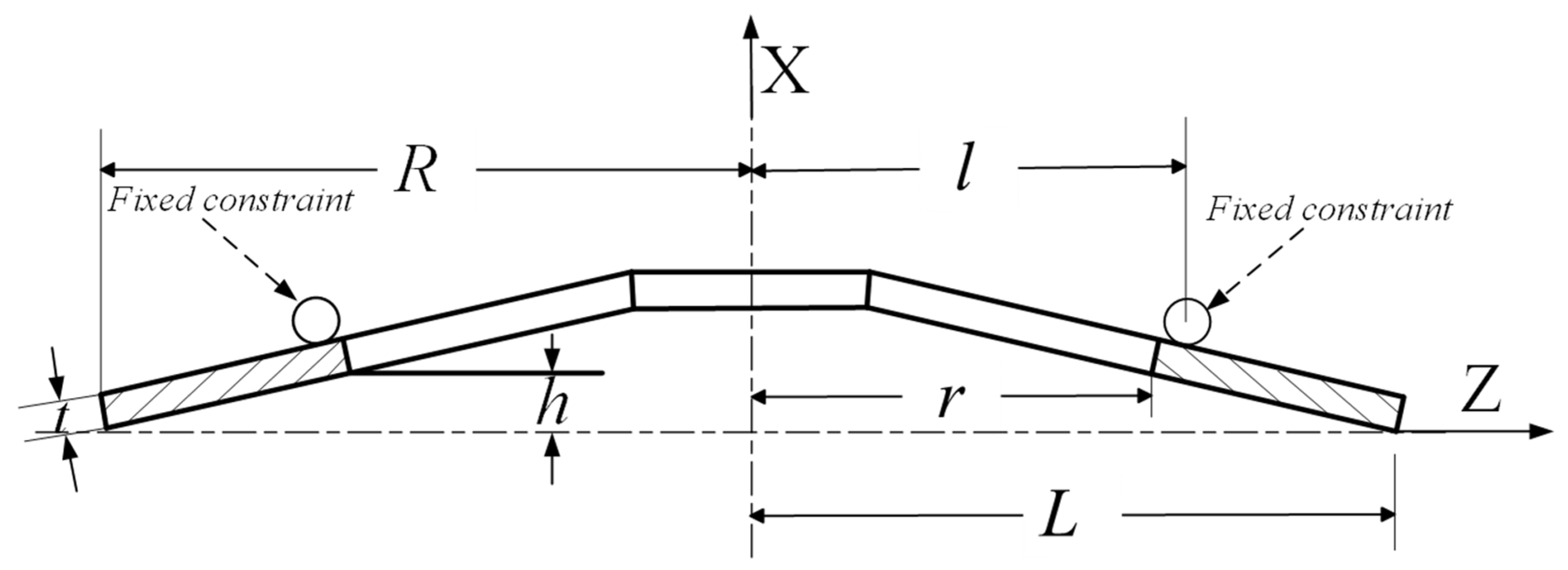
The diaphragm spring material is 50CrV4; its elastic modulus is 2.07 × 10⁵ MPa, and Poisson’s ratio is 0.29. The main structural parameters are shown in Figure 1 and Table 1.

2.2. Model Simplification and Mesh Generation

The disc spring serves as a model for theoretical analysis, while the diaphragm spring is an industrial product; their key distinction lies in the presence of separation fingers. The A-L formula, which focuses on the disc spring, targets the primary structural component influencing the mechanical properties of the diaphragm spring. To validate the simulation method by comparing finite element results with theoretical data, the geometric model first constructs the disc spring part without incorporating separation fingers. The axisymmetric nature of the disc spring allows mesh generation to be simplified by modeling a 1/4 sector, significantly reducing computational effort while maintaining accuracy.
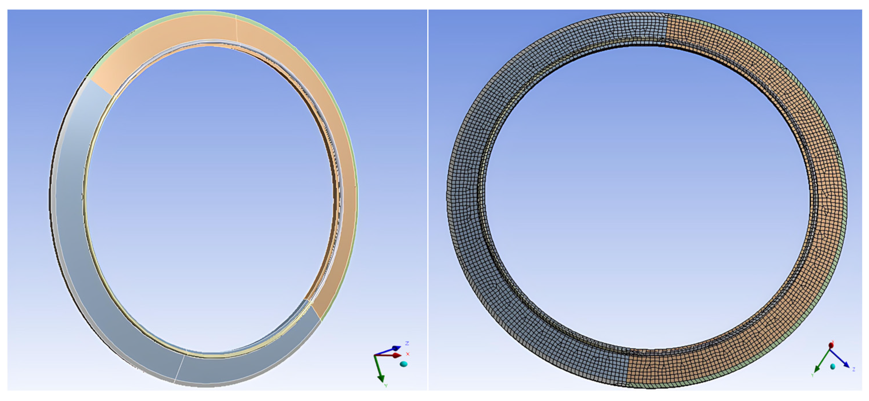
During the large end loading process of the disc spring, the support ring provides fixed support on its surface. To simulate the interaction between them, the geometric model of the support ring is also established. Meshing employs SOLID 226 elements for its suitability in capturing nonlinear deformation of spring steel components. A mesh convergence study was then conducted to determine the optimal element size: four configurations (1.5 mm, 1.9 mm, 2.5 mm, and 3.0 mm) were tested under identical boundary conditions. Key load indices (peak, valley, and inflection point) were compared as summarized in Table 2. The 1.9 mm mesh showed less than 2% deviation in key loads from the 1.5 mm mesh while reducing computational time and was thus selected to balance accuracy and efficiency. The meshing scheme is illustrated in Figure 2.

2.3. Setting of Boundary Conditions

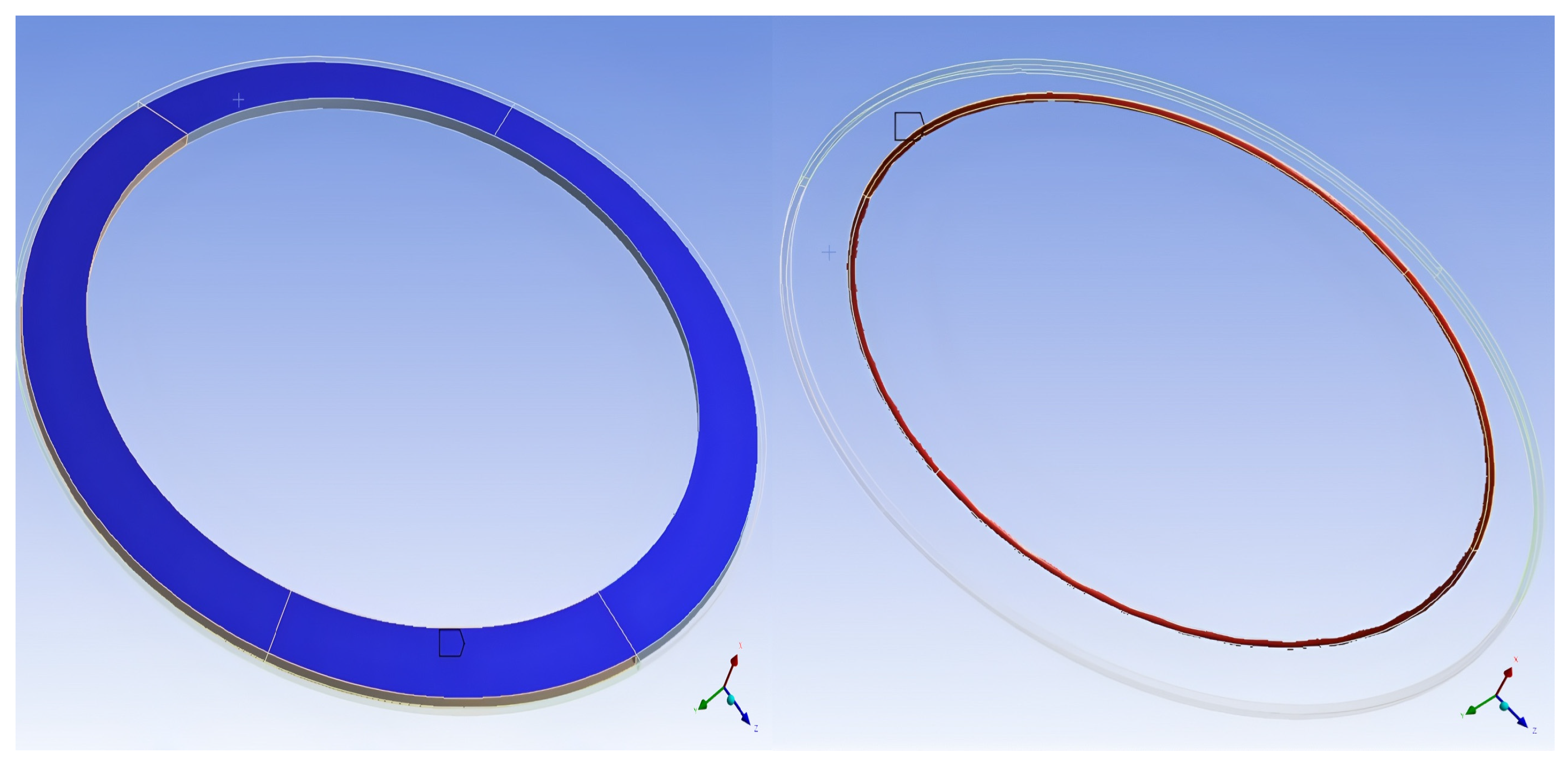
The contact between the disc spring and the support ring is set to face-to-face contact, with a friction coefficient of 0.1. The target surface is the upper surface of the contact area between the spring and the support ring, and the contact surface is the lower surface of the support ring. For contact stiffness, the typical range used in finite element analyses of diaphragm springs under steel-steel dry friction conditions is 0.1–0.2 [5]. This study sets contact stiffness to 0.1 to simplify calculations, as shown in Figure 3.
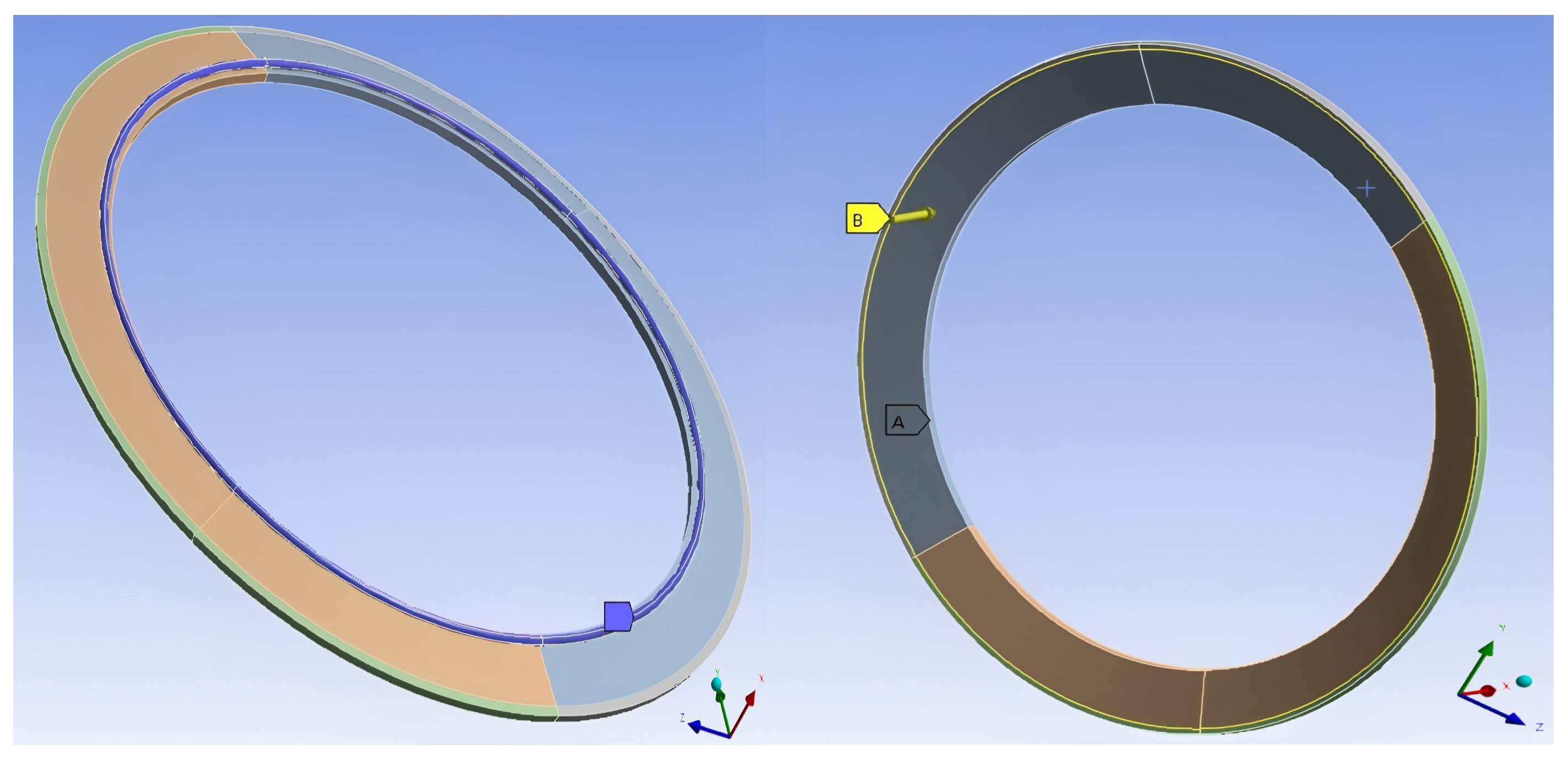
A fixed constraint is applied to the support ring, and a forced displacement of 6 mm in the X direction is applied to the annular area at the contact position between the disc spring and the pressure plate. This displacement matches the typical working stroke of commercial vehicle clutch diaphragm springs in practical operation and covers the critical stage of nonlinear deformation [16], with the Y and Z directions remaining free, as shown in Figure 4.
The load–displacement characteristic curve of the large end of the disc spring is a nonlinear problem caused by large deformation. Therefore, multiple load sub-steps need to be set in the solution process, and the large deformation solution switch needs to be opened.

2.4. Comparison of FEA and A-L Formula Theoretical Calculation Results

According to the A-L formula, the load–displacement relationship when the large end is loaded is [27]:
F 1 = π E t λ 1 l n ( R / r ) 6 ( 1 μ 2 ) ( L l ) 2 [ ( h k 1 λ 1 ) ( h 0.5 k 1 λ 1 ) + t 2 ]
In Equation (1): F 1 is the loading point load of the large end of the diaphragm spring, R is the outer radius of the diaphragm spring, r is the inner radius of the spring part, h is the inner cone height of the spring part in the free state, t is the thickness of the diaphragm spring plate, L is the radius of the contact line between the diaphragm spring and the pressure plate, l is the radius of the contact line between the diaphragm spring and the support ring, λ 1 is the displacement of the loading point of the large end of the diaphragm spring, E is the elastic modulus, μ is the Poisson’s ratio.
Different displacements are brought into the A-L formula to obtain the corresponding load. The calculation results are compared with the load–displacement results of the large end of the spring obtained by the finite element analysis, as shown in Figure 5. Quantifiable differences exist between the two: the general difference is around 12%, with a maximum difference of approximately 22%. This discrepancy is primarily attributed to the fact that the finite element model incorporates contact and friction effects between the support ring and the disc spring. Despite the numerical differences, the load–displacement curves of the two methods show a consistent overall trend, and the rationality of the difference source fully verifies the correctness of the finite element model.

3. Effect of Separation Finger Root Characteristics on Disc Spring

The existence of the separation finger part will affect the mechanical properties of the diaphragm spring. Therefore, it is also necessary to establish a diaphragm spring simulation model with a separation finger structure based on the disc spring. The main geometric differences of the diaphragm spring separation finger part are the size and shape of the separation finger hole, the length, and the number of the separation finger. This study analyzes and studies these influencing factors, respectively.

3.1. Different Square Hole Sizes with the Same Number of Separation Fingers

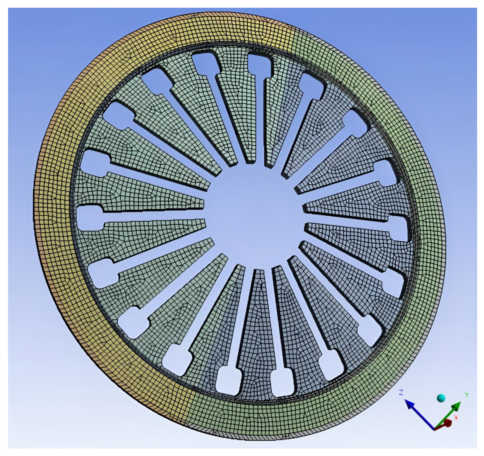
To study the influence of the square hole size of the separation finger on the load–displacement characteristic curve, a diaphragm spring with 18 separation fingers and square holes is established. The mesh model is shown in Figure 6. The symmetrical arrangement of square holes ensures that stress redistribution caused by size changes acts uniformly across the entire spring. The size of the aperture is divided into three groups: 8 mm, 10 mm, and 12 mm.
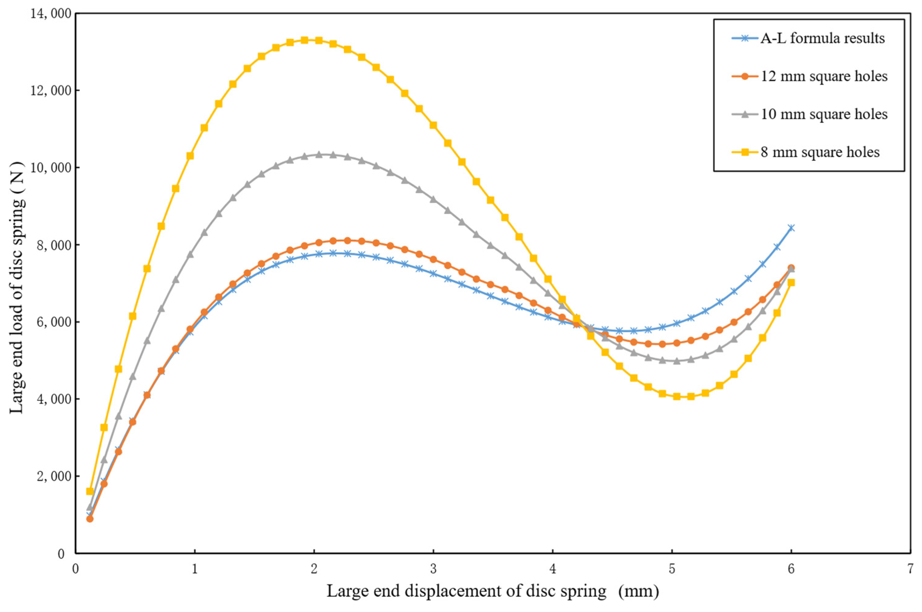
The load–displacement characteristic curves of the large end obtained by finite element analysis of the disc spring without separation fingers and the diaphragm spring with different square hole sizes are compared, as shown in Figure 7. As indicated in Table 3, the influence of different square hole sizes on the load–displacement curve of the separation finger root presents distinct patterns within the studied parameter range: when the square hole size increases from 8 mm to 12 mm, the load at 6 mm displacement increases from 7017.5 N to 7403.5 N, accompanied by a reduction in the difference from the A-L formula results (from 16.8% to 12.3%). This trend reveals that larger square holes lead to increased load under the same displacement, while simultaneously reducing the fluctuation of the load–displacement curve and narrowing the gap with theoretical predictions. A plausible explanation for the load increase lies in the structural effect of enlarged square holes: they may alleviate local stress concentration at the separation finger root, thereby expanding the effective load-bearing area of the material. Notably, the consistent decrease in deviation from the A-L formula (16.8% to 12.3%) confirms that increasing the square hole size drives the characteristic curve gradually closer to the theoretical model, despite the upward trend in absolute load values.

3.2. Different Circular Hole Sizes with the Same Number of Separation Fingers

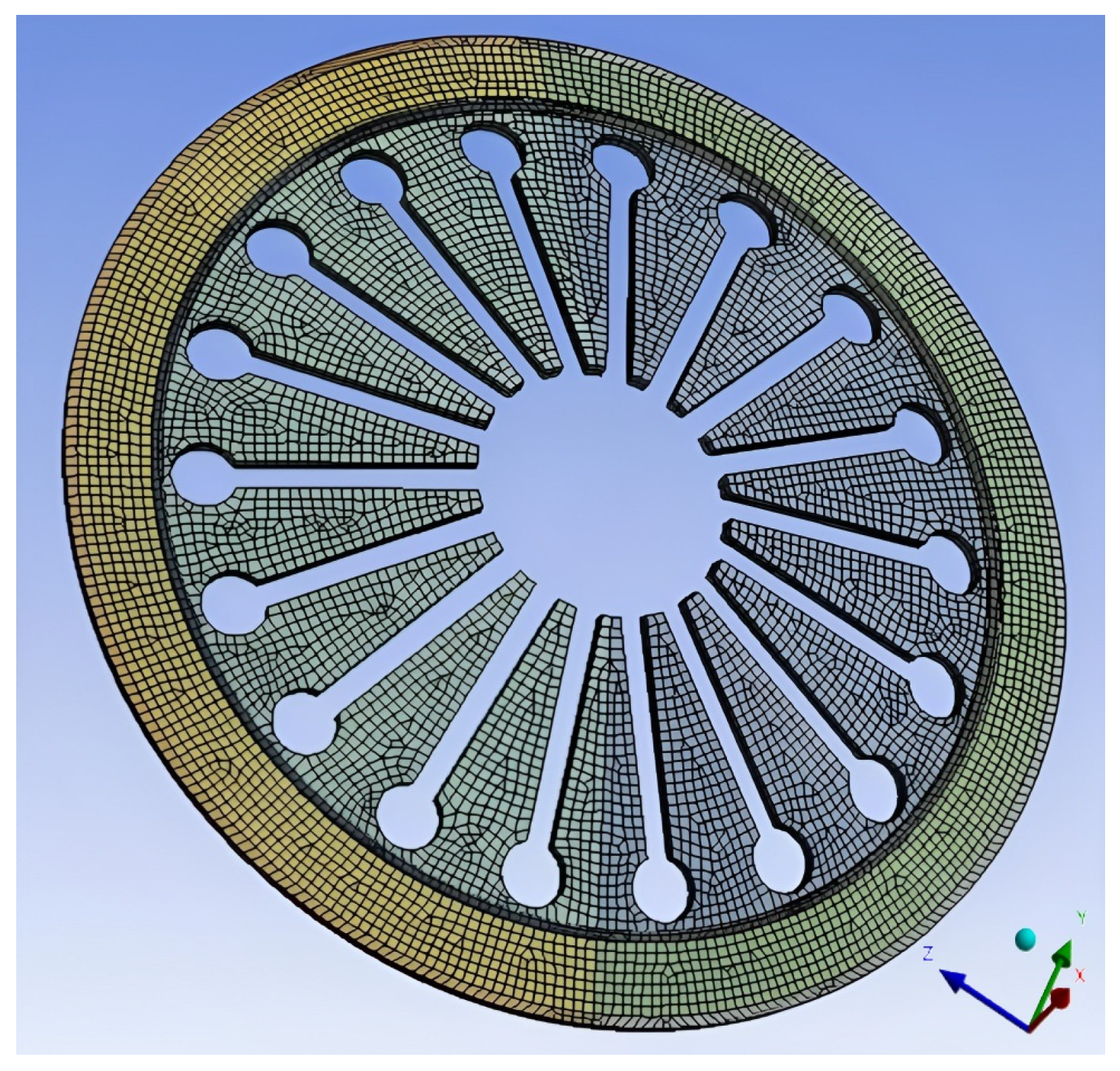
The mesh model of the diaphragm spring with 18 separation fingers and the root of each finger is a circular hole as shown in Figure 8. Similar to square holes, the symmetrical distribution of circular holes guarantees consistent load transmission across the diaphragm spring. The aperture sizes of the three groups were 8 mm, 10 mm, and 12 mm, respectively.
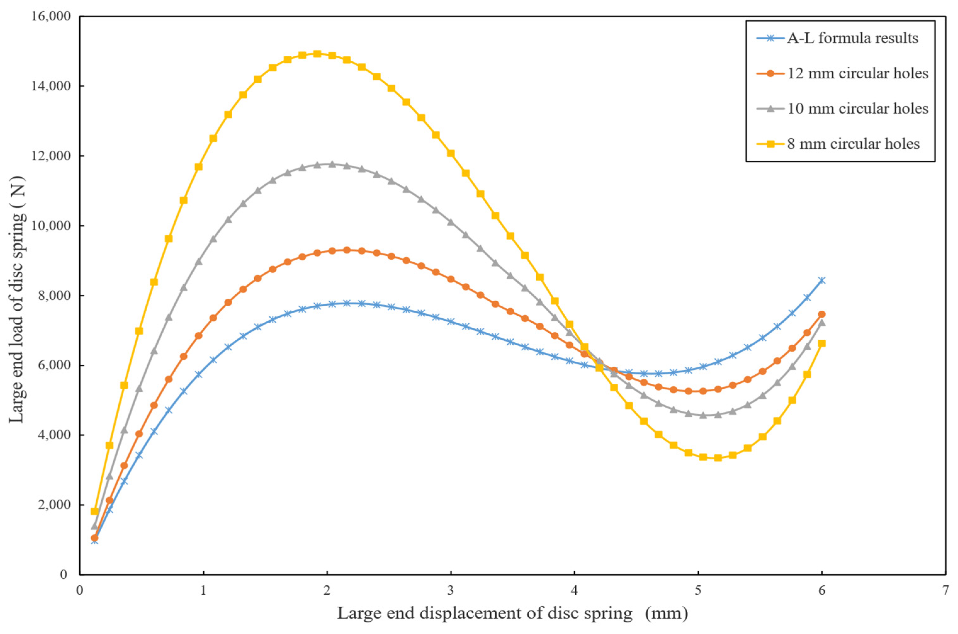
The load–displacement characteristic curves of the large end obtained by finite element analysis of the disc spring without a separation finger and the diaphragm spring with different circular apertures are compared, as shown in Figure 9. As presented in Table 4, which illustrates the load characteristics of different circular hole sizes with 18 separation fingers, when the circular hole size increases from 8 mm to 12 mm, the load at 6 mm displacement rises from 6627.0 N to 7462.5 N. Meanwhile, the difference from the A-L formula decreases from 24.5% to 11.6%. This shows that the influence of different circular hole sizes on the load–displacement characteristic curve is distinct; similar to square holes, increasing the circular hole size also makes the load–displacement characteristic curve of the diaphragm spring gradually approach the theoretical model of the A-L formula. Moreover, the load at the same displacement increases with the enlargement of the circular hole, implying that larger circular holes enhance the load-bearing capacity of the diaphragm spring under this condition. However, there is still a gap between the load–displacement curve of the large end of the 12 mm circular hole diaphragm spring and the results of the A-L formula, suggesting that the load–displacement curve of the diaphragm spring can be further changed by increasing the size of the circular hole.

3.3. Different Shapes with the Same Aperture

To study the influence of the shape of the hole on the load–displacement characteristic curve of the large end of the diaphragm spring, the finite element analysis results of 12 mm circular and square hole, 10 mm circular and square hole, and 8 mm circular and square hole are compared, respectively, as shown in Figure 10.
As shown in Table 5, for aperture sizes of 8 mm, 10 mm, and 12 mm, the maximum load of square holes is consistently lower than that of circular holes: at 8 mm, square holes have a maximum load of 13,302 N (10.9% less than circular holes); at 10 mm, it is 10,337 N (12.1% less); and at 12 mm, 8097.2 N (13.0% less). Careful observation of Figure 10 reveals that before a displacement of 4.32 mm, the load of square holes is smaller than that of circular holes, while after 4.32 mm, the load of circular holes becomes smaller than that of square holes. Additionally, from the diagram, the fluctuation of square holes with the same size is generally smaller than that of circular holes. The phenomenon that the load of square holes is smaller than that of circular holes under the same displacement before 4.32 mm (and vice versa after) indicates that the stiffness variation patterns of square hole and circular hole diaphragm springs differ with displacement. This is related to the fact that the area of a square hole with the same size is larger than that of a circular hole, which affects the force-bearing and deformation characteristics of the diaphragm spring at different displacement stages.

3.4. Different Lengths with the Same Number of Separation Fingers

To study the influence of the length of the separation finger on the load–displacement characteristic curve, the following 18 diaphragm springs with square holes but short separation fingers are established. The mesh model is shown in Figure 11. The size of the aperture is still divided into three groups: 8 mm, 10 mm, and 12 mm.
The load–displacement curve of the diaphragm spring with the same square hole size and different separation finger lengths is shown in Figure 12. It can be observed that, regardless of the square hole size, the load–displacement curves of the long and short separation fingers have only slight differences, which are very small and almost coincide. This visual result indicates that the fingertip part of the separation finger has little effect on the geometry of the load–displacement characteristic curve of the large end of the diaphragm spring.
As presented in Table 6, for an aperture size of 8 mm, the maximum load for both longer and shorter separation fingers is approximately 13,302 N and 13,301 N, respectively, with a difference of 0.0% from the 8 mm square hole longer separation finger. When the aperture size is 10 mm, the maximum load for longer separation fingers is 10,337 N and for shorter ones is 10,340 N, both showing a 22.3% difference from the 8 mm square hole longer separation finger. For a 12 mm aperture size, the maximum load for longer separation fingers is 8108.8 N and for shorter ones is 8110.3 N, with a 39.0% difference from the 8 mm square hole longer separation finger. These data further confirm that although there are minor variations in maximum load with different separation finger lengths under the same square hole size, the overall impact on the load–displacement relationship is negligible. Thus, in the design stage, the working curve of the diaphragm spring cannot be effectively designed by changing the length of the separation finger.

3.5. Different Number of Separation Fingers

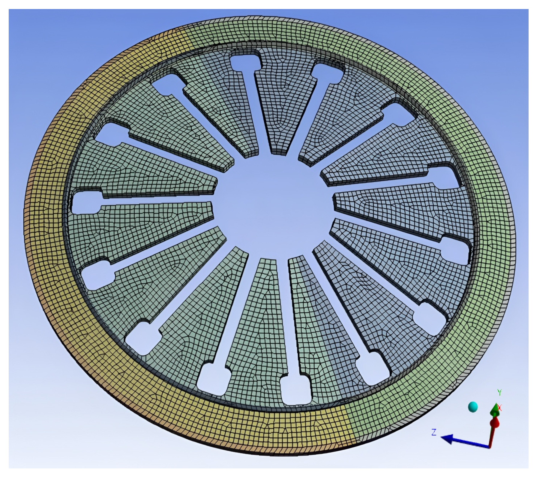
To study the influence of the number of separation fingers on the load–displacement characteristics of the large end of the diaphragm spring, the following 14 diaphragm springs with the apertures of 8 mm, 10 mm, and 12 mm square holes of the separation fingers are established, as shown in Figure 13.
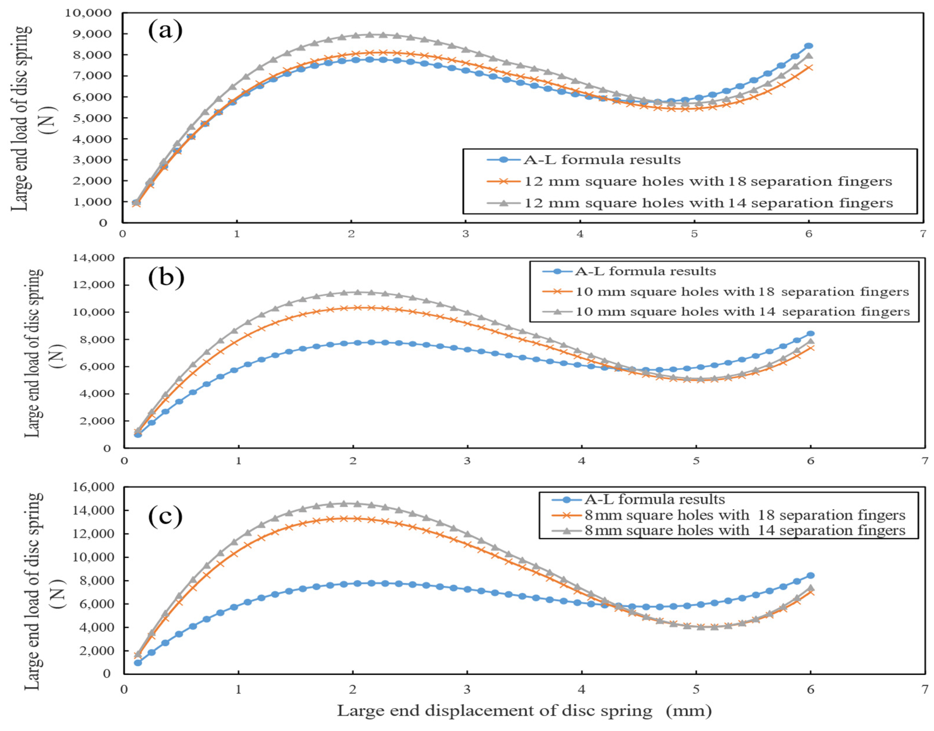
From Figure 14, the load–displacement curve fluctuation of the 18 separation fingers with the same square hole size is smaller than that of the large end of the 14 separation fingers diaphragm spring, and the load of the 18 separation fingers with the same displacement is smaller than that of the 14 separation fingers. Increasing the number of separation fingers enhances rotational symmetry, thereby reducing load fluctuation by distributing force more evenly. As presented in Table 7, for an aperture size of 8 mm, the maximum load with 14 separation fingers is 14,598 N, showing a 9.7% difference from the same-size square hole with 18 separation fingers (where the maximum load is 13,302 N). At 10 mm aperture size, the maximum load for 14 separation fingers is 11,476 N, with an 11.0% difference from the 18 separation fingers (maximum load 10,337 N). For a 12 mm aperture size, the maximum load for 14 separation fingers is 8964.1 N, having a 10.7% difference from the 18 separation fingers (maximum load 8097.2 N). This is because the number of windows of the 18 separation fingers is more than that of the 14 separation fingers, and the area of the root of the separation finger is dug more, so the corresponding stiffness is smaller. In the design stage, the working curve of the diaphragm spring can be designed by changing the number of separation fingers.

4. Discussion

In this study, the mechanical properties of the diaphragm spring obtained by finite element simulation can be analyzed in depth from the effectiveness of the simulation method and the influence mechanism of structural parameters.
From the simulation method, the comparison between the finite element model and the A-L formula shows that the two trends are consistent and the difference is small (Figure 5), which verifies the applicability of the model to the large deformation nonlinear problem of the diaphragm spring. Compared with the traditional A-L formula, the advantage of finite element simulation is that it can accurately capture the subtle influence of the separation finger structure on the load–displacement characteristics, which is difficult to achieve by the A-L formula, because it is only applicable to the simplified disc spring model and cannot include the geometric effects of complex structures such as the separation finger. For example, when the size of the square hole at the root of the separation finger increases from 8 mm to 12 mm, the simulation results (Table 3) clearly show that the load at 6 mm displacement increases from 7017.5 N to 7403.5 N, and the difference from the A-L formula results reduces from 16.8% to 12.3%, confirming that the load–displacement curve gradually approaches the theoretical model. This continuous change in stiffness, quantified by specific load values and deviation percentages, is difficult to capture through the A-L formula, while finite element simulation achieves precise tracking through mesh discretization.
From the simulation results of the influence of structural parameters, the size and shape of the separation finger root hole are the core factors regulating the characteristic curve (Figure 7, Figure 9 and Figure 10). For circular holes (Table 4), when the size increases from 8 mm to 12 mm, the load at 6 mm displacement rises from 6627.0 N to 7462.5 N, and the difference from the A-L formula decreases from 24.5% to 11.6%, showing a similar trend to square holes in approaching the theoretical model but with a more significant load increase (12.6% vs. 5.5% for square holes). For hole shape (Table 5), under the same aperture, the maximum load of square holes is consistently lower than that of circular holes by 10.9% (8 mm), 12.1% (10 mm), and 13.0% (12 mm). Notably, careful observation of Figure 10 reveals a displacement-dependent relationship: before 4.32 mm displacement, the square hole load is smaller than the circular hole, while after this point, the trend reverses, which is closely related to the larger material removal area of square holes (15–20% larger than circular holes of the same size) and the stress redistribution in different deformation stages. In addition, the increase in the number of separation fingers (e.g., from 14 to 18) reduces stiffness (Figure 14). Table 7 shows that for 12 mm square holes, the maximum load decreases by 10.7% (from 8964.1 N to 8097.2 N) when the number increases, which is because more separation fingers disperse the load and reduce stress concentration per unit area, providing a quantitative basis for optimizing clutch operating force.
It is worth noting that the simulation results (Table 6) confirm that “the length of the separation finger has no significant effect on the characteristic curve” (Figure 12): under the same square hole size, the maximum load difference between long and short separation fingers is less than 0.1% (e.g., 13,302 N vs. 13,301 N for 8 mm aperture). Simulation shows that stress is mainly concentrated in the root area (over 90% of total stress), with negligible stress changes in the fingertip, so the impact on overall stiffness is weak. This provides flexibility for diaphragm spring adaptation—length can be adjusted according to assembly space without rechecking load characteristics. The symmetry of separation finger distribution is a key reason for balanced load–displacement curves, as asymmetric designs would introduce uneven stress concentrations.

5. Conclusions

This study systematically analyzed the mechanical properties of diaphragm springs for commercial vehicle clutches using the finite element method, focusing on the influence of separation finger structural parameters on large-end load–displacement characteristics. The finite element model was validated by comparison with the A-L formula, confirming its reliability in simulating large-deformation nonlinear behavior. Key findings include:
(1)
The size, shape of the separation finger root hole, and the number of separation fingers are critical factors regulating the load–displacement curve—larger holes, square holes (vs. circular holes), and more separation fingers reduce stiffness effectively.
(2)
Separation finger length has negligible impact on the characteristic curve, allowing flexible adjustment based on assembly space without affecting core load properties.
These results provide direct guidance for optimizing diaphragm spring design in commercial vehicle clutches. Notably, these findings underscore the critical role of structural symmetry, particularly axisymmetry and symmetrical distribution of separation fingers, in regulating load–displacement stability, offering a symmetry-based design framework for industrial applications.
However, there are still some limitations in this study: the model does not consider the influence of material nonlinearity (such as plastic deformation) and temperature on mechanical properties, while the temperature rise may lead to the degradation of material properties when the clutch of a heavy commercial vehicle works under long term high load; in addition, the influence of stress concentration at the root of the separation finger on the fatigue life is not involved, which is also a key issue to be concerned about in practical applications.
Future research can be expanded from three aspects: first, the introduction of a material elastic-plastic model and thermal-structural coupling analysis, closer to the actual working conditions; secondly, the simulation results are verified by experimental tests, and the fatigue life prediction is carried out. Thirdly, based on the multi-objective optimization algorithm, the global optimal design of the diaphragm spring is realized by considering the stiffness, stress distribution, and weight.
Author Contributions

M.C. and Z.S. contributed to the conceptualization, methodology, software, visualization, and design of the study, as well as to the drafting and revision of the manuscript. P.M. contributed to the conceptualization and design of the study, as well as to the drafting and revision of the manuscript. J.Z. assisted in the completion of the experiments and was involved in the drafting and revision of the manuscript. All authors have read and agreed to the published version of the manuscript.

Funding

This work was supported by the Wuhan City Polytechnic High-level talents Foundation (Grant No. 2024WHCPRB02) and the Natural Science Project of Hubei Automobile After-sales Service Industry Association (Grant No. 2025QCSH003) and the Hubei Provincial Science and Technology Innovation Base (Platform) Program Project (Grant No. 2024CSA082).

Data Availability Statement

The original contributions presented in this study are included in the article. Further inquiries can be directed at the corresponding author.

Conflicts of Interest

The authors declare no conflicts of interest.

References

  1. Lin, X.; Xi, J.; Hao, S. The calculation model of the friction torque on a dry clutch. Proc. Inst. Mech. Eng. Part D J. Automob. Eng. 2017, 231, 1796–1805. [Google Scholar] [CrossRef]
  2. Yan, Z.; Wu, B.; Gao, X.; Bai, X. Engagement/Disengagement Characteristics of Pull-Type Diaphragm Spring Clutch for Heavy-Duty Commercial Vehicles. Chin. J. Mech. Eng. 2024, 37, 124. [Google Scholar] [CrossRef]
  3. Yuan, D.; Li, F.; Zheng, F. Calculation of characteristic curves of diaphragm springs based on nonlinear finite element method. J. Zhejiang Univ. Technol. 2009, 37, 350–354. [Google Scholar]
  4. Doman, Y.; Fujii, T.; Okubo, K.; He, H. Influence of residual stress on the load–deflection curve of diaphragm springs for automobile clutches. JSAE Rev. 2003, 24, 197–203. [Google Scholar] [CrossRef]
  5. Lin, E.; Gui, L.; Fan, Z. Finite element analysis of the mechanical properties of diaphragm springs. Autom. Eng. 2010, 32, 892–896. [Google Scholar]
  6. Yan, Z.; Yan, F.; Liang, J.; Duan, Y. Detailed modeling and experimental assessments of automotive dry clutch engagement. IEEE Access 2019, 7, 59100–59113. [Google Scholar] [CrossRef]
  7. Shi, J.; Wu, G. Sensitivity analysis of load characteristics and comparison of research methods for clutch diaphragm springs. Mech. Transm. 2013, 37, 113–118. [Google Scholar]
  8. Wang, B. Simulation analysis of characteristic curves of diaphragm springs based on finite element method. Tract. Farm Transp. 2007, 34, 90–92. [Google Scholar]
  9. Zhang, S.; Zhao, S.; Zhu, D.; Liu, H.; Liu, G. Experimental and simulation analysis of mechanical properties of disc springs. J. Hunan Univ. (Nat. Sci. Ed.) 2018, 45, 64–73. [Google Scholar]
  10. Hou, Q.; Chen, H.; Wang, S.; Zhang, Q. Mechanical characteristic analysis of force-sensing disc springs for self-adjusting clutches. J. Hubei Univ. Automot. Technol. 2015, 29, 6–8. [Google Scholar]
  11. Shin, Y.H.; Lee, J.H. Estimation of the complex dynamic stiffness of inflated rubber diaphragms in pneumatic springs using finite element method. Sensors 2020, 20, 6728. [Google Scholar] [CrossRef] [PubMed]
  12. Bai, Y.; Shi, P. Thermal stress and strain analysis of dry diaphragm spring clutches. Mach. Des. Res. 2014, 30, 83–88. [Google Scholar]
  13. Della Gatta, A.; Iannelli, L.; Pisaturo, M.; Senatore, A.; Vasca, F. A survey on modeling and engagement control for automotive dry clutch. Mechatronics 2018, 55, 63–75. [Google Scholar] [CrossRef]
  14. Shi, X.; Huang, X.; Zhang, Z.; Yao, L. Thermo-structural coupling analysis of clutch diaphragm springs. Autom. Eng. 2013, 35, 435–438. [Google Scholar]
  15. Wang, Y.; Li, Y.; Li, N.; Sun, H.; Wu, C.; Zhang, T. Time-varying friction thermal characteristics research on a dry clutch. Proc. Inst. Mech. Eng. Part D J. Automob. Eng. 2014, 228, 510–517. [Google Scholar] [CrossRef]
  16. Zhao, H.; Zhang, G.; Wang, B. Numerical simulation of the influence of constraints on the characteristics of diaphragm springs. Manuf. Autom. 2015, 37, 75–77. [Google Scholar]
  17. Shangguan, W.B.; Liu, X.L.; Rakheja, S.; Hou, Q. Effective utilizing axial nonlinear characteristics of diaphragm spring and waveform plate to enhance breakaway performances of a clutch. Mech. Syst. Signal Process. 2019, 125, 123–141. [Google Scholar] [CrossRef]
  18. Liu, J.; Tang, G. Analysis of performance and structural changes of leaf springs during storage. Modern Manuf. Eng. 2013, 5, 122–125. [Google Scholar]
  19. Li, J.Y.; Chen, Z.H. Optimization analysis and life evaluation of self-adjusting diaphragm spring clutches. Bull. Sci. Technol. 2022, 38, 44–48. [Google Scholar]
  20. Zhou, J.; Liu, Y.; Yin, J.; Gao, J.; Hou, N. Improved Particle Swarm Algorithm Based Multi-Objective Optimization of Diaphragm Spring of the Clutch. Mechanics 2022, 28, 410–416. [Google Scholar] [CrossRef]
  21. Karaduman, A.; Yıldız, B.S.; Yıldız, A.R. Experimental and numerical fatigue-based design optimisation of clutch diaphragm spring in the automotive industry. Int. J. Veh. Des. 2019, 80, 330–345. [Google Scholar] [CrossRef]
  22. Kaya, N. Optimal design of an automotive diaphragm spring with high fatigue resistance. Int. J. Veh. Des. 2006, 40, 126–143. [Google Scholar] [CrossRef]
  23. Hajavifard, R.; Maqbool, F.; Schmiedt-Kalenborn, A.; Buhl, J.; Bambach, M.; Walther, F. Integrated forming and surface engineering of disc springs by inducing residual stresses by incremental sheet forming. Materials 2019, 12, 1646. [Google Scholar] [CrossRef]
  24. Qing, P.; Ren, M.; Qiu, Q. Research on the application of DFMEA for diaphragm spring clutch cover assemblies. Mech. Transm. 2014, 38, 166–170. [Google Scholar]
  25. Xu, P.; Zhao, X.; Zhang, K.; Wang, L.; Liu, X. Design of parametric system for diaphragm spring clutch based on Pro/Toolkit. J. Shandong Agric. Univ. (Nat. Sci. Ed.) 2014, 45, 541–544. [Google Scholar]
  26. Li, L.; Wang, X.; Hu, X.; Chen, Z.; Song, J.; Muhammad, F. A modified predictive functional control with sliding mode observer for automated dry clutch control of vehicle. J. Dyn. Syst. Meas. Control 2016, 138, 061005. [Google Scholar] [CrossRef]
  27. Lin, S.Y.; Fan, H.R.; Liu, X.Z. Design and Manufacturing Diaphragm Spring and Disc Spring Clutches; Southeast University Press: Nanjing, China, 1995. [Google Scholar]
Figure 1. Main structure diagram of diaphragm spring.
Symmetry 17 01378 g001
Figure 2. Disc spring geometry and mesh model with SOLID 226 elements and 1.9 mm size.
Symmetry 17 01378 g002
Figure 3. Contact surface setting between disc spring and support ring.
Symmetry 17 01378 g003
Figure 4. Load setting with 6 mm axial displacement on annular contact area.
Symmetry 17 01378 g004
Figure 5. Comparison of FEA and A-L formula results of disc spring.
Symmetry 17 01378 g005
Figure 6. FEA model of diaphragm spring with 18 separation fingers and square holes.
Symmetry 17 01378 g006
Figure 7. Comparison of A-L formula with FEA results of different square holes.
Symmetry 17 01378 g007
Figure 8. FEA model of diaphragm spring with 18 separation fingers and circular holes.
Symmetry 17 01378 g008
Figure 9. Comparison of A-L formula with FEA results of different circular holes.
Symmetry 17 01378 g009
Figure 10. Comparison of FEA results of circular hole and square hole. (a) 12 mm circular hole, square hole, and A-L formula load–displacement curves; (b) 10 mm circular hole, square hole, and A-L formula load–displacement curves; (c) 8 mm circular hole, square hole, and A-L formula load–displacement curves.
Symmetry 17 01378 g010
Figure 11. FEA model of diaphragm spring with shorter square hole separation fingers.
Symmetry 17 01378 g011
Figure 12. Comparison of different separation finger lengths with the same square hole size. (a) The length of different separation fingers of 12 mm square holes and A-L formula load–displacement curves; (b) The length of different separation fingers of 10 mm square holes and A-L formula load–displacement curves; (c) The length of different separation fingers of 8 mm square holes and A-L formula load–displacement curves.
Symmetry 17 01378 g012
Figure 13. FEA model of diaphragm spring with 14 separation fingers and square holes.
Symmetry 17 01378 g013
Figure 14. Different number of separation fingers with the same aperture square holes. (a) The curves of 14 and 18 separation fingers with 12 mm square holes; (b) The curves of 14 and 18 separation fingers with 10 mm square holes; (c) The curves of 14 and 18 separation fingers with 8 mm square holes.
Symmetry 17 01378 g014
Table 1. Main structural parameters of diaphragm spring.
ParametersSymbolsValuesUnit
Diaphragm spring thickness t 2.43 mm
Diaphragm spring outer radius R 92.8 mm
Inner radius of the spring part r 76 mm
Diaphragm spring and pressure plate contact line radius L 91.35 mm
Diaphragm spring and support ring contact line radius l 78.3 mm
The height of the inner core of the spring part in the free state h 4.38 mm
Table 2. Comparison of key load deviations for different mesh sizes.
Mesh Size (mm)Peak Load Deviation (%)Valley Load Deviation (%)Inflection Point Load Deviation (%)
1.5000
1.91.81.51.7
2.54.23.94.0
3.07.57.17.3
The deviation values are based on the calculation results of the 1.5 mm mesh.
Table 3. Load characteristics of different square hole sizes (18 separation fingers).
Square Hole Size (mm)Load at 6 mm Displacement (N)Difference from A-L Formula (%)Difference from 8 mm Square Hole (%)
87017.516.80
107376.512.65.1
127403.512.35.5
Table 4. Load characteristics of different circular hole sizes (18 separation fingers).
Circular Hole Size (mm)Load at 6 mm Displacement (N)Difference from A-L Formula (%)Difference from 8 mm Square Hole (%)
86627.024.50
107230.314.39.1
127462.511.612.6
Table 5. Load characteristics of different hole shapes (18 separation fingers).
Aperture Size (mm)Hole ShapeMaximum Load (N)Maximum Difference from Same-Size Circular Hole (%)
8Circular14,9280
8Square13,30210.9
10Circular11,7650
10Square10,33712.1
12Circular9302.50
12Square8097.213.0
Table 6. Load characteristics of different separation finger lengths (same square hole size).
Aperture Size (mm)Separation Finger LengthMaximum Load (N)Difference from 8 mm Square Hole Longer (%)
8Longer13,3020.0
8Shorter13,3010.0
10Longer10,33722.3
10Shorter10,34022.3
12Longer8108.839.0
12Shorter8110.339.0
Table 7. Load characteristics of different numbers of separation fingers (same square hole size).
Aperture Size (mm)Number of Separation FingersMaximum Load (N)Maximum Difference from Same-Size Square Hole (%)
81414,5989.7
81813,3020
101411,47611.0
101810,3370
12148964.110.7
12188097.20
Disclaimer/Publisher’s Note: The statements, opinions and data contained in all publications are solely those of the individual author(s) and contributor(s) and not of MDPI and/or the editor(s). MDPI and/or the editor(s) disclaim responsibility for any injury to people or property resulting from any ideas, methods, instructions or products referred to in the content.