Abstract
This study introduces a memristive Hopfield neural network (M-HNN) model to investigate electromagnetic radiation impacts on neural dynamics in complex electromagnetic environments. The proposed framework integrates a magnetic flux-controlled memristor into a three-neuron Hopfield architecture, revealing significant alterations in network dynamics through comprehensive nonlinear analysis. Numerical investigations demonstrate that memristor-induced electromagnetic effects induce distinctive phenomena, including coexisting attractors, transient chaotic states, symmetric bifurcation diagrams and attractor structures, and constant chaos. The proposed system can generate more than 12 different attractors and extends the chaotic region. Compared with the chaotic range of the baseline Hopfield neural network (HNN), the expansion amplitude reaches 933%. Dynamic characteristics are systematically examined using phase trajectory analysis, bifurcation mapping, and Lyapunov exponent quantification. Experimental validation via a DSP-based hardware implementation confirms the model’s operational feasibility and consistency with numerical predictions, establishing a reliable platform for electromagnetic–neural interaction studies.
1. Introduction
In recent years, artificial neural networks have garnered extensive attention for their ability to simulate the complex dynamic behaviors of biological neural systems. As a representative recurrent neural network model, the HNN has become an essential tool in studying the nonlinear characteristics of neural activities due to its well-defined structure, the ease of its implementation in hardware, and its strong association with dynamic processes [1]. However, real biological neural networks are often significantly influenced by external environmental factors, such as electromagnetic radiation. Research indicates that electromagnetic radiation can interfere with neuronal electrical activities by altering the magnetic flux across the neuronal membrane [2,3], leading to intricate dynamic phenomena like chaos and multistability within neural networks [4]. To quantitatively analyze these effects, memristors have been incorporated into neural network research as an ideal component [5,6,7]. Their nonlinear conductance properties and magnetic flux modulation mechanisms offer a novel approach to elucidating neural dynamics [8].
With the deeper exploration of the complex dynamic behaviors of the biological nervous system, the modulatory effects of electromagnetic radiation on neural activities have gradually emerged as a critical research topic in both neuroscience and information engineering [9,10,11]. Memristors are particularly suitable for electromagnetic–neural simulation due to their analog resistive switching characteristics that mimic synaptic plasticity. More importantly, the flux-voltage hysteresis behavior of memristors has a direct correspondence with the response of the neuronal membrane to electromagnetic radiation, enabling real-time simulations of radiation effects at the microsecond level [12]. Early studies simulated the influence of electromagnetic induction on neuronal membrane potentials by incorporating ideal memristor models, such as hyperbolic tangent functions and quadratic nonlinear functions [13]. For instance, the hyperbolic tangent memristor describes the hysteresis effect of electromagnetic induction currents using a piecewise nonlinear function, while the quadratic nonlinear memristor characterizes the nonlinear relationship between radiation intensity and the oscillation amplitude of the membrane potential [14]. This modeling approach not only generates multi-scroll attractors and grid chaos but also enables continuous switching among periodic, quasi-periodic, and chaotic states by modulating the memristive coupling strength [4]. Furthermore, the non-volatility of memristors allows them to simulate the cumulative effects of electromagnetic radiation, offering a theoretical framework for investigating the long-term pathological mechanisms underlying neurodegenerative diseases [15].
Recently, the introduction of locally active memristors has substantially broadened the research scope in electromagnetic radiation simulations. These memristors not only possess non-volatile storage capabilities but also exhibit complex multistable behaviors through their negative resistance characteristics [16,17]. For instance, Yu et al. incorporated quadratic nonlinear memristors into neural networks, demonstrating that variations in electromagnetic radiation intensity can trigger transient coexisting attractors and multistage discharge modes, thus providing a theoretical foundation for high-density information encoding [18]. Simultaneously, Wan et al. developed a locally active memristor based on a cosine function, effectively simulating the multistability of self-synaptic connections in an electromagnetic environment. Through FPGA hardware experiments, they further validated its potential application in image encryption [19]. Building on this, Wan et al. [20] recently proposed a novel memristive self-synaptic coupled HNN model with local activity under electromagnetic radiation, which is characterized by a quadratic memristor. This model demonstrates non-volatile behavior and local activity, while exhibiting a wide range of dynamic properties, such as stable equilibria, periodic and chaotic attractors, bifurcations, and coexisting attractor phenomena. These dynamical features have been validated through PSIM simulations and implemented on a field-programmable gate array (FPGA). Moreover, Kong et al. integrated the fractional-order memristor model with hyperchaotic theory, proposing a multi-scroll attractor generation mechanism for the HNN under the influence of electromagnetic radiation. This advancement paves a new path for high-dimensional information encryption technology [21]. Lai and Yang [22] further explored hyperchaotic dynamics under electromagnetic radiation using a constructed local active discrete memristor, showing its induction of hyperchaotic attractors and three-point coexistence attractors in neurons, with implications for neurological disease mechanisms and randomness generation validated via digital circuits. Collectively, these studies suggest that memristors, by coupling the electromagnetic radiation effect with synaptic weight adjustments, can accurately replicate the chaotic dynamics and periodic alternations observed in human brain neural activities, thereby increasing innovative momentum in the fields of brain-like computing and biomedical engineering [23,24,25].
Although existing research has significantly deepened our understanding of the memristor-enhanced Hopfield neural network (M-HNN) under electromagnetic radiation, this study makes unique contributions in terms of model design, dynamic behavior analysis, and control mechanisms.
First, the sinusoidal memristor model adopted in this paper differs from the commonly used quadratic nonlinear memristors in Refs. [18,20] and the discrete memristor in Ref. [22]. This choice enables the system to exhibit unique attractor movement and scaling behaviors driven by internal parameters. Unlike the multistability phenomena reported in Refs. [16,19,20], this study reveals that parameter a induces a linear translation of the attractor along the magnetic flux φ axis, while parameter b governs its scaling or compression in the φ direction. Consequently, the geometric regulation of the chaotic attractor is achieved—a phenomenon that has not been thoroughly explored in previous studies.
Moreover, by altering the sign of the sine term, we observe symmetric bifurcation diagrams and attractor structures, offering a straightforward approach to generating symmetric solutions and further enriching the system’s dynamic diversity. Compared to the chaotic range expansion mechanisms described in Refs. [15,17,21], the proposed model exhibits an exceptionally wide chaotic region, with the chaotic interval expanding by up to 933% relative to traditional Hopfield neural networks.
Finally, while previous studies typically focus on hardware verification, this work successfully implements complex dynamic behaviors such as attractor movement on a digital DSP platform, thereby validating the model’s potential for future neuromorphic computing applications.
The rest of this paper is organized as follows. In Section 2, the sinusoidal memristor model is formulated and its hysteresis loops are simulated under variable frequencies/amplitudes, followed by integration into the Hopfield neural network to construct the M-HNN framework. In Section 3, bifurcation analysis, Lyapunov exponent spectra, and dynamic attractor maps are employed to investigate the multistability, transient chaos, and extreme multistability of the M-HNN under electromagnetic radiation modulation. In Section 4, the proposed memristive neural network is realized on a DSP-based digital experimental platform, with hardware validation of chaotic dynamics. Finally, the conclusions and future applications in neuromorphic computing are given in Section 5.
2. The Memristor Model and Its Application in M-HNN Design
2.1. Model of the Memristor
A memristor is an electronic component with memory characteristics, and its resistance value can be dynamically adjusted based on the history of the current flow. Due to this property, memristors are considered ideal candidate devices for simulating the effects of electromagnetic radiation. In neural networks, signal transmission and intensity may be influenced by the effects. Memristors mimic this effect through their inherent memory properties and the feedback mechanism associated with neuronal membrane potential. As a component capable of responding within microseconds while retaining its prior state, the memristor offers advantages such as low power consumption and high integration density. To simulate the impact of external electromagnetic radiation on HNNs, this paper proposes a sinusoidal memristor model as follows:
where i, v, and φ, respectively, denote the input current, output voltage, and internal magnetic flux, while a and b represent the internal parameters of the memristor.
In order to verify the hysteresis curve characteristics of the aforementioned memristor model, a sinusoidal voltage source Vm = Asin(2πft) was selected as the external excitation signal. The parameters were set as a = b = 1. Under a fixed amplitude A = 3 V, frequencies of f = 1 Hz, 5 Hz, and 100 Hz were chosen, respectively, and the resulting hysteresis curves are presented in Figure 1. Additionally, under a fixed frequency f = 3 Hz, amplitudes of A = 3 V, 5 V, and 10 V were also selected, respectively. From Figure 1a,b, it can be observed that altering either the frequency f or the amplitude A leads to changes in the hysteresis curve. Further analysis reveals that as the frequency f increases, the area of the hysteresis curve gradually decreases, whereas as the amplitude A increases, the area of the hysteresis curve gradually increases. The phase plane oscillation plot (POP) diagrams corresponding to different parameters a and b are illustrated in Figure 1c,d. It is evident from these diagrams that the equilibrium points E1 and E2 both exhibit negative slopes, indicating that the memristor can achieve asymptotic stability after power-off, demonstrating non-volatile characteristics. Moreover, when the parameters a and b vary, the corresponding equilibrium points shift, implying that when this memristor is utilized in a chaotic system, the attractor it generates will shift or deform in response to changes in a and b.
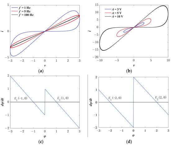
Figure 1.
Memristor characteristics under variable excitations and parameters: (a) Hysteresis curves at frequencies f = 1 Hz, 5 Hz, and 100 Hz with fixed amplitude A = 3 V; (b) Hysteresis curves at voltages A = 1 V, 5 V, and 10 V with fixed frequency f = 3 Hz; (c) Phase plane oscillation (POP) diagram for parameters a = b = 1; (d) POP diagram for parameters a = 2, b = 1.
2.2. The Construction of M-HNN
An HNN is a type of neural network with a recursive architecture [26]. An HNN consisting of n neurons can be formally defined as follows:
where Ci denotes the capacitance of the neuron, and the state variable xi represents the membrane potential of the i-th neuron. Ii characterizes the external environmental stimulus. Ri corresponds to the membrane resistance of the neuron cell membrane, the hyperbolic tangent function tanh(xj) serves as the nonlinear activation function of the neuron, and the synaptic coupling coefficient gij indicates the synaptic connection strength between the i-th and j-th neurons.
According to the definition in Equation (2), assuming Ci = 1 and Ri = 1, a three-neuron HNN structure containing self-synapses and bidirectional synaptic connections can be constructed as follows:
Furthermore, to enable the HNN to exhibit more diverse and complex dynamic behaviors, an external excitation signal I1 was designed, as defined in Equation (4). Here, the symbols F and H denote frequency and amplitude, respectively. k is a natural number, and t represents dimensionless time.
Taking H = 2 and F = 0.1, as well as H = 1 and F = 0.2, Figure 2 illustrates the variation in the time sequence of the external excitation I1. As t gradually increases, the external excitation I1 exhibits a periodic oscillation characteristic within the range of −H to H.
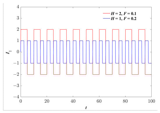
Figure 2.
The time sequence of the external excitation I1 when t ∈ [0, 100].
To investigate the impact of external electromagnetic radiation on the HNN, we simulated the effect of such radiation by introducing a memristor into the system and extending the HNN model described in Equation (3), as illustrated in Figure 3a. In this configuration, neurons are interconnected via bidirectional conductance (synaptic weights gij), forming a fully connected recurrent architecture. The memristor, denoted as W(φ), is specifically coupled to neuron 2, thereby modeling the localized influence of electromagnetic radiation on a targeted neuron. The topological layout of this enhanced model is presented in Figure 3b.
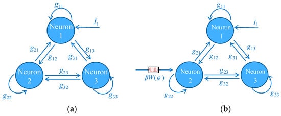
Figure 3.
Topological connections of different neural networks: (a) The original HNN structure, and (b) the proposed M-HNN structure.
The system state equation of the designed M-HNN model is presented in Equation (5). Table 1 summarizes the specific parameters of both the original HNN model and the newly developed M-HNN model. Most parameters in Table 1 are derived from the original HNN network. The values of g21, g13, and β have been adjusted to enhance the coupling strength, thereby exciting the chaotic attractor and introducing a saddle equilibrium state. Unless otherwise specified, these parameters will remain constant in the subsequent analysis.

Table 1.
The specific parameters of HNN and M-HNN.
3. Dynamical Analysis of M-HNN
3.1. Equilibrium Points
For chaotic systems, equilibrium point analysis not only reveals the complex dynamic characteristics of the system within specific parameter ranges but also provides a critical foundation for understanding the generation mechanism of chaotic attractors. Consequently, to investigate the dynamic behavior of the M-HNN and further elucidate the formation mechanism of chaotic attractors, this subsection performs an in-depth analysis of the equilibrium points. Specifically, the equilibrium points of the M-HNN can be determined by solving the following equation:
According to the parameter settings in Table 1, set the electromagnetic radiation intensity β = −0.18 and the parameters a = b = 1. Assuming the equilibrium point set of the system is E = (, , , ), the Jacobian matrix corresponding to this equilibrium point set can be expressed as follows:
where m = −0.8tanh2() − 0.18sin(π) − 0.38. By solving the Jacobian matrix of Equation (7), the eigenvalues corresponding to the equilibrium points can be determined, enabling further stability analyses, as shown in Table 2. The results indicate that the M-HNN model possesses four equilibrium points, all of which are unstable saddle-foci. This characteristic provides a necessary condition for the emergence of chaotic attractors.
Table 2.
Equilibrium points, eigenvalues and stability of the system.
3.2. Comparative Analysis of the Original HNN and M-HNN
An attractor is a complex geometric structure in a dynamical system, represented by the trajectory traced by the system in phase space. This paper conducts a comparative analysis of the original HNN and M-HNN (as shown in Figure 3). Based on the parameter settings provided in Table 1, the initial condition for the original HNN is set as IC0 = (0, 0, 0), while that for the M-HNN is set as IC1 = (0, 0, 0, 1). The bifurcation diagrams of both systems are presented in Figure 4a, b, respectively. As can be observed from the figures, there are substantial differences in the dynamic behaviors between the original HNN system (Figure 4a) and the enhanced M-HNN system (Figure 4b).
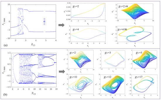
Figure 4.
Bifurcation diagrams and representative attractors versus synaptic weight g13 in the following: (a) original HNN system, showing period-doubling route to chaos within g13 ∈ [2.2, 2.8]; (b) M-HNN system, exhibiting expanded chaotic regimes (g13 ∈ [4.1, 8.7]∪[10.7, 12.5] and g13 ∈ [4.1, 8.7]∪[10.7, 12.5]) and typical attractors.
Specifically, the original HNN system demonstrates a relatively simple bifurcation pattern within the range of parameter g13 variation, including single-period attractors, period-doubling attractors, and chaotic attractors confined to a narrow region g13 ∈ [2.2, 2.8]. Its bifurcation diagram exhibits a relatively regular structure, with the chaotic region being more concentrated and limited to only four attractor types. In contrast, the bifurcation diagram of the M-HNN system exhibits significantly more complex and diverse dynamic behaviors. It expands the chaotic region to g13 ∈ [4.1, 8.7]∪[10.7, 12.5], resulting in a 933% increase in the chaotic parameter space. Within this extended range, the M-HNN system not only encompasses the four attractor types present in the original HNN but introduces additional novel types, resulting in over six distinct attractor types. More importantly, this broader and more dispersed chaotic region indicates a heightened sensitivity to initial conditions and stronger chaotic behavior. This increase in dynamic complexity is primarily attributed to memristor-related parameters enabling richer dynamics and more intricate attractor structures, giving the M-HNN greater advantages in chaotic signal generation and complex system modeling.
3.3. The Impact of Electromagnetic Radiation Intensity on Dynamic Behaviors
A further analysis of the influence of memristive intensity β on the HNN is conducted. Based on the system parameter settings outlined in Table 1, numerical simulations are performed with the initial condition IC1 = (0, 0, 0, 1). Figure 5a,b, respectively, depict the bifurcation diagram of the system state variable x3 and the corresponding Lyapunov exponent spectrum (LE1–LE3) as the memristive intensity β varies within the interval [−1.7, 0.3]. As β increases gradually from −1.7 to 0.3, the system demonstrates typical nonlinear bifurcation behavior. Specifically, when β ∈ [−1.7, −1.32], the system exhibits periodic dynamics. When β ≈ −1.17, it transitions into a chaotic state via period-doubling bifurcation before returning to a periodic state around β ≈ −0.87. Subsequently, as β increases to −0.37, the motion trajectory of the M-HNN evolves once again from a single-period state to a chaotic state, maintaining this behavior within the interval β ∈ [−0.37, 0.17].
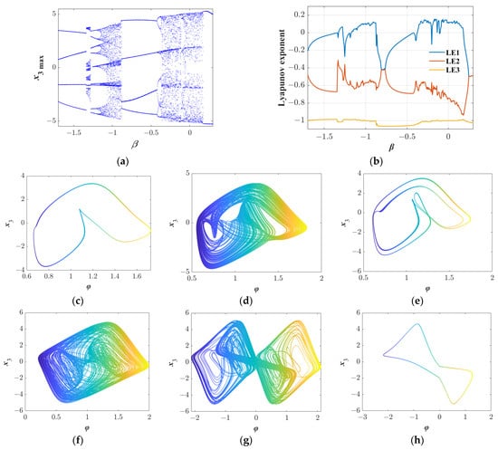
Figure 5.
Dynamics simulation diagrams of M-HNN varying with parameter β: (a) Bifurcation diagram, (b) Lyapunov exponent diagram, (c) Single-period attractor when β = −1.5, (d) Chaotic attractor when β = −1, (e) Multiple-period attractor when β = −1.2, (f) Chaotic attractor when β = −0.3, (g) Double-vortex chaotic attractor when β = 0, and (h) Single-period attractor when β = 0.4.
The Lyapunov exponent spectrum presented in Figure 5b provides compelling evidence for the chaotic nature of the system. Within the chaotic regime, the maximum Lyapunov exponent (LE1) remains consistently positive, which signifies a positive divergence rate and thereby confirms the system’s chaotic behavior. Simultaneously, LE2 and LE3 are both negative, indicating convergence in other directions. Furthermore, under varying β conditions, the attractors’ morphologies exhibit significant diversity, as illustrated in Figure 5c–h. A systematic classification of attractor types across β regimes is provided in Table 3. For instance, when β = −1.2, the system demonstrates a stable single-period attractor. When β = 0, it forms a complex double-vortex chaotic attractor, and the system transitions to a kinked attractor with β = 0.4. These distinct attractor morphologies suggest that the intensity β can effectively modulate the dynamic behavior of the system, enabling it to exhibit rich and diverse dynamical characteristics.
Table 3.
Attractor types and corresponding β ranges in M-HNN.
3.4. Coexisting Attractors and Symmetry Analysis
Coexisting attractors refer to the phenomenon in which multiple independent attractors exist within a system when its parameters are fixed, including stable points, periodic orbits, and chaotic attractors. These attractors can be activated depending on different initial conditions, leading to multistable characteristics under identical parameter settings. Figure 6 illustrates the complex multistable dynamic behavior of the M-HNN system for β ∈ [−1.7, −0.3]. By setting distinct initial conditions IC = (0, 0, 0, φ0), where φ0 takes values of ±1, the presence of multiple coexisting attractors in the system becomes evident. The bifurcation diagram of the system, as shown in Figure 6a, clearly demonstrates the coexistence of bifurcations resulting from varying initial conditions under fixed parameters. Although the dynamic features of these bifurcation diagrams remain consistent, their positions exhibit shifts. This coexistence in the bifurcation diagram is fundamentally attributed to the coexisting attractors. These coexisting attractors are shown in Figure 6b–d, where the red and blue trajectories correspond to initial phases φ0 = −1 and 1, respectively. The dynamic evolution of the system exhibits the following characteristics: Initially, it displays the coexistence of two periodic states, followed by phase transitions involving chaotic oscillations, period-doubling bifurcations, and pitchfork bifurcations, eventually stabilizing at a chaotic attractor. For different β values, Figure 6b–d depict coexisting attractors with similar shapes but differing positions, confirming the homogeneous multistability of the system.
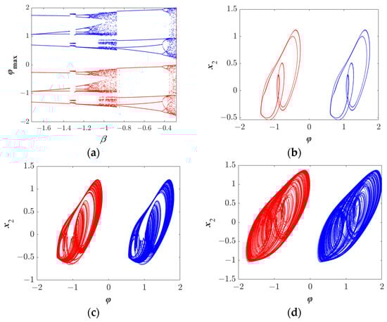
Figure 6.
Coexistence phenomenon caused by initial values (blue: (0, 0, 0, 1), red: (0, 0, 0, −1)): (a) Coexistence bifurcation diagram; and coexistence attractors under different parameter conditions (b) β = −1.2, (c) β = −1, (d) β = −0.29.
The study of symmetry in neural networks holds fundamental significance. It enhances system stability, simplifies analytical procedures, and improves memory storage capacity and robustness. Keeping all other system parameters constant, changing the flux function of the memristor from W(φ) = 1 + sin(πφ) to W(φ) = 1 − sin(πφ) results in a symmetric bifurcation diagram, as illustrated in Figure 7a. In this diagram, the state variable φ is symmetrically distributed with respect to the horizontal axis, indicating that the system possesses two symmetric solutions under the corresponding conditions. Figure 7b–d depict the attractor structures under different parameter settings, which also exhibit clear symmetric characteristics. Specifically, these attractors are symmetric about the φ-axis; that is, for a given value of φ, there exists a corresponding value of −φ with the same x2 value. This symmetry arises from the mathematical invariance of the system under the transformation φ → −φ and the corresponding adjustment of the W function: the solution of the modified system corresponds to the mirror image of the original solution along the negative axis. This symmetric property highlights one of the core advantages of HNNs. It not only simplifies computational and design processes but also deepens our understanding of the system’s dynamic behavior, stability, and application potential. During practical research, actively exploring and utilizing symmetry can accelerate the discovery of novel phenomena and optimize network performance, constituting an essential component of the HNN theoretical framework.
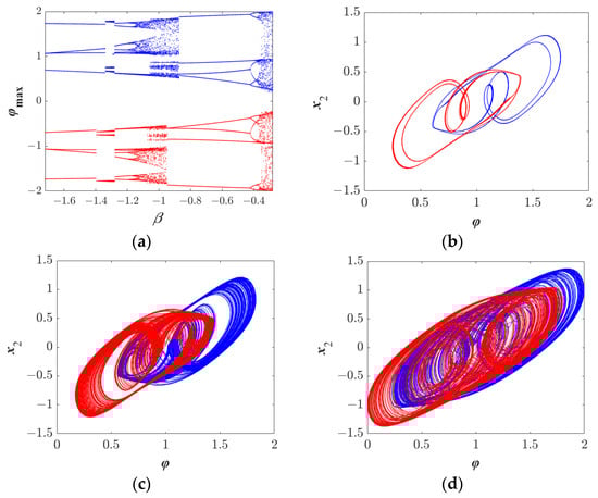
Figure 7.
Symmetric phenomenon caused by initial values (blue: (0, 0, 0, 1), red: (0, 0, 0, −1)): (a) Symmetric bifurcation diagram; and symmetric attractors under different parameter conditions (b) β = −1.2, (c) β = −1, (d) β = −0.29.
3.5. Analysis of the Robustness to Initial Values and Transient Chaotic Characteristics
In the study of chaotic systems, the constant chaotic characteristic is defined as the persistent manifestation of chaotic behavior within a specific domain of initial conditions, reflecting robustness to perturbations in the initial values. This section investigates this property through numerical simulations. Specifically, while keeping other parameters constant, we set β = 0.18 and the initial condition IC = (0, 0, 0, φ0), where φ0 varies within the range [−106, 106]. Figure 8a demonstrates that regardless of the value of φ0, the bifurcation trajectory of the system state variable x1 consistently remains in a chaotic oscillation state, with no periodic windows or stable fixed points observed. This confirms that the system exhibits the constant chaotic characteristic, i.e., robustness to initial value perturbations. Furthermore, this conclusion can be corroborated by analyzing the Lyapunov exponent spectrum. As illustrated in Figure 8b, the maximum Lyapunov exponent (LE1) remains positive throughout, aligning with the diagnostic criterion for chaotic systems. This behavior originates from the positive feedback coupling mechanism between the nonlinear memory effect of the memristor and electromagnetic radiation, which ensures the structural stability of the chaotic attractor domain even under initial phase perturbations.

Figure 8.
Simulation diagrams of the characteristics of constant chaos and transient chaos: (a) bifurcation diagram of constant chaos, (b) Lyapunov exponent diagram of constant chaos, (c) time series corresponding to transient chaos, and (d) phase diagram of transient chaos attractors.
In addition to its constant chaotic characteristics, the system also exhibits transient chaotic phenomena. Specifically, it displays chaotic behavior within a limited time frame before gradually transitioning to a stable state, such as a periodic orbit. When the system parameter β is set to −0.8 and all other parameters remain constant, with the initial condition IC = (0, 0, 0, 1), the dynamic behavior of the system can be divided into two distinct stages. During the early oscillatory phase (t < 280), the system demonstrates typical chaotic attractor characteristics, as illustrated in the blue portion of Figure 8c. At this stage, the system’s state is highly sensitive to the initial conditions, and even minor disturbances can result in markedly different evolutionary trajectories. As the simulation time progresses (t ≥ 280), the chaotic behavior diminishes and ultimately converges to a stable periodic attractor, as depicted in the red portion of Figure 8c. The phase diagrams of the attractors at different stages are presented in Figure 8d, where the blue segment corresponds to the chaotic attractor for t < 280, and the red segment corresponds to the periodic attractor for t ≥ 280. These findings indicate that the system’s transient chaotic behavior is confined to a specific time interval, after which it evolves into a deterministic steady state. This phenomenon suggests that by appropriately tuning the system parameters, transient chaos can be effectively induced or suppressed, offering novel insights for chaos control and in practical applications.
3.6. Attractor Shift Behavior Induced by Internal Parameters of the Memristor
In this section, by adjusting the memristor parameters a and b, the M-HNN exhibits the phenomenon of attractor shift, which is verified through the average value graph and phase diagrams. With all other parameters listed in Table 1 remaining constant, set the initial condition IC = (0, 0, 0, 1). When parameter a increases within the range [0, 8], the changes in the average values of the system state variables can be plotted, as shown in Figure 9a. From Figure 9a, it is evident that the average values of the state variables x1, x2, and x3 remain unchanged, whereas the average value of the internal parameter φ of the memristor increases linearly. This indicates that the shape of the attractor in the φ direction remains invariant. However, its position will shift as variable a increases. Figure 9b illustrates the attractor phase diagrams corresponding to different values of a. Specifically, as a increases, the attractor shifts along the φ axis, which aligns with the analysis presented in Figure 9a.
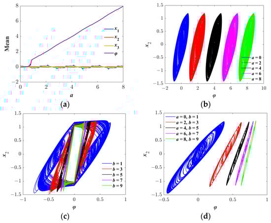
Figure 9.
Attractor shift behaviors induced by the change in internal parameters of the memristor: (a) the average values of system variables when a∈[0, 8], (b) attractor phase diagrams for different a values, (c) attractor phase diagrams for different b values, (d) attractor phase diagrams corresponding to simultaneous changes in a and b.
Furthermore, the internal parameter b of the memristor also has a significant impact on the shape of the attractor of the system. As shown in Figure 9c, when the parameter b changes, the shape of the attractor mainly shows a scaling effect. Specifically, as b increases, the length of the attractor in the φ direction gradually shortens, presenting an overall compressed trend. The fundamental reason for this phenomenon lies in the fact that parameter b directly affects the resistance value of the memristor, thereby changing the dynamic characteristics of the system. When b is small, the resistance value of the memristor is low, and the system is more likely to produce larger changes in the state variables, thereby forming a longer attractor. However, when b is large, the resistance value of the memristor is high, and the changes in the system state variables are suppressed, resulting in a shortened attractor length. It is worth noting that the change in parameter b does not cause the translation of the attractor, and its position in the φ direction remains unchanged, which is different from the mechanism of action of parameter a.
Figure 9d illustrates the combined influence of parameters a and b on the system attractors. As observed from the figure, the simultaneous adjustment of parameters a and b results in two distinct effects on the attractor: translation and scaling. Specifically, an increase in parameter a induces the translational movement of the attractor in the φ direction. Meanwhile, an increase in parameter b leads to a reduction in the length of the attractor in the φ direction. This dual effect enhances the system’s flexibility, allowing for precise control over both the position and shape of the attractor. By appropriately tuning parameters a and b, the attractors can be finely controlled to accommodate the requirements of various application scenarios.
4. Hardware Implementation
The general-purpose programmable DSP chip is widely utilized in the implementation of chaotic systems due to its capability to efficiently process complex digital signal algorithms. However, continuous-time chaotic systems cannot be directly executed on the DSP platform and must therefore be discretized. Common discretization methods include the Euler method, the improved Euler method, and the Runge–Kutta method, among others. Considering the high demand for iteration speed in DSP systems, this paper selects the simple Euler algorithm, which has a lower computational complexity, to achieve the discretization of the chaotic system. Based on the Euler discretization method, Equation (5) can be transformed into the following form:
Among them, the integral step is set as Δt = 0.01. State variables (x1, x2, x3, φ) are stored in 32-bit floating-point arrays (256 KB RAM allocation) with double-buffering to decouple the computation and DAC output. The digital signal processing (DSP) platform used in the experiment is the ICETEK-VC5509A evaluation board, and its core DSP chip is TMS320C5509 operating at 100 MHz. The fixed sampling rate of 10 kHz (validated by Tektronix DSO-X3034A) ensures real-time chaos generation. The experimental results are converted into analog signals through the TLC7528C D/A converter introducing ±0.39% quantization error and are displayed and analyzed by the Tektronix DSO-X3034A oscilloscope. It should be noted that since the data bit width of the used D/A converter is 8 bits, before transmitting the signals to the D/A converter, all input signals must undergo scaling processing via the affine transformation Vout = 12.75(10 + xi) to maximize dynamic range and be converted into unsigned 8-bit integers within the range of [0, 255].
In the experiment, the initial condition was set to IC = (0, 0, 0, 1), while all other parameters were kept constant. By varying the parameter β, the dynamic behavior of the system under different parameter conditions was systematically investigated. The attractor phase diagram obtained from the experiment is presented in Figure 10a–f. This diagram vividly illustrates the evolution trend of the system under varying parameter conditions. The study reveals that the experimental data are in excellent agreement with the simulation results, thereby providing further validation of the system’s dynamic characteristics.
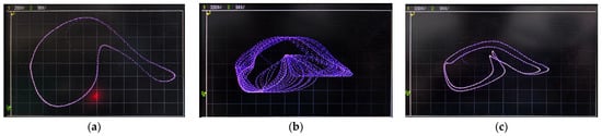
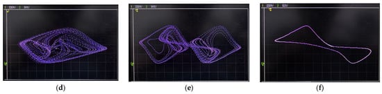
Figure 10.
Experimental results from DSP hardware: (a) Single-period attractor, (b) chaotic attractor, (c) multiple-period attractor, (d) chaotic attractor, (e) double-scroll chaotic attractor, and (f) single-period attractor.
Furthermore, an experimental verification study was conducted regarding the characteristics of coexisting attractors in the system as well as the phenomena of attractor position offset and scaling. As illustrated in Figure 11a–d, the experimental results clearly corroborated these phenomena. The corresponding experimental setup is depicted in Figure 11e. Under varying parameter settings and initial conditions, the experimental outcomes exhibited a high degree of consistency with numerical simulations, thereby effectively validating the accuracy of the theoretical analysis.
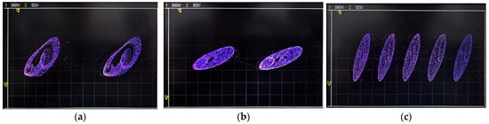
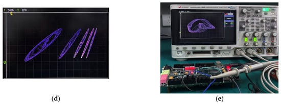
Figure 11.
Hardware implementation results based on DSP: (a,b) Coexisting attractors under different initial value conditions, (c,d) attractor translation and scaling phenomena under different parameter conditions, and (e) the corresponding experimental device.
5. Conclusions
This paper introduces a novel memristor-based electromagnetic radiation hybrid neural network, which aims to combine the distinctive nonlinearity of memristors with the computational strengths of traditional neural networks. To gain deeper insights into the dynamic behavior of this model, we utilize a variety of theoretical and numerical analysis tools, including phase diagrams, bifurcation diagrams, and Lyapunov exponent spectra, to perform a thorough examination of its equilibrium points and complex dynamic characteristics. The research findings indicate that when the M-HNN is exposed to electromagnetic radiation, it displays a wealth of nonlinear dynamic phenomena, such as coexisting attractors, transient chaos, and attractor shifts. By systematically tuning parameters in the memristor and the intensity of the electromagnetic radiation, significant alterations in the system’s dynamic characteristics are observed. We demonstrate that the M-HNN under electromagnetic radiation exhibits over 12 distinct attractors and expands chaotic regimes to g13 ∈ [4.1, 8.7]∪[10.7, 12.5] (933% wider than that of the baseline HNN [2.2, 2.8]). To validate the numerical simulation results, we construct a digital hardware platform based on DSP and successfully replicate the intricate dynamic behaviors identified through theoretical analysis and numerical simulations, thereby affirming the reliability of our conclusions. Despite successful DSP validation, potential chaos degeneration from discretization motivates future analog circuit implementation for enhanced fidelity. The demonstrated transient chaos and multi-attractor dynamics show strong potential for secure communication applications.
Author Contributions
Data curation, X.W.; Formal analysis, H.Z. and Y.Q.; Funding acquisition, M.Y.; Investigation, H.Z.; Software, M.Y.; Writing—original draft, Z.G. and Y.Q.; Writing—review and editing, B.H., M.Y., X.W. and H.Z. All authors have read and agreed to the published version of the manuscript.
Funding
This research was funded by the National Key Research and Development Program of China, grant numbers 2022XXX2808004 and 2023YFC2809605.
Data Availability Statement
The original contributions presented in this study are included in the article. Further inquiries can be directed to the corresponding author.
Conflicts of Interest
Zhimin Gu, Bin Hu, Xiaodan Wang, and Min Yang are employed by North China Sea Marine Technology Center, Ministry of Natural Resources (North China Sea Vessel and Aircraft Center, Ministry of Natural Resources). Hongxin Zhang is employed by North China Sea Marine Support Center, Ministry of Natural Resources. The remaining authors declare no potential commercial or financial conflicts of interest.
References
- Zhang, X.; Li, C.B.; Moroz, I.; Huang, K.Y.; Liu, Z.H. Non-bifurcation regulation of chaos in a memristive Hopfield neural network. Nonlinear Dyn. 2025, 113, 15487–15502. [Google Scholar] [CrossRef]
- Zhang, J.; Li, Z.J. Switchable memristor-based Hindmarsh-Rose neuron under electromagnetic radiation. Nonlinear Dyn. 2024, 112, 6647–6662. [Google Scholar] [CrossRef]
- Ma, T.; Mou, J.; Chen, W.Z. Implementation of a cell neural network under electromagnetic radiation with complex dynamics. Nonlinear Dyn. 2025, 113, 18689–18704. [Google Scholar] [CrossRef]
- Fang, Y.; Yaning, Q.; Xiangcheng, Y.; Yue, D. Design and analysis of grid attractors in memristive Hopfield neural networks. Chaos Solitons Fract. 2024, 188, 115478. [Google Scholar]
- Strukov, D.B.; Snider, G.S.; Stewart, D.R.; Williams, R.S. The missing memristor found. Nature 2008, 453, 80–83. [Google Scholar] [CrossRef]
- Yihyis, W.A.; He, S.B.; Tang, Z.Q.; Wang, H.H. A class of discrete memristor chaotic maps based on the internal perturbation. Symmetry 2023, 15, 1574. [Google Scholar] [CrossRef]
- Stremoukhov, S.; Forsh, P.; Khabarova, K.; Kolachevsky, N. Proposal for trapped-ion quantum memristor. Entropy 2023, 25, 1134. [Google Scholar] [CrossRef] [PubMed]
- Yao, P.; Wu, H.Q.; Gao, B.; Tang, J.S.; Zhang, Q.T.; Zhang, W.Q.; Yang, J.J.; Qian, H. Fully hardware-implemented memristor convolutional neural network. Nature 2020, 577, 641–646. [Google Scholar] [CrossRef]
- Zhu, J.Y.; Cao, Y.H.; Mou, J.; Banerjee, S. KTz Neuron in electromagnetic radiation with a novel flux-controlled memristor. Int. J. Bifurc. Chaos 2024, 34, 11. [Google Scholar] [CrossRef]
- Zhang, S.; Peng, X.N.; Wang, X.P.; Chen, C.J.; Zeng, Z.G. A novel memristive multiscroll multistable neural network with application to secure medical image communication. IEEE Trans. Circuits Syst. Video Technol. 2025, 35, 1774–1786. [Google Scholar] [CrossRef]
- Peng, S.; Shi, H.; Li, R.; Xiang, Q.; Dai, S.; Li, Y. Simulink modeling and analysis of a three-dimensional discrete memristor map. Symmetry 2024, 16, 990. [Google Scholar] [CrossRef]
- Cao, H.L.; Cao, Y.H.; Xu, X.Y.; Mou, J. Dynamical analysis of a discrete Aihara neuron under a locally active memristor as electromagnetic radiation and its DSP implementation. Phys. Scr. 2024, 99, 085226. [Google Scholar] [CrossRef]
- Hu, X.Y.; Liu, C.X.; Liu, L.; Ni, J.K.; Yao, Y.P. Chaotic dynamics in a neural network under electromagnetic radiation. Nonlinear Dyn. 2018, 91, 1541–1554. [Google Scholar] [CrossRef]
- Chen, C.J.; Min, F.H.; Zhang, Y.Z.; Bao, B.C. Memristive electromagnetic induction effects on Hopfield neural network. Nonlinear Dyn. 2021, 106, 2559–2576. [Google Scholar] [CrossRef]
- Lin, H.R.; Wang, C.H.; Tan, Y.M. Hidden extreme multistability with hyperchaos and transient chaos in a Hopfield neural network affected by electromagnetic radiation. Nonlinear Dyn. 2020, 99, 2369–2386. [Google Scholar] [CrossRef]
- Tamba, V.K.; Ngoko, G.; Pham, V.T.; Grassi, G. Chaos, Hyperchaos and transient chaos in a 4D Hopfield neural network: Numerical analyses and PSpice implementation. Mathematics 2025, 13, 1872. [Google Scholar] [CrossRef]
- Jin, P.P.; Han, N.N.; Zhang, X.F.; Wang, G.Y.; Chen, L. Edge of Chaos Kernel and neuromorphic dynamics of a locally-active memristor. Commun Nonlinear Sci Numer Simul 2023, 117, 106961. [Google Scholar] [CrossRef]
- Yu, F.; Shen, H.; Zhang, Z.N.; Huang, Y.Y.; Cai, S.; Du, S.C. Dynamics analysis, hardware implementation and engineering applications of novel multi-style attractors in a neural network under electromagnetic radiation. Chaos Solitons Fractals 2021, 152, 111350. [Google Scholar] [CrossRef]
- Wan, Q.Z.; Yan, Z.D.; Li, F.; Liu, J.; Chen, S.M. Multistable dynamics in a Hopfield neural network under electromagnetic radiation and dual bias currents. Nonlinear Dyn. 2022, 109, 2085–2101. [Google Scholar] [CrossRef]
- Wan, Q.Z.; Chen, S.M.; Liu, T.Q.; Lan, H.X.; Shen, K. A novel locally active memristive autapse-coupled Hopfield neural network under electromagnetic radiation. Integration 2025, 103, 102410. [Google Scholar] [CrossRef]
- Kong, X.X.; Yu, F.; Yao, W.; Cai, S.; Zhang, J.; Lin, H.R. Memristor-induced hyperchaos, multiscroll and extreme multistability in fractional-order HNN: Image encryption and FPGA implementation. Neural Netw. 2024, 171, 85–103. [Google Scholar] [CrossRef]
- Lai, Q.; Yang, L. Hyperchaos of neuron under local active discrete memristor simulating electromagnetic radiation. Chaos 2024, 34, 013145. [Google Scholar] [CrossRef]
- Zhang, S.; Zheng, J.H.; Wang, X.P.; Zeng, Z.G. Multi-scroll hidden attractor in memristive HR neuron model under electromagnetic radiation and its applications. Chaos 2021, 31, 011101. [Google Scholar] [CrossRef] [PubMed]
- Zhang, S.; Li, C.B.; Zheng, J.H.; Wang, X.P.; Zeng, Z.G.; Chen, G.R. Memristive autapse-coupled neuron model with external electromagnetic radiation effects. IEEE Trans. Ind. Electron. 2023, 70, 11618–11627. [Google Scholar] [CrossRef]
- Tamba, V.K.; Pham, V.T.; Volos, C. A simple third-order Hopfield neural network: Dynamic analysis, microcontroller implementation and application to random number generation. Symmetry 2025, 17, 330. [Google Scholar] [CrossRef]
- Sun, J.W.; Zhao, Y.; Li, C.C.; Wang, Y.F.; Liu, P. Dynamical analysis of memristive HNN and medical image encryption via bi-directional permutation and multi-directional diffusion to PACS. IEEE Trans. Circuits Syst. I 2024, 71, 5734–5744. [Google Scholar] [CrossRef]
Disclaimer/Publisher’s Note: The statements, opinions and data contained in all publications are solely those of the individual author(s) and contributor(s) and not of MDPI and/or the editor(s). MDPI and/or the editor(s) disclaim responsibility for any injury to people or property resulting from any ideas, methods, instructions or products referred to in the content. |
© 2025 by the authors. Licensee MDPI, Basel, Switzerland. This article is an open access article distributed under the terms and conditions of the Creative Commons Attribution (CC BY) license (https://creativecommons.org/licenses/by/4.0/).