Article

More Diagonal Distributions of Coexisting Attractors

by
Menghui Shen
1,
Chunbiao Li
1,2,*,
Lili Wang
3,
Yishi Xue
4 and
Xiaolong Qi
5
1
School of Electronic and Information Engineering, Nanjing University of Information Science & Technology, Nanjing 210044, China
2
School of Artificial Intelligence, Nanjing University of Information Science & Technology, Nanjing 210044, China
3
School of Electronic and Information Engineering, Anhui Jianzhu University, Hefei 230009, China
4
Department of Computer Information and Cyber Security, Jiangsu Police Institute, Nanjing 210031, China
5
School of Network Security and Information Technology, Yili Normal University, Yining 835000, China
*
Author to whom correspondence should be addressed.
Symmetry 2025, 17(8), 1331; https://doi.org/10.3390/sym17081331
Submission received: 29 July 2025 / Revised: 9 August 2025 / Accepted: 12 August 2025 / Published: 15 August 2025
(This article belongs to the Section Engineering and Materials)

Abstract

When periodic and other piecewise linear functions are introduced in a chaotic system with two-dimensional offset boosting for extra feedback, more patterns of diagonal distribution from coexisting attractors can be organized. In this study, the periodic function is implanted for attractor self-reproducing, while the signum function and absolute value function are integrated for the attractor symmetrization. For the offset interlocking across dimensions, the coexisting attractors can be reproduced in phase space with the shapes of “V” and “X”. Based on the FPGA platform, all the patterns are validated in a digital hardware environment confirming the consistency with simulation.

1. Introduction

Chaos, as a complex phenomenon in nonlinear dynamical systems, is widely found in both natural environments and engineering systems [1]. Although the evolution of a chaotic system is characterized by high uncertainty and unpredictability, it is governed internally by strict deterministic law. This property of “deterministic disorder” has been recognized to be of significant value in a wide range of cutting-edge fields, including chaos-based communication [2,3,4], image processing [5,6,7], and biomedical applications [8,9]. In recent years, memristors have shown potential in neuromorphic computing and secure communications due to their unique nonlinear characteristics, offering new possibilities for the circuit implementation and functional extension of chaotic systems [10,11].
Offset boosting, as an effective means of regulating the behavior of chaotic systems, allows for flexible switching between bipolar and unipolar chaotic signals without requiring complex modifications to the system [12]. By introducing an independent constant into the system and precisely setting initial conditions, the system variable can be selectively shifted to targeted regions, thereby forming different distribution patterns within specific planes when a corresponding function is introduced [13]. This offset-oriented approach not only enhances the dynamic controllability of chaotic systems but also increases their application value in fields such as signal processing, secure communications, and random number generation [14,15,16]. To further achieve efficient offset regulation avoiding an increase in the number of system feedback, a periodic function or absolute value function has been introduced as the core channel for organizing coexisting attractors. Through this mechanism, free offset boosting in the two-dimensional plane can be realized simply by appropriately adjusting the initial values and selecting offset function. This design not only simplifies the system structure but also provides an efficient and practical solution for multidimensional chaos control.
Based on the combination of periodic functions and non-smooth piecewise linear functions, the coexisting attractors of a system can be defined with richer distribution patterns. Signature functions are introduced for enabling attractor doubling within the phase space. The specific phenomenon of multistability refers to the coexisting multiple stabilities governed by different initial conditions under an identical set of system parameters [17,18,19]. Different patterns of attractor distribution can be caught by the selection of offset functions. Li et al. [20] demonstrated that by introducing periodic functions, an infinite two-dimensional lattice of coexisting attractors could be coined, indicating the spatial distribution regulation based on the operation of initial value-dependent offset boosting. In this work, a chaotic system is equipped with different offset functions to form different attractor distributions in the phase space, notably for the first time; specific tilted-1-shaped, V-shaped and X-shaped attractor distribution are realized, indicating the high degree of diversity and complexity of the multistability in a dynamical system. To verify the effectiveness of offset-oriented feedback, hardware implementation was carried out based on the FPGA platform [21,22].
In the following, the work is organized as follows: in Section 2, the basic 1-shaped coexisting attractors are obtained from a chaotic system with a two-dimensional system. In Section 3, V-shaped and X-shaped coexisting attractors are coined with the support of a piecewise linear function, the mechanism of which is also examined. In Section 4, FPGA-based circuit implementation is developed, where the diagonal distributions of coexisting attractors are verified. The main conclusions are summarized in the last section.

2. Single-Line Distributed Coexisting Attractors

For regulating the coexisting attractors, a three-dimensional chaotic system with interlocked two-dimensional offset boosting [23] was selected for its structural simplicity and flexible offset boosting, and ultimately became the candidate for multistability design:
x ˙ = 1 a z y ˙ = b z 2 y z ˙ = x y
System (1) is a variable-boostable chaotic system when a = 3.9, b = 3.5. For realizing the attractor reproducing along the x-dimension, the tangent function of x is introduced. A single trigonometric function of the variable x can be introduced as follows:
x ˙ = 1 a z y ˙ = b z 2 y z ˙ = c tan ( d x ) y
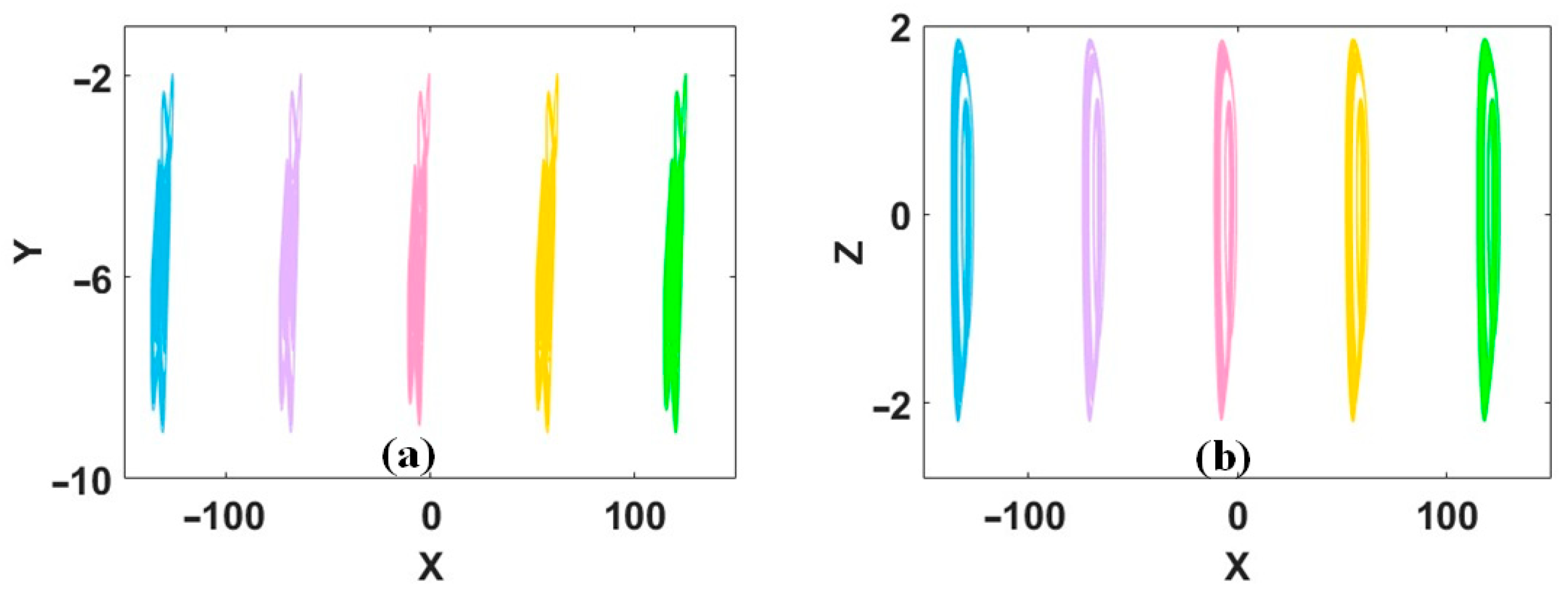
When a = 3.9, b = 3.5, c = 19, and d = 0.05, System (2) has chaotic solution with Lyapunov exponents of (0.0305, 0, −1.0306), and the Kaplan–Yorke dimension of 2.0296, as shown in Figure 1. For the period of feedback, infinitely many 1-shaped coexisting attractors are born in System (2), as shown in Figure 2, where the combinations of the parameter c and d modify the attractor type and the interval among any two coexisting attractors. Here, the multiple initial conditions (IC) used in Figure 2 are essential for the generation of coexisting attractors. The selection of initial conditions is based on the original one for chaos with the modification of periodic coexisting attractors.
Tilted-1-shaped coexisting attractors can be obtained via two-dimensional offset boosting [24]. Based on the interlocked internal linear relationship, a single periodic function can realize attractor self-reproducing.
x ˙ = 1 a z y ˙ = b z 2 9.6 tan ( 0.1 y ) z ˙ = x y
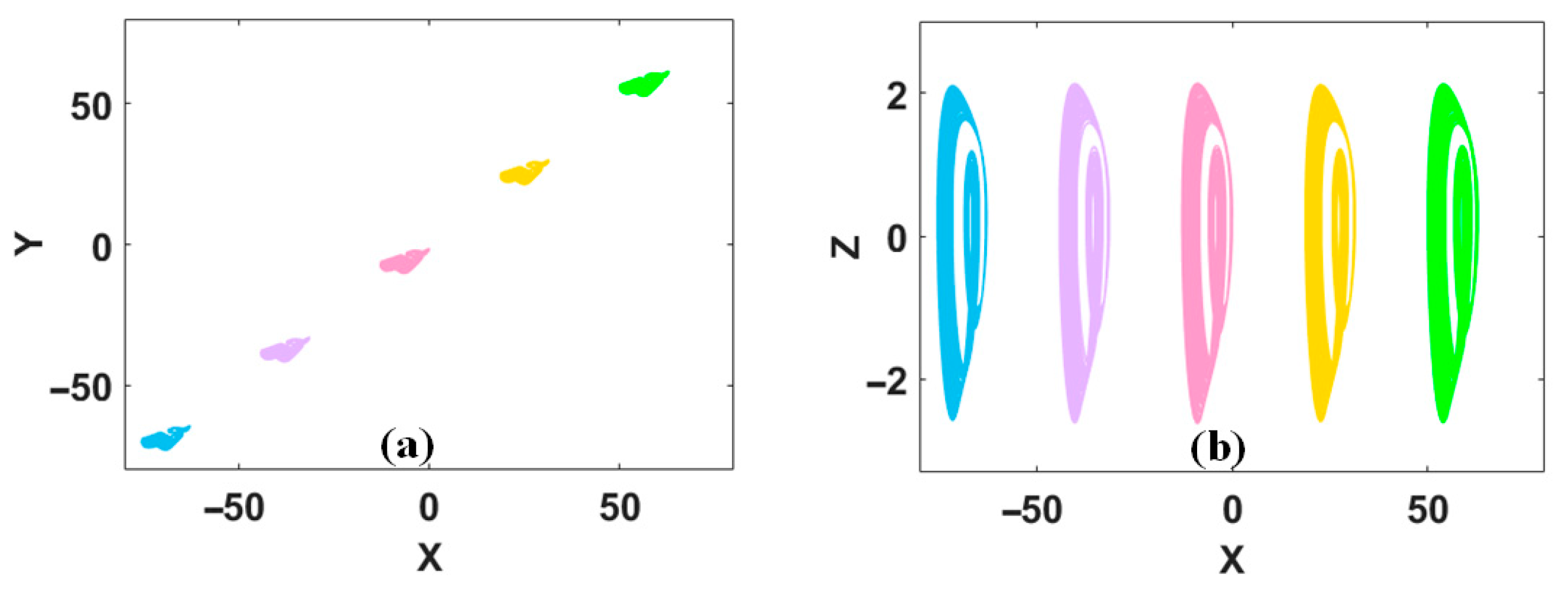
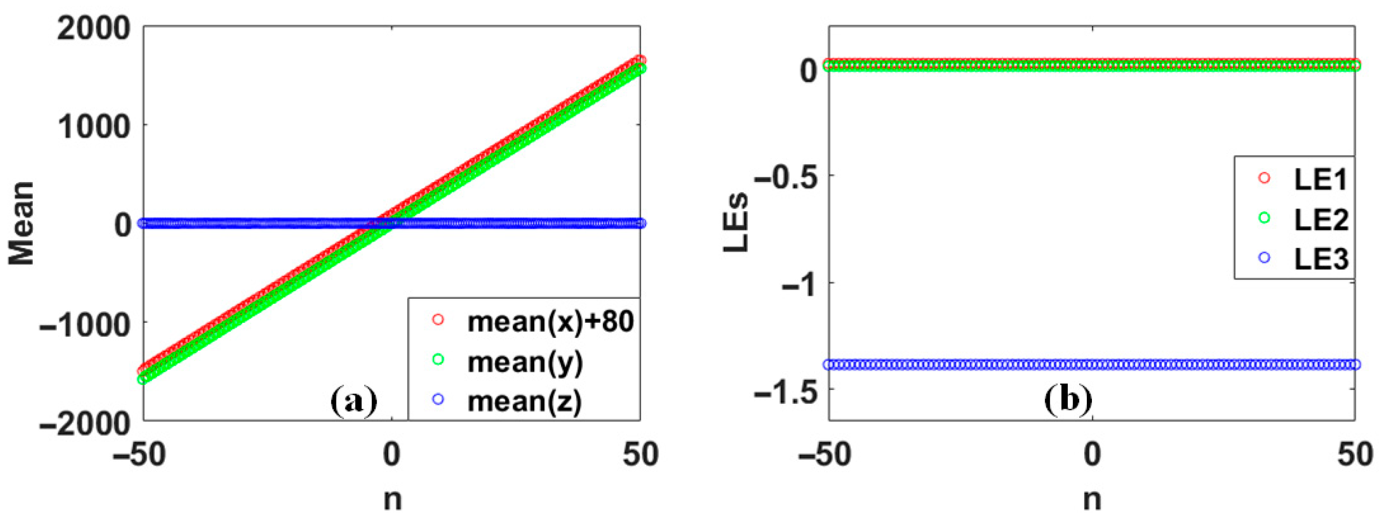
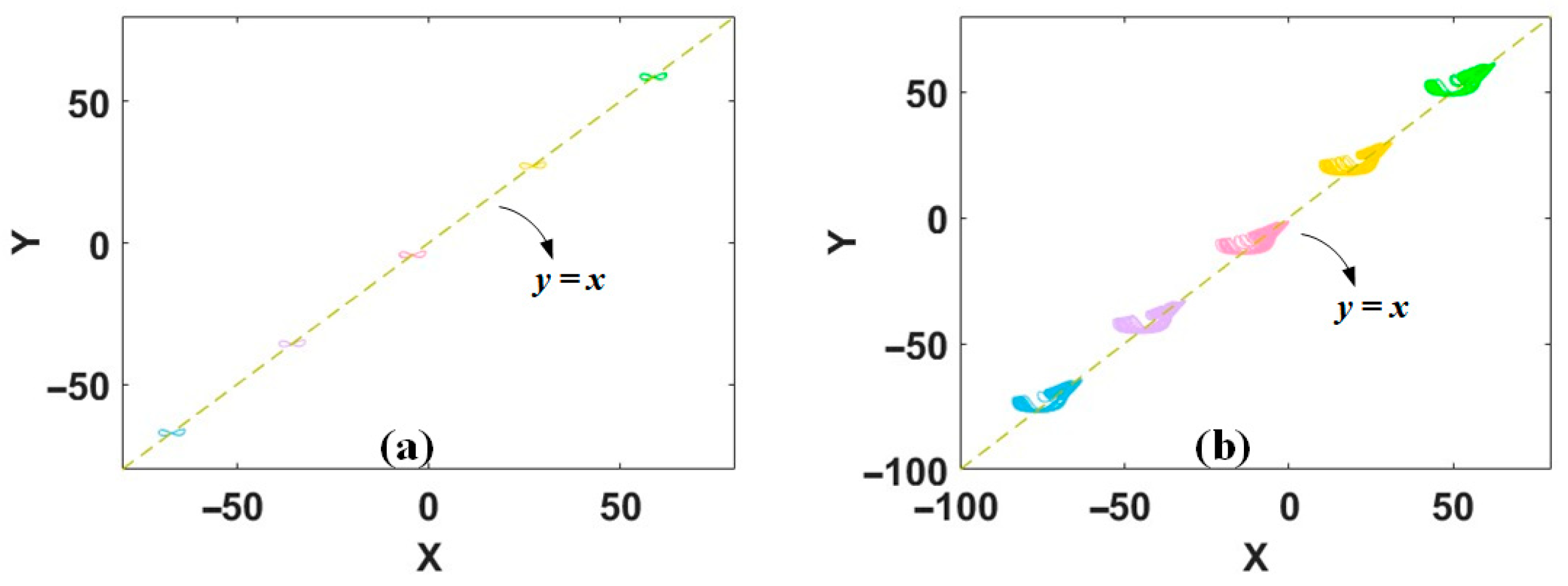
Here, System (3) is derived from System (2) by modifying the introducing of the periodic function, which generates the tilted-1-shaped coexisting attractors rather than standard-1-shaped attractors. When a = 3.9, b = 3.5, and the initial conditions are (−9, −8, 0), the system exhibits chaos with Lyapunov exponents of (0.0098, 0, −1.3242), and the Kaplan–Yorke dimension of 2.0074, as shown in Figure 3. Periodic feedback brings infinitely many stable foci S0 (10, 10, 0) (n ∈ Z) in System (3) with eigenvalues of λ1 = −0.96, λ2 = −1.9748i, and λ3 = 1.9748i, which, in turn, receives the dynamics reproduced, forming tilted-1-shaped coexisting attractors as shown in Figure 4. As predicted, like the 1-shaped coexisting attractors, all the tilted-1-shaped coexisting attractors share identical Lyapunov exponents but display increasing average values of x and y, as shown in Figure 5.
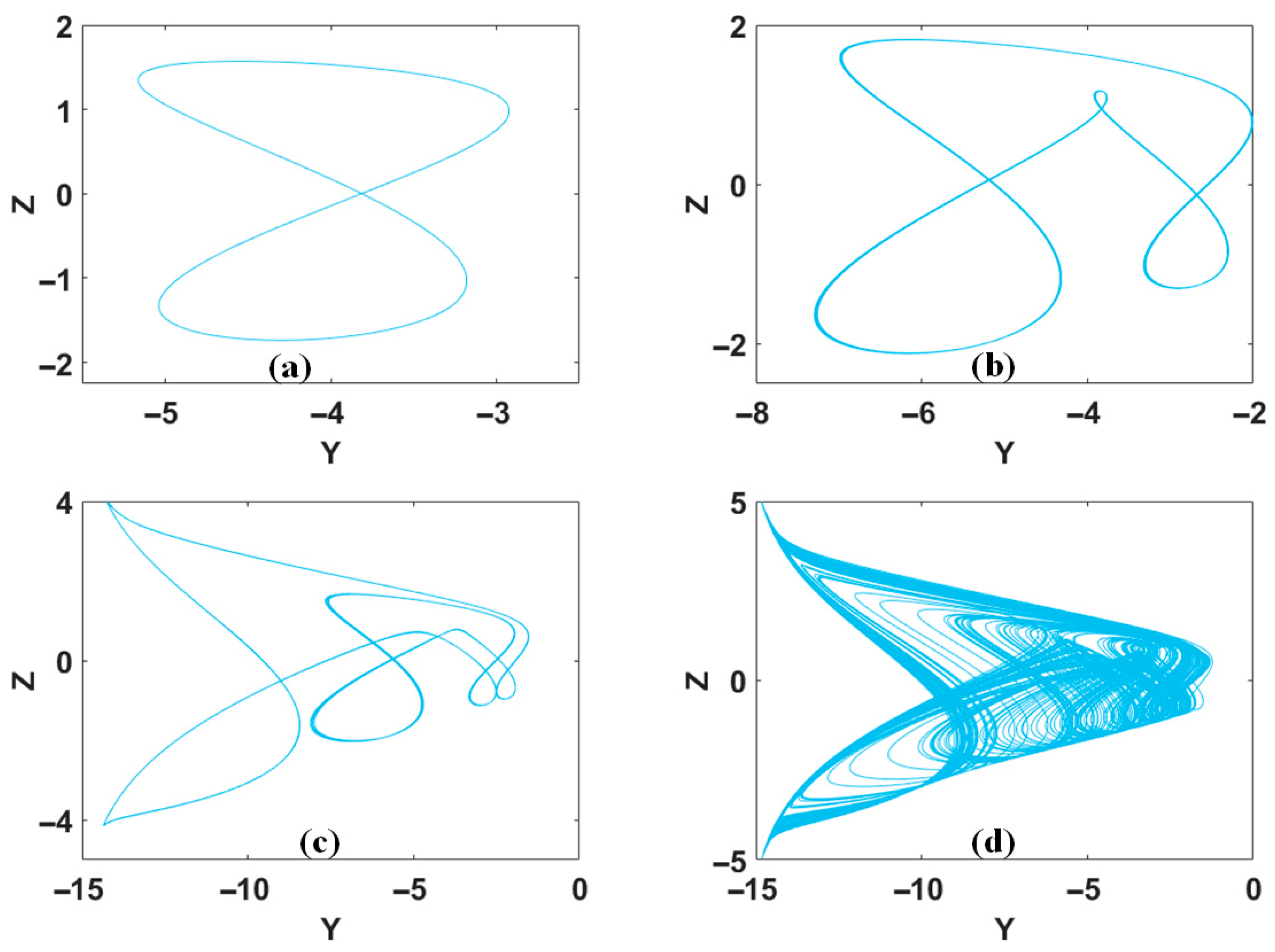
Here, the bifurcation parameter b in System (3) will revise the dynamics of the coexisting attractors without influencing the intervals governed by the periodic tangent function. All the possible periodic and chaotic oscillations, like those plotted in Figure 6, can be reproduced under the tilted-1-shaped distribution, as shown in Figure 7. The specific values of b were selected based on the analysis of Lyapunov exponents and bifurcation diagrams, aiming to demonstrate the evolution of coexisting attractors of period to chaos. Here, the distribution of the coexisting attractors is independent with the parameter b.
If the type of coexisting attractors needs to be fixed, but the slope of the tilted-1-shaped distribution is to be modified, a non-bifurcation amplitude controller can be introduced here. Suppose x→1/k x, Equation (3) can be transformed into Equation (4):
x ˙ = ( 1 a z ) / k y ˙ = b z 2 9.6 tan ( 0.1 y ) z ˙ = k x y
With the rescaling of the attractor in the dimension of x, all the coexisting attractors are organized with different slopes of tilted-1-shaped distribution. Note that here, the coexisting attractors have different sizes in the dimension of x according to the parameter k. As shown in Figure 8, with the increase in initial conditions of x and y, the average value of x changes accordingly.

3. V-Shaped and X-Shaped Coexisting Attractors

To systematically control the distribution of coexisting attractors, more piecewise linear functions can be introduced for multistability design. By incorporating the offset function, the chaotic attractors can be doubled by an absolute value function. By setting x→|x| − c and thus introducing a signum function sgn(x) into the first dimension, System (3) can be reformulated as follows:
x ˙ = sgn ( x ) ( 1 a z ) y ˙ = b z 2 9.6 tan ( 0.1 y ) z ˙ = x c y
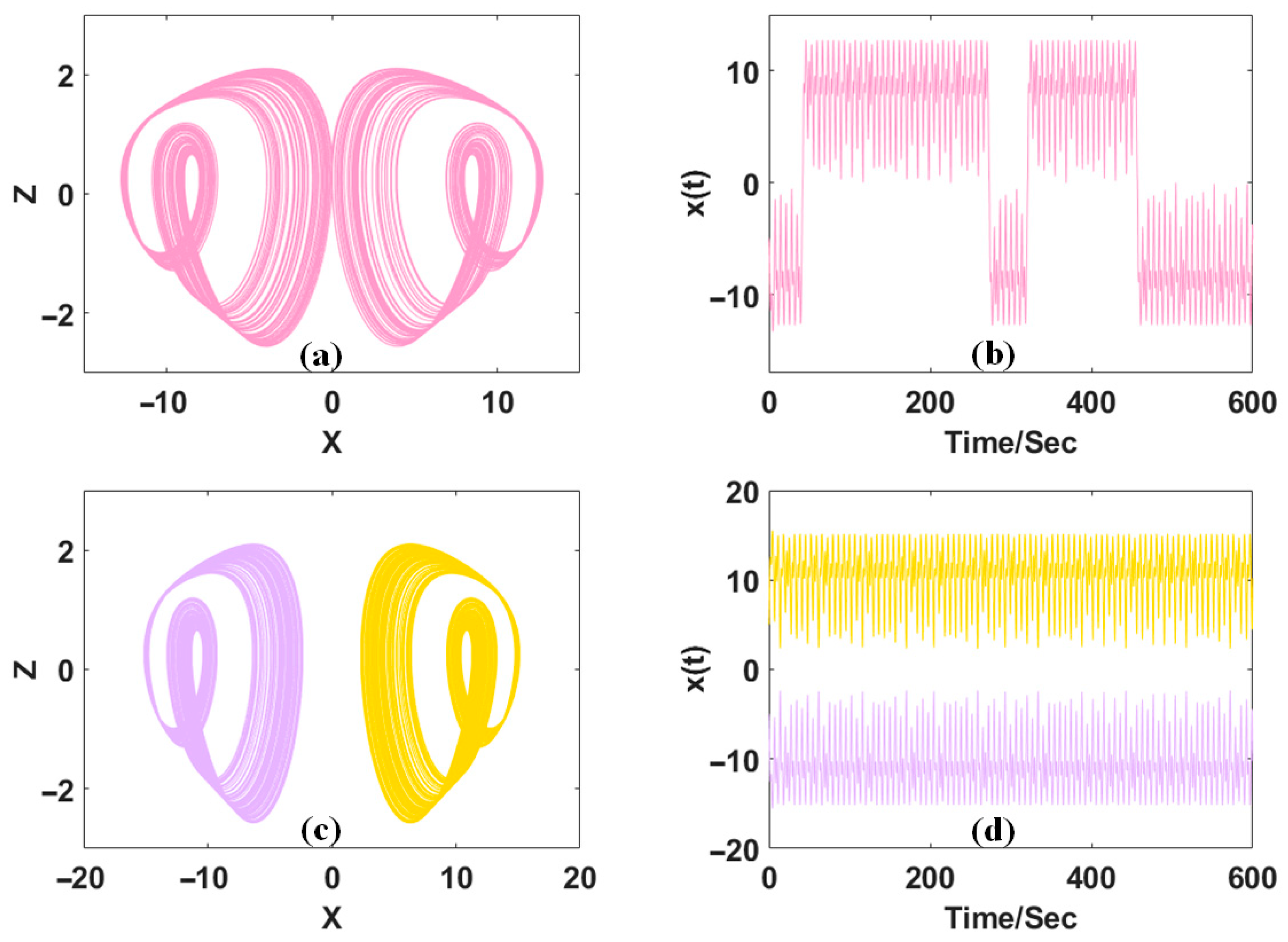
In this time, the chaotic attractor will become doubled according to the controller c. The larger parameter c will make the coexisting attractors separate with wider distance while the smaller c may put the coexisting attractors closer, forming a pseudo-double-scroll attractor in the principal interval of periodic trigonometric function, as shown in Figure 9.
The generation of the pseudo-multi-scroll attractor depends on the coupling of coexisting symmetric attractors under critical offset boosting. By selecting the offset parameter c, two coexisting independent attractors move towards each other closely until their trajectories intertwine and finally form a unique unity. The dominant power hidden behind this formation is from the operation of the absolute value function, where the adjustable offset parameter c defines the distance between any of the two attractors. However, when the attractor self-reproducing happens by the periodic modulation of tan(y), the pseudo-double-scroll structure breaks into two independent scrolls located along the line and defined by the absolute value function.
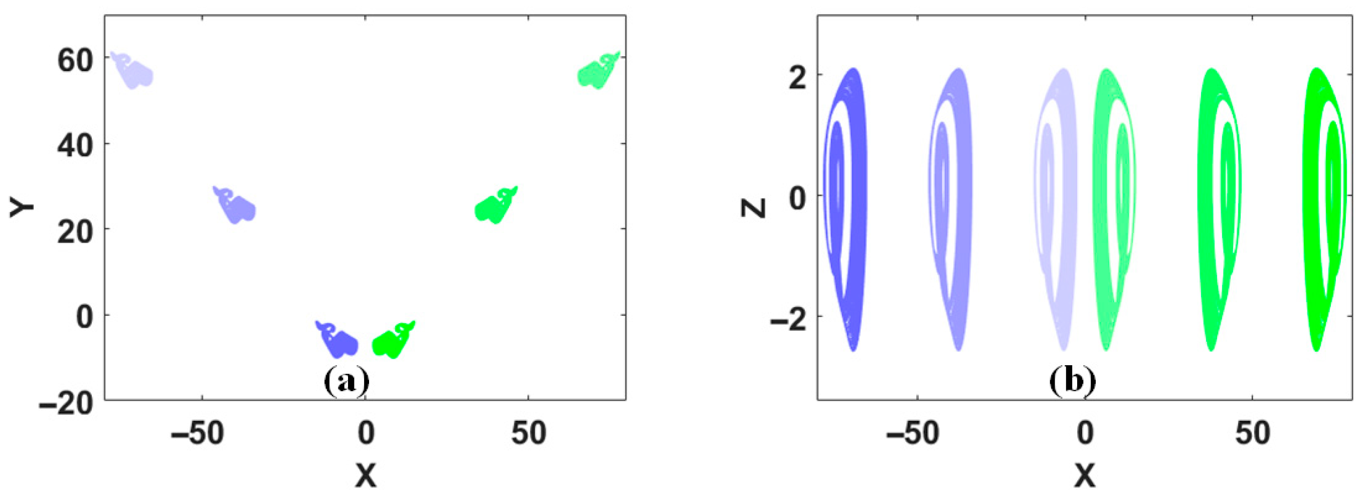
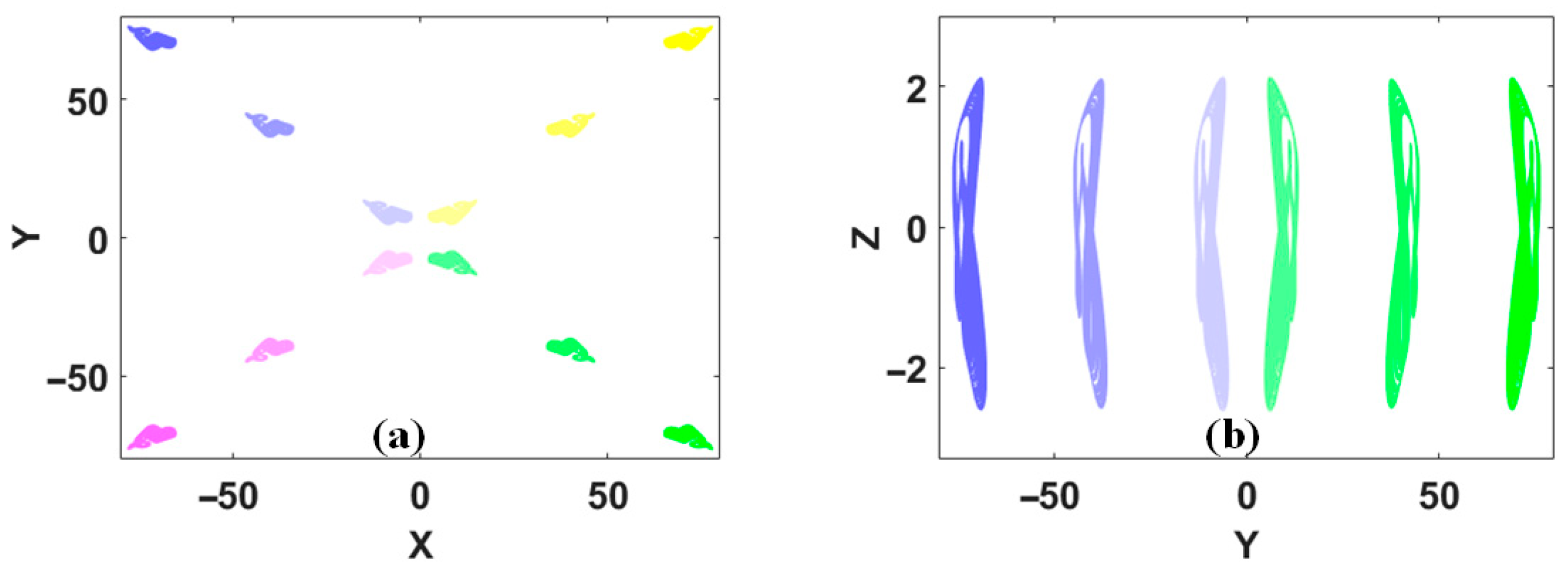
In fact, for the periodicity of the tangent function, attractor self-reproducing happens in the dimension of y, which, in turn, needs an offset cooperation in the dimension of x. Meanwhile, the operation of symmetrization obtains all these doubled coexisting attractors forming a pattern of V-shaped distribution. As shown in Figure 10, these coexisting attractors are symmetrically arranged on both sides of the x-axis. Due to the operation of the absolute value function, any negative offset boosting in the dimension of x gives fixed positive feedback, thus driving the similar response of y and z. Here, the distinctive V-shaped distribution of coexisting attractors is born from the periodic tangent feedback and the operation of the absolute value of x.
Let us take a clear observation of the coexisting attractors. Firstly, the attractors are reproduced with the help of the periodic function of tan(y), where repeated offset boosting brings infinitely many coexisting attractors with a period of 10nπ. The introduction of |x| − c does not alter the periodicity governed by tan(y); instead, it brings symmetry and adjusts the location of the attractors in the dimension of x. As shown in Figure 11, the coexisting attractors stand in phase space along the line of y = |x| − c; meanwhile, the period in the dimension of x remains the same. Furthermore, the parameter c adjusts the distance between any two doubled coexisting attractors. As shown in Figure 12, when the offset c increases, the coexisting attractors are set far apart from each other. All these coexisting attractors share a unified set of Lyapunov exponents. As shown in Figure 13, the combination of the periodic, absolute value, and signum functions regulate the distribution of coexisting attractors and defines the V-shaped distribution.
Attractor doubling can also be simultaneously obtained in many dimensions. For example, two absolute value functions can be employed for two-dimensional doubling. Like the operation in the dimension of x, taking another transformation here in the dimension of y, y→|y| − d and introducing the signum function sgn(y) in the second dimension,
x ˙ = sgn ( x ) ( 1 a z ) y ˙ = sgn ( y ) ( b z 2 9.6 tan ( 0.1 ( y d ) ) ) z ˙ = ( x c ) ( y d )
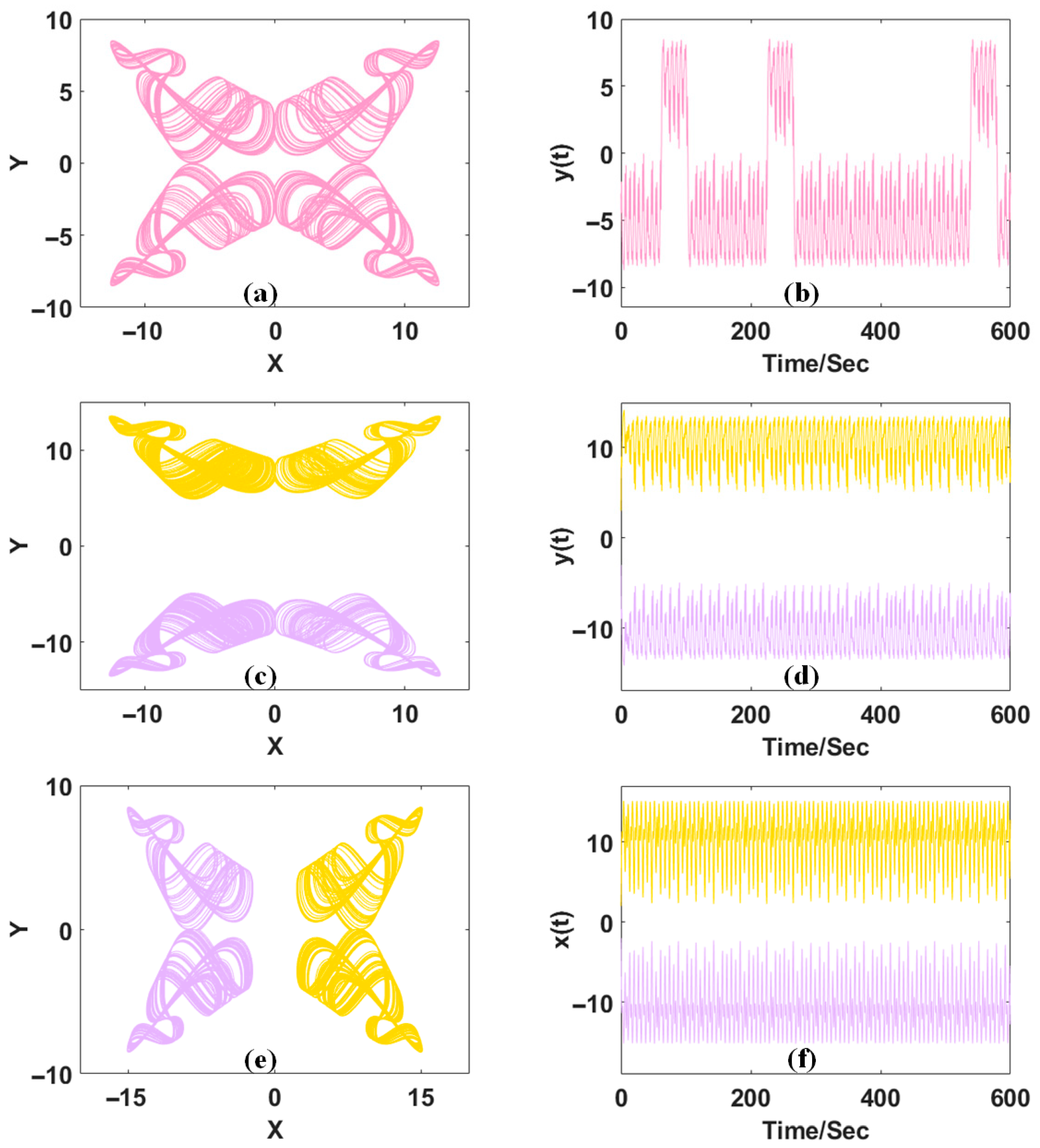
Thus, attractor doubling happens in both the x- and y-dimension, which facilitates the formation of pseudo-four-scroll attractors or pseudo-two-scroll attractors under different combinations of c and d, as plotted in Figure 14.
By introducing two signum functions and two absolute functions, the attractor can be doubled twice. Here, the two offset boosters in both dimensions can be canceled as follows:
x ˙ = sgn ( x ) ( 1 a z ) y ˙ = sgn ( y ) ( b z 2 9.6 tan ( 0.1 ( y d ) ) ) z ˙ = x y
In Equation (7), the controller d can adjust the process of attractor doubling. Similarly, after infinitely many coexisting attractors are born by the periodic function, the process of symmetry brings more coexisting attractors exhibiting a distinctive X-shaped distribution in the x-y plane, as shown in Figure 15. This X-shaped distribution originates from the signum functions sgn(x) and sgn(y), which divide the phase space into four quadrants. The offset booster d determines the displacement of the attractors along the diagonal directions, resulting in a symmetric X-shaped arrangement.
Here, the X-shaped distribution of coexisting attractors can be modified by a non-bifurcation parameter k,
x ˙ = 1 k sgn ( x ) ( 1 a z ) y ˙ = sgn ( y ) ( b z 2 9.6 tan ( 0.1 ( y d ) ) ) z ˙ = k x y
Here, a new parameter k is introduced for the rescaling of the system variable x. Here, the coexisting attractors stand in phase space in lines with different slopes. In Figure 16a, the attractors are symmetrically distributed along the directions of y = ±0.5x, forming an X-shaped structure with a relatively wide opening, while in Figure 16b, the distribution turns to the line of y = ±2x, resulting in a narrower opening. In this condition, the non-bifurcation parameter k is for regulating the location of coexisting attractors. Note that with the effective control over the opening angle of the coexisting attractors, all the coexisting attractors are also rescaled accordingly. The cost of nonlinear feedback for different distributions is also listed in Table 1.

4. FPGA-Based Implementation

In this study, an FPGA platform was constructed using the EP4CE10F17 chip developed by Intel (manufacturer, Santa Clara, California, United States), in combination with a 14-bit digital-to-analog converter (AD9710 manufactured by Analog Devices, Wilmington, Massachusetts, United States), to implement the hardware realization of the chaotic system. The entire system was divided into three main modules: the computation module, the control module, and the numerical conversion module. The computation module was designed to perform 32-bit single-precision floating-point arithmetic based on the IEEE 754 standard [25], utilizing the floating-point multiplier and adder IP cores provided in the Quartus Prime 18.0 Standard Edition software. The control module was implemented using a finite state machine (FSM), through which the necessary data for the next computation was supplied at each state, and state transitions were automatically executed after each computation was completed, allowing the entire process to be carried out continuously. The numerical conversion module was responsible for converting the 32-bit floating-point output into a 14-bit fixed-point format, ensuring compatibility with the resolution requirements of the DAC output.
Since chaotic systems are inherently described by continuous differential equations, and the FPGA platform can only process discrete signals, discretization must be performed prior to implementation on the FPGA platform. Taking System (3) as an example, in order to ensure computational accuracy during the discretization process, a time step of ΔT = 0.001 was selected. The Euler numerical method was employed to discretize the differential equations, and the corresponding difference form was obtained as follows:
x ( n + 1 ) = x ( n ) + [ 1 a z ( n ) ] Δ T y ( n + 1 ) = y ( n ) + [ b z ( n ) 2 9.6 tan ( 0.1 ( y ( n ) ) ) ] Δ T z ( n + 1 ) = z ( n ) + [ x ( n ) y ( n ) ] Δ T
After obtaining the discrete difference equations, it was observed that the expressions for each dimension differed from one another. To improve the utilization efficiency of FPGA resources, a universal computation module was adopted to sequentially process the equations across all three dimensions. This general form was designed not only to accommodate the current system but also to be directly applicable to the implementations of Systems (5) and (7). As a result, the universal computation module implemented on the FPGA was required to support all types of functions that may appear in these equations. The expression used for the universal computation module on the FPGA is presented as follows:
x s 1 · c s 1 + sgn ( c s 2 ) [ x s 2 · c s 3 · c s 4 + f ( x s 3 · ( c s 5 + c s 6 ) ) + 0.001 · ( c s 7 + c s 8 + ( c s 9 ) ) ]
In the equation, cs corresponds to the variables x, y, and z, while xs represents the coefficients preceding those variables. The overall register-transfer level (RTL) diagram of the FPGA design is shown in Figure 17. Within the COUNT section of the diagram, six floating-point multipliers (mul1), six floating-point adders (add1), one ROM core (ROM4096), one sign function, and three absolute value functions can be observed. These modules were selected to ensure the system supports all nonlinear operations in the studied equations, while maintaining efficient computation and hardware resource usage. All polynomial functions were implemented using combinations of floating-point multipliers and adders, while various nonlinear functions f(x) were provided through lookup tables. The COUNT section was dedicated to floating-point operations. Before accessing the lookup table, 32-bit floating-point values were converted into 12-bit fixed-point values using the CONVERT_4 module, which were then used as addresses to access the ROM core. In this paper, the lower eight bits of the fixed-point number are decimal places, and the range of ROM core addresses is [−7.996,7.996]. The ROM stored the corresponding 32-bit floating-point function values, scaled by a factor of −0.0096f(x), to conserve multiplier resources. A finite state machine (FSM) was employed in the CONTROL module to time-share the computations across the three dimensions; there are four states: S1–S4. The first three states S1–S3 are the calculation states in the x, y, and z dimensions, and the calculation results are uniformly output to the CONVENT module by the last state S4, thereby reducing spatial resource usage. All initial values were configured within the CONTROL section. Since the digital-to-analog converter (DAC) (AD9710) operates at 14-bit precision, the CONVERT module was used to convert the 32-bit results from the COUNT section into 14-bit fixed-point values, which were then output to the DAC to generate the chaotic waveform.
The specific parameter configuration of the CONTROL module in System (3) is provided in Table 2. Since a unified general computation module was adopted in the system design, System (5) and System (7) can be implemented by simply adjusting the variable and parameter settings without modifying the structure of the nonlinear functions. These modifications are only required to be configured within the CONTROL module, thereby simplifying the system expansion process.
The logic of the absolute value and negative absolute value functions was implemented using conditional statements. For signed variables, the sign bit was evaluated to determine whether the variable was negative, and the corresponding positive or negative value was then output to perform the transformation to |x| or −|x|. In addition, the logic of the sign function was also implemented, which identifies whether a variable is positive, negative, or zero and outputs the corresponding flag value. This function was also implemented using conditional statements: a value of 1 is output when the input is greater than zero, −1 when it is less than zero, and 0 when it equals zero. This approach provides essential support for subsequent logic control or computation modules that rely on sign-based processing.
Once the initial parameter configuration in the CONTROL module and the mif file update of the ROM core in the COUNT module were completed, the system was enabled to access a single attractor. The implementation method for distributed control of the system is introduced next.
Since the offset boosting effect of the system depends solely on the setting of initial conditions, multiple coexisting attractors could be observed on the oscilloscope by selecting different initial values. Therefore, to achieve offset-based control and expand the number of accessible attractors, a button-controlled mechanism was introduced into the system to dynamically adjust the initial values. When a button is pressed, the system is triggered to preload the initial parameters required for the corresponding attractor. These parameters are activated after a system reset, allowing offset boosting to be achieved at the output end.
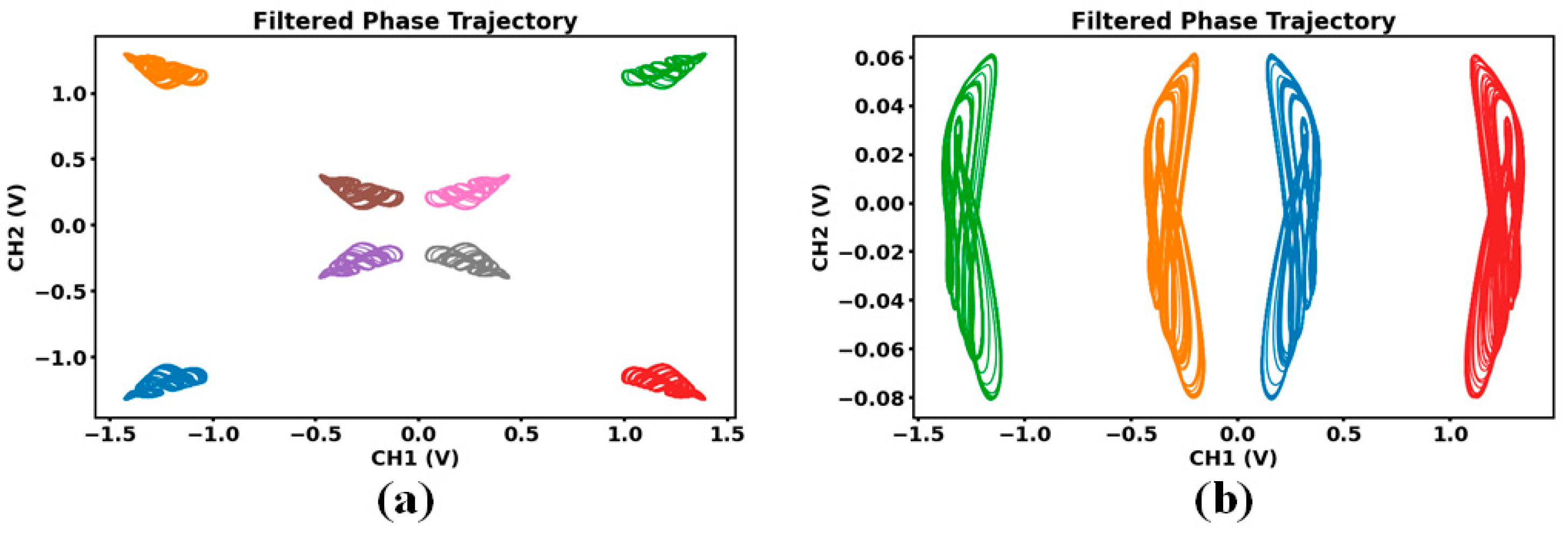
After the system architecture was constructed, parameters were configured, the offset boosting mechanism was implemented, and the distributed control strategy was established, the bitstream file was programmed onto the board to operate the chaotic system. At this stage, the system’s output signal was observed using an oscilloscope, and its phase portrait was plotted to verify the operational state of the system, as shown in Figure 18. Due to differences in sampling time and rate, the output waveform displayed on the oscilloscope exhibited certain deviations. Furthermore, noise interference could be introduced during the actual measurement process. To ensure the accuracy of the data, the chaotic waveform captured by the oscilloscope was exported and post-processed using Python (version 3.9.0). After the raw data were denoised using a low-pass filter, the actual phase portrait of the chaotic system was able to be more clearly revealed. Figure 19 shows the phase portrait of System (3) with the introduction of the tan function. Figure 20 presents the phase portrait of System (5), in which a V-shaped attractor distribution is exhibited. Figure 21 displays the phase portrait of System (7), where an X-shaped attractor distribution is formed.

5. Conclusions

The distribution control of coexisting attractors plays an important role in the application of nonlinear systems. Different patterns of distribution mean different combinations of polarities and average values of chaos. Based on a chaotic system with two-dimensional offset boosting, diverse and well-structured distributions of coexisting attractors can be obtained with the feedback of periodic and other piecewise linear functions. Focusing on different dimensions, coexisting chaotic attractors can be reproduced with the distribution of 1-shaped, tilted-1-shaped, V-shaped, and X-shaped patterns. The amplitude controller can not only modify the slope of distribution line but also resale the attractor in corresponding dimensions. Notice that the generation of coexisting attractors relies on the combination of periodic faction and other piecewise linear functions for offset regulation, such as the tangent function. However, this approach is not limited to tangent function; other periodic functions such as sine or sawtooth wave function can also be employed for similar attractor self-reproducing. Furthermore, the X-shaped pattern exhibits strong symmetry and diagonal controllability, making it suitable for chaos-based applications. The hardware implementation based on FPGA verifies the distribution of coexisting attractors.

Author Contributions

M.S.: investigation, circuit simulation, formal analysis, writing—original draft; C.L.: conceptualization, methodology, writing—review and editing, project administration; L.W.: validation, visualization, writing—review and editing; Y.X.: investigation, software, formal analysis; X.Q.: methodology, writing—review and editing. All authors have read and agreed to the published version of the manuscript.

Funding

This work was supported financially by the National Natural Science Foundation of China (Grant No.: 62371242).

Data Availability Statement

All relevant data are within the paper.

Conflicts of Interest

We declare that we have no known competing financial interests or personal relationships that could have appeared to influence the work reported in this paper.

References

  1. Tsonis, A.A. Chaos: From Theory to Applications; Springer Science & Business Media: Berlin/Heidelberg, Germany, 2012. [Google Scholar]
  2. Karimov, T.; Rybin, V.; Kolev, G.; Rodionova, E.; Butusov, D. Chaotic communication system with symmetry-based modulation. Appl. Sci. 2021, 11, 3698. [Google Scholar] [CrossRef]
  3. Baptista, M.S. Chaos for communication. Nonlinear Dyn. 2021, 105, 1821–1841. [Google Scholar] [CrossRef]
  4. Zhang, G.; Shao, S.; Huang, T. A high-data-rate hybrid index communication system based on quadrature chaos shift keying. Chaos Solitons Fractals 2024, 185, 115117. [Google Scholar] [CrossRef]
  5. Wang, X.; Chen, S.; Zhang, Y. A chaotic image encryption algorithm based on random dynamic mixing. Opt. Laser Technol. 2021, 138, 106837. [Google Scholar] [CrossRef]
  6. Alawida, M. A novel DNA tree-based chaotic image encryption algorithm. J. Inf. Secur. Appl. 2024, 83, 103791. [Google Scholar] [CrossRef]
  7. Li, L. A novel chaotic map application in image encryption algorithm. Expert Syst. Appl. 2024, 252, 124316. [Google Scholar] [CrossRef]
  8. Skinner, J.E.; Molnar, M.; Vybiral, T.; Mitra, M. Application of chaos theory to biology and medicine. Integr. Physiol. Behav. Sci. 1992, 27, 39–53. [Google Scholar] [CrossRef] [PubMed]
  9. Chirumbolo, S.; Franzini, M.; Tirelli, U.; Ricevuti, G.; Loprete, F.; Richelmi, T.; Vaiano, F.; Galoforo, A.C.; Chierchia, M.; Valdenassi, L. Harnessing Adaptive Chaos: Exploring the role of oxygen-ozone therapy in modulating complexity and repair in spine disorders via a bio-informatic model. bioRxiv 2025. [Google Scholar] [CrossRef]
  10. Deng, Q.; Wang, C.; Sun, J.; Sun, Y.; Jiang, J.; Lin, H.; Deng, Z. Nonvolatile CMOS memristor, reconfigurable array, and its application in power load forecasting. IEEE Trans. Ind. Inform. 2023, 20, 6130–6141. [Google Scholar] [CrossRef]
  11. Wang, M.; Gu, L. Multiple mixed state variable incremental integration for reconstructing extreme multistability in a novel memristive hyperchaotic jerk system with multiple cubic nonlinearity. Chin. Phys. B 2024, 33, 020504. [Google Scholar] [CrossRef]
  12. Zhu, L.; Wang, Y. Switchable memristive HR neurons with hidden firing patterns and offset boosting dynamics. Eur. Phys. J. Spec. Top. 2025, 34, 1–18. [Google Scholar] [CrossRef]
  13. Ma, C.; Mou, J.; Xiong, L.; Banerjee, S.; Liu, T.; Han, X. Dynamical analysis of a new chaotic system: Asymmetric multistability, offset boosting control and circuit realization. Nonlinear Dyn. 2021, 103, 2867–2880. [Google Scholar] [CrossRef]
  14. Xin, Z.J.; Lai, Q. Dynamical investigation and encryption application of a new multiscroll memristive chaotic system with rich offset boosting features. Chaos Solitons Fractals 2024, 181, 114696. [Google Scholar] [CrossRef]
  15. Zhang, J.; Wang, P.; Wang, X.; Cheng, N. The design, circuit realization and applications of chaotic system with offset-boosting and multistability. Phys. Scr. 2024, 99, 085206. [Google Scholar] [CrossRef]
  16. Leng, X.; Wang, X.; Zeng, Z. Memristive Hopfield neural network with multiple controllable nonlinear offset behaviors and its medical encryption application. Chaos Solitons Fractals 2024, 183, 114944. [Google Scholar] [CrossRef]
  17. Feudel, U.; Grebogi, C. Multistability and the control of complexity. Chaos Interdiscip. J. Nonlinear Sci. 1997, 7, 597–604. [Google Scholar] [CrossRef]
  18. Liu, J.; Sun, K.; Wang, H. Mechanism of multistability in chaotic maps. Chaos Interdiscip. J. Nonlinear Sci. 2024, 34, 083102. [Google Scholar] [CrossRef] [PubMed]
  19. Tang, D.; Wang, C.; Lin, H.; Yu, F. Dynamics analysis and hardware implementation of multi-scroll hyperchaotic hidden attractors based on locally active memristive Hopfield neural network. Nonlinear Dyn. 2024, 112, 1511–1527. [Google Scholar] [CrossRef]
  20. Li, C.; Sprott, J.C.; Mei, Y. An infinite 2-D lattice of strange attractors. Nonlinear Dyn. 2017, 89, 2629–2639. [Google Scholar] [CrossRef]
  21. Muthuswamy, B.; Banerjee, S. A Route to Chaos Using FPGAs; Springer: Berlin/Heidelberg, Germany, 2015. [Google Scholar]
  22. Moreira Bezerra, J.I.; Machado, G.; Iankowski Soares, R.; Valduga de Almeida Camargo, V.; Molter, A. FPGA implementation of low cost and low power chaotic encryption scheme based on a discrete-space chaotic map. Multimed. Tools Appl. 2025, 84, 33331–33352. [Google Scholar] [CrossRef]
  23. Li, C.; Gao, Y.; Lei, T.; Li, R.Y.M.; Xu, Y. Two independent offset controllers in a three-dimensional chaotic system. Int. J. Bifurc. Chaos 2024, 34, 2450008. [Google Scholar] [CrossRef]
  24. Li, C.; Shen, M.; Wang, L.; Xue, Y.; Qi, X. Diagonal attractor self-reproducing via a single periodic function. Nonlinear Dyn. 2025, 1–13. [Google Scholar] [CrossRef]
  25. Kahan, W. IEEE standard 754 for binary floating—Point arithmetic. Lect. Notes Status IEEE 1996, 754, 11. [Google Scholar]
Figure 1. Chaotic attractor of System (2) with a = 3.9, b = 3.5, c = 19, and d = 0.05, and IC = (−9, −8, 0): (a) x-y projection; (b) x-z projection.
Symmetry 17 01331 g001
Figure 2. The 1-shaped coexisting attractors of System (2) with a = 3.9, b = 3.5, c = 19, and d = 0.05. The different colors (blue, purple, pink, yellow, green) correspond to different initial conditions specified by IC = (−9 + 20, −8, 0) (−2 ≤ n ∈ Z ≤ 2): (a) x-y projection; (b) x-z projection.
Symmetry 17 01331 g002
Figure 3. Chaotic attractor of System (3) with a = 3.9, b = 3.5, and IC = (−9, −8, 0): (a) x-y projection; (b) x-z projection.
Symmetry 17 01331 g003
Figure 4. Tilted-1-shaped coexisting attractors of System (3) with a = 3.9, b = 3.5. The different colors (blue, purple, pink, yellow, green) correspond to different initial conditions specified by IC = (−9 + 10, −8 + 10, 0) (−2 ≤ n ∈ Z ≤ 2): (a) x-y projection; (b) x-z projection.
Symmetry 17 01331 g004
Figure 5. Dynamical evolution of System (3) with a = 3.9, b = 3.5, and IC = (−9 + 10, −8 + 10, 0) (−50 ≤ n ∈ Z ≤ 50): (a) rescaled average values; (b) Lyapunov exponents.
Symmetry 17 01331 g005
Figure 6. Representative solutions in Equation (3) with a = 3.9 and IC = (−9, −8, 0): (a) b = 3.0 (period 1); (b) b = 3.2 (period 2); (c) b = 4.1 (period 4); (d) b = 4.4 (chaos).
Symmetry 17 01331 g006
Figure 7. Tilted-1-shaped distributed coexisting attractors of Equation (3) with a = 3.9, b = 3.5. The different colors (blue, purple, pink, yellow, green) correspond to different initial conditions specified by IC = (−9 + 10, −8 + 10, 0) (−2 ≤ n ∈ Z ≤ 2): (a) b = 3.0, periodic. (b) b = 4.4, chaotic. Here, the type of coexisting attractors is governed by b without changing the slope of distribution.
Symmetry 17 01331 g007
Figure 8. Phase portraits and mean value plots of coexisting attractors under varying values of k, k ∈ {±2, ±1, ±0.5}, when a = 3.9, b = 3.5, Different colors correspond to different k values. IC = ((−9 + 10)/k, −8 + 10, 0) (−1 ≤ n ∈ Z ≤ 1): (a) x-y projection; (b) x-dimensional mean value.
Symmetry 17 01331 g008
Figure 9. Doubled attractors and waveforms in Equation (5) with a = 3.9, b = 3.5. For (a,b), c = 12.6 and IC = (−2, −3, 0): (a) Pseudo-double-scroll attractor, (b) x(t). For (c,d), c = 15, IC = (−2, −3, 0) is purple, IC = (2, −3, 0) is yellow: (c) coexisting attractors; (d) x(t).
Symmetry 17 01331 g009
Figure 10. Coexisting attractors of System (5) with a = 3.9, b = 3.5, c = 15, Different colors represent different initial conditions IC = (−2 − 10, −3 + 10, 0) is blue, IC = (2 + 10, −3 + 10, 0) is green (0 ≤ n ∈ Z ≤ 2): (a) x-y plane; (b) x-z plane.
Symmetry 17 01331 g010
Figure 11. Coexisting attractors of System (5) with a = 3.9, b = 3.5. Yellow corresponds to c = 40 with IC = (±27 ± 10π, −3 + 10π, 0); Purple corresponds to c = 20 with IC = (±7 ± 10π, −3 + 10π, 0); Pink corresponds to c=20 with IC = (±7, −3, 0); Orange corresponds to c = 40 with IC = (±27, −3, 0): (a) x-y plane; (b) x-z plane.
Symmetry 17 01331 g011
Figure 12. Coexisting solutions of System (5) with a = 3.9, b = 3.5: (a) bifurcation diagram. Here, IC = (−2, −3, 0) is red and IC = (2, −3, 0) is green; (b) Lyapunov exponents.
Symmetry 17 01331 g012
Figure 13. Mechanism for the attractor distribution of V-shaped coexisting attractors.
Symmetry 17 01331 g013
Figure 14. Pseudo-multi-scroll attractor of System (10) with a = 3.9, b = 3.5, c = 12.6, d = 9.95, and IC = (−2, −3, 0): (a) pseudo-four-scroll attractor; (b) y(t), c = 12.6, d = 15, IC = (−2, −3, 0) is purple, IC = (−2, 3, 0) is yellow; (c) pseudo-two-scroll attractor; (d) y(t), c = 15, d = 9.95, IC = (−2, −3, 0) is purple, IC = (2, −3, 0) is yellow; (e) pseudo-two-scroll attractor; (f) x(t).
Symmetry 17 01331 g014
Figure 15. Coexisting attractors of System (7) with a = 3.9, b = 3.5, d = 15. The initial condition IC = (−2 − 10, −3 − 10, 0) is magenta, IC = (2 + 10, −3 − 10, 0) is green, IC = (−2 − 10, 3 + 10, 0) is blue, and IC = (2 + 10, 3 + 10, 0) is amber, where 0 ≤ n ∈ Z ≤ 2: (a) x-y plane; (b) y-z plane.
Symmetry 17 01331 g015
Figure 16. Coexisting attractors of System (8) with a = 3.9, b = 3.5, d = 15, where a new parameter k is introduced to rescale the system variable x: (a) when k = 0.5, the attractors are symmetrically distributed along the directions of y = ±0.5x; (b) when k = 2, the attractors are symmetrically distributed along the directions of y = ±2x. IC = (−2 − 10, −3 − 10, 0) is purple, IC = (2 + 10, −3 − 10, 0) is green, IC = (−2 − 10, 3 + 10, 0) is blue, and IC = (2 + 10, 3 + 10, 0) is orange (where 0 ≤ n ∈ Z ≤ 2).
Symmetry 17 01331 g016
Figure 17. RTL diagram of the chaotic system implemented on FPGA.
Symmetry 17 01331 g017
Figure 18. Photograph of the oscilloscope and FPGA hardware setup.
Symmetry 17 01331 g018
Figure 19. Three typical coexisting chaotic attractors of System (3) generated by the FPGA output. The different colors (blue, orange, green) correspond to different initial conditions specified by IC = (−9 + 10, −8 + 10, 0) (−1 ≤ n ∈ Z ≤ 1): (a) xy plane; (b) yz plane.
Symmetry 17 01331 g019
Figure 20. Four typical coexisting chaotic attractors of System (5) generated in the platform of FPGA output. IC = (−2 − 10π, −3 − 10π, 0) is blue, IC = (2 + 10π, −3 − 10π, 0) is red, IC = (−2, −3,0) is orange, and IC = (2, −3, 0) is green: (a) xy plane; (b) xz plane.
Symmetry 17 01331 g020
Figure 21. Eight typical coexisting chaotic attractors of System (7) generated by the FPGA output: (a) xy plane, IC = (−2 − 10π, −3 − 10π, 0) is blue, IC = (2 + 10π, −3 − 10π, 0) is red, IC = (−2 − 10π, 3 + 10π, 0) is orange, and IC = (2 + 10π, 3 + 10π, 0) is green, IC = (−2, −3, 0) is purple, IC = (2, −3, 0) is gray, IC = (−2, 3, 0) is brown, and IC = (2, 3, 0) is pink; (b) yz plane, IC = (2, ±3, 0) is blue, IC = (2 + 10π, ±3 ± 10π, 0) is red, IC = (−2, ±3, 0) is orange, and IC = (−2, ±3 ± 10π, 0) is green.
Symmetry 17 01331 g021
Table 1. The cost of nonlinear feedback for different distributions.
Distribution Type1-Shaped
Distribution
Tilted-1-Shaped DistributionV-Shaped
Distribution
X-Shaped
Distribution
Trigonometric function1111
Absolute value function0013
Signum
function
0012
Number of
offset operations
0011
Table 2. Initial parameter settings in the CONTROL module of System (3).
xyz
xs13F8000003F8000003F800000
xs2BB7F9724BB656041BA83126E
xs303DCCCCCC0
cs1xyz
cs23F8000003F8000003F800000
cs33F800000z3F800000
cs4zzy
cs5000
cs60y0
cs73F8000000x
cs8000
cs9000
Disclaimer/Publisher’s Note: The statements, opinions and data contained in all publications are solely those of the individual author(s) and contributor(s) and not of MDPI and/or the editor(s). MDPI and/or the editor(s) disclaim responsibility for any injury to people or property resulting from any ideas, methods, instructions or products referred to in the content.