Review

A Review of Vector Field-Based Tool Path Planning for CNC Machining of Complex Surfaces

College of Mechanical and Vehicle Engineering, Changsha University of Science and Technology, Changsha 410114, China
*
Author to whom correspondence should be addressed.
Symmetry 2025, 17(8), 1300; https://doi.org/10.3390/sym17081300
Submission received: 23 June 2025 / Revised: 22 July 2025 / Accepted: 4 August 2025 / Published: 12 August 2025
(This article belongs to the Section Engineering and Materials)

Abstract

With the development of modern manufacturing industry, complex surface parts are more and more widely used in aerospace, automobile manufacturing, the shipbuilding industry, and many other fields; furthermore, their machining demand is growing explosively, and CNC machining technology has become the mainstream machining method of complex surface parts because of its high precision and high efficiency. However, CNC machining of complex surfaces faces many challenges, especially the generation and optimization of tool trajectories. Therefore, vector field-based tool path planning methods have emerged, aiming to improve the efficiency and accuracy of CNC machining of complex surfaces. This paper focuses on the tool trajectory optimization problem in CNC machining of complex surfaces and reviews the current research status of vector field-based tool path planning for surface machining. The study explores the concept of symmetry in the design of tool paths, highlighting the importance of symmetrical vector fields in achieving efficient and high-precision machining. By analyzing the symmetrical properties of complex surfaces and the corresponding vector fields, this paper discusses the current status, difficulties, and core problems of relevant methods, pointing out the direction of breakthroughs and the future development trend. The findings provide a reference and basis for the realization of efficient and high-precision CNC machining of complex surfaces.

1. Introduction

Complex surface parts are widely used in aviation, aerospace, automobile, ship, mold, and other high-precision fields, such as aviation engine blades, automobile body molds, and ship propellers [1]. Their design and manufacturing accuracy are related to product performance, reliability, and market competitiveness. CNC machining technology has become the first choice for complex surface machining due to its high precision, high efficiency, and highly automated machining mode [2,3]. CNC machining of surfaces is directly driven by the machining paths on the surface [4], therefore, designing efficient machining paths is the key to improving machining efficiency and ensuring the accuracy of surface molding of parts [5]. Complex surface machining requires efficient tool path planning to balance geometric accuracy and kinematic performance. Traditional methods often ignore surface symmetry, leading to uneven tool paths and increased machining errors. Vector field-based approaches address this by integrating symmetry analysis as follows: for instance, symmetric vector fields can align tool trajectories with surface principal axes, reducing tool wear and improving feed smoothness. The symmetry of tool axis vectors (e.g., uniform angular distribution) also enhances machine tool motion stability, as seen in five-axis machining, where symmetric attitude changes minimize rotational axis acceleration fluctuations.
Therefore, the vector field-based tool path planning method has emerged, the core of which lies in the use of vector fields to accurately describe the geometric and physical characteristics of complex surfaces, and to guide the generation and optimization of tool trajectories through the construction of a reasonable vector field model to improve the efficiency and accuracy of CNC machining of complex surfaces in an all-round way. In CNC machining, the optimization of tool trajectory based on vector field can make the tool more coordinated and smoother in the machining process. Additionally, it can significantly improve the machining efficiency [6]. At the same time, it can also suppress load fluctuation, reduce tool vibration and wear, and reduce machining costs. Therefore, tool trajectory optimization based on vector field is an important research direction in CNC machining. The vector field schematic is shown in Figure 1.
In the context of vector field-based tool path planning, the research can be subdivided into two main branches [7]. On the one hand, research focuses on the optimization of tool attitude, especially on the smoothness of the tool axis vectors [8,9,10], aiming to improve the smoothness and efficiency of the machining process by optimizing the attitude distribution of the tool in space. On the other hand, researchers have focused on tool position optimization [11,12,13,14]. This direction is directly aimed at the fine control of the specific position and travel direction of the tool on the machining path, aiming at the efficient and precise planning of the tool trajectory through the guidance and constraints of the vector field, so as to further improve the machining quality and productivity.
In the in-depth vector field-based milling of complex surfaces, tool path planning needs to build a dynamic balance between geometric constraints, kinematic limitations, and process parameters, and achieve optimization goals such as maximizing cutting bandwidth, minimizing energy loss, optimizing material removal rate, controlling motion smoothness, and subdividing the machining area through vector fields. Although these optimization objectives show great potential in improving the efficiency and quality of CNC machining of complex surfaces, they also face their own challenges and limitations [15]. Therefore, the purpose of this paper is to discuss the tool path planning in complex surface CNC machining, and the application prospects of vector field research in surface machining, as well as to discuss in detail the current status of research on related technologies and point out the direction of breakthroughs and the future development trend, in order to realize the machining process of the “perception-decision-execution” of the whole closed-loop optimization, and the complex surface of the surface. Furthermore, it provides a reference and basis for the realization of “perception-decision-execution” closed-loop optimization of the machining process and efficient high-precision machining of complex surfaces.

2. Conventional Tool Path Planning Methods for Complex Surfaces

In the field of complex surface CNC machining, the planning of tool trajectory occupies a pivotal position, which is directly related to the quality of the workpiece, machining accuracy, and overall efficiency, and is an indispensable key pre-step in the CNC programming process. Specifically, tool path planning is based on the surface geometry of the workpiece to be machined, in which the algorithm design is used to generate a series of tool paths along the surface of the workpiece’s continuous movement. The core objective of this process is to ensure that the machining accuracy meets the preset standards, while maintaining the smoothness of the surface of the workpiece on the basis of smoothness, to achieve continuous tool trajectory without interruption, and to strive to minimize the total length of the trajectory, in order to improve machining efficiency and reduce costs. So far, many tool trajectory generation methods have been widely proposed and successfully applied in real manufacturing [16]. These methods have been summarized in detail in the literature [17], mainly including the isoparametric line method, the truncated plane line method, the CC path cross-section method, the CL path cross-section method (also known as the bias plane method), the guiding plane method (APT), the iso-illumination line method, the projection method, the mapping method, the feature extraction method, the space-filling curve method, and the method of equal residue height, etc. In view of the limitation of space and the focus of this paper, it is important to consider how to minimize the total length of tool trajectory, so as to improve machining efficiency and reduce machining cost. In view of the space limitation and the research focus of this paper, several representative methods will be introduced and analyzed, aiming to explore their principles, applicable scenarios, advantages, and disadvantages.
(1)
The isoparametric line method, first proposed by Loney et al. [18], is widely used in multi-coordinate machining due to its simplicity, as it generates paths along surface parametric lines [19]. However, its critical limitation lies in the non-linear mapping between parameter space and Euclidean space, leading to uneven path spacing and potential undercutting; this makes it unsuitable for highly curved surfaces. He et al. [20] addressed this by developing an adaptive mesh optimization method, which reduces transformation deviation but increases computational complexity, highlighting a trade-off between accuracy and efficiency that subsequent methods (e.g., the truncated plane method) sought to resolve.
(2)
The intercept plane method generates paths via intersections between parallel planes and the machined surface [21], showing strong applicability to sheared parametric surfaces. However, its reliance on solving nonlinear equations leads to high computational costs, and conservative line spacing (to ensure accuracy) reduces efficiency; this contrasts the isoparametric line method, which is simpler but less adaptable, revealing a fundamental tension between universality and computational feasibility in traditional path planning.
(3)
The equal illuminance line method was first proposed in 1984. There are many points on a surface with the same illuminance, and the curve formed by connecting these points is called the line of equal illuminance. Since the illuminance side reflects the smoothness of a surface, the method was initially used to check the continuity of surfaces. Later, Han et al. [22] proposed the following innovative idea: the complex surface of a workpiece surface is approximated as consisting of multiple piecewise straight curves. Under this assumption, we further connect points with the same illumination level to each other to form a series of boundary curves or localization buses located on the surface. More accurate positioning is achieved, so the method is also used in five-axis CNC machining with more and more accurate positioning coordinates.
(4)
The basic idea of the mapping method is to first map the three-dimensional surface to be machined into a two-dimensional plane, then calculate the tool trajectory for the two-dimensional plane. Following this, the tool position points of the obtained two-dimensional plane are corresponded to the three-dimensional surface one by one through the mapping to obtain the tool trajectory [23]. Han et al. [24] applied this method to complex impeller surfaces by mapping the trajectories from the parametric domain to the physical domain to obtain the tool path. For the mapping method, the direction of 3D parametric mapping directly affects the geometric fidelity and kinematic characteristics of the tool trajectory, which in turn determines the machining efficiency and molding accuracy of the method. Therefore, this method is widely used in tool path planning for curved cavity-like structures and multi-feature combination surfaces.
(5)
The equal residual height method is designed to improve machining efficiency, reduce machining time, and ensure machining accuracy by maintaining the machining residual height between adjacent tool paths within a preset maximum allowable value [25]. This method was first proposed by Suresh et al. [26] and is currently the most widely used method.
In the equal residual height machining method for parametric surfaces, the first trajectory is generally based on a boundary line of the parametric surface. The next tool trajectory is calculated based on the first trajectory line and the equal residual height, and so on, until the whole surface is covered, so the residual heights of the neighboring tool trajectories are kept the same [27]. In the subsequent research, many experts and scholars have improved and expanded the equal residual height method. Hauth et al. [28] combined the advantages of various methods and skillfully combined the equal residual height method with the CC space method, which significantly improved the accuracy of tool position location on parametric surfaces. Hao et al. [29] analyzed the compatibility of different types of tools with the equal residual height method, especially the calculation of the step length and row spacing of annular tools in the machining process, which provides strong support for optimizing the machining time of parametric surfaces. Zhao et al. [30], on the basis of reviewing the equal residual height method, pointed out that the traditional equal residual height method leads to trajectory distortion due to the influence of curvature change, and proposed an improved equal residual algorithm, which was successfully applied to machining of complex parametric surfaces to realize the efficient generation of tool trajectories. At the same time, Ye et al. [31] innovatively proposed the strategy of matching the curvature change of the workpiece parametric surface morphology and tool position points in all directions from the perspective of improving the overall machining efficiency, based on which a more reasonable tool trajectory is planned, which opens up a new way to improve the machining efficiency. Although the calculation volume of the equal residual height method is relatively large, which may lead to lower efficiency in the early stage, its unique advantage is that it can guarantee the machining efficiency and machining accuracy at the same time. With the rapid development of today’s computer science, powerful computational capabilities have greatly alleviated the challenges posed by large-scale computation. Therefore, the application of the requires dual height method to parametric surfaces has become increasingly widespread [32,33,34,35].
Two main planning strategies exist for mesh surface models. One strategy is to first perform a bias process on the triangular mesh model to generate an isometric bias model. The biasing process involves offsetting each vertex or face of the original mesh by a constant distance along the normal direction of the mesh surface. Subsequently, on the basis of the isometric bias model, the tool feed positions, i.e., tool points, are accurately calculated. These points need to be carefully planned to ensure that the residual height of the machined surface meets the design requirements. Eventually, these points are connected in an orderly manner and finally planned as tool trajectories [36,37]. Another strategy is to compute tool contacts directly on the original triangular mesh model. Subsequently, these tool contacts are biased to obtain the corresponding tool position points. This approach avoids the step of generating an isometric bias model and operates directly on the original mesh, which improves computational efficiency. Generating tool trajectories with equal residual heights on mesh surface models has been a hot and difficult issue for many scholars. Tournier [33] proposed a bias-based method for equal residual height tool trajectories on triangular mesh surface models. He firstly performs equidistant bias based on the mesh model with the value of the maximal residual height and the value of the tool radius, to obtain the residual surface and the tool position surface, respectively, and then the equal residual height tool trajectory is calculated on these two surfaces. Chen [38] proposes an equal residual trajectory method for triangular mesh surface models to estimate curvature. Instead of offsetting the mesh, the method estimates the curvature directly by numerical computation and determines the machining row spacing based on the maximum residual height. Subsequently, the tool contact points are derived, the machining trajectory is obtained after biasing, and the interference elimination process is performed.
In CNC machining of complex surfaces, current research on tool path planning remains largely confined to the static geometry of conventional machining. It focuses only on whether the tool path is geometrically feasible for machining. It does not consider the impact of machine tool processing capabilities, tool cutting directions, or dynamic cutting characteristics during machining. These factors affect the forming accuracy, machining efficiency, and surface physical properties of complex curved parts. Additionally, existing research lacks specialized and in-depth analysis of vector field-based methods. Therefore, for existing high-speed milling CNC machining, a new research focus has emerged. It involves introducing the vector field concept into tool path planning for complex surfaces. This approach carefully considers surface geometric and physical properties. It also takes into account tool motion and the dynamic characteristics of the cutting process. This has become a research hotspot in the field and represents a future development trend [36,37].

3. Vector Field-Based Tool Path Planning Methods for Complex Surfaces

For vector field-based CNC machining tool paths, current research focuses on the following two aspects: (1) vector field-based tool attitude optimization and (2) vector field-based tool position optimization.

3.1. Vector Field-Based Tool Attitude Optimization

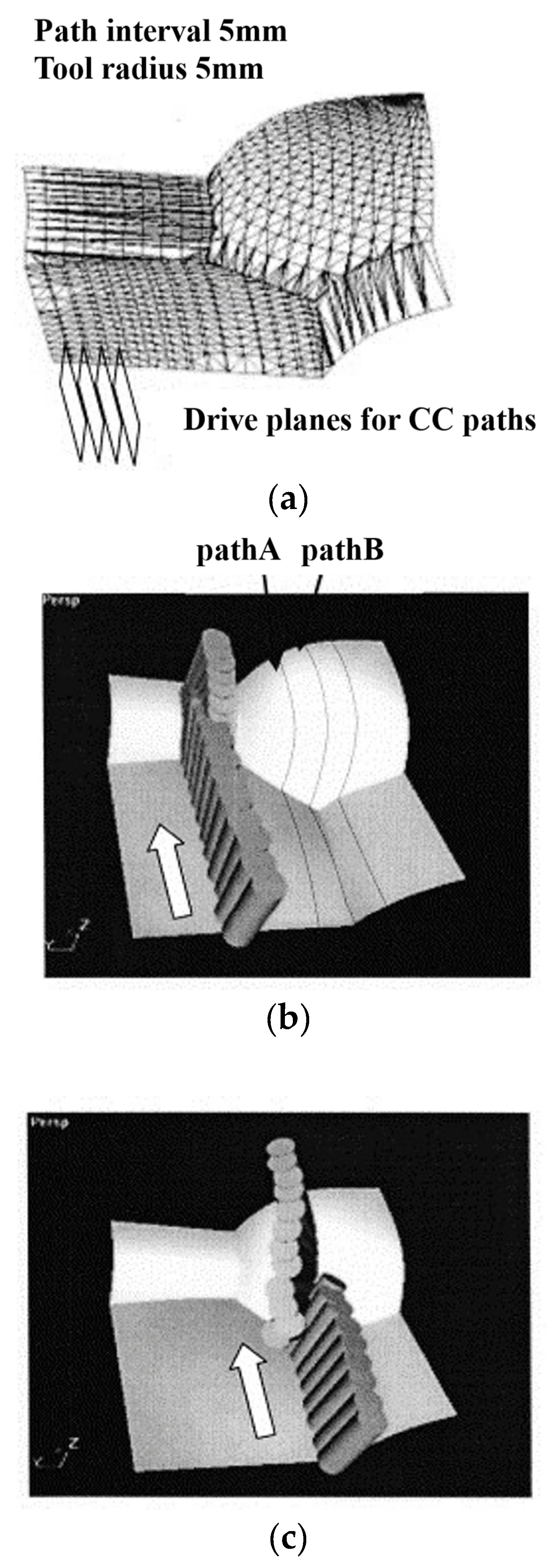
Vector field-based tool attitude optimization mainly refers to the optimization of the smoothness of the tool axis vector based on the vector field. The smoothness of tool attitude is closely related to the kinematic performance of machine tools. Early research on tool attitude optimization focused on the workpiece coordinate system, which is as follows: Jun et al. [39] generated smooth tool–axis vectors by minimizing angle changes within feasible domains, laying a foundation for geometric-based optimization. The path with the smallest sum of changes in the tool–axis vector angles was used to generate the smooth tool–axis vector field, as shown in Figure 2.
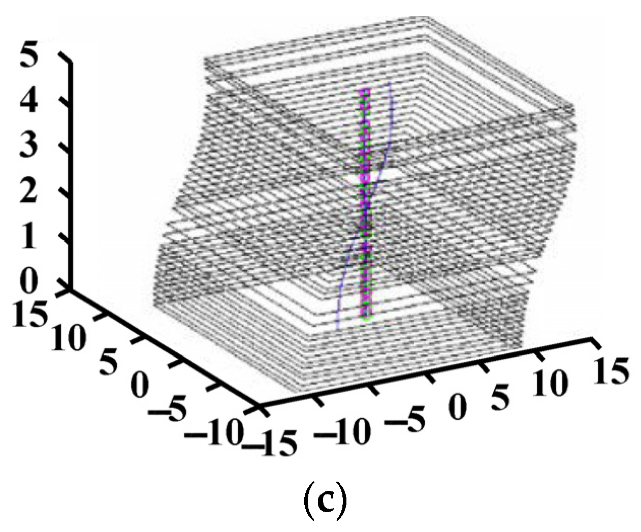
Lauwers [40] proposed a method to generate smooth tool–axis vectors by controlling the tool oscillation angle on a unit path. The developed multi-axis tool path generation algorithm can be applied to machining several part surfaces in a single operation. This feature, combined with the algorithm’s ability to adjust tool orientation—both to maximize material removal and avoid collisions between moving machine components—constitutes the innovative aspects of the presented research. Ho [41] proposed a tool–axis vector smoothing method based on spherical linear interpolation, which meets both the machining accuracy requirements and the kinematic performance of the machine tool. Wang et al. [42] proposed a method for smoothing the tool axis vector field that considers the angular velocity of tool swing and machining interference, while taking into account the constraints of tool swing between neighboring tool contacts. The presented algorithm automatically generated a five-axis tool path that is both interference-free and ensures angular velocity compliance. Through delicate computation and manipulation of visibility maps and their derivative data, the algorithm achieved computational feasibility, with acceptable computing time and memory requirements. Test examples demonstrate the promising application of this solution. Sun et al. [43] further integrate the constraints of angular velocity, angular acceleration, and angular acceleration of tool oscillation into the smoothing process of the tool axis vector field, and innovatively propose a double spline interpolation method along the contour of the predetermined feed rate, which is used to optimize the smoothing of the tool axis vector field. However, the above tool axis vector smoothness optimization methods all focus on the workpiece coordinate system. They do not consider the kinematic performance of the machine tool’s rotary axis. This can easily cause the machine tool to accelerate and decelerate frequently. It also leads to large tracking errors in the servo system. These issues, in turn, will damage the machined surface. Therefore, the optimization of tool axis vector smoothness has begun to change from the optimization in the workpiece coordinate system to the optimization in the machine tool coordinate system. Symmetric tool axis vector fields (e.g., mirror-symmetric distributions along surface ridges) minimize abrupt attitude changes, as demonstrated by Castagnetti et al. [44], who used symmetric feasible domains in machine coordinates to generate smooth trajectories. The tool path generated based on this optimized tool axis vector field is shown in Figure 3. Vector field-based tool path optimization fundamentally breaks through the limitations of geometric paths by transforming path planning into an optimal control problem of physical fields. Rather than simply changing the laser’s movement trajectory [45,46,47], the path actively adapts to the transient physical state of the material. This intelligent avoidance mechanism based on physical fields offers unparalleled advantages, especially for difficult-to-process ceramic materials containing defects (air threads/impurities).

3.2. Vector Field-Based Tool Position Optimization

Vector field-based tool position optimization refers to the optimization of the tool trajectory itself based on the vector field. In order to integrate the geometric and physical information in CNC machining, researchers determine the direction of the vector field perform relevant calculations [48], and finally plan the tool path. Regarding the optimization of tool position based on vector field, the main optimization objectives are as follows.
(1)
Maximum machining bandwidth [49]. In tool path planning, it is determined that the tool can move with the maximum machining bandwidth by considering the vectorial characteristics of the tool path (e.g, direction, speed, etc.) and the geometry of the machining area. However, it has high computational complexity and high equipment requirements, and it is more dependent on machining experience.
(2)
Optimized kinematic performance [50]. In the field of CNC machining, the kinematic characteristics of each feed axis of the machine tool are optimized by optimizing the direction and variation of the tool path and the tool axis vector field, thus ensuring speed smoothing, machining stability, and load balancing of the machine tool during the machining process.
(3)
Minimum energy consumption [51]. Under the premise of meeting the requirements of the machining task, the reasonable adjustment of the tool axis vector field to optimize the trajectory of the tool, so that the tool in the execution of the machining task requires a minimum of energy, thus reducing the production cost.
(4)
Maximum material removal rate [52]. This refers to the planning of the tool’s trajectory to achieve the optimization of the tool’s path, speed, acceleration, and other parameters through the planning of the tool axis vector field, so as to maximize the volume of material removed from the machined part per unit of time.
(5)
Optimal smoothness [53]. When performing CNC machining, the vector field is used to optimize the feed direction of the tool so that the machined surface achieves the optimum smoothness. This method not only reduces the roughness of the machined surface and improves the machining quality, but also reduces the tool wear and lowers the machining cost.
(6)
Area subdivision [54]. Area subdivision machining usually refers to the CNC machining of complex geometries. Based on the vector field, the entire machining area is subdivided into multiple sub-areas, and different machining strategies and parameter settings are formulated for the characteristics and needs of each sub-area to optimize the machining process and improve the quality of the product. In conclusion, area subdivision machining is an effective machining optimization method, which can improve production efficiency, reduce cost, improve product quality, adapt to market demand, and improve production safety.
In addition to the above common optimization objectives, there is also the fastest feed rate [55], the minimum cutting force, and the minimum deformation, etc. [56,57,58].

3.2.1. Tool Position Optimization Based on Maximum Machining Bandwidth

In order to integrate the geophysical information in CNC machining, the model surface is first sampled uniformly, and then the optimal tool travel direction is determined at each sampling point, i.e., the direction of the maximum machining bandwidth. The optimal tool travel direction at each sampling point constitutes the optimal tool travel vector field for the unified description of the geophysical information in CNC machining. Figure 4 [49] shows the maximum machining bandwidth vector field in the parameter domain.
For some bulky or structurally complex parts machining tasks, the machining bandwidth often becomes one of the key factors restricting the machining efficiency. For this reason, Fard et al. [59] used symmetric feed direction fields to maximize material removal rate in five-axis milling. They studied a maximum machining bandwidth tool path generation method for five-axis flat-end milling, the core of which lies in the fact that, by using the swept path of the flat-end milling cutter the machining process, combined with the vector field theory, the tool attitude and the depth of cut at each cutting point are accurately calculated, so as to determine the maximum machining bandwidth of degrees. Chu et al. [15] introduced the concept of field and proposed a five-axis CNC machining tool trajectory optimization method based on vector field clustering, aiming to ensure the optimal tool travel direction while ensuring the maximum machining bandwidth. In terms of feed and tool orientation, Fard et al. [60] analyze the key vectors, such as the direction of the tool motion, the direction of the cutting force, and the direction normal to the surface of the workpiece in detail to accurately determine the optimal feed direction and orientation of the tool at the point of contact and thus determine the tool trajectory with the maximum machining bandwidth. Liu et al. [61] introduce the tensor field and the partitioning strategy, which realize a comprehensive evaluation of the machining bandwidth and the tool trajectory. Liu et al. achieve a comprehensive evaluation of the machining bandwidth and optimization of the tool trajectory by introducing a tensor field and partitioning strategy to improve the efficiency of free-form surface machining. Wang et al. [62] propose a new global space method, which generates the tool trajectory with maximum machining bandwidth and optimizes the tool orientation and feed direction in parameter domains through vector field analysis and flow function calculation, focusing on the improvement of the efficiency of the backface milling, but without considering the practical constraints of the machine tool, such as the machine kinematics. Therefore, Qian et al. [63] considered the motion performance of the machine tool, optimized the feed rate of the machine under the premise that the rotary axis of the machine tool meets the motion performance of each axis, further optimized the tool axis vector field for machining of titanium alloy skins, and then obtained the maximum efficiency machining bandwidth tool paths in the mirror milling process through the discrete fitting of the numerical model, as shown in Figure 5.

3.2.2. Tool Position Optimization Based on Best Kinematic Performance

In the field of CNC machining, the tool trajectory is visualized as a complex vector field, where each point in the field accurately maps the immediate position of a tool and its velocity vector. Tool path planning based on this vector field is essentially an in-depth analytical process aimed at mining and determining the most optimal tool motion path and velocity configurations by carefully examining the properties of this vector field.
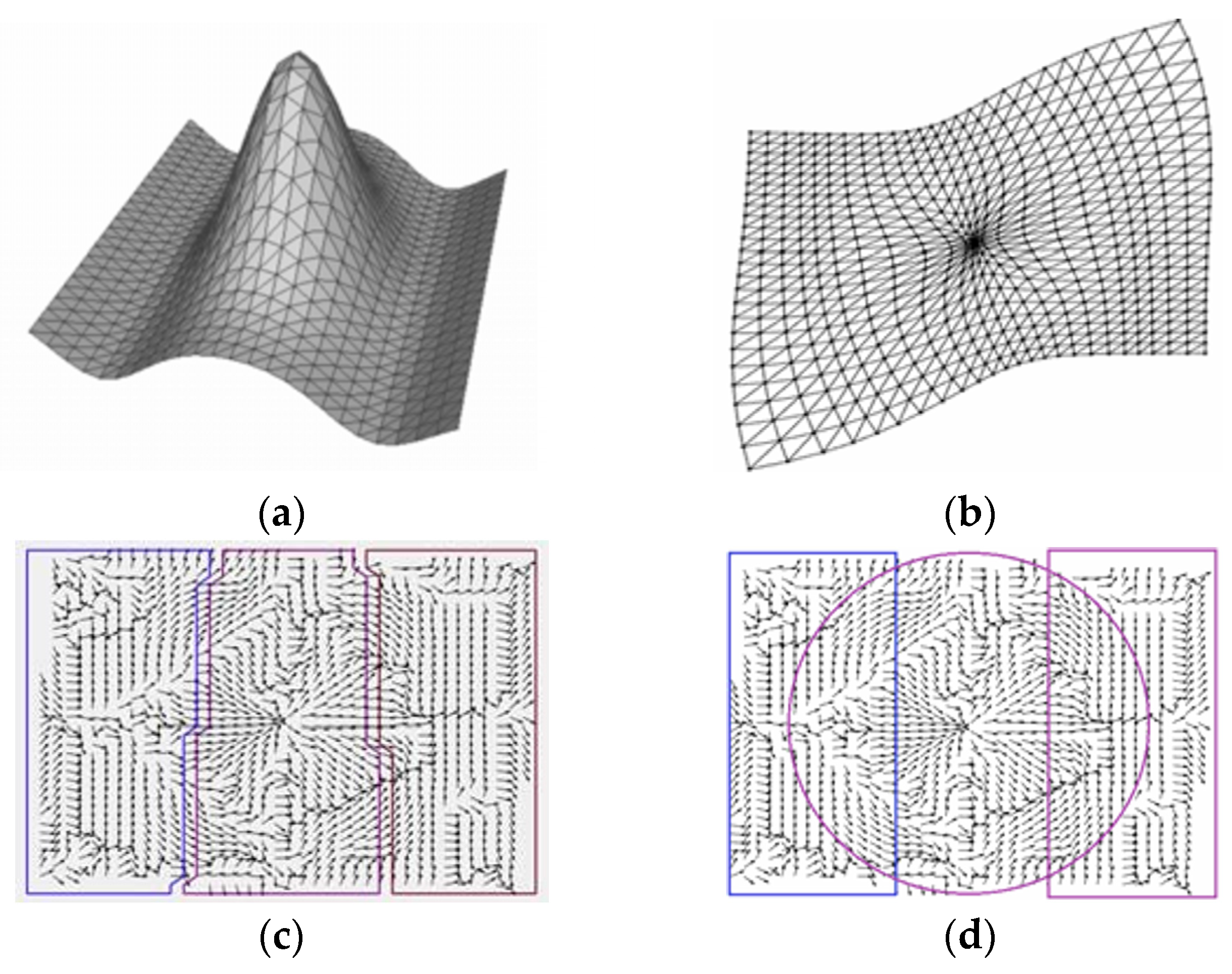
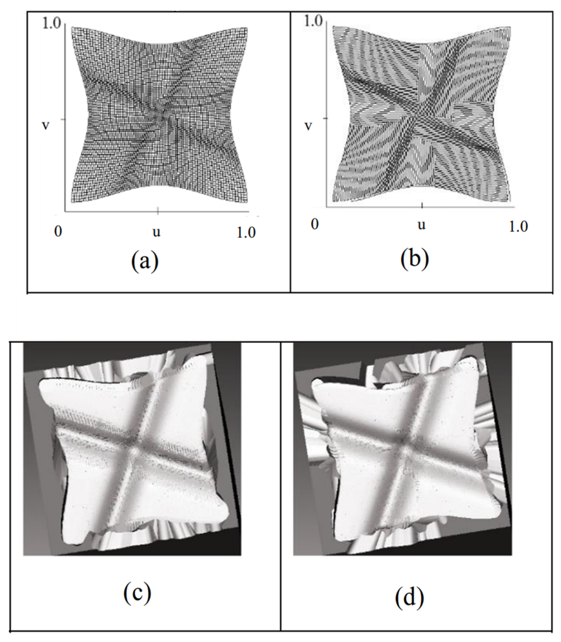
To address the kinematic performance optimization problem, researchers have proposed the following innovative approaches, from different perspectives: Dang et al. [64] proposed a five-axis machining optimization strategy from the perspective of spatial coordinate transformation, whose core idea is to transform the coordinates of the points to be milled from the workpiece coordinate system to the machine coordinate system, and to generate curved tool paths by establishing the optimal performance vector field of direction to optimize kinematic performance, as shown in Figure 6. Kim et al. [50] proposed a heuristic-based greedy algorithm from the dimension of time optimization. This method considers multiple constraints, such as the kinematic performance of the machine tool, the motor speed limit, and the surface finish requirement, and improves the overall machining performance and guarantees the machining quality by searching for the optimal performance direction.

3.2.3. Tool Position Optimization Based on Minimum Energy Consumption

In the whole machining process, introducing the vector field theory to optimize the tool path, cutting parameters, and motion trajectory, providing a new and effective way to reduce the energy consumption of machine tools and tools [65]. Compared to the traditional tool path, the depth of cut, feed rate, and spindle speed are basically the same. In order to minimize energy consumption, Xu et al. [51] investigated the basic problem of how to plan a five-axis tool path to machine the surface of an arbitrary freeform part on a given type of machine tool. The method establishes an algebraic model on the part surface of the vector field of the energy flow density, generates the tool trajectory based on the vector field, as shown in Figure 7, and compares the experimental results to some popular optimization methods for the tool trajectory, (e.g., Equal Residual Height Method), ensuring the energy consumption is minimized. Pavanaskar et al. [66] proposed a method for generating a smooth tool axis vector field (TAVF) and optimizing tool paths in five-axis machining, which optimizes the tool axis vector field and tool paths in five-axis machining through a mathematical framework and numerical calculations aiming to minimize the machining energy consumption.

3.2.4. Tool Position Optimization Based on Maximum Material Removal

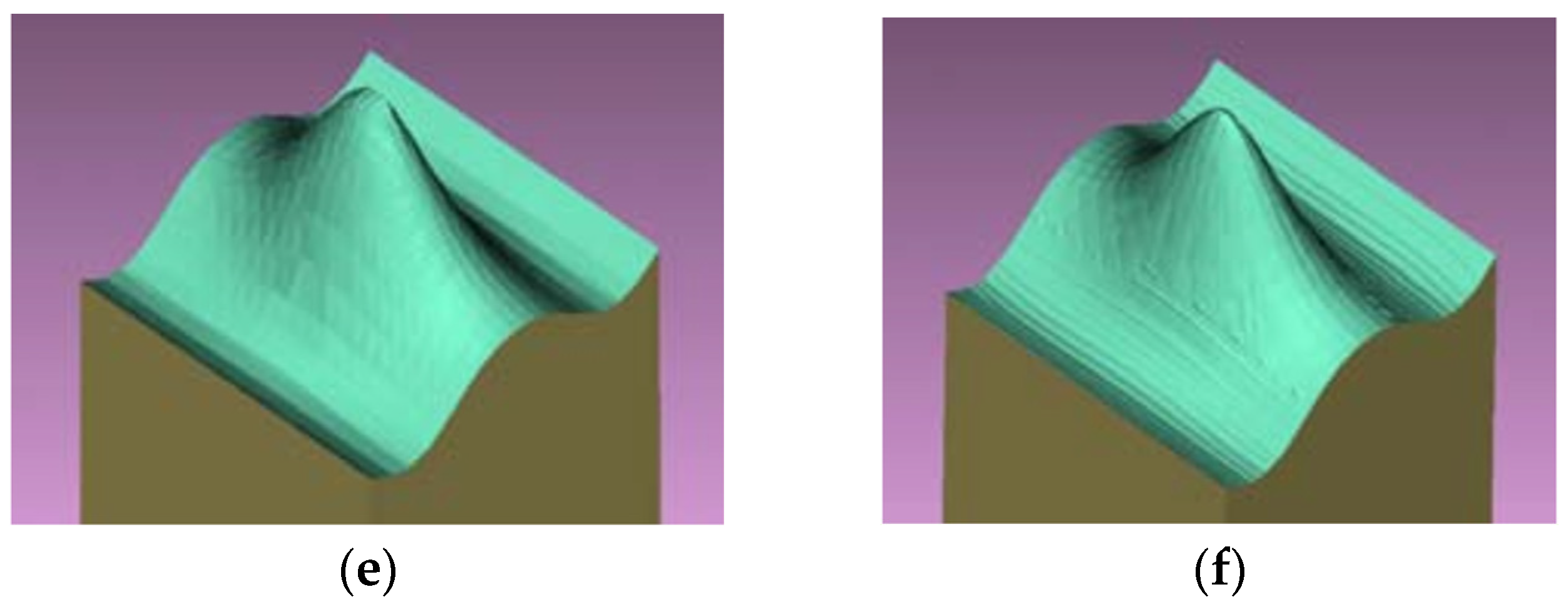
This method introduces the concept of a vector field in order to achieve the tool path planning with a maximum material removal rate. Hu et al. [67] proposed a new tool path generation method for five-axis machining, which ensures the maximization of the material removal rate during machining by establishing a vector field model that characterizes the material removal rate and the feed direction, and by determining the optimal feed direction at each cutting point by using the contour expansion method. Makhanov [68] proposed a new algorithm to improve the productivity of a five-axis milling machine by improving the coordinates of the points to be milled by converting the coordinate system from the workpiece coordinate system to the machine coordinate system to maximize the material removal rate during machining, as shown in Figure 8. The algorithm optimizes the cutting path to maximize the material removal rate while ensuring the best vector field orientation. Similarly, Wang et al. [69] also proposed a new method to compute the optimal feed direction vector field with a maximum material removal rate and generate efficient CNC tool paths using the equivalence method, which can help to improve machining efficiency, reduce cost, and achieve high-quality machining.

3.2.5. Smoothness-Based Optimal Tool Position Optimization

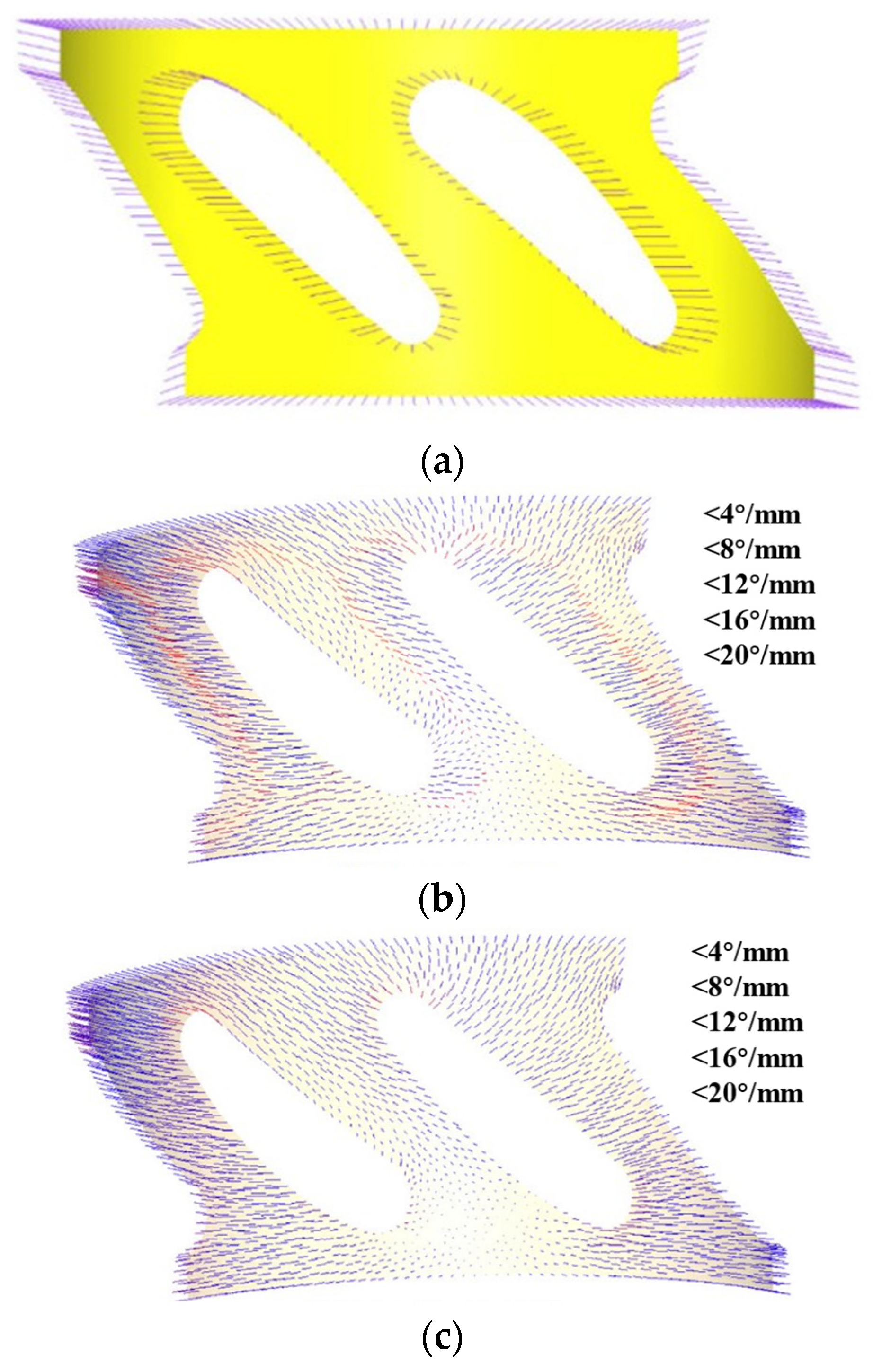
In the actual machining process, we need to analyze the tool feed direction in the vector field to find the tool trajectory that ensures the best smoothness. Huang et al. [53] incorporate the trajectory smoothness, preset tool axis alignment, and other factors into the computation of the curved tool vector field, and then propose a five-axis tool path generation algorithm based on the vector field, which generates tool paths that are smooth in the feed and traverse directions (Figure 9).
Regarding the vector field, the same Chiou et al. article [70] also constructed a machining potential field with the objective of smoothing and bandwidth direction, incorporated the part and tool geometry information to characterize the machining-oriented part surface information, carried out the machining planning, and generated a multi-axis engraving tool path based on the machining potential field (MPF) to achieve the optimal smoothness of the tool trajectory. Sun et al. [71] introduced G1-continuous vector fields with symmetric boundary conditions, ensuring seamless tool path transitions across composite surfaces. They utilized the coplanar feed vector field, smoothed the tool trajectory, and obtained the G1 continuity of the tool path, thus realizing the smooth machining of composite surfaces and greatly reducing the machining time.
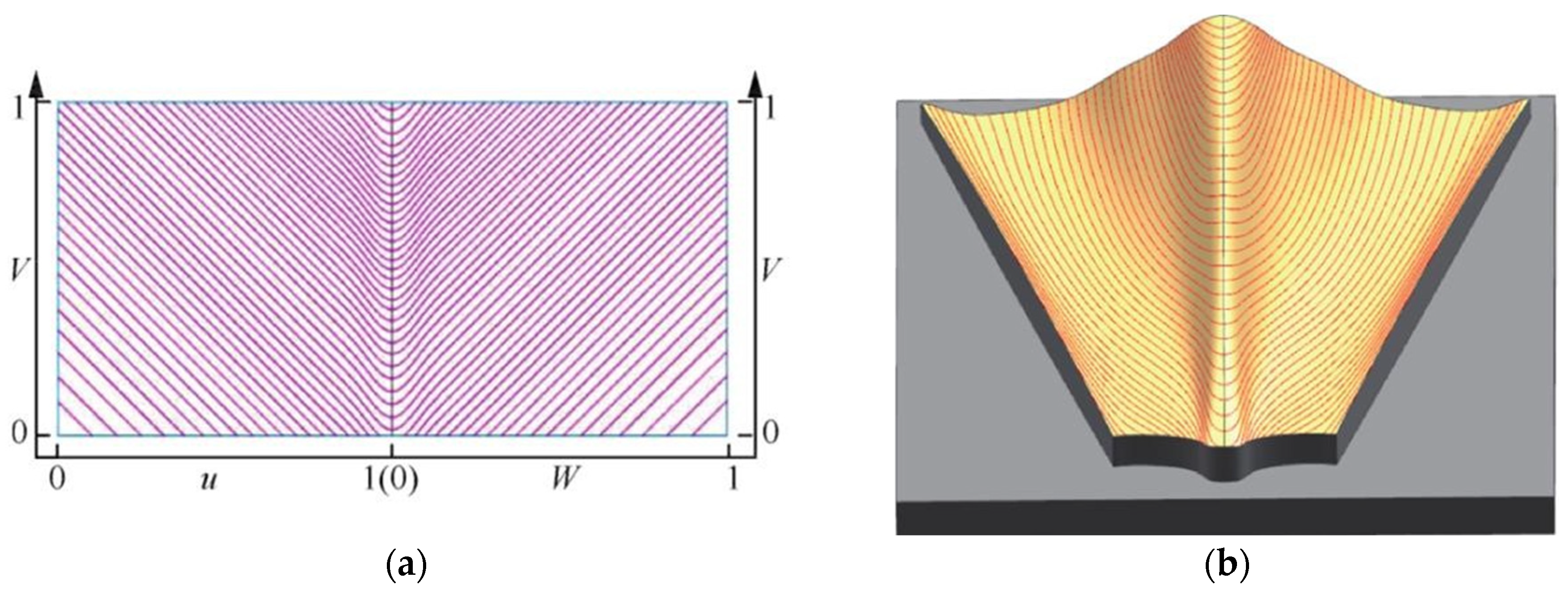
In order to solve the problem of tool feed direction deviation, Sun et al. [72] regarded the optimal feed vector field in the parameter domain as a sinusoidal flow streamline field, as shown in Figure 10 [73]. Xu generates streamlined tool trajectories from the streamline field G1 obtained according to Sun’s research method by successive smooth splicing on the composite surface.

3.2.6. Tool Position Optimization Based on Area Segmentation

In the field of CNC machining, region subdivision of complex surfaces using vector fields to generate efficient tool trajectories has become an effective way to improve productivity and reduce manufacturing costs. For the region subdivision of free-form surfaces, He et al. [54] proposed a two-dimensional region subdivision method based on a vector field, which solves the Laplace equation by finite element analysis to construct a feature model covering the entire vector field. Subsequently, the mapping relationship of the vectors was utilized to divide the 2D region into multiple sub-regions and generate high-quality tool trajectories. Shen et al. [74] mainly explored the inverse evaluation mechanism, which meticulously divided the surface parameter region based on the motion characteristics of the rotational axes, adopted a meshing strategy, and assigned each mesh with a vector of rotational motion attributes that represented the feed direction, and then, based on the vector fields of these feed directions, they identified and generated sub-regions with the same rotational characteristics, which consisted of isoparametric meshes, aiming to optimize the tool path trajectories. Furthermore, it is worth noting that this study mainly focuses on the application of spherical tools. Meanwhile, Li et al. [75] investigated the generation of five-axis tool trajectories using non-spherical tools for vector-field-based region subdivision in freeform surface machining. In addition, other scholars optimize the free-form surface area subdivision machining by studying the walking tool vector field. Jia et al. [76] proposes a walking tool-based vector field for area subdivision of complex parts with some local geometric mutations, which reduces the error overrun and vibration during cutting and improves the machining quality of the parts and the machining efficiency, which is of some research value.
Wang et al. [77] presented a unified mathematical framework based on field theory to transform multi-objective tool path computation into a generalized function minimization problem with inequality constrained by constructing cost functions and inequality constrained generalized functions. The method is capable of generating tool trajectories for both planar and free-form surfaces and also supports region segmentation of free-form surfaces for more efficient and accurate machining path optimization. Dutta et al. [78] present an innovative vector field-based volume stripping method to finely segment surfaces for optimizing tool path generation in multi-axis machining. The algorithm is able to increase the machining efficiency, reduce the tool burden, and optimize the machining accuracy, especially in the machining of complex geometries with significant advantages. In order to also achieve shorter time results, Liu et al. [79] also proposed a tensor approach to generate tool paths. It utilizes a secondary tensor and the concept of an effective cutting surface. It constructs an internal boundary, starting from a three-equivalent simplicity point. This boundary divides the surface into multiple machining regions. Then, tool paths are calculated individually for each subsurface. This approach yields shorter machining tool paths and reduces machining time.
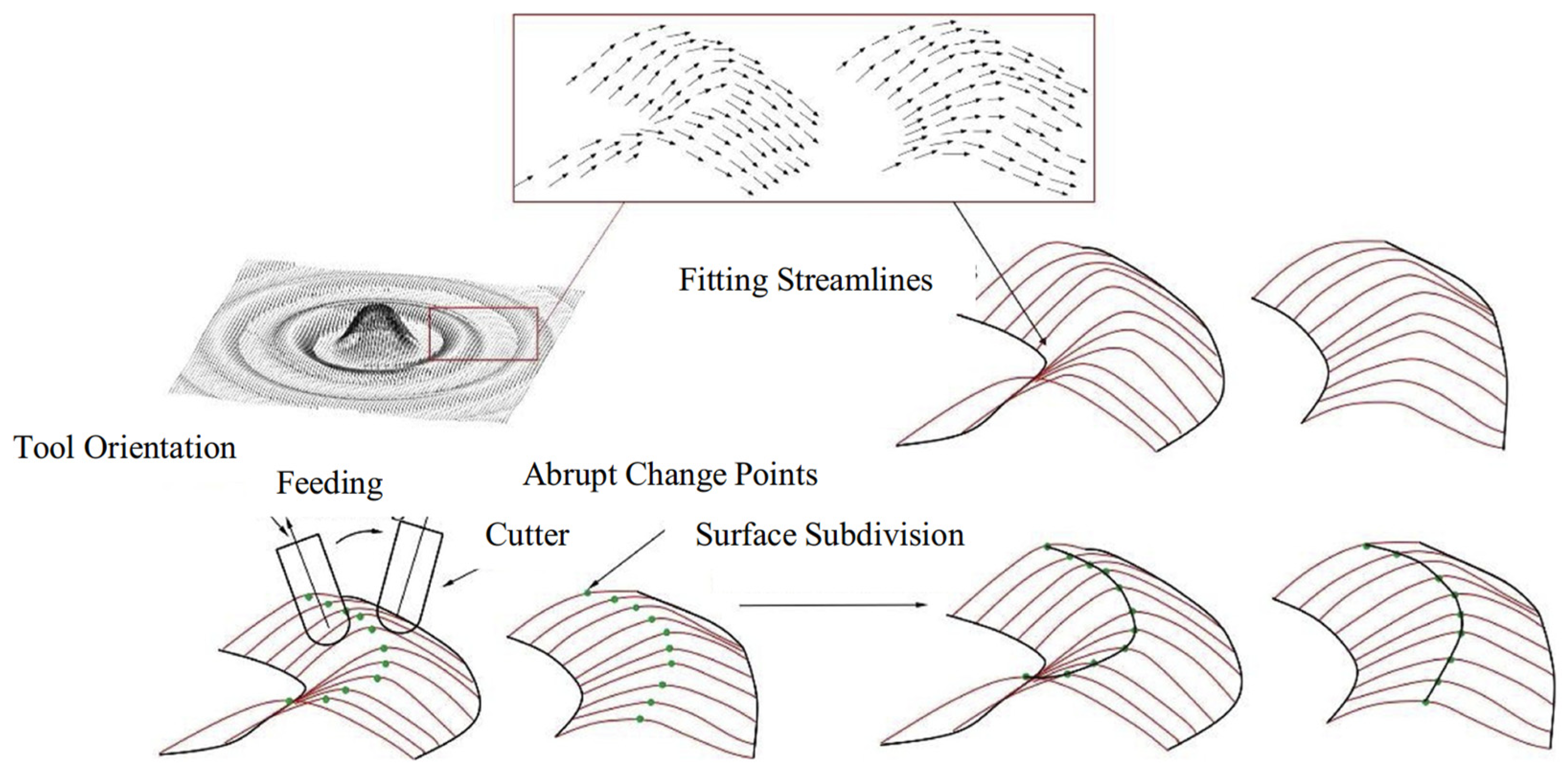
However, there is a significant deficiency in current studies on tool path generation, i.e., they mainly focus on surface segmentation refinement and direct generation of tool trajectories, while neglecting the optimization of tool trajectory topology. This leads to the fact that the existing sub-regional machining strategies only achieve the optimal effect locally and improve the machining efficiency, but fail to provide an effective guiding strategy for the global optimization of tool trajectories. To address this limitation, Ma et al. [80] proposed an innovative tool trajectory topology design method, which is particularly suitable for complex surface machining. The method is based on the vector field of tool feed direction in sub-regional machining, taking into account the machine tool’s feed direction preference and kinematic performance constraints. By introducing the optimal feed direction and constructing the vector field, the method realizes the fine surface segmentation of complex surfaces to achieve the topology design of the tool trajectory, and then realizes the tool trajectory to achieve the global optimization effect. The trajectory obtained based on the vector field subdivision method is shown in Figure 11. In summary, the comparative analysis of the mainstream methods mentioned above is shown in Table 1.

4. Conclusions and Outlook

At present, the research on CNC machining technology for complex surfaces has made great progress in machining trajectory planning, vector field-based tool attitude optimization, and vector field-based tool position optimization, etc., but it is still difficult to meet the demand for high-performance manufacturing of complex surfaces, and the deficiencies and future development trends are summarized as follows:
(1)
The traditional tool path planning methods are still confined to the point-by-point trajectory design at the purely geometric level, and the layout form depends on the selection of the initial path. Additionally, there are fewer methods to consider the tool trajectory at the integrated level of geometry, kinematics, and dynamics, which are not able to take into account the physical characteristics of the surface geometry and have difficulty realizing the overall control of the tool trajectory. Therefore, it is necessary to consider from the perspective of geometry, kinematics, and dynamics.
(2)
Regarding the optimization of tool posture based on vector field, the current research mainly focuses on the smoothness of the feed vector; however, the consideration factors are too single. Therefore, the multimodal vector field data, such as the CAD model, feed speed curve, spindle torsion angle, vibration spectrum, etc., should be integrated to establish cross-modal correlation through models similar to the Contrastive Language–Image Pretraining model (CLIP-like model), to realize the comprehensive optimization of tool attitude.
(3)
In the optimization of tool position based on vector field, the current is mainly based on vector field from the machining bandwidth, the best motion performance, the minimum energy consumption, the maximum material removal rate, the maximum feed rate, and so on, as the goal to achieve the optimization of the tool path. However, the above optimization objectives are mainly for the optimization of the target offline value. In the future, with the development of artificial intelligence, digital twin, image processing technologies [81,82], and wireless sensing technology, based on the sensor feedback real-time correction vector field, dynamic adjustment of the tool position, our goal is to achieve the machining process of “perception—decision-making—execution” of the closed-loop optimization, and then realize the intelligent, real-time, multi-objective optimization of complex surfaces of high-precision machining.

Author Contributions

Conceptualization, S.X. and Z.L.; methodology, Z.L.; formal analysis, S.X. and Z.L.; investigation, S.X.; data curation, S.X. and Z.L.; writing—original draft preparation, S.X.; writing—review and editing, Z.L.; supervision, Z.L.; project administration, Z.L.; funding acquisition, Z.L. All authors have read and agreed to the published version of the manuscript.

Funding

This research was funded by the Natural Science Foundation of Hunan Province, grant number 2020JJ5577.

Data Availability Statement

The original contributions presented in this study are included in the article. Further inquiries can be directed to the corresponding author.

Conflicts of Interest

The authors declare no conflicts of interest.

References

  1. Li, X.; Huang, T.; Zhao, H.; Zhang, X.; Yan, S.; Dai, X.; Ding, H. A review of recent advances in machining techniques of complex surfaces. Sci. China Technol. Sci. 2022, 65, 1915–1939. [Google Scholar] [CrossRef]
  2. Liu, H.; Xing, F. Tool axis vector optimization based on automatic smoothing rotary angles of five-axis machining for laser additive manufacturing. Int. J. Adv. Manuf. Technol. 2024, 134, 3481–3493. [Google Scholar] [CrossRef]
  3. Masood, A.; Siddiqui, R.; Pinto, M.; Rehman, H.; Khan, M.A. Tool Path Generation, for Complex Surface Machining, Using Point Cloud Data. Procedia CIRP 2015, 26, 397–402. [Google Scholar] [CrossRef]
  4. Behera, R.; Chan, T.-C.; Yang, J.-S. Innovative Structural Optimization and Dynamic Performance Enhancement of High-Precision Five-Axis Machine Tools. J. Manuf. Mater. Process. 2024, 8, 181. [Google Scholar] [CrossRef]
  5. Zhu, D.; Feng, X.; Xu, X.; Yang, Z.; Li, W.; Yan, S.; Ding, H. Robotic grinding of complex components: A step towards efficient and intelligent machining—Challenges, solutions, and applications. Robot. Comput. Manuf. 2020, 65, 101908. [Google Scholar] [CrossRef]
  6. Makhanov, S.S. Vector fields for five-axis machining. A survey. Int. J. Adv. Manuf. Technol. 2022, 122, 533–575. [Google Scholar] [CrossRef]
  7. Jignasu, A.; Rurup, J.D.; Secor, E.B.; Krishnamurthy, A. NURBS-based path planning for aerosol jet printing of conformal electronics. J. Manuf. Process. 2024, 118, 187–194. [Google Scholar] [CrossRef]
  8. Ma, J.W.; Hu, G.Q.; Qin, F.Z.; Li, G.-L.; Qu, Z.-W. Optimization method of tool axis vector based on kinematical characteristics of rotary feed axis for curved surface machining. Int. J. Adv. Manuf. Technol. 2019, 100, 2007–2020. [Google Scholar] [CrossRef]
  9. Ma, J.-W.; Hu, G.-Q.; Qin, F.-Z.; Li, G.-L.; Qu, Z.-W.; Liu, Y. Global tool axis vector optimization based on the minimum angular acceleration of rotary axes. Int. J. Adv. Manuf. Technol. 2020, 107, 2121–2136. [Google Scholar] [CrossRef]
  10. Zhao, P.; Liu, Z.; Li, Z.; Cao, Z. Research on tool axis vector optimization when face milling complex surfaces. Int. J. Adv. Manuf. Technol. 2023, 128, 5081–5099. [Google Scholar] [CrossRef]
  11. Gong, Z.; Li, B.; Zhang, H.; Ye, P. Tool orientation optimization method based on ruled surface using genetic algorithm. Int. J. Adv. Manuf. Technol. 2021, 118, 571–584. [Google Scholar] [CrossRef]
  12. Mi, Z.; Yuan, C.-M.; Ma, X.; Shen, L.-Y. Tool orientation optimization for 5-axis machining with C-space method. Int. J. Adv. Manuf. Technol. 2016, 88, 1243–1255. [Google Scholar] [CrossRef]
  13. Yuan, C.; Mi, Z.; Jia, X.; Lin, F.; Shen, L. Tool Orientation Optimization and Path Planning for 5-Axis Machining. J. Syst. Sci. Complex. 2020, 34, 83–106. [Google Scholar] [CrossRef]
  14. Zhang, Y.; Li, Y.; Xu, K. Reinforcement learning–based tool orientation optimization for five-axis machining. Int. J. Adv. Manuf. Technol. 2022, 119, 7311–7326. [Google Scholar] [CrossRef]
  15. .Chu, M.; Bohez Erik, L.J.; Makhanov Stanlislav, S.; Munlin, M.; Phien, H.N.; Tabucanon, M.T. On 5-axis freeform surface machining optimization: Vector field clustering approach. Int. J. CAD/CAM 2005, 5, 1–10. [Google Scholar]
  16. Li, H.; Tutunea-Fatan, O.R.; Feng, H.-Y. An improved tool path discretization method for five-axis sculptured surface machining. Int. J. Adv. Manuf. Technol. 2006, 33, 994–1000. [Google Scholar] [CrossRef]
  17. Yao, Q. Five-Coordinate CNC Machining Space Cam CAD/CAM System. Master’s Thesis, Dalian University of Technology, Dalian, China, 2007. [Google Scholar] [CrossRef]
  18. Loney, G.C.; Ozsoy, T.M. NC machining of free form surfaces. Comput. Des. 1987, 19, 85–90. [Google Scholar] [CrossRef]
  19. Cho, J.H.; Kim, J.; Kim, K. CNC tool path planning for multi-patch sculptured surfaces. Int. J. Prod. Res. 2000, 38, 1677–1687. [Google Scholar] [CrossRef]
  20. He, W.; Lei, M.; Bin, H. Iso-parametric CNC tool path optimization based on adaptive grid generation. Int. J. Adv. Manuf. Technol. 2008, 41, 538–548. [Google Scholar] [CrossRef]
  21. Ding, S.; Mannan, M.; Poo, A.; Yang, D.; Han, Z. Adaptive iso-planar tool path generation for machining of free-form surfaces. Comput. Des. 2003, 35, 141–153. [Google Scholar] [CrossRef]
  22. Han, Z.; Yang, D.C.H.; Chuang, J.-J. Isophote-based ruled surface approximation of free-form surfaces and its application in NC machining. Int. J. Prod. Res. 2001, 39, 1911–1930. [Google Scholar] [CrossRef]
  23. Kim, B.; Choi, B. Guide surface based tool path generation in 3-axis milling: An extension of the guide plane method. Comput. Des. 2000, 32, 191–199. [Google Scholar] [CrossRef]
  24. Han, F.; Gu, Z.; Zhao, Y.; Zhang, C. Elliptic Cycloid Tool Path Optimization of Impeller Rough Machining Based on Parame-ter Maping. China Mech. Eng. 2024, 35, 438. [Google Scholar]
  25. Giri, V.; Bezbaruah, D.; Bubna, P.; Choudhury, A.R. Selection of master cutter paths in sculptured surface machining by employing curvature principle. Int. J. Mach. Tools Manuf. 2005, 45, 1202–1209. [Google Scholar] [CrossRef]
  26. Suresh, K.; Yang, D.C.H. Constant Scallop-height Machining of Free-form Surfaces. J. Eng. Ind. 1994, 116, 253–259. [Google Scholar] [CrossRef]
  27. Shi, B.G.; Lei, Y.; Yan, G.G. Surface mapping method for generating tool trajectories for equi-residual ring-cut machining. J. Eng. Graph. 2005, 3, 1217. [Google Scholar]
  28. Hauth, S.; Richterich, C.; Glasmacher, L.; Linsen, L. Constant cusp toolpath generation in configuration space based on offset curves. Int. J. Adv. Manuf. Technol. 2010, 53, 325–338. [Google Scholar] [CrossRef]
  29. Hao, S.Z.; Duroobi, A.A.; Chen, W.L.; He, L. Calculation of multi-axis machining stepover with equal residual heights for annular knives. J. Nanjing Univ. Aeronaut. Astronaut. 2012, 44, 538–542. [Google Scholar] [CrossRef]
  30. Zhao, S.T.; Zhao, D.B.; Fu, Y.Y.; Lu, Y.H.; Liu, K. Improved tool path generation algorithm for machining free-form surfaces with equal residual heights. J. Nanjing Univ. Aeronaut. Astronaut. 2012, 44, 240–245. [Google Scholar] [CrossRef]
  31. Ye, P.Q.; Chen, T.; Wang, J.S. Planning algorithms for tool trajectories in fivecoordinate CNC machining of complex surfaces. Mech. Sci. Technol. 2004, 8, 883–886. [Google Scholar]
  32. Feng, H.-Y.; Li, H. Constant scallop-height tool path generation for three-axis sculptured surface machining. Comput. Des. 2002, 34, 647–654. [Google Scholar] [CrossRef]
  33. Tournier, C.; Duc, E. Iso-scallop tool path generation in 5-axis milling. Int. J. Adv. Manuf. Technol. 2004, 25, 867–875. [Google Scholar] [CrossRef]
  34. Tournier, C.; Duc, E. A Surface Based Approach for Constant Scallop Height Tool-Path Generation. Int. J. Adv. Manuf. Technol. 2002, 19, 318–324. [Google Scholar] [CrossRef][Green Version]
  35. Kim, T. Constant cusp height tool paths as geodesic parallels on an abstract Riemannian manifold. Comput. Des. 2007, 39, 477–489. [Google Scholar] [CrossRef]
  36. Wang, L.; Li, Y.; Yang, H.; Li, J. Surface-centric toolpath optimization via cutter location surface reconstruction for addressing neighboring inconsistency in CNC machining. J. Manuf. Process. 2025, 150, 933–948. [Google Scholar] [CrossRef]
  37. Raju, R.S.U.; Kumar, K.R.; Vargish, K.; Kumar, M.B. Machine learning based surface roughness assessment via CNC spindle bearing vibration. Int. J. Interact. Des. Manuf. (IJIDeM) 2024, 19, 477–494. [Google Scholar] [CrossRef]
  38. Chen, X.B.; Liao, W.H.; Wu, H.B.; Sun, Q.P.; Chen, Q.L. An algorithm for generating knife-rails with equal residual heights on triangular mesh surfaces. J. Comput. Aided Des. Graph. 2009, 21, 1800–1804. [Google Scholar]
  39. Jun, C.-S.; Cha, K.; Lee, Y.-S. Optimizing tool orientations for 5-axis machining by configuration-space search method. Comput. Des. 2003, 35, 549–566. [Google Scholar] [CrossRef]
  40. Lauwers, B.; Dejonghe, P.; Kruth, J.P. Optimal and collision free tool posture in five-axis machining through the tight integration of tool path generation and machine simulation. Comput. Aided Des. 2003, 35, 421–432. [Google Scholar] [CrossRef]
  41. Ho, M.-C.; Hwang, Y.-R.; Hu, C.-H. Five-axis tool orientation smoothing using quaternion interpolation algorithm. Int. J. Mach. Tools Manuf. 2003, 43, 1259–1267. [Google Scholar] [CrossRef]
  42. Wang, N.; Tang, K. Automatic generation of gouge-free and angular-velocity-compliant five-axis toolpath. Comput. Des. 2007, 39, 841–852. [Google Scholar] [CrossRef]
  43. Sun, Y.; Bao, Y.; Kang, K.; Guo, D. A cutter orientation modification method for five-axis ball-end machining with kinematic constraints. Int. J. Adv. Manuf. Technol. 2013, 67, 2863–2874. [Google Scholar] [CrossRef]
  44. Castagnetti, C.; Duc, E.; Ray, P. The Domain of Admissible Orientation concept: A new method for five-axis tool path optimisation. Comput. Des. 2008, 40, 938–950. [Google Scholar] [CrossRef]
  45. Jia, X.; Luo, J.; Li, K.; Wang, C.; Li, Z.; Wang, M.; Jiang, Z.; Veiko, V.P.; Duan, J. Ultrafast laser welding of transparent materials: From principles to applications. Int. J. Extrem. Manuf. 2025, 7, 032001. [Google Scholar] [CrossRef]
  46. Jia, X.; Lin, J.; Li, Z.; Wang, C.; Li, K.; Wang, C.; Duan, J. Continuous wave laser ablation of alumina ceramics under long focusing condition. J. Manuf. Process. 2025, 134, 530–546. [Google Scholar] [CrossRef]
  47. Li, Z.; Lin, J.; Jia, X.; Li, X.; Li, K.; Wang, C.; Sun, K.; Ma, Z.; Duan, J. High efficiency femtosecond laser ablation of alumina ceramics under the filament induced plasma shock wave. Ceram. Int. 2024, 50, 47472–47484. [Google Scholar] [CrossRef]
  48. Moodleah, S.; Bohez, E.; Makhanov, S. Five-axis machining of STL surfaces by adaptive curvilinear toolpaths. Int. J. Prod. Res. 2016, 54, 7296–7329. [Google Scholar] [CrossRef]
  49. Kumazawa, G.H.; Feng, H.Y.; Fard, M.J.B. Preferred feed direction field: A new tool path generation method for efficient sculptured surface machining. Comput. Aided Des. 2015, 67, 1–12. [Google Scholar] [CrossRef]
  50. Kim, T.; Sarma, S.E. Toolpath generation along directions of maximum kinematic performance; a first cut at machine-optimal paths. Comput. Des. 2002, 34, 453–468. [Google Scholar] [CrossRef]
  51. Xu, K.; Luo, M.; Tang, K. Machine based energy-saving tool path generation for five-axis end milling of freeform surfaces. J. Clean. Prod. 2016, 139, 1207–1223. [Google Scholar] [CrossRef]
  52. Ye, T.; Xiong, C.; Xiong, Y.; Zhao, C. Kinematics constrained five-axis tool path planning for high material removal rate. Sci. China Technol. Sci. 2011, 54, 3155–3165. [Google Scholar] [CrossRef]
  53. Huang, K.; Lee, C.-H.; Yan, C.; Gong, H. Study on a 2D field-based multi-objective tool-axis optimization algorithm based on covariant field theory for five-axis tool path generation. Int. J. Adv. Manuf. Technol. 2020, 108, 11–22. [Google Scholar] [CrossRef]
  54. He, S.P.; Xiao, Z.F.; Chen, J.J.; Xu, G.; Zheng, Y. Automatic Quad Mesh Generation of 2D Domain Based on Vector Field. J. Comput.-Aided Des. Comput. Graph. 2020, 32, 730–739. [Google Scholar]
  55. Zhang, K.; Tang, K. An efficient greedy strategy for five-axis tool path generation on dense triangular mesh. Int. J. Adv. Manuf. Technol. 2014, 74, 1539–1550. [Google Scholar] [CrossRef]
  56. Moodleah, S.; Makhanov, S.S. 5-axis machining using a curvilinear tool path aligned with the direction of the maximum removal rate. Int. J. Adv. Manuf. Technol. 2015, 80, 65–90. [Google Scholar] [CrossRef]
  57. Manav, C.; Bank, H.S.; Lazoglu, I. Intelligent toolpath selection via multi-criteria optimization in complex sculptured surface milling. J. Intell. Manuf. 2011, 24, 349–355. [Google Scholar] [CrossRef]
  58. Lamikiz, A.; López De Lacalle, L.N.; Sanchez, J.A.; Salgado, M.A. Cutting force integration at the CAM stage in the high-speed milling of complex surfaces. Int. J. Comput. Integr. Manuf. 2005, 18, 586–600. [Google Scholar] [CrossRef]
  59. Fard, M.J.B.; Feng, H.-Y. Effect of tool tilt angle on machining strip width in five-axis flat-end milling of free-form surfaces. Int. J. Adv. Manuf. Technol. 2008, 44, 211–222. [Google Scholar] [CrossRef]
  60. Fard, M.J.B.; Feng, H.-Y. Effective Determination of Feed Direction and Tool Orientation in Five-Axis Flat-End Milling. J. Manuf. Sci. Eng. 2010, 132, 061011. [Google Scholar] [CrossRef]
  61. Liu, X.; Li, Y.; Ma, S.; Lee, C.-H. A tool path generation method for freeform surface machining by introducing the tensor property of machining strip width. Comput. Des. 2015, 66, 1–13. [Google Scholar] [CrossRef]
  62. Wang, J.; Luo, M.; Zhang, D.H. A global space–based approach for wide strip flank milling of freeform surface with a barrel cutter. Int. J. Comput. Integr. Manuf. 2018, 32, 92–104. [Google Scholar] [CrossRef]
  63. Qian, L.; Zhang, L.; Gao, Q.; Yang, J. Optimization of tool axis vector for mirror milling of thin-walled parts based on kinematic constraints. Int. J. Adv. Manuf. Technol. 2022, 124, 847–861. [Google Scholar] [CrossRef]
  64. Dang, L.V.; Makhanov, S. Vector Field Analysis for optimization of the Tool Path of the Five-Axis Milling Machine. In Proceedings of the 2018 17th European Control Conference (ECC), Limassol, Cyprus, 12–15 June 2018; pp. 1–6. [Google Scholar]
  65. Shin, S.-J.; Woo, J.; Rachuri, S. Energy efficiency of milling machining: Component modeling and online optimization of cutting parameters. J. Clean. Prod. 2017, 161, 12–29. [Google Scholar] [CrossRef]
  66. Pavanaskar, S.; Pande, S.; Kwon, Y.; Hu, Z.; Sheffer, A.; McMains, S. Energy-efficient vector field based toolpaths for CNC pocketmachining. J. Manuf. Process. 2015, 20, 314–320. [Google Scholar] [CrossRef]
  67. Hu, P.; Tang, K. Five-axis tool path generation based on machine-dependent potential field. Int. J. Comput. Integr. Manuf. 2015, 29, 636–651. [Google Scholar] [CrossRef]
  68. Makhanov, S.S. Decomposition of the Vector Field of Preferred Directions for Optimization of Five-Axis Machining. In Proceedings of the 2020 4th International Conference on Materials Engineering and Nano Sciences (ICMENS), Pattaya, Thailand, 13–15 March 2020; Volume 840, p. 012005. [Google Scholar]
  69. Wang, Z.; Liu, S.; Liu, L.; Zou, Q.; Fu, X.-M. Computing smooth preferred feed direction fields with high material removal rates for efficient CNC tool paths. Comput. Des. 2023, 164, 103591. [Google Scholar] [CrossRef]
  70. Chiou, C.-J.; Lee, Y.-S. A machining potential field approach to tool path generation for multi-axis sculptured surface machining. Comput. Des. 2002, 34, 357–371. [Google Scholar] [CrossRef]
  71. Sun, S.; Sun, Y.; Xu, J.; Lee, Y.-S. Iso-Planar Feed Vector-Fields-Based Streamline Tool Path Generation for Five-Axis Compound Surface Machining With Torus-End Cutters. J. Manuf. Sci. Eng. 2018, 140, 071013. [Google Scholar] [CrossRef]
  72. Sun, Y.W.; Shu, C.L.; Liu, J. Research on CNC machining trajectory design method based on vector analysis. J. Mech. Eng. 2005, 41, 160–164, 170. [Google Scholar] [CrossRef]
  73. Sun, Y.; Sun, S.; Xu, J.; Guo, D. A unified method of generating tool path based on multiple vector fields for CNC machining of compound NURBS surfaces. Comput. Des. 2017, 91, 14–26. [Google Scholar] [CrossRef]
  74. Shen, H.-Y.; Sun, Y.-F.; Zhang, L.-C.; Fu, J.-Z. A parameter zone subdivision method for rotary axes motion optimization in five-axis toolpath generation using inverse evaluation mechanism. Int. J. Adv. Manuf. Technol. 2018, 98, 3115–3131. [Google Scholar] [CrossRef]
  75. Li, Z.; Tang, K. Partition-based five-axis tool path generation for freeform surface machining using a non-spherical tool. J. Manuf. Syst. 2021, 58, 248–262. [Google Scholar] [CrossRef]
  76. Jia, Z.-Y.; Zhao, X.-X.; Ma, J.-W.; Chen, S.-Y.; Qin, F.-Z.; Liu, Z. Toolpath generation in sub-regional processing with constraint of constant scallop-height at boundary for complex curved surface. Precis. Eng. 2019, 55, 217–230. [Google Scholar] [CrossRef]
  77. Wang, Y.; Yan, C.; Yang, J.; Lee, C.-H. Tool path generation algorithm based on covariant field theory and cost functional optimization and its applications in blade machining. Int. J. Adv. Manuf. Technol. 2016, 90, 927–943. [Google Scholar] [CrossRef]
  78. Dutta, N.; Zhang, T.; Fang, G.; Yigit, I.E.; Wang, C.C.L. Vector Field-Based Volume Peeling for Multi-Axis Machining. J. Comput. Inf. Sci. Eng. 2023, 24, 051001. [Google Scholar] [CrossRef]
  79. Liu, X.; Li, Y.; Xu, X. A region-based tool path generation approach for machining freeform surfaces by applying machining strip width tensor. Int. J. Adv. Manuf. Technol. 2018, 98, 3191–3204. [Google Scholar] [CrossRef]
  80. Ma, J.-W.; Lu, X.; Li, G.-L.; Qu, Z.-W.; Qin, F.-Z. Toolpath topology design based on vector field of tool feeding direction in sub-regional processing for complex curved surface. J. Manuf. Process. 2020, 52, 44–57. [Google Scholar] [CrossRef]
  81. Pimenov, D.Y.; da Silva, L.R.R.; Ercetin, A.; Der, O.; Mikolajczyk, T.; Giasin, K. State-of-the-art review of applications of image processing techniques for tool condition monitoring on conventional machining processes. Int. J. Adv. Manuf. Technol. 2023, 130, 57–85. [Google Scholar] [CrossRef]
  82. Ercetin, A.; Der, O.; Akkoyun, F.; Chandrashekarappa, M.P.G.; Şener, R.; Çalışan, M.; Olgun, N.; Chate, G.; Bharath, K.N. Review of Image Processing Methods for Surface and Tool Condition Assessments in Machining. J. Manuf. Mater. Process. 2024, 8, 244. [Google Scholar] [CrossRef]
Figure 1. Vector field: (a) 2D vector field; (b) 3D vector field.
Symmetry 17 01300 g001
Figure 2. Example of a compound sculptured surface and the tool path generation: (a) an example of compound sculptured surface and CC path generation; (b) example of CC path and the tool path generation; (c) tool motion on path A of machining multiple surface [39].
Symmetry 17 01300 g002
Figure 3. Results of optimization: (a) constrained path; (b) unconstrained path distance not minimized; (c) unconstrained path distance minimized [44].
Symmetry 17 01300 g003aSymmetry 17 01300 g003b
Figure 4. Processing bandwidth vector field on parameter domains: (a) model surface; (b) vector field mapped onto a parameter field [49].
Symmetry 17 01300 g004
Figure 5. Final adjustment of the surface cutter point [63].
Symmetry 17 01300 g005
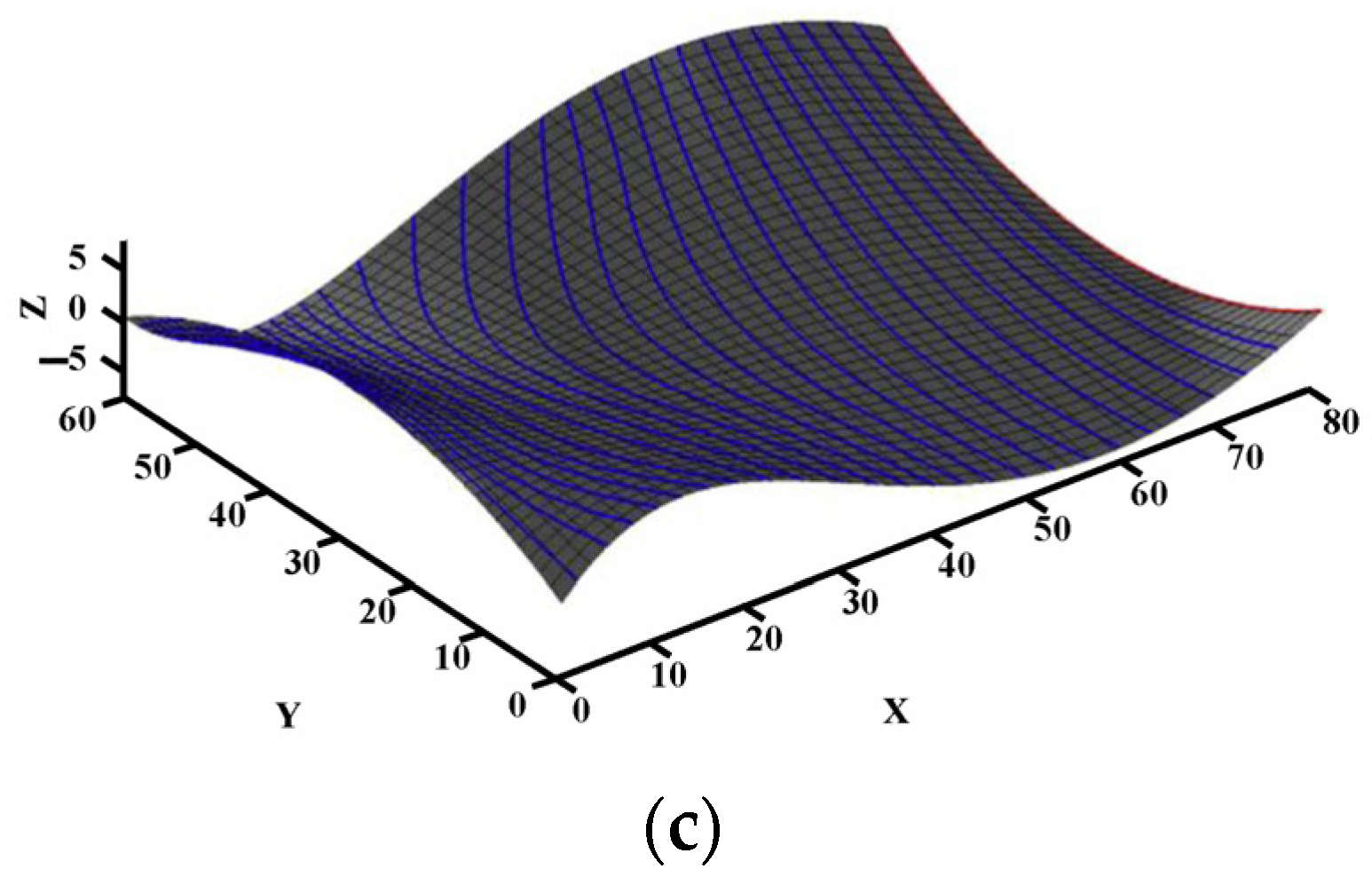
Figure 6. Surfaces and Simulation Results: (a) a test STL surface; (b) flattened surface; (c) vector field and clusters; (d) bounding box grids; (e) ISO path; (f) the proposed VF method [64].
Symmetry 17 01300 g006aSymmetry 17 01300 g006b
Figure 7. CC curves generated by (a) the MBEPF-Based Tool Path Generation Algorithm; (b) the first round of the MBEPF-Based Tool Path; (c) the boundary conformed iso-scallop height tool path scheme [51].
Symmetry 17 01300 g007aSymmetry 17 01300 g007b
Figure 8. The machining results: (a) adaptive grid; (b) SFC-tool path; (c) ISO zigzag; (d) the VF method [68].
Symmetry 17 01300 g008
Figure 9. Surface vector field: (a) boundary tool vector field; (b) initial surface tool vector field; (c) optimized surface tool vector field [53].
Symmetry 17 01300 g009
Figure 10. Streamlined knife on a composite surface based on smooth coupled splicing of streamline fields trajectory construction (geology): (a) parameter-domain upflow field G1-continuous splicing; (b) smooth tool paths on model surfaces [73].
Symmetry 17 01300 g010
Figure 11. Reason and method of surface subdivision [78].
Symmetry 17 01300 g011
Table 1. The comparative analysis of the mainstream methods.
Method CategorySpecific MethodsAdvantagesDisadvantagesApplicability
Conventional Tool Path PlanningIsoparametric Line MethodSimple and practical; widely used in multi-coordinate CNC machining.Deviation between parameter space and Euclidean space; potential undercutting.Parametric surfaces with relatively regular mesh structures.
Truncated Plane MethodGood applicability; suitable for sheared parametric surfaces.Complex calculations (solving nonlinear equations); long tool path due to conservative line spacing.General complex surfaces; widely used in CAD/CAM systems.
Iso-Illumination Line MethodAccurate positioning; applicable to five-axis CNC machining.Initially designed for surface continuity checking; limited in complex geometries.Surfaces requiring high positioning accuracy.
Mapping MethodTransforms 3D problems to 2D for easier calculation.Mapping quality affects trajectory accuracy; challenging for highly complex surfaces.Curved cavity-like structures and multi-feature combination surfaces.
Equal Residual Height MethodGuarantees both machining efficiency and accuracy.Large calculation volume; lower efficiency in the early stage (alleviated by modern computing).Parametric surfaces and mesh surface models with high-precision requirements.
Vector Field-Based Tool Path PlanningTool Attitude OptimizationImproves machining smoothness and kinematic performance; reduces tool vibration.Some methods ignore machine tool rotary axis performance; may cause servo tracking errors.Scenarios requiring high smoothness, such as high-speed milling.
Tool Position Optimization (Maximum Bandwidth)Enhances machining efficiency by maximizing cutting width.High computational complexity; dependent on machining experience and equipment.Large or structurally complex parts.
Tool Position Optimization (Kinematic Performance)Ensures speed smoothness, stability, and load balancing.Requires comprehensive consideration of multi-axis constraints; complex parameter tuning.High-speed and high-precision machining processes.
Tool Position Optimization (Minimum Energy Consumption)Reduces production cost by minimizing energy usage.Limited by machining task requirements; needs balance with accuracy.Energy-sensitive manufacturing environments.
Disclaimer/Publisher’s Note: The statements, opinions and data contained in all publications are solely those of the individual author(s) and contributor(s) and not of MDPI and/or the editor(s). MDPI and/or the editor(s) disclaim responsibility for any injury to people or property resulting from any ideas, methods, instructions or products referred to in the content.