Abstract
Tall-pier girder bridges with fluid viscous dampers (FVDs) are widely used in earthquake-prone mountainous areas. However, the influence of higher-order modes and near-field earthquakes on tall piers has rarely been studied. Based on an asymmetric tall-pier girder bridge, a finite element model is established, and the parameters of FVDs are optimized using SAP2000. The higher-order mode effects on tall piers are explored by proportionally reducing the pier heights. The pulse effects of near-field earthquakes on FVD mitigation and higher-order modes are analyzed. The optimal FVDs can coordinate the force distribution among tall piers, effectively reducing displacement responses and internal forces. Due to higher-order modes, the internal force envelopes of tall piers exhibit concave-convex distributions. As pier heights decrease, the internal force envelopes gradually become linear, implying reduced higher-order mode effects. Long-period pulse-like motions produce the maximum seismic responses because the slender tall-pier bridge is sensitive to high spectral accelerations in medium-to-long periods. The higher-order modes are more easily excited by near-field motions with large spectral values in the high-frequency range. Overall, FVDs can simultaneously reduce the seismic responses of tall piers and diminish the influence of higher-order modes.
1. Introduction
Western China, characterized by complex geological conditions and deep valleys, is widely recognized as seismically active zones [1]. In recent decades, a large number of asymmetric tall-pier bridges have been constructed in Western China due to their suitability for complex and mountainous terrain [2]. Given the frequent near-field earthquakes (e.g., Wenchuan [3], Yushu earthquake [4], and Lushan earthquake [5]), the seismic performance of tall-pier girder bridges in these zones is of critical importance [6].
To improve the seismic performance of bridges, a common strategy is the isolation bearings, including friction pendulum bearings (FPBs) [7,8,9], lead-rubber bearings (LRBs) [10,11,12], and high-damping rubber bearings (HDRBs) [13,14]. These bearings achieve seismic isolation by extending the structure’s fundamental natural period and dissipating earthquake energy [15]. For bridges with mid- and short-piers, these isolation bearings can significantly reduce the inertial forces transmitted to the substructure while increasing the displacements of bearing and girder [7,8,9,10,11,12,13,14]. However, bridges with tall piers or towers often have long fundamental periods, so isolation bearings that extend structural periods are no longer suitable [16]. To address this issue, fluid viscous dampers (FVDs) with a symmetric hysteretic rule are an alternative device to enhance the seismic performance of bridges by dissipating energy and limiting girder displacement [17].
To date, FVDs have been widely adopted in various types of bridges due to their stable performance and clear mitigating mechanism. For instance, Wang et al. [18] confirmed that multiple viscous-inertial dampers can effectively suppress the transverse responses of continuous girder bridges. Liu et al. [19] investigated the dynamic responses of steel box girder bridges and found that FVDs significantly reduced bearing shear forces. Zhong et al. [20] integrated probabilistic seismic demand models with Monte Carlo simulations to evaluate the optimal parameters of FVDs in cable-stayed bridges. Liang et al. [21] systematically analyzed four layout schemes of FVDs applied to the long-span cable-stayed bridges, evaluated their seismic control performance, and further optimized key parameters to enhance damping efficiency and energy dissipation capacity. Jing et al. [22] proposed a combined system of cable limiters and FVDs to efficiently control the longitudinal vibrations of suspension bridges. Bas et al. [23] found that FVDs can effectively control longitudinal deck displacement of the Bosphorus Bridge, but more concentrated loads are transmitted to the pylons, which leads to increased bending moments and shear forces at the bottom of the tower.
The above investigations demonstrate that FVDs can effectively reduce internal forces and displacement responses in bridges during seismic excitation. However, existing publications mainly focus on the continuous girder bridges with medium-to-short piers [18,19], cable-stayed bridges [20,21], and suspension bridges [22,23]. Unlike the FVDs arranged at the mid lateral beam of the tower, the FVDs for tall-pier girder bridges are set as the pier top, exhibiting different seismic behaviors from the cable-supported bridge system [20,21,22,23]. Compared to medium-to-short piers, inertial forces induced by self-mass of tall piers are considerable, and can be larger than those from the superstructure [24,25]. Their seismic performance is significantly affected by higher-order modes, frequently leading to mid plastic hinges in piers [26]. Moreover, tall-pier girder bridges feature long fundamental periods, which amplify dynamic responses under pulse-type motions containing long-period velocity pulses [27]. Thus, it is imperative to assess the seismic performance of FVD-equipped tall-pier girder bridges under near-field earthquakes.
In this study, taking an asymmetric tall-pier girder bridge as a case study, a three-dimensional finite element model is built using SAP2000 (Beijing Construction Information Solution Engineering Consulting, Beijing, China). The mechanical behavior of the FVD is idealized as the symmetric hysteretic rule (Maxwell model [28]). The FVD parameters including the damping coefficient C and velocity exponent α are optimized based on the longitudinal seismic responses of the bridge. The influence of higher-order modes on tall piers is examined via pier height reductions. In addition, the pulse effects of near-field earthquakes on both FVD efficacy and the higher-order mode are explored. Finally, key conclusions are summarized according to the analysis and discussion.
2. Description and Modeling of the Bridge
2.1. Description of the Bridge
The general layout of a multi-span tall-pier composite girder bridge is shown in Figure 1. The bridge has a span arrangement of (60 + 70 + 70 + 70 + 40 + 40) m, with a total length of 350 m. The superstructure comprises double-box prestressed composite girders, while the substructure includes tall piers with variable hollow cross-sections. C30 concrete is used for piles and pile caps, while C40 concrete is specified for piers and pier caps.
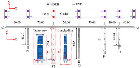
Figure 1.
General layout of the bridge (unit: m).
Each box girder is vertically supported on the piers by two high damping rubber bearings (HDRBs). These bearings are placed between the concrete bearing pads on the pier cap beams and the embedded steel plates at the girder bottom. Among all the bridge piers, only pier P2 is a fixed pier, while the others are movable piers. Pier P2 is selected as the fixed pier because it is the tallest pier in the bridge and has a greater flexibility. If a shorter pier is selected as the fixed pier, its higher stiffness would result in smaller deformations under earthquakes, which is more likely to cause seismic damage. The other piers are designed as movable piers, allowing the bridge to undergo deformation during earthquakes. The arrangement of the HDRBs and FVDs is illustrated in Figure 1. The parameters for HDRBs are determined based on vertical loads and Specification JT/T 842-2012 [29].
2.2. Analytical Model of the Bridge
A spatial finite element model of the bridge is established using SAP2000, as shown in Figure 2a. Steel truss girders, piers, pile caps, and girders are modeled using elastic beam elements. Permanent loads primarily include the self-weight of the structure and the second-phase dead loads. HDRBs are represented using the bilinear hysteretic rule (Figure 2b). FVDs are modeled using the symmetric hysteretic rule based on the Maxwell model (Figure 2c) [28]. The pile–soil interaction is accounted for using the m-method (Figure 2d) [30]. The m values are derived from the geotechnical report and Specification JTG 3363—2019 [31], as shown in Table 1.
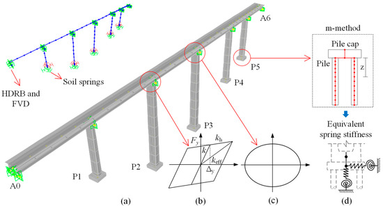
Figure 2.
Analytical model: (a) Numerical discretization; (b) Bilinear hysteretic rule for HDRB; (c) Symmetric hysteretic rule for FVD; (d) Pile–soil interaction.

Table 1.
Parameters for the m-method.
According to the site-specific seismic safety assessment report, the bridge is located on a medium-stiff soil site with a characteristic period of 0.45 s. The peak ground acceleration (PGA) is 0.3 g. The El Centro wave is chosen as the input excitation for the optimization of the FVD. The corresponding acceleration response spectrum and time history are shown in Figure 3.
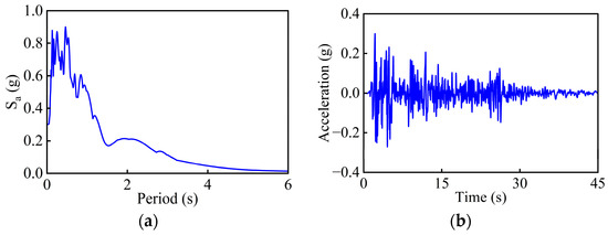
Figure 3.
El Centro wave: (a) Acceleration response spectrum; (b) Acceleration time history.
2.3. Dynamic Characteristics of the Bridge
Accurately understanding the dynamic characteristics of bridges is a prerequisite for seismic analysis. This study focuses on the longitudinal seismic performance of the bridge, so the model participating mass ratios in the longitudinal direction is presented (Figure 4). The typical longitudinal vibration shapes of piers and corresponding participating mass ratios are described in Table 2. The fundamental period of the bridge is 2.836 s and the participating mass ratio is only 55.7%, indicating that the bridge is a long-period irregular structure. The cumulative participating mass ratios in the longitudinal direction for the first 30 modes are only 75%, and it takes up to the 181st mode for the cumulative factor to exceed 85%, revealing the complexity of the structural modal behavior.
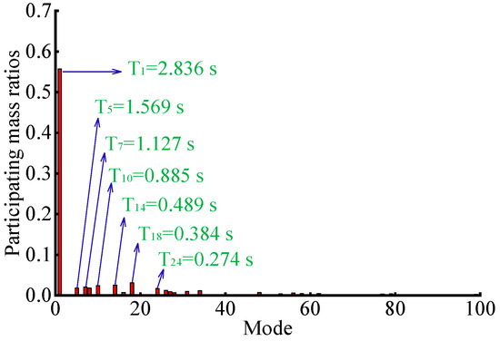
Figure 4.
Model participating mass ratios in longitudinal direction.
Table 2.
Typical longitudinal vibration shapes of piers.
For the movable piers P1 (46.3 m), P3 (85.5 m), P4 (61 m), and P5 (48.4 m), the fundamental longitudinal bending period increases with pier height, indicating that taller piers are relatively more flexible. For tall piers, particularly P2 and P3, the participating mass ratios of second-order longitudinal bending are still large, implying the easy occurrence of higher-order mode effects. The total cumulative participating mass ratios of all piers listed in Table 2 reach 69.7%, suggesting that the longitudinal seismic performance of the bridge is controlled by the model shapes of piers. Obviously, the dynamic characteristics and seismic behaviors of tall-pier girder bridges are quite different from the short- and medium-pier bridges. Therefore, the influence of higher-order modes should not be neglected in the seismic response analysis of tall-pier bridges.
3. Parametric Study of FVDs in Tall-Pier Girder Bridge
The symmetric hysteretic behavior of FVDs is mainly determined by the damping coefficient C and velocity exponent α. The damping coefficient C, relative velocity v between the piston and the cylinder, and the velocity exponent α jointly control the damping force. In this study, the damping coefficient C is varied between 200 and 1000 kN·(s/m)α, and the velocity exponent α is varied from 0.2 to 0.8, to find the optimal parameters for the FVDs in the tall-pier girder bridge. A total of 26 cases are considered for the parametric analysis. The primary function of FVDs is to enhance structural damping, providing both energy dissipation and displacement-limiting effects under strong earthquakes [20]. Thus, displacement responses are selected as the primary control indices, with internal force responses as secondary indicators. To assess the effectiveness of different FVD parameters, the seismic mitigating ratio is introduced and defined as Seismic Mitigating Ratio = (Response with FVD − Response without FVD)/Response without FVD.
3.1. Variations in Displacement Responses
Figure 5, Figure 6 and Figure 7 show the longitudinal displacement responses of the bearing, girder end, and pier top under earthquakes. In these figures, labels P1 to P5 correspond to the piers, while A0 and A6 represent the two abutments at each end.
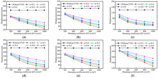
Figure 5.
Longitudinal displacement responses of bearing: (a) A0; (b) P1; (c) P3; (d) P4; (e) P5; (f) A6.
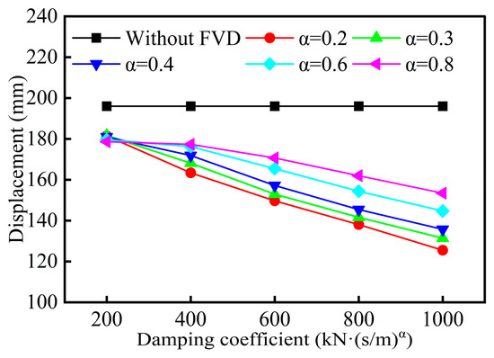
Figure 6.
Longitudinal displacement responses of girder end.
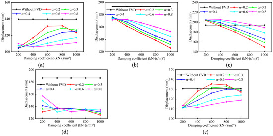
Figure 7.
Longitudinal displacement responses of pier top: (a) P1; (b) P2; (c) P3; (d) P4; (e) P5.
As shown in Figure 5 and Figure 6, FVDs effectively reduce the longitudinal displacements of the bearings and the girder end. When the velocity exponent α remains constant, the longitudinal displacements of the bearings and girder end decrease with increasing damping coefficient C. With a fixed damping coefficient C, the displacement responses of the bearings and girder end tend to increase as the velocity exponent α increases.
As shown in Figure 7, the longitudinal displacement responses of pier tops exhibit more complex variations for different pier heights. Under a fixed velocity exponent α, the top displacements of tall piers P2 and P3 decrease with increasing damping coefficient C. When the damping coefficient C remains constant, the top displacements of tall piers P2 and P3 increase with increasing velocity exponent α. It should be noted that the pier top displacements of P2 are all lower than the results from the models without FVDs (Figure 7b). However, pier top displacement of P3 could exceed the results when endowed with smaller damping coefficient C and larger velocity exponent α (Figure 7c). Conversely, the top displacements of tall piers P1 and P5 increase with increasing damping coefficient C, and decrease as velocity exponent α increases. Specifically, the pier top displacements exceed the results without FVDs when endowed with extreme small α and relatively large C (Figure 7e). For pier P4, the pier top displacements remain relatively stable (Figure 7d), within the range of C = 400 to 800, and all values are significantly smaller than the results without FVDs. Overall, the employment of FVDs can significantly reduce the longitudinal displacements of the bearings, girder ends, and pier tops.
3.2. Investigations into Internal Force Responses
To further investigate the influence of FVD parameters, the internal forces at the pier bottom are also selected as the evaluation index. Figure 8 and Figure 9 present the bottom shear force and bending moment responses of tall piers. Based on existing experimental results on hollow piers [32], the section for internal force output is chosen at the upper edge of the chamfer on the right leg of the hollow pier base.
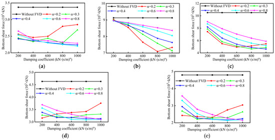
Figure 8.
Shear force responses of pier bottom: (a) P1; (b) P2; (c) P3; (d) P4; (e) P5.
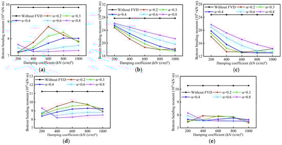
Figure 9.
Bending moment responses of pier bottom: (a) P1; (b) P2; (c) P3; (d) P4; (e) P5.
As shown in Figure 8, the bottom shear forces are all smaller than the results without FVDs, indicating their mitigating effect. For tall piers P2 and P3, the bottom shear forces decrease with increasing damping coefficient C, and increase with increasing velocity exponent α (except α = 0.2). For the remaining tall piers, the bottom shear forces decrease with increasing damping coefficient C when velocity exponent α ≥ 0.4. For α = 0.2 and 0.3, the bottom shear forces of most tall piers show a trend of decreasing first and then increasing, indicating that too small a velocity exponent α may intensify seismic responses.
Figure 9 reveals that the installation of FVDs effectively reduces the bottom bending moment responses of all piers. For tall piers P2 and P3, the bottom bending moment also decreases with increasing damping coefficient C, and increases with increasing velocity exponent α (except α = 0.2). For tall piers P1 and P4, the bottom bending moment slightly increases since the damping coefficient C exceeds 400 (except α = 0.2 and 0.3). For pier P5, the bottom bending moment remains relatively stable (Figure 9e). For too small or too large velocity exponent α, the variations of bottom bending moment exhibit a non-monotonic trend for most tall piers, which should be taken into consideration for parameter optimization.
Based on Figure 5, Figure 6, Figure 7, Figure 8 and Figure 9, it can be drawn that the FVDs can coordinate the force distribution among tall piers, and effectively reduce displacement responses and internal forces. Considering displacement, internal forces, and the FVD manufacturing, a velocity exponent α = 0.4 and a damping coefficient C = 600 kN·(s/m)α are recommended as the optimal FVD parameters for the selected asymmetric tall-pier girder bridge.
3.3. Seismic Mitigation Efficacy of the FVD
To further demonstrate the mitigation efficacy of the FVD in the tall-pier bridge, the simulations by analytical models with optimal FVDs and without FVDs are compared. Mitigating ratios of the bearing displacement and pier top displacement for all tall piers are shown in Table 3. The top displacement time histories of piers P2 and P3 with and without FVDs are compared in Figure 10. As can be observed, the maximum bearing displacements at piers P1, P3, P4, and P5 are 239.5 mm, 139.6 mm, 201.8 mm, and 230.3 mm, respectively. After the application of the optimal FVDs, these displacements are reduced to 102.1 mm, 48.9 mm, 69.6 mm, and 90.2 mm, respectively, resulting in mitigating ratios of −57.4%, −65.0%, −65.5%, and −60.8%. This quantitatively demonstrates that FVDs can significantly reduce the longitudinal bearing displacement responses for all piers, effectively preventing potential seismic damage such as girder collision or unseating. However, the mitigating ratios of the top displacement for piers P1 to P5 range from −3.0% to −26.8%, which are much lower than the displacement mitigation efficacy. In particular, the mitigating ratios of piers P3 and P5 are within −4%, which is attributed to the higher-order modes.
Table 3.
Mitigating ratios of bearing displacement and pier top displacement.
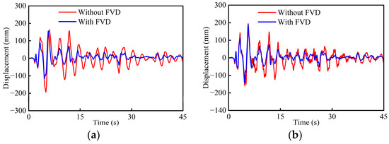
Figure 10.
Comparisons of pier top displacement time histories: (a) P2; (b) P3.
The hysteresis curves of the FVD and HDRB at movable pier P3 are shown in Figure 11. As seen, the hysteresis loops of the FVD are relatively full, whereas the corresponding hysteresis area of the HDRB is significantly smaller. This indicates that the FVDs effectively dissipate seismic energy and play a role in longitudinal displacement restriction.
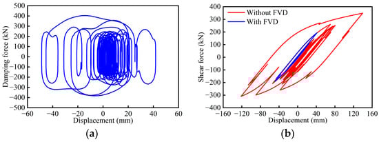
Figure 11.
Hysteresis curves: (a) FVD at P3; (b) HDRB at P3.
Mitigating ratios of the bottom internal force responses for all tall piers are shown in Table 4. The time histories of the bottom internal force of piers P2 and P3 with and without FVDs are compared in Figure 12 and Figure 13. The mitigating ratios of the shear force for movable piers ranges from −30.4% to −54.2% and those of the bending moment are from −17.9% to −46.4%, which demonstrates good mitigation efficacy. The discrepancy of mitigating ratios reveals that there is no linear relationship between displacement responses and internal forces like in bridges with medium-to-short piers. For fixed pier P2, the mitigating ratio of the shear force is only −8.8%, while that of bending moment is −25.3%. These phenomena can be attributed to the influence of higher-order modes. Overall, the optimal FVDs show promising seismic performance for tall-pier girder bridges due to their good capacities of energy dissipation and displacement restriction.
Table 4.
Mitigating ratios of shear force and bending moment.
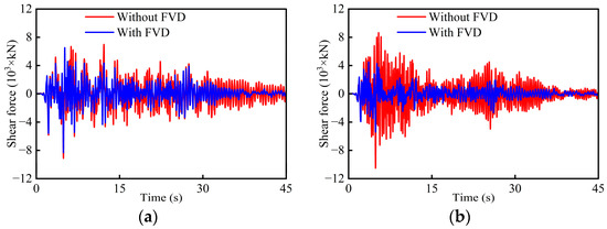
Figure 12.
Comparisons of bottom shear force time histories: (a) P2; (b) P3.
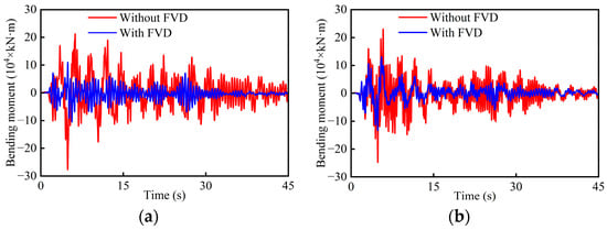
Figure 13.
Comparisons of bottom bending moment time histories: (a) P2; (b) P3.
4. Influence of Higher-Order Modes
This study indicates that tall-pier girder bridges generally exhibit greater flexibility and are more susceptible to the effects of higher-order modes, resulting in seismic behaviors different from those of conventional bridges [6]. Therefore, conducting systematic research on tall-pier bridges under earthquakes is of significant theoretical importance and provides valuable practical insights for engineering applications.
To explore the influence of higher-order modes, the tallest pier P2 is used as the reference, and the heights of the remaining piers are proportionally reduced as shown in Figure 14. By comparing the mode shapes and seismic responses of piers with different heights, the higher-order mode effects can be clearly reflected. Given that piers P2 and P3 are significantly taller than other piers, the model shapes, as well as displacement, shear force, and bending moment responses of P2 and P3, are selected for comparative analysis.
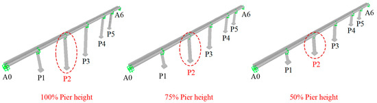
Figure 14.
Numerical models of bridges with different pier heights.
4.1. Model Shape Analysis
Comparisons of typical longitudinal mode periods of tall piers P2 and P3 are shown in Table 5. With the reduction in pier height, both the first-order longitudinal bending periods and the corresponding participating mass ratios of the fixed pier P2 exhibit a decreasing trend. In addition, when the pier height is reduced to 43.7 m, the first-order longitudinal bending mode of P2 changes from the first to the third mode, indicating an increase in longitudinal stiffness of the bridge. The second-order longitudinal bending mode of P2 initially appears at the 14th mode. As the pier height decreases, this mode is further delayed, appearing at higher mode numbers, while the corresponding periods decrease from 0.489 s to 0.125 s. For the movable pier P3, the first-order longitudinal bending periods decrease from 1.569 s to 0.696 s, while the participating mass ratios increase from 1.8% to 5.6%. However, both the second-order longitudinal bending periods and the corresponding participating mass ratios of the movable pier P3 exhibit a reduction. Notably, at all height levels, the longitudinal bending modes of P3 still exhibit relatively high participating mass ratios, ranging from 1.8% to 5.6%. These results suggest that tall piers are more susceptible to excite higher-order modes under earthquakes. The movable tall piers, in particular, are more prone to higher-order modes compared to the fixed tall piers.
Table 5.
Comparisons of typical longitudinal mode periods of piers P2 and P3.
4.2. Shear Force Envelopes
The shear force envelopes of tall piers P2 and P3 with and without FVDs are shown in Figure 15. For the fixed pier P2, the shear force envelopes generally exhibit a similar distribution for different heights, namely, larger shear forces at the pier ends and smaller values in the middle. The larger shear force at the pier top is mainly due to the longitudinal constraint between the top of pier P2 and the main girder, which causes most of the girder’s inertial force to be directly transferred to the upper part of the pier. The larger shear force at the bottom is attributed to the combined action of the pier and girder, corresponding primarily to the first-order longitudinal bending mode of the pier. Due to the higher-order mode effects—particularly the second-order longitudinal bending mode—the shear forces in the middle of the pier are smaller compared to its ends. As the pier height decreases, the contribution of higher-order modes diminishes. Though the mitigating ratio of 100%-height P2 at the bottom is only −8.8%, obvious reductions can be seen in shear forces along the pier body. Moreover, the shear forces of 75%-height P2 and 50%-height P2 with FVDs are much smaller than those without FVDs, indicating a good mitigation efficacy for the fixed tall piers.
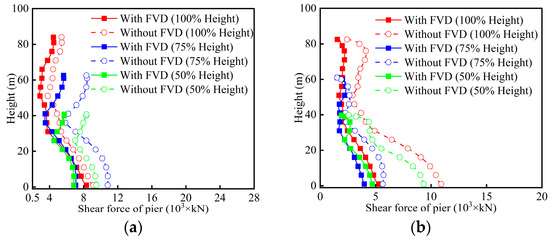
Figure 15.
Shear force envelopes: (a) P2; (b) P3.
For the movable pier P3, the shear force envelopes are more complex. The 85.5 m and 64.1 m piers show three inflection points, while the 42.8 m piers show two each. This is mainly because P3 is a movable pier with relatively weak constraints between the pier and girder, which allows more higher-order modes to be excited under earthquakes. These modes also have significant participating mass ratios, resulting in more irregular shear force distributions along the pier. Unlike P2, the installation of FVDs in P3 prominently reduces shear forces along the entire pier for 100%- and 50%-heights.
4.3. Bending Moment Envelopes
The bending moment envelopes of tall piers P2 and P3 with and without FVDs are shown in Figure 16. For the fixed pier P2, the bending moment envelope exhibits three inflection points for 100%- and 75%-heights. In addition, the bending moment in the bottom one-third region exhibits almost a linear distribution, while there is an obvious increase in the middle region due to higher-order mode effects. For 50%-height P2, however, the bending moment distribution approximately becomes linear, which agrees with the comment trend for medium-to-short piers [16]. Compared to models without FVDs, there is a significant reduction in bending moment within two-thirds of the pier height. Specially, a vertical straight-line bending moment distribution is found in the middle region of the 100%-height P2, revealing that the FVDs can improve the stress on the pier body.
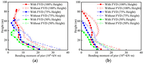
Figure 16.
Bending moment envelopes: (a) P2; (b) P3.
Due to the weaker constraint between the pier and the girder, the bending moment envelopes of movable pier P3 are different from the fixed pier P2. There is an S-shaped distribution of bending moment for 100%-height P3 especially due to the second-order mode shapes. Consequently, at approximately 40 m of the pier, the bending moments are 11.5 × 10⁴ kN·m and 6.7 × 10⁴ kN·m, respectively, which are 47.8% and 17.9% greater than the corresponding values at the 20 m position. The large bending moment at the middle region of the non-FVD tall piers implies that a second plastic hinge may form, in addition to the traditional plastic hinge at the pier bottom. However, both bottom and middle bending moment of 100%-height P3 are reduced by the FVDs, indicating that the FVDs can weaken the influence of higher-order modes. As the height decrease, the bending moment envelopes of 75%- and 50%-height P3 tend to be a linear distribution, implying the reduced higher-order mode effects. Therefore, in seismic evaluation, in addition to the pier bottom, attention should also be paid to the mid-height region of tall piers.
5. Influence of Near-Field Earthquakes
Given that tall-pier girder bridges located in mountainous regions are often near active faults and their long structure’s fundamental natural period is sensitive to long-period velocity pulse, the influence of near-field earthquakes is investigated in this section. Four near-field ground motions recorded during the Chi-Chi earthquake are selected for this study, as shown in Table 6. The acceleration time histories and response spectra of the selected near-field earthquakes are shown in Figure 17. The natural vibration period of the tall-pier girder bridge in the longitudinal direction is 2.836 s. Therefore, RSN2734 is termed a medium-period record because its pulse period (Tp = 2.436 s) is close to the longitudinal period of the tall-pier bridge. Correspondingly, RSN2495 represents a short-period record (Tp = 1.379 s) and RSN1244 a long-period record (Tp = 5.341 s). For comparison, the non-pulse record RSN1513 is also considered.
Table 6.
Basic information of the selected near-field earthquakes.
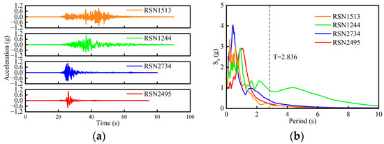
Figure 17.
Acceleration time histories (a) and response spectra (b) of the near-field earthquakes.
5.1. Comparisons of Displacement
The displacement envelopes of piers P2 and P3 are shown in Figure 18 and Figure 19. As seen in Figure 18, the maximum displacements occur under long-period pulse-like motion, highlighting the slender tall-pier bridge’s sensitivity to high spectral accelerations at medium-to-long periods. Significant displacements also engender under medium-period pulse-like motion, primarily due to resonance arising from the close match between the bridge’s fundamental structural period (2.863 s) and the pulse period (2.436 s). The short-period pulse-like motion results in relatively small displacement response since its pulse period with regard to spectral amplification is far away from the fundamental structural period. The non-pulse motion produces the smallest displacement response, though its spectral values around the fundamental structural period are close to the short-period pulse-like motion (Figure 17b). As seen in Figure 19, a similar trend is observed in pier P3. Overall, the displacements of piers with different heights can be effectively reduced. For 100%-height P2 and P3, the best mitigating efficacy exhibits under long-period pulse-like motion (Figure 18c and Figure 19c). For 100%- and 75%-height P2 under short-period pulse-like motion, the displacement responses with and without FVDs are almost the same (Figure 18a). This may be attributed to the fact that the FVD is insensitive to high-frequency components together with the influence of higher-order modes.
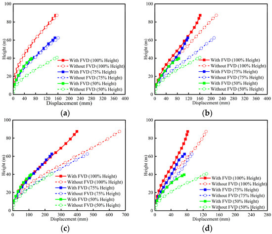
Figure 18.
Displacement envelopes of P2: (a) RSN2495 (short-period); (b) RSN2734 (medium-period); (c) RSN1244 (long-period); (d) RSN1513 (non-pulse).
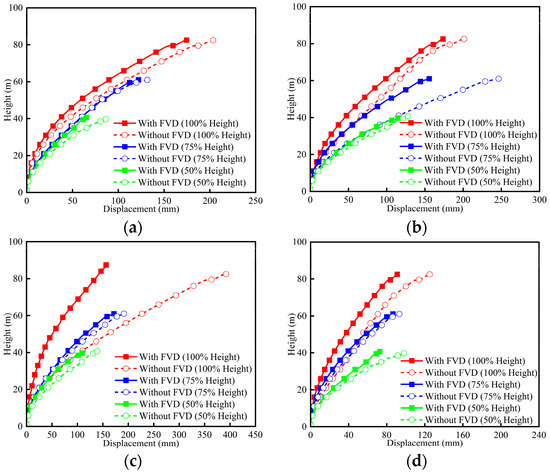
Figure 19.
Displacement envelopes of P3: (a) RSN2495 (short-period); (b) RSN2734 (medium-period); (c) RSN1244 (long-period); (d) RSN1513 (non-pulse).
5.2. Comparisons of Shear Force
The shear force envelopes of piers P2 and P3 are shown in Figure 20 and Figure 21. As shown in Figure 20, larger shear forces at the pier ends and smaller values in the middle are observed in 100%-height P2 due to the rigid constraint between the pier top and girder. The concave points of 100%-height P2 are different under four types of near-field earthquakes, implying the higher-order modes excited may differ as the pulse period changes. As height decreases, the shear force envelopes from the pier bottom to concave point tend to be linear, implying weakened higher-order mode effects. When endowed with FVDs, the shear force responses of 100%-height P2 are greatly reduced. By comparing Figure 18a and Figure 20a, the shear force of 100%-height P2 within 40 m is obviously reduced though the displacements envelopes are almost similar. This further demonstrates that there is no direct relationship between displacement and shear force responses for tall piers. Note that 75%-height P2 and 50%-height P2 yield even larger displacements than the 100%-height P2, which may be due to the non-optimal FVD parameter for bridges with reduced heights.
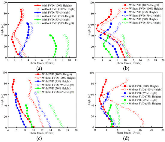
Figure 20.
Shear force envelopes of P2: (a) RSN2495 (short-period); (b) RSN2734 (medium-period); (c) RSN1244 (long-period); (d) RSN1513 (non-pulse).
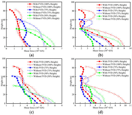
Figure 21.
Shear force envelopes of P3: (a) RSN2495 (short-period); (b) RSN2734 (medium-period); (c) RSN1244 (long-period); (d) RSN1513 (non-pulse).
As shown in Figure 21, the shear force envelopes of the movable pier P3 exhibit more complex distributions. Under medium-period pulse-like motion and non-pulse motion, there are significantly obvious S-shaped distributions for 100%-height P3, and the smallest shear force occurs at 50 m. Under short-period pulse-like motion, weakened S-shaped shear force distributions are observed in 100%-height P3. Under long-period pulse-like motion, the shear force distributions of 100%-height P3 tend to be approximately linear. As pier heights decrease, the shear force envelopes under four types of near-field motions also approach more linear distribution, reflecting the reduced higher-order mode effects. Overall, the influence of higher-order modes on piers with three heights under different near-field earthquakes is different. By combining Figure 17b and Figure 21, it can be drawn that the higher-order modes are easily excited by the motions with large spectral values in high-frequency range. The use of FVDs not only reduces the shear force responses of tall piers, but also weakens the influence of higher-order modes.
5.3. Comparisons of Bending Moment
The bending moment envelopes of piers P2 and P3 are shown in Figure 22 and Figure 23. As shown in Figure 22, approximate bilinear distributions are observed in the bending moment envelopes under short-period and long-period pulse-like motions, especially for 75%-height P2 and 50%-height P2. However, there are obvious convex-concave in the bending moment envelopes under medium-period pulse-like and non-pulse motions for 100%-height P2 and 75%-height P2. Reducing the height of P2 to half of its original level, the bending moment envelopes become linear since the 50%-height P3 is mainly controlled by the first-order model shape. The maximum bending moment responses of P2 occur under long-period pulse-like motion, confirming the spectral amplification at medium-to-long periods. Overall, the implementation of FVDs can greatly reduce the bending moment along the pier, especially at the pier bottom. However, the bending moment envelopes of 100%- and 75%-height P2 with FVDs under short-period pulse-like motion are close to the results without FVDs (Figure 22a), which is consistent with the displacement responses (Figure 18a) due to the same reason.
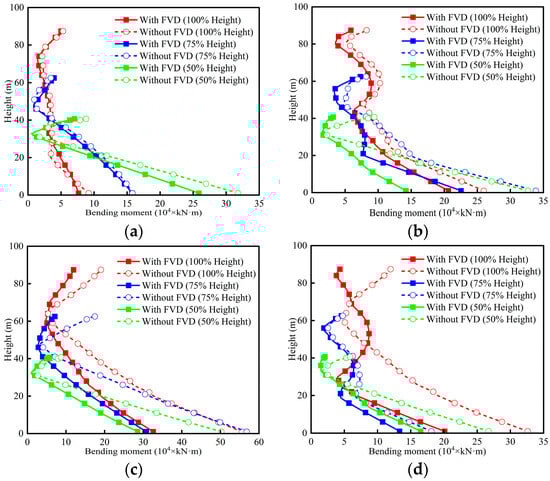
Figure 22.
Bending moment envelopes of P2: (a) RSN2495 (short-period); (b) RSN2734 (medium-period); (c) RSN1244 (long-period); (d) RSN1513 (non-pulse).
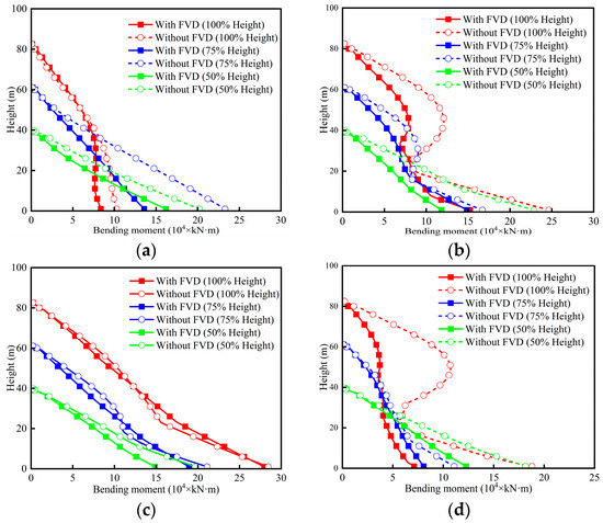
Figure 23.
Bending moment envelopes of P3: (a) RSN2495 (short-period); (b) RSN2734 (medium-period); (c) RSN1244 (long-period); (d) RSN1513 (non-pulse).
As shown in Figure 23, there are obvious S-shaped bending moment distributions for 100%-height P3 under medium-period pulse-like and non-pulse motions. Under short-period pulse-like motion, slight S-shaped bending moment envelopes are observed in 100%-height P3. Under long-period pulse-like motion, the bending moment envelopes of 100%-height P3 tend to be linear. This confirms the fact that the higher-order modes are easier to excite by the motions with large spectral values in high-frequency range. Again, the maximum bending moment responses of P3 occur under long-period pulse-like motion. Like in shear force, the bending moment envelopes of pier P3 under four types of near-field motions tend to be a linear distribution with decreasing height, due to the weakness of higher-order mode effects. In addition, the FVDs can simultaneously reduce the bending moment responses of tall piers and suppress the higher-order mode effects.
6. Conclusions
This study focuses on the longitudinal seismic performance of asymmetric tall-pier girder bridges using FVDs. Numerical simulations are performed to optimize the FVD parameters and clarify the higher-order mode effects. The influence of near-field earthquakes on the FVD and higher-order modes is also explored. Key findings are as follows.
(1) In tall-pier girder bridges, higher-order modes of tall piers have large participating mass ratios and may be activated simultaneously under strong earthquakes. As the pier height decreases, the longitudinal bending mode of tall piers will be progressively delayed, implying the higher-order modes are becoming difficult to excite.
(2) When equipped with optimal FVDs (velocity exponent α = 0.4 and damping coefficient C = 600 kN·(s/m)α), the forces among asymmetrically arranged tall piers are coordinated, and displacement responses and internal forces are effectively reduced.
(3) The concave-convex or S-shaped distributions are observed in shear force and bending moment envelopes of original tall piers. In particular, the large bending moment at the middle region will lead to a second plastic hinge, in addition to the traditional plastic hinge at the pier bottom. As pier heights decrease, the internal force envelopes gradually become linear, implying the higher-order mode effects are gradually diminished.
(4) Owing to the slender tall-pier bridge’s susceptibility to medium-to-long period spectral accelerations, long-period pulse-like motions generate the maximum seismic responses. Furthermore, near-field motions exhibiting large spectral values in the high-frequency range efficiently excite higher-order modes. Crucially, FVDs can concurrently suppress seismic responses in the tall piers and lessen the impact of higher-order modes.
Future research will focus on the FVD mitigation behavior of tall-pier girder bridges under different PGA levels. Moreover, the influence of pulse characteristics on the seismic performance of FVD-equipped tall-pier girder bridges should be investigated by more near-field ground motions.
Author Contributions
Conceptualization, Q.Q.; methodology, H.Y. and W.G.; software, H.Y.; validation, H.Y., C.S. and H.C.; investigation, Z.P. and J.H.; data curation, J.H., W.G. and H.C.; writing—original draft preparation, Z.P.; writing—review and editing, Q.Q.; supervision, C.S.; funding acquisition, Q.Q. and C.S. All authors have read and agreed to the published version of the manuscript.
Funding
This research was funded by the National Key R&D Program of China [No. 2023YFB2604402], the National Natural Science Foundation of China [No. 51978581], and the Sichuan Science and Technology Program [No. 2025ZNSFSC1315].
Data Availability Statement
Data is contained within the article.
Conflicts of Interest
The authors declare no conflict of interest.
References
- Guo, W.; Li, J.; Guan, Z. Shake table test on a long-span cable-stayed bridge with viscous dampers considering wave passage effects. J. Bridge Eng. 2021, 26, 04020118. [Google Scholar] [CrossRef]
- Chen, X.; Ding, H.; Li, C. A quasi-tuned-mass-damper design concept for mitigating the dynamic displacement demand of tall piers. Soil Dyn. Earthq. Eng. 2022, 155, 107172. [Google Scholar] [CrossRef]
- Li, J.; Peng, T.; Xu, Y. Damage investigation of girder bridges under the Wenchuan earthquake and corresponding seismic design recommendations. Earthq. Eng. Eng. Vib. 2008, 7, 337–344. [Google Scholar] [CrossRef]
- Liu, J.; Fan, Y.; Shi, P. Response to a high-altitude earthquake: The Yushu Earthquake example. Int. J. Disaster Risk Sci. 2011, 2, 43–53. [Google Scholar] [CrossRef]
- Xu, X.; Wen, X.; Han, Z.; Chen, G.; Li, C.; Zheng, W.; Zhang, S.; Ren, Z.; Xu, C.; Tan, X. Lushan Ms 7.0 earthquake: A blind reserve-fault event. Chin. Sci. Bull. 2013, 58, 3437–3443. [Google Scholar] [CrossRef]
- Qi, Q.; Shao, C.; Wei, W.; Xiao, Z.; He, J. Seismic performance of railway rounded rectangular hollow tall piers using the shaking table test. Eng. Struct. 2020, 220, 110968. [Google Scholar] [CrossRef]
- Shang, J.; Tan, P.; Zhang, Y.; Han, J.; Mi, P. Seismic isolation design of structure using variable friction pendulum bearings. Soil Dyn. Earthq. Eng. 2021, 148, 106855. [Google Scholar] [CrossRef]
- Wei, B.; Yang, Z.; Fu, Y.; Xiao, B.; Jiang, L. Seismic displacement response analysis of Friction Pendulum Bearing under friction coupling and collision effects. Eng. Struct. 2024, 310, 118128. [Google Scholar] [CrossRef]
- Zheng, W.; Tan, P.; Li, J.; Wang, H.; Liu, Y.; Xian, Z. Superelastic conical friction pendulum isolator for seismic isolation of bridges under near-fault ground motions. Struct. Control Health Monit. 2023, 2023, 5497731. [Google Scholar] [CrossRef]
- Aghaeidoost, V.; Billah, A.M. An advanced rate-dependent analytical model of lead rubber bearing. Earthq. Eng. Struct. Dyn. 2024, 53, 1961–1981. [Google Scholar] [CrossRef]
- Chen, P.; Wang, B.; Zhang, Z.; Li, T.; Dai, K. A generalized model of lead rubber bearing considering large strain stiffening and degradation. Eng. Struct. 2023, 275, 115264. [Google Scholar] [CrossRef]
- Chen, X.; Wu, S.; Li, J.; Guan, Z.; Xiang, N. Seismic performance assessment and design procedure of base-isolated bridges with lead-rubber-bearing and negative stiffness springs (LRB-NS). Eng. Struct. 2024, 306, 117871. [Google Scholar] [CrossRef]
- Gu, H.; Itoh, Y. Ageing behaviour of natural rubber and high damping rubber materials used in bridge rubber bearings. Adv. Struct. Eng. 2010, 13, 1105–1113. [Google Scholar] [CrossRef]
- Tubaldi, E.; Mitoulis, S.A.; Ahmadi, H. Comparison of different models for high damping rubber bearings in seismically isolated bridges. Soil Dyn. Earthq. Eng. 2018, 104, 329–345. [Google Scholar] [CrossRef]
- Qi, Q.; Shao, C.; Cui, H.; Huang, H.; Wei, W.; Wang, C.; Zhuang, W. Shaking table tests and numerical studies on the seismic behaviors of FPB in railway continuous beam bridges. Eng. Struct. 2023, 290, 116318. [Google Scholar] [CrossRef]
- Su, L.; Zhang, W.; Chen, Y.; Zhang, C. Seismic design and shaking table test of continuous girder bridges with winding rope fluid viscous dampers. Eng. Struct. 2023, 277, 115408. [Google Scholar] [CrossRef]
- Guo, J.; Li, M.; Wu, Y.; Xiao, Y.; Guan, Z. Experimental study on a cable-stayed bridge isolated with the combination of elastoplastic cables and fluid viscous dampers in the transverse direction. Eng. Struct. 2024, 302, 117447. [Google Scholar] [CrossRef]
- Wang, Q.; Zheng, Z.; Qiao, H.; De Domenico, D. Seismic protection of reinforced concrete continuous girder bridges with inerter-based vibration absorbers. Soil Dyn. Earthq. Eng. 2023, 164, 107526. [Google Scholar] [CrossRef]
- Liu, Q.; Zhu, S.; Yu, W.; Wu, X.; Song, F.; Ren, X. Ground motion frequency insensitivity of bearing-supported pedestrian bridge with viscous dampers. KSCE J. Civ. Eng. 2021, 25, 2662–2673. [Google Scholar] [CrossRef]
- Zhong, J.; Hu, Z.; Yuan, W.; Chen, L. System-based probabilistic optimization of fluid viscous dampers equipped in cable-stayed bridges. Adv. Struct. Eng. 2018, 21, 1815–1825. [Google Scholar] [CrossRef]
- Liang, X.; Li, B.; Liu, X.; Liang, L. Optimisation of longitudinal seismic energy dissipation system for straddle-type monorail-cum-road long-span cable-stayed bridge. Shock Vib. 2019, 2019, 9637356. [Google Scholar] [CrossRef]
- Jing, H.; Feng, Z.; Chen, Z.; Hua, X.; Chen, Z.; Wan, T. Enhancing longitudinal performance in railway suspension bridges through an integrated cable restrainer system. Structures 2024, 65, 106769. [Google Scholar] [CrossRef]
- Bas, S.; Dong, C.Z.; Apaydin, N.M.; Ilki, A.; Catbas, F.N. Hanger replacement influence on seismic response of suspension bridges: Implementation to the Bosphorus Bridge subjected to multi-support excitation. Earthq. Eng. Struct. Dyn. 2020, 49, 1496–1518. [Google Scholar] [CrossRef]
- Chen, X.; Spencer, B.F., Jr.; Li, J.; Guan, Z.; Pang, Y. Optimization of distribution patterns of link beams in a double-column tall pier bent subjected to earthquake excitations. Earthq. Eng. Struct. Dyn. 2023, 52, 641–659. [Google Scholar] [CrossRef]
- Chen, X.; Xiang, N.; Guan, Z.; Li, J. Seismic vulnerability assessment of tall pier bridges under mainshock-aftershock-like earthquake sequences using vector-valued intensity measure. Eng. Struct. 2022, 253, 113732. [Google Scholar] [CrossRef]
- Guan, Z.; Li, J.; Xu, Y.; Lu, H. Higher-order mode effects on the seismic performance of tall piers. Front. Struct. Civ. Eng. 2011, 5, 496–502. [Google Scholar] [CrossRef]
- Chen, X.; Wu, P.; Li, C. Seismic performance assessment of base-isolated tall pier bridges using friction pendulum bearings achieving resilient design. Structures 2022, 38, 618–629. [Google Scholar] [CrossRef]
- Makris, N.; Constantinou, M. Fractional-derivative maxwell model for viscous dampers. J. Struct. Eng. 1991, 117, 2708–2724. [Google Scholar] [CrossRef]
- JT/T 842-2012; High Damping Seismic Isolation Rubber Bearings for Highway Bridges. Ministry of Transport of the People’s Republic of China: Beijing, China, 2012.
- JTG/T 2231-01-2020; Specifications for Seismic Design of Highway Bridges. Ministry of Transport of the People’s Republic of China: Beijing, China, 2020.
- JTG 3363-2019; Specifications for Design of Foundation of Highway Bridges and Culverts. Ministry of Transport of the People’s Republic of China: Beijing, China, 2019.
- Qi, Q.; Shao, C.; Yang, H.; Cui, H.; Chen, Z.; Gong, W. Axial-flexure-shear model for seismic analysis of RC thin-walled hollow piers. Soil Dyn. Earthq. Eng. 2025, 195, 109375. [Google Scholar] [CrossRef]
Disclaimer/Publisher’s Note: The statements, opinions and data contained in all publications are solely those of the individual author(s) and contributor(s) and not of MDPI and/or the editor(s). MDPI and/or the editor(s) disclaim responsibility for any injury to people or property resulting from any ideas, methods, instructions or products referred to in the content. |
© 2025 by the authors. Licensee MDPI, Basel, Switzerland. This article is an open access article distributed under the terms and conditions of the Creative Commons Attribution (CC BY) license (https://creativecommons.org/licenses/by/4.0/).