Article

A CML-ECA Chaotic Image Encryption System Based on Multi-Source Perturbation Mechanism and Dynamic DNA Encoding

1
School of Information Science and Technology, Hainan Normal University, Haikou 571158, China
2
Hainan Engineering Research Center for Virtual Reality Technology and Systems, Hainan Vocational University of Science and Technology, Haikou 571126, China
3
Faculty of Arts and Science, University of Toronto, Toronto, ON M5S 1A1, Canada
*
Authors to whom correspondence should be addressed.
Symmetry 2025, 17(7), 1042; https://doi.org/10.3390/sym17071042
Submission received: 17 May 2025 / Revised: 22 June 2025 / Accepted: 25 June 2025 / Published: 2 July 2025
(This article belongs to the Section Computer)

Abstract

To meet the growing demand for secure and reliable image protection in digital communication, this paper proposes a novel image encryption framework that addresses the challenges of high plaintext sensitivity, resistance to statistical attacks, and key security. The method combines a two-dimensional dynamically coupled map lattice (2D DCML) with elementary cellular automata (ECA) to construct a heterogeneous chaotic system with strong spatiotemporal complexity. To further enhance nonlinearity and diffusion, a multi-source perturbation mechanism and adaptive DNA encoding strategy are introduced. These components work together to obscure the image structure, pixel correlations, and histogram characteristics. By embedding spatial and temporal symmetry into the coupled lattice evolution and perturbation processes, the proposed method ensures a more uniform and balanced transformation of image data. Meanwhile, the method enhances the confusion and diffusion effects by utilizing the principle of symmetric perturbation, thereby improving the overall security of the system. Experimental evaluations on standard images demonstrate that the proposed scheme achieves high encryption quality in terms of histogram uniformity, information entropy, NPCR, UACI, and key sensitivity tests. It also shows strong resistance to chosen plaintext attacks, confirming its robustness for secure image transmission.

1. Introduction

With the widespread application of digital images in fields such as medical diagnosis, intelligent surveillance, cloud computing, and unmanned systems, ensuring the security of image information has become a growing concern. Unlike conventional text data, image data typically exhibit high redundancy, strong spatial correlation, and large volume, making them less compatible with traditional encryption algorithms, like AES and DES. These classical schemes often struggle to meet the demands of real-time and high-security requirements due to their rigid structure and computational inefficiency. As a result, the development of efficient, highly secure, and structurally adaptive image encryption methods has emerged as a focal point in the field of information security research.
In recent years, chaotic systems have drawn considerable attention in the fields of image encryption and secure communication due to their sensitivity to initial conditions, ergodicity, and nonlinear dynamical properties. Qobbi Yet al. [1,2] proposed an image encryption algorithm that combines genetic operations with chaotic DNA encoding, which has effectively enhanced the security of encrypted images and their resistance to statistical attacks. In 2023, researchers also designed an image encryption method based on dynamic permutation and a large-scale chaotic S-box, aiming to strengthen the confusion and diffusion properties of the encryption system to resist differential attacks. In recent years, the integration of chaotic systems into image encryption has garnered widespread attention due to their intrinsic properties, such as initial condition sensitivity, ergodicity, and nonlinear dynamics. Chai’s team [3] proposed a chaos-based encryption algorithm leveraging DNA sequence operations, which enhanced both the complexity and security of encryption. Hua et al. [4] introduced an encryption method that utilizes value-difference transformation and an improved zigzag scan to boost efficiency and resistance against attacks. Niyat [5] presented a scheme combining cellular automata and DNA sequences within a chaotic framework, significantly increasing encryption diversity and robustness. Kaslik et al. [6] explored nonlinear dynamics and chaos in fractional-order neural networks, offering theoretical support for analyzing chaotic behaviors in such models. Iqbal et al. [7] proposed a novel fractional-order three-dimensional chaotic system applied to secure communication via chaotic synchronization. Wu J [8] introduced a compact encryption scheme based on the Arnold transform, achieving high encryption and decryption efficiency. Bettayeb’s team [9] proposed a single-channel secure communication protocol based on a fractional-order chaotic Chua system, improving communication confidentiality. Agrawal and Srivastava M [10] investigated active control techniques for synchronizing fractional-order chaotic systems, providing new avenues for system control. Iqbal et al. [11] proposed a color image encryption approach based on DNA strand-level perturbation, increasing complexity and resistance to attacks. Kumar et al. [12] introduced a novel RGB image encryption method using a generalized Vigenère table and a virtual planetary domain to enhance security. Zhuang’s team [13] proposed a medical image encryption algorithm based on a novel five-dimensional multiband multi-wing chaotic system and QR decomposition, significantly strengthening medical data confidentiality. Zhao et al. [14] developed a fast encryption algorithm using a multi-parameter fractal matrix and an MPMCML system, which improved encryption speed and efficiency. Niu and Zhou Z [15] presented an encryption approach combining chaotic maps with genetic operations, enhancing both encryption diversity and complexity. Benaissi et al. [16] proposed an innovative scheme using hybrid chaotic maps and a key image, improving security and attack resistance. Zou et al. [17] developed a novel algorithm resistant to tampering attacks, enhancing cipher robustness. Cao’s team [18] designed a two-dimensional infinite collapse map for image encryption, achieving both efficiency and security. Wang and Liu P [19] proposed a new fully chaotic coupled map lattice applied to privacy-preserving image encryption, increasing encryption complexity and confidentiality. Long et al. [20] developed an improved fractal coding system combined with a hyperchaotic generator for lossless image compression and encryption, boosting overall performance. Meng [21] introduced a color image encryption/decryption scheme using extended DNA coding and a fractional-order five-dimensional hyperchaotic system, enhancing both security and complexity. Yan’s team [22] presented an encryption technique for unmanned vehicle images based on a novel four-wing three-dimensional chaotic system and compressive sensing, improving both efficiency and attack resilience. Wang et al. [23] developed a two-dimensional cross hyperchaotic sine-modulated logistic map for bit-level encryption, significantly enhancing security diversity. Jackson [24] introduced an image encryption strategy using a novel 2D hyperchaotic sine-logistic map, aimed at optimizing both efficiency and robustness. Zhou et al. [25] proposed a multi-image encryption scheme that combines a four-dimensional chaotic system with multilayer embedding, reinforcing encryption security and complexity. Wang et al. [26] presented an approach combining bit-plane cross-diffusion with a spatiotemporal chaotic system under nonlinear perturbation, offering improved performance and resistance to attacks. Teng’s group [27] introduced a color image encryption algorithm based on a cross 2D hyperchaotic map, using combined circular shift perturbations and selective diffusion to boost security. Ma et al. [28] proposed an encryption system using a 4D discrete Hopfield neural network featuring multiple diffusion strategies, increasing flexibility and security. Zhou [29] developed a novel multi-image encryption algorithm based on a 2D hyperchaotic modular model, improving efficiency and robustness for simultaneous image encryption. Li et al. [30] presented a color image encryption method that incorporates an enhanced dual-chaotic system and DNA encoding, strengthening both encryption complexity and reliability. In addition, several studies have explored the integration of high-dimensional chaotic systems with perturbation structures for more effective image encryption. Wu XG et al. [31] designed a lossless color image encryption system combining DNA encryption with entropy optimization, leveraging chaotic maps for performance gains. Wu X et al. [32] introduced a DNA-based encryption method using NCA mapping and one-time keys, reinforcing both security and resilience. Suri’s team [33] proposed a synchronized interleaved logic mapping and DNA-based approach for color image encryption, significantly enhancing encryption speed and security. Although the above-mentioned schemes demonstrate diversity and innovation in the field of image encryption, they still face practical challenges, such as high computational complexity and difficulties in key management. While chaotic systems offer powerful capabilities, their extreme sensitivity to initial conditions can easily lead to instability during the encryption process. Moreover, the boundedness and limited ergodicity of chaotic systems may reduce randomness, resulting in pattern repetition and weakened encryption security. Traditional two-dimensional coupled map lattice (2D CML) systems continue to encounter issues, such as structural rigidity, limited perturbation mechanisms, and poor dynamic adaptability in image encryption applications.
To address the aforementioned issues, this paper proposes a two-dimensional chaotic system based on cellular automaton-driven perturbation, dynamic coupling mechanisms, and the integration of nonlinear masking perturbations. This system is embedded into a color image encryption framework, achieving multi-channel asynchronous perturbation and providing high-security image protection.
The main innovative contributions of this study are as follows:
(1) A new ECA structure is proposed, combining 1D temporal perturbation with 2D spatial coupling. In this structure, the ECA maintains the 1D linear update rule (such as Rule 30, 105, etc.), but spatial mapping is carried out through a two-dimensional Arnold cat map, generating a dynamic 2D perturbation matrix. This matrix then controls the perturbation paths and coupling target selection of each point in the 2D CML.
(2) To address the issue of fixed and unidirectional coupling range in traditional 2D CML systems, a dynamic coupling coordinate selection mechanism is introduced. Based on the location of the mapped point (x’, y’) in the 2D spatial map, the coupling direction in the 2D CML is dynamically determined. Furthermore, the coupling strength is jointly controlled by the base parameters and the nonlinear perturbation terms driven by the ECA, allowing dynamic adjustability and spatial nonuniformity of the coupling weights at each grid point.
(3) Based on the dynamic 2D perturbation matrix, the cross values for perturbation are obtained through two iterations of the Arnold cat map. These values are then XORed with dynamic masks generated by various chaotic mappings and random noise, resulting in the final perturbation values. The perturbation generated in this manner significantly enhances the nonlinear complexity and local sensitivity of the chaotic system, ensuring that the perturbation of each pixel exhibits low correlation and high entropy.
The remainder of this paper is organized as follows. Section 2 provides a detailed description of elementary cellular automata and traditional 2D CML systems. Section 3 focuses on the proposed chaotic system, its performance, and a comparison with other systems. Section 4 describes the proposed image encryption scheme. Simulation results and performance analysis are presented in Section 5.

2. Related Work

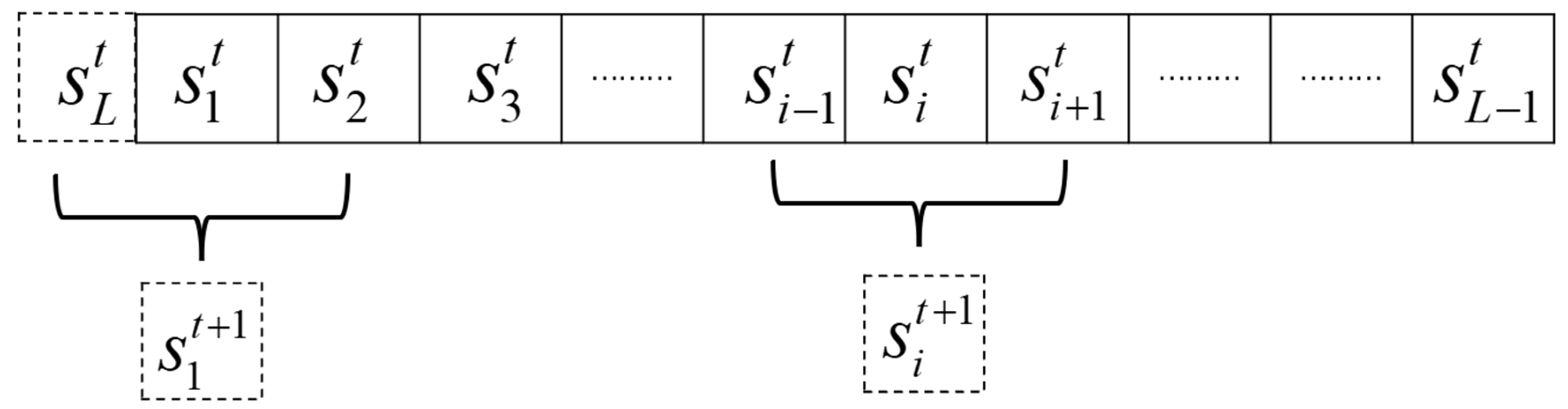
2.1. Elementary Cellular Automata (ECA)

Elementary cellular automata (ECA) is a dynamic model based on discrete spatiotemporal evolution, where complex global behaviors are generated through the synchronous iteration of local rules on a one-dimensional discrete grid. Each cell has only two possible states (0 or 1), and its next state is determined by its own state and the current states of its two neighboring cells on the left and right, as shown in Figure 1. Mathematically, this can be represented as follows:
s i t + 1 = f ( s i 1 t , s i t , s i + 1 t ) , s i t { 0 , 1 }
In this equation, t (where t = 1,2,3…) represents the time index, and i (where i = 1, 2, 3, …, L) represents the position index of each cell. s i t denotes the state of the i -th cell at time t , and f : { 0 , 1 } 3 { 0 , 1 } is the local update rule, corresponding to one of the 256 ECA rules proposed by Wolfram. Table 1, Table 2 and Table 3 display the representative rules, Rule 60, Rule 105, and Rule 150, respectively.
Moreover, the total number of cells L in the ECA system should be equal to the total number of cells in the 2D coupled map lattice (CML), L = N 2 where N is the grid size. This ensures that each cell in the CML corresponds to a unique cell index in the ECA system during the mapping process.

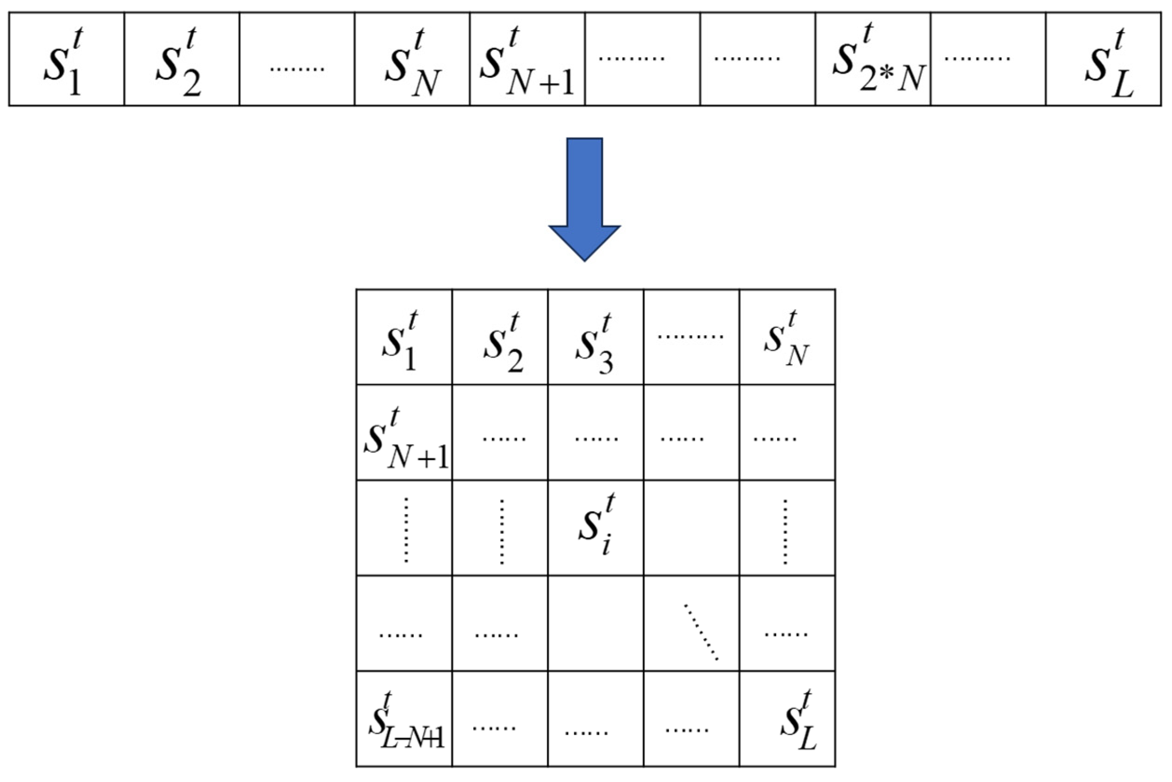
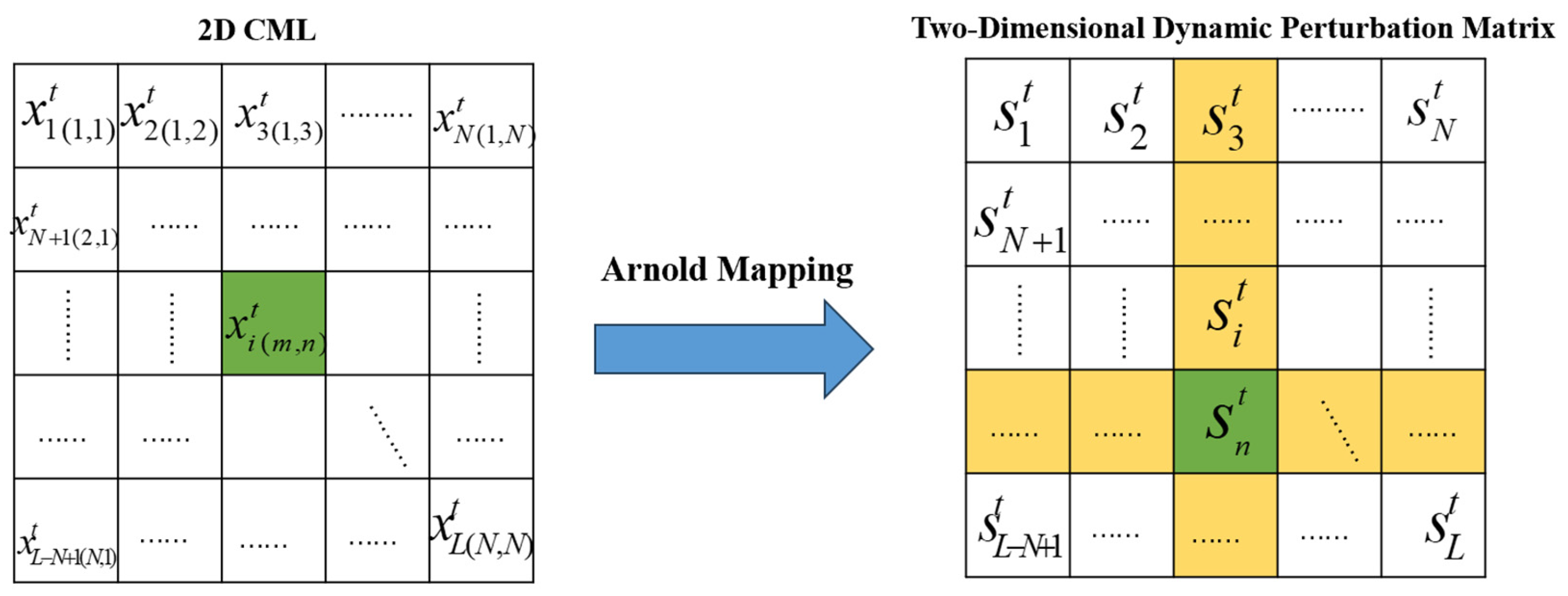
2.2. Two-Dimensional Coupled Map Lattice (2D CML)

The two-dimensional coupled map lattice (2D CML) is an important discrete model for studying complex spatiotemporal dynamical behaviors. It consists of a two-dimensional grid, where each grid point represents a spatiotemporal unit. The state evolution of each grid point depends on local nonlinear mappings and the coupling interactions with neighboring grid points, forming a spatiotemporal coupled dynamical system. In a 2D CML, each grid point is influenced by its four neighboring points, and the system can be defined as follows:
x n + 1 ( i , j ) = ( 1 ε ) f [ x n ( i , j ) ] + ε 4 { f [ x n ( i + 1 , j ) ] + f [ x n ( i 1 , j ) ] + f [ x n ( i , j + 1 ) ] + f [ x n ( i , j 1 ) ] }
In the equation, ε represents the coupling strength, which is used to adjust the balance between the influence of the local mapping dynamics and the spatial interactions between neighboring grid points. f ( ) is the local nonlinear mapping.

3. The Chaotic System Proposed in This Paper

3.1. Introduction to the Proposed System

The system proposed in this paper is a two-dimensional coupled map lattice (2D CML) system that integrates dynamic perturbation mechanisms, cellular automata evolution structures, and Arnold map scheduling mechanisms. It is defined as follows:
x i j t + 1 = ( 1 ε i j t ) f ( x i j t ) + ε i j t 4 N i j ( t ) N i j ( t ) = k = 1 4 ( 1 ) E C A m k n k ( t ) λ k ( x m k n k ( t ) )
Here, x i j t represents the state value of grid point ( i , j ) at time t . Its evolution is determined by both the self-mapping and coupling terms. In this chaotic system, the self-mapping term uses the logistic map f ( x ) = μ x ( 1 x ) to control the chaotic updates of each grid point. The coupling term adjusts the coupling ratio between a grid point and its neighborhood through the dynamic coupling strength ε i j t , which varies with the cellular automaton state.
The coupling perturbation term N i j ( t ) integrates nonlinear perturbations from neighbors in four directions. x m k n k ( t ) indicates the state value at the k -th neighbor position ( m k , n k ) at time t . Four mapping functions λ 1 ( x ) = x , λ 2 ( x ) = x 3 , λ 3 ( x ) = tanh ( 5 x ) , and λ 4 ( x ) = x process these neighbor state values. An ECA-state-controlled sign flip, ( 1 ) E C A m k n k ( t ) , is applied to enhance the system’s directional perturbations and uncertainty.
Overall, the system combines spatial coupling, temporal evolution, and rule-driven dynamics, exhibiting high sensitivity and complexity.

ECA-CML System Details

The two-dimensional coupled map lattice (2D CML) system is combined with a two-dimensional dynamic perturbation matrix extended from a one-dimensional elementary cellular automata (ECA) evolution structure. By cycling through a set of rules in the rule pool during each iteration, ECA can exhibit different behavioral patterns across iterations. The selected rule pool for this system includes [30,73,105,150]. Figure 2 illustrates the process of extending the one-dimensional ECA into a two-dimensional structure.
The system uses logistic–sine composite mapping to generate divergent initial values.
x i = mod ( μ x i 1 ( 1 x i 1 ) + 0.5 sin ( π x i 1 ) , 1 )
In this, μ controls the chaotic intensity of the logistic map μ [ 0 , 4 ] . When μ = 4, the logistic map is in a fully chaotic state, with no stable periodic orbits, and the system is extremely sensitive to initial conditions. The sine perturbation term 0.5 sin ( π x i 1 ) adjusts the amplitude of the sine function, controlling its perturbation strength on the logistic map.
Compared to traditional two-dimensional coupled map lattices that use a fixed coupling strength to control the interaction intensity between grid points, the proposed chaotic system uses ECA to modulate the dynamic coupling strength. This dynamic coupling strength is adjusted in real time according to the state of the ECA, adaptively optimizing the coupling effect, introducing nonlinear responses, and enhancing the system’s flexibility and adaptability. It is defined as follows:
ε i ( t ) = ε 0 ( 1 + | ρ i ( t ) ρ i ( t ) 2 | ) + δ ε ρ i ( t )
In Equation (5), the dynamic coupling strength ε i ( t ) of the i-th grid point in the chaotic system at the t-th iteration is calculated by introducing a local perturbation density to achieve the continuity and spatial adaptability of the coupling control. In the equation:
ε 0 represents the base coupling strength, which can be set by the user; in this system, it is set to a specific value ε 0 = 0.45 .
δ ε is the perturbation enhancement coefficient, used to further amplify the coupling response in regions with high local activity.
ρ i ( t ) is the proportion of cells with a state of 1 in the 3 × 3 neighborhood around the i-th grid point within the two-dimensional dynamic perturbation matrix. This reflects the perturbation density around the i-th point, with values ranging from [0, 1].
This coupling strength model allows for continuous adjustment in space, effectively enhancing the system’s dynamic adaptability and chaotic complexity.
Furthermore, in the design of the coupling mechanism, the system introduces several key improvements to enhance nonlinear dynamical behavior. First, the selection of neighbors is no longer dependent on a fixed geometric structure. Instead, the adjacency relationships are dynamically perturbed through the Arnold map, breaking the fixed nature of spatial interactions.
x y = 1 p q p q + 1 x y mod N
Let ( x , y ) be the current point’s two-dimensional coordinates, and ( x , y ) be the new coordinates after mapping. NN represents the spatial dimension. After applying the Arnold map, the position ( x , y ) is obtained in the two-dimensional dynamic perturbation matrix. At this new coordinate ( x , y ) , we perform the following calculations:
Horizontal count:
  • a is the number of cells to the left of ( x , y ) that have a value of 0,
  • b is the number of cells to the right of ( x , y ) that have a value of 1.
Vertical count:
  • c is the number of cells above ( x , y ) that have a value of 0,
  • d is the number of cells below ( x , y ) that have a value of 1.
Finally, the counts a, b, c, and d are used to map the coordinates ( x , y ) to valid coordinates based on the system’s rules.
L 1 = ( i , a ) , L 2 = ( i , c ) , L 3 = ( b , j ) , L 4 = ( d , j )
These four coordinates are used to select the dynamic neighbors of the current grid point, which then form the source of neighboring grid points in the coupling perturbation term. This allows the system to dynamically adjust the interactions between neighboring points, ensuring that the perturbations applied to the grid are not fixed but instead adapt to the evolving state of the system. The process is shown in Figure 3.
λ 1 ( x ) = x λ 2 ( x ) = x 3 λ 3 ( X ) = tanh ( 5 x ) λ 4 ( x ) = x
N ij ( t ) = k = 1 4 ( 1 ) E C A m n k ( t ) λ k ( x m n k ( t ) )
In Equations (8) and (9), the symbol flipping mechanism controlled by the ECA (elementary cellular automata) is used to introduce dynamic switching between positive and negative perturbations. This mechanism adds uncertainty to the direction of the perturbation at the local level, enhancing the system’s complexity and unpredictability. Additionally, various nonlinear weight functions (such as square root, cubic, and hyperbolic tangent functions) are applied to the neighbor values for piecewise weighting. This further enriches the system’s ability to express diverse perturbation responses, enabling more nuanced and adaptive adjustments in the perturbation strength based on the local grid configurations.
To enhance the nonlinearity and local sensitivity of the perturbations, break the fixed evolution trajectories, and increase the system’s chaotic complexity and evolutionary randomness, an XOR perturbation mechanism is introduced, combining cross-row and column sampling with composite chaotic masks.
This mechanism works by generating dynamic masks that are combined using the XOR operation, adding further unpredictability and enhancing the overall security of the system. The use of cross-row and column sampling allows for a more varied and complex coupling between neighboring points, breaking the regularity and fixed patterns that could otherwise be exploited by attackers. The composite chaotic masks, derived from multiple chaotic sources, further amplify the randomization of the perturbations, ensuring that the system behaves in an unpredictable and highly sensitive manner. As shown in Figure 4.
Z = [ E C A r o w 1 , E C A l i s t 1 , E C A r o w 2 , E C A l i s t 2 ] Z b i n = [ Z 1 , Z 2 , , Z n ] { 0 , 1 } n
By applying two rounds of the Arnold map, the perturbation center points are obtained. The corresponding ECA states from the rows and columns of these points are then collected. From this, a (4N-2)-bit binary perturbation code is derived using Equation (10). For each perturbation source x z b i n , the calculation is as follows:
f log ( x ) = μ x ( 1 x ) f t e n t ( x ) = 2 min ( x , 1 x ) f c h e b ( x ) = 0.5 cos ( 4 arccos ( x ) )
Meanwhile, weak Gaussian noise is added. Formula (12) generates a continuous-type floating-point perturbation mask, M a s k f l o a t . After scaling and discretization, M a s k f l o a t becomes binary m b i n . Then, Formula (13) performs a bitwise XOR between m b i n and the original perturbation z b i n , yielding the final perturbation b x o r .
M a s k f l o a t = mod ( f log ( x ) + f t e n t ( x ) + f c h e b ( x ) + ξ , 1 ) m b i n = m a s k f l o a t 2 { 0 , 1 } n
b x o r = z b i n m b i n { 0 , 1 } n
Finally, the perturbation is injected according to Equations (14) and (15). The system converts the binary perturbation result into a decimal perturbation factor P i j , which is then used to numerically perturb and normalize the current grid state, generating a new state value for the next time step. This perturbation mechanism integrates multiple strategies, including multi-source sampling, chaotic mapping, discrete perturbation, and XOR-based confusion, thereby significantly enhancing the system’s chaotic behavior, security, and dynamic regulation capabilities.
P i j = b i n 2 d e c ( b x o r )
x i j t + 1 = ( x i j t 2 N P i j ) mod 2 N 2 N
These mechanisms together create a 2D coupled mapping system with dynamic connections, diverse nonlinear perturbations, and adaptive coupling strength. This significantly boosts its performance in chaotic security, spatiotemporal complexity, and system control.

3.2. Performance Analysis

3.2.1. Bifurcation Diagram

In chaotic systems, the bifurcation diagram is a crucial plot that characterizes the evolution of the system’s dynamic behavior as parameters change. It maps the control parameters (such as driving force amplitude, frequency, etc.) on the horizontal axis against the system state variables (such as displacement, velocity, steady-state solutions, or attractor structures) on the vertical axis.
The core purpose of the bifurcation diagram is to reveal the critical paths through which the system transitions from ordered to chaotic behavior within the parameter space, such as period-doubling bifurcations and intermittent bifurcations, while also identifying the characteristics of chaotic regions. The diagram allows for the identification of parameter thresholds where chaos begins, differentiates periodic windows from chaotic intervals, and provides an intuitive basis for understanding instability mechanisms in complex systems, predicting chaotic behavior, and designing parameter control strategies. As shown in Figure 5, the state evolution results for the (6,6) grid point in both the 2D-CML system and the system proposed in this paper are plotted under different control parameters. The horizontal axis represents the control parameter μ , while the vertical axis represents the grid point state value x. Each point corresponds to the stable state value of the grid point after 15,000 iterations at a fixed μ value. In Figure 5a, the 2D CML system retains periodic windows from the logistic map, with dense vertical stripe-like periodic points within the μ 3 , 4 interval. Full global traversal is only achieved at μ = 4, with limited randomness. In Figure 5b, the 2D NLCML system shows two parallel fixed periodic trajectories within the μ 3 , 3.5 interval, where periodicity is significantly enhanced. However, the chaotic characteristics degrade, leading to an increased predictability of the sequence. In Figure 5c, the 2D MCPML system eliminates periodic windows to achieve global chaos, but the sequence is sparsely distributed near the endpoints 0 and 1, and insufficient traversal affects statistical uniformity. In Figure 5d, the system proposed in this paper demonstrates clear global chaotic behavior; regardless of the value of parameter μ , the system state values x are uniformly and densely distributed within the range [0, 1], with no periodic structure or distinct bifurcation paths. This indicates that the proposed system exhibits strong chaotic behavior across the entire parameter range, with high sensitivity to state changes and unpredictability, and no clear period-doubling transitions, making it well-suited for generating cryptographically secure pseudo-random sequences.

3.2.2. Kolmogorov–Sinai Entropy Analysis

Kolmogorov–Sinai entropy (KS entropy) is used to quantitatively analyze the strength of spatiotemporal chaotic behavior in chaotic systems. It is an important entropy measure derived from the Lyapunov exponent. The Lyapunov exponent measures the average divergence rate between neighboring trajectories in the system, reflecting the system’s sensitivity to initial conditions. When there is a positive Lyapunov exponent in the system, the system exhibits chaotic behavior. Its definition is as follows:
λ = lim n 1 n i = 0 n 1 ln | d F ( x ) d x | x = x i
In a two-dimensional coupled map lattice (2D-CML) system, each grid point can be viewed as an independent chaotic subsystem, corresponding to its own Lyapunov exponent. To measure the overall chaotic intensity of the system, the positive Lyapunov exponents of all the grid points are averaged, and this is defined as the Kolmogorov–Sinai entropy density. Its expression is as follows:
h = 1 R L i = 1 R j = 1 L λ + ( i , j )
where λ + ( i , j ) represents the positive Lyapunov exponent of the grid point in the i -th row and j -th column, and R and L are the number of rows and columns of the grid, respectively. The average value h represents the overall chaotic intensity of the system. The larger the value of h, the higher the degree of chaos in the system. Conversely, when h = 0, the system does not exhibit chaotic behavior and follows a regular evolution process.
In Figure 6a the 2D CML system only enters a chaotic state when the control parameter μ > 3.57. The KS entropy density increases slowly with the growth of μ , but the overall intensity remains weak. Most of the entropy values are below 0.5, particularly when the coupling coefficient is ε 0.2 , where the entropy density approaches zero, indicating periodic dominant dynamics. Figure 6b The 2D NLCML system shows slightly better chaotic characteristics than the CML system when μ > 3.57, but the entropy density is still generally below 0.5. When μ < 3.5, the entropy density drastically decays due to periodic trajectories. Figure 6c The 2D MCPML system achieves global chaos by eliminating periodic windows. In total, 90.85% of the parameter pairs have entropy values exceeding 0.5, but the traversal is not yet fully uniform. Figure 6d The system proposed in this paper exhibits KS entropy density consistently higher than 0.8 for all parameter pairs ( ε ( 0 , 1 ) , μ [ 3 , 4 ] ), with no periodic fluctuations or boundary decay. High entropy values continuously cover the entire parameter space, with chaotic strength and unpredictability significantly surpassing the previous three systems, making it an ideal dynamic foundation for cryptographic applications.
A key metric for evaluating the chaotic behavior of a system at the spatial scale is the Kolmogorov–Sinai entropy width ( h u ), which is defined as follows:
h u = L + L
where L + represents the number of grid points with a positive Lyapunov exponent, and L represents the total number of grid points in the entire spatiotemporal chaotic system. This metric reflects the proportion of the system that is in a chaotic state.
When h u approaches 1, it indicates that all grid points in the system are in a chaotic state. Conversely, a smaller value suggests that only a portion of the system exhibits chaotic behavior. Therefore, the higher the h u value, the stronger the overall chaotic nature of the system. This metric is of significant importance in characterizing the chaotic expansiveness at the spatial scale of the system.
In Figure 7a the 2D CML system, where μ is large and ε is low, shows numerous sharp peaks and valleys on the plot. In this region, the system is in a boundary-chaotic state or is close to a periodic region. Figure 7b In the system proposed in this paper, for any parameter pair, the Kolmogorov–Sinai entropy width ( h u ) consistently reaches 1. This indicates that the proposed system exhibits more uniform and robust chaotic behavior compared to the traditional 2D CML system.
Therefore, the system proposed in this paper outperforms the traditional 2D CML system in terms of chaotic behavior across the parameter space.

3.3. Correlation Analysis

In cryptographic systems, it is generally desired that the multiple sequences generated by the system exhibit good independence from each other. However, in spatiotemporal chaotic systems, due to the coupling relationships between grid points, the output sequences generated by each grid point often exhibit some degree of correlation. This correlation could potentially allow an attacker to infer the state of the current grid point based on the outputs of other grid points, thus reducing the system’s security. Therefore, analyzing and evaluating the correlation between grid points in spatiotemporal chaotic systems is crucial for assessing their security in cryptographic applications. In this study, the average correlation between the sequences of various grid points under different parameter combinations was computed to evaluate the independence of the system’s outputs. The correlation analysis results for each system are presented in Figure 8.
In Figure 8, for the 2D CML represented in Figure 8a, the correlation coefficient is close to 1 within the range of μ < 3.2 , with only a few parameter pairs showing a correlation coefficient of 0. In contrast, the system proposed in this paper, as shown in Figure 8b, exhibits a correlation coefficient of 0 for all parameter pairs, making it more suitable for image encryption systems.

4. The Proposed Image Encryption Algorithm

In this image encryption system, the key formula design utilizes a “hash-driven parameter extraction mechanism” to generate the core initial parameters required by the chaotic system from an arbitrary string key input by the user. These parameters include the control parameter c o n t r o l _ μ , initial state i n i t i a l _ L O G , and coupling strength i t e n _ e . The process begins by encoding the key into a byte stream in UTF-8 format and applying the SHA-256 hash function to produce a 256-bit result. Subsequently, the SHA-256 operation is repeatedly performed on the hash output from the previous round, generating a new 256-bit hash value each time, until the cumulative length reaches 4000 bits. The first 4000 bits are extracted as hash_bits. These bits are then divided into three channel subsegments (corresponding to the R, G, and B channels), with each segment being 1333 or 1334 bits long. Using the “mod 3 interval method,” three types of bit sub-strings are separated for the respective chaotic parameters. These binary sub-strings are converted into decimal numbers through a custom long-bit-to-decimal function and then normalized proportionally to map them to specific numerical ranges, where c o n t r o l _ μ [ 3.57 , 4 ] , i n i t a l _ L O G [ 0 , 1 ] , and i t e n _ e [ 0 , 1 ] are mapped to their designated intervals. This key generation method ensures that even minute differences in the key can lead to entirely different initial states of the chaotic system, thereby significantly enhancing the security, sensitivity, and resistance to brute-force attacks of the encryption system.
In this encryption system, the ECA-CML chaotic system is primarily used to generate chaotic sequences for the permutation, diffusion, and dynamic DNA encryption stages. During each iteration, an ECA rule is dynamically selected from a rule pool. The ECA’s binary state updates are combined with the CML’s chaotic mapping state updates, influencing the CML’s coupling strength and neighbor node selection. The coupling calculation integrates the ECA’s state and dynamic coupling parameters. Additionally, the CML uses the Arnold cat map to remap the ECA’s state, generating cross values. These cross values are combined with a dynamic mask produced by logistic, tent, and Chebyshev mappings. The resulting chaotic sequence, exhibiting good pseudo-randomness, is applied to encrypt the image in the subsequent stages. The encryption system mainly consists of three parts: the permutation stage, the diffusion stage, and the dynamic DNA encryption stage. The overall encryption process is illustrated in Figure 9.

4.1. Permutation Stage

In the permutation stage of this encryption system, a high-complexity pseudo-random sequence is generated using the 2D coupled map lattice (2D-CML) chaotic system. A “global traversal-dynamic mapping” mechanism is employed to achieve a nonlinear surjective transformation of image pixels. The system dynamically generates chaotic parameters (control parameter μ [ 3.57 , 4.0 ] , initial condition ( x 0 ( 0 , 1 ) ), and adaptive iteration counts) based on the hash value of the user’s key. After pre-iterations to eliminate transient effects, a stable chaotic sequence is extracted. The two-dimensional image is then flattened into a one-dimensional sequence using a column-major traversal strategy, ensuring that the length of the chaotic sequence strictly matches the number of pixels. The chaotic sequence is subsequently stabilized, and a bijective index mapping relationship is generated through full sorting to achieve avalanche diffusion of pixel positions, satisfying the global traversal property of P e n c r y p t e d ( f ( i ) ) = P o r i g i n a l ( i ) , as shown in Figure 10. Independent chaotic parameters are used for the RGB channels to generate index sequences, completely eliminating positional correlations between channels. During the decryption stage, the chaotic sequence generated with the same initial parameters and the inverse mapping f 1 is used to precisely restore the pixel positions. The key space of the order of 10 86 can effectively resist chosen-plaintext and differential attacks, providing provable security for the encryption system.

4.2. Diffusion Stage

In the diffusion stage, a dynamic XOR diffusion mechanism driven by chaotic sequences is employed. The diffusion process combines the pixel values after permutation with the quantized chaotic key generated by Equation (19), performing XOR diffusion operations on a per-pixel basis using Equation (20). Here, C ( i , j ) represents the pixel value after diffusion, p ( i , j ) represents the pixel value before diffusion, and q ( i , j ) denotes the chaotic key generated for the pixel at position ( i , j ) . In this process, each pixel value is not only XORed with the corresponding chaotic key q ( i , j ) but also superimposed with the previously encrypted pixel value, achieving a chain propagation effect to enhance the perturbation effect.
q i = u int 8 ( x i × 255 ) , q i { 0 , 1 , 2 , , 255 ) }
C ( i , j ) = P ( i , j ) q ( i , j ) ,   i f   i = 1 , j = 1 P ( i , j ) ( q ( i , j ) + C ( i , j 1 ) mod 256 ) ,   i f   j > 1 P ( i , j ) ( q ( i , j ) + C ( i 1 , j ) mod 256 ,   i f   j = 1 , i > 1
The diffusion process fully leverages the initial-value sensitivity and randomness of the chaotic system, while introducing a chain dependency between pixels. This ensures that even minor changes in the plaintext of the image can produce global perturbations in the ciphertext, effectively enhancing the system’s resistance to differential attacks and statistical analysis. Since this process can be strictly reversed during the decryption stage, it possesses excellent reversibility and is a crucial step in the encryption algorithm for enhancing security and complexity.

4.3. Dynamic DNA Encryption

The system employs a chaos-driven multi-rule dynamic DNA encoding technique to convert 8-bit pixel values into four-base sequences and apply nonlinear perturbations. First, based on the chaotic sequence Z ( i ) , one of the eight DNA encoding rules in Table 4 (rule index r u l e _ i d x = ( mod ( Z ( i ) , 8 + 1 ) ) is dynamically selected to decompose the pixel value P ( i ) into four 2-bit segments and map them into the base sequence ( { B 1 , B 2 , B 3 , B 4 } ). Subsequently, base inversion ( { B 4 , B 3 , B 2 , B 1 } ) and random complementary flipping (flipping specific bases according to the mask M ( i ) = b i tan d ( Z ( i ) + i , 15 ) ) are performed. Finally, the ciphertext is generated through XOR diffusion using Equation (21). Here, x i represents the intermediate value of the current pixel after DNA perturbation, p i 1 denotes the previously encrypted pixel value, z i is the perturbation sequence value for the current bit, and c i is the final encrypted output value. This mechanism achieves triple dynamics; rule selection, sequence perturbation, and diffusion key all depend on the chaotic system, allowing for 32,768 possible transformations for a single pixel encryption, thereby enhancing the encryption strength.
c i = x i p i 1 z i

4.4. Encryption and Decryption Algorithm

This paper proposes an image encryption and decryption algorithm based on a chaotic system, DNA encoding, position permutation, and XOR diffusion. During encryption, the image is first read and resized. A hash value is generated based on the user input key, which is then split into parameters for the RGB channels and dynamically adjusts the iteration counts of the chaotic system. Subsequently, chaotic sequences are generated for each channel to perform pixel permutation and XOR diffusion operations. Finally, DNA encoding is applied to further enhance the encryption strength. For decryption, the input key generates the initial parameters. DNA decoding, inverse XOR diffusion, and pixel position recovery are performed to reconstruct the original image. The algorithm ensures security and efficiency through multi-layer encryption and dynamic parameter adjustment and provides a detailed decryption verification mechanism to ensure the correctness of decryption. The pseudocode for the encryption and decryption algorithms is shown in Table 5.

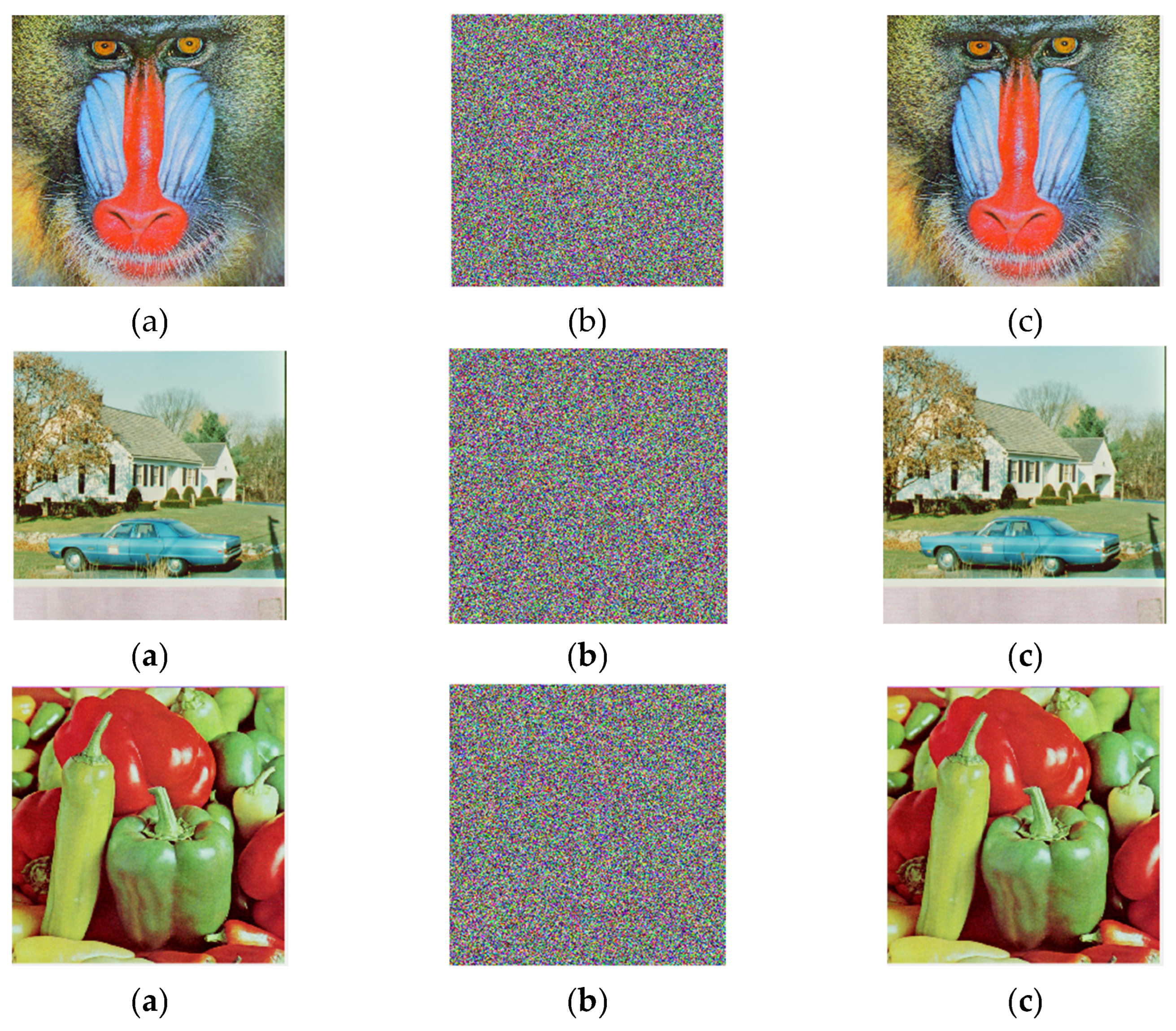
4.5. Experimental Results

The encryption and decryption of baboon, house, and peppers were carried out through this encryption system. The results of the encryption and decryption are shown in Figure 11.

5. Performance Analysis of the Encryption System

To evaluate the security of the encryption system, key sensitivity, NPCR (number of pixels change rate), UACI (unified average changing intensity), histogram analysis, correlation analysis, and information entropy were employed in this experiment.

5.1. Secret Key Sensitivity Analysis

In an image encryption system, good key sensitivity should be possessed. To test key sensitivity, only one bit of the key used for each channel is changed, making the altered key differ from the original key by just one bit. After changing one bit in the key space, the encrypted images and difference images of baboon (baboon), peppers (peppers), and house (house) are shown in Figure 12. To measure the difference between two images, the number of pixels change rate (NPCR) and the unified average changing intensity (UACI) defined by Equations (22) and (23) are commonly used as testing tools. The UACI and NPCR of the encrypted images are shown in Table 6 and Table 7, respectively. In Table 8, the performance comparison of NPCR and UACI on baboon images is presented.
N P C R = 1 M × N i = 1 M j = 1 N F ( i , j ) × 100 %
U A C I = 1 M × N i = 1 M j = 1 N | P 1 ( i , j ) P 2 ( i , j ) | 255 × 100 %

5.2. Histogram Analysis

Histogram analysis, a commonly used statistical method in image encryption evaluation, is employed to examine the uniformity of the pixel value distribution in encrypted images. Original images typically exhibit distinct pixel distribution characteristics, with histograms displaying nonuniform structures. In contrast, an ideal encrypted image should have a histogram that is close to uniformly distributed, meaning the occurrence probability of pixels at each gray level is nearly equal, thereby preventing information leakage. The histograms of the three images before and after encryption are shown in Figure 13, Figure 14 and Figure 15, respectively.

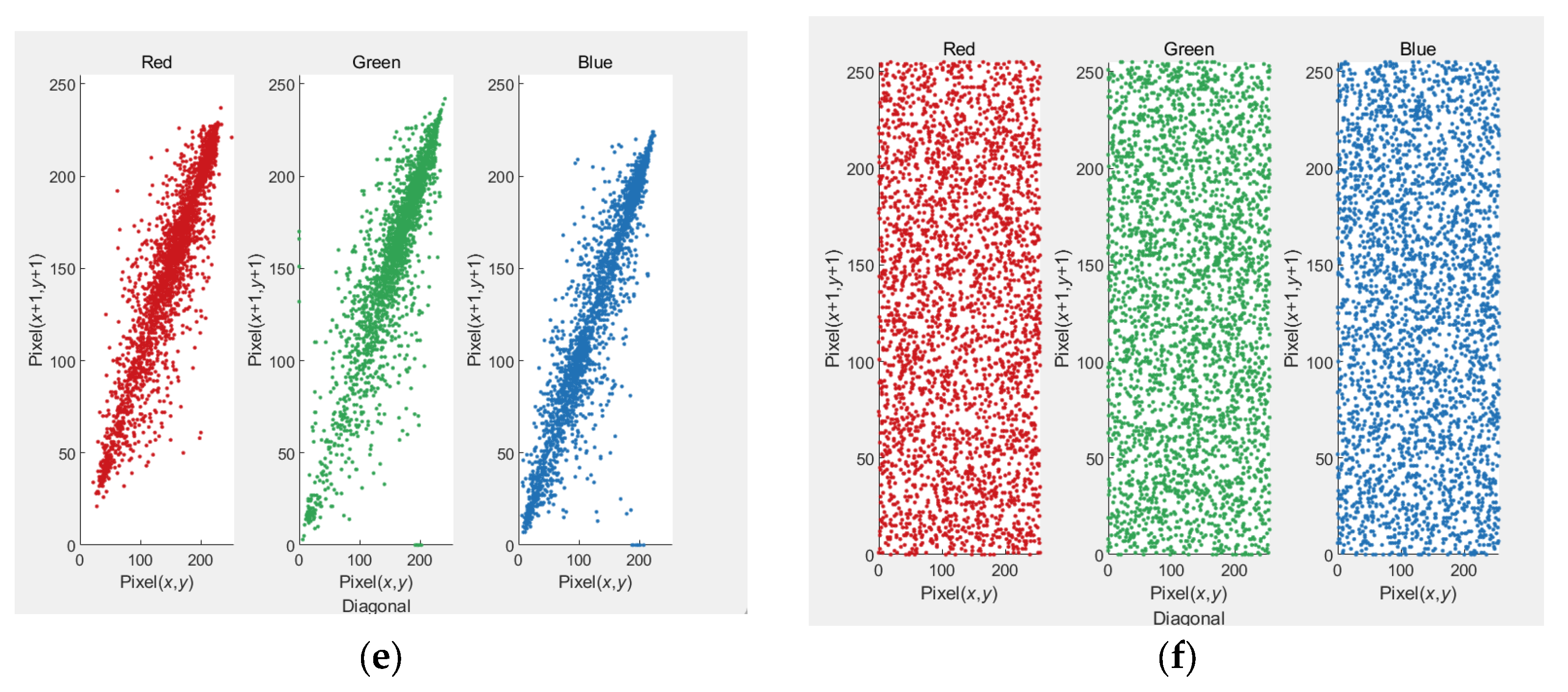
5.3. Correlation Coefficients Analysis

In natural images, due to the coherence of image content, adjacent pixels typically exhibit high correlation. If this property is not effectively disrupted, it can become a vulnerability exploited by attackers. Therefore, an ideal encrypted image should completely break the local correlation of pixels in the original image, resulting in adjacent pixels in the encrypted image having a correlation coefficient close to zero, thereby ensuring that the statistical characteristics of the image are fully concealed. In experiments, a large number of adjacent pixel pairs in the horizontal, vertical, and diagonal directions are usually randomly selected from both the original and encrypted images. The Pearson correlation coefficient is calculated to assess the linear correlation between pixels. The closer the correlation coefficient of the encrypted image is to 0, the more effectively the encryption algorithm disrupts the structural properties of the original image, indicating stronger resistance to statistical attacks.
E ( x ) = 1 K i = 1 K x i
D ( x ) = 1 K i = 1 K ( x i E ( x ) ) 2
C o v ( x , y ) = 1 K i = 1 K ( x i E ( x ) ) ( y i E ( y ) )
r x y = C o v ( x , y ) D ( x ) D ( y )
Through the correlation analysis of the peppers, house, and baboon images before and after encryption in the three channels, as shown in Figure 16, Figure 17 and Figure 18, it can be observed that the three channels of the original images exhibit positive correlation in the horizontal, vertical, and diagonal directions, indicating a clear linear relationship. In contrast, the linear correlation between adjacent pixels in the encrypted images has been significantly weakened or entirely disrupted. Table 9 presents the correlation coefficient and a comparison of the correlation coefficients for the baboon image.

5.4. Information Entropy

Information entropy is an important statistical feature that measures the uncertainty and randomness of pixel distribution in an image and is often used to evaluate the security performance of image encryption algorithms. The image information entropy is shown in Table 10. Its essence is the statistics of the probability of occurrence of grayscale values in an image, which is calculated using the Shannon entropy formula, as follows:
H ( x ) = i = 1 L p ( x i ) log 2 p ( x i ) )

6. Conclusions

This paper proposes a dynamic chaotic image encryption method integrating an improved 2D coupled map lattice (2D CML) and elementary cellular automata (ECA). The method generates the initial chaotic sequence based on a composite logistic–sine map, introduces a nonlinear dynamic coupling coefficient and Arnold mapping to achieve spatial perturbation, and constructs a multi-dimensional collaborative encryption structure. The algorithm employs a three-channel independent encryption mechanism and enhances key space security with SHA-256 hashing. At both the pixel and bit levels, DNA encoding and XOR diffusion mechanisms are used to achieve high-intensity confusion. Experimental results show that the proposed system has high security and efficiency in image encryption. Future research will focus on optimizing the randomness and complexity of chaotic systems, developing adaptive encryption algorithms with deep learning to address complex network environments and quantum computing challenges, and exploring efficient solutions for multi-modal data encryption and hardware implementation.

Author Contributions

X.X. Conceptualization, Validation, Data Curation, Writing—original draft, Writing—review and editing; K.Z. Validation, Writing—review and editing; B.Z. writing—review and editing; H.N. Conceptualization; Y.Z. writing—review and editing; Q.P. writing—review and editing Page 3 of 4; Z.L. Data Curation; All authors have read and agreed to the published version of the manuscript.

Funding

This work was supported by the Hainan Province Science and Technology Special Fund (Fund No. ZDYF2024GXJS034); Hainan Engineering Research Center for Virtual Reality Technology and Systems (Fund No. Qiong fa Gai gao ji [2023] 818); the Innovation Platform for Academicians of Hainan Province (Fund No. YSPTZX202036); the Education Department of Hainan Province (Fund No.Hnky2024ZD-24); the Sanya Science and Technology Special Fund (Fund No. 2022KJCX30).

Data Availability Statement

The Image dataset can be obtained from the following: https://sipi.usc.edu/database/database.php?volume=misc (accessed on 15 March 2025).

Conflicts of Interest

The authors declare no competing interests.

References

  1. Qobbi, Y.; Jarjar, A.; Essaid, M.; Benazzi, A. Image encryption algorithm based on genetic operations and chaotic DNA encoding. Soft Comput. 2022, 26, 5823–5832. [Google Scholar] [CrossRef]
  2. Qobbi, Y.; Jarjar, A.; Essaid, M.; Benazzi, A. Image encryption algorithm using dynamic permutation and large chaotic S-box. Multimed. Tools Appl. 2023, 82, 18545–18564. [Google Scholar] [CrossRef]
  3. Chai, X.; Chen, Y.; Broyde, L. A novel chaos-based image encryption algorithm using DNA sequence operations. Opt. Lasers Eng. 2017, 88, 197–213. [Google Scholar] [CrossRef]
  4. Hua, Z.; Li, J.; Li, Y.; Chen, Y. Image encryption using value-differencing transformation and modified ZigZag transformation. Nonlinear Dyn. 2021, 106, 3583–3599. [Google Scholar] [CrossRef]
  5. Niyat, A.Y.; Hei, R.M.H.; Jahan, M.V. Chaos-based Image Encryption Using a Hybrid Cellular Automata and a DNA Sequence. In Proceedings of the 2015 International Congress on Technology, Communication and Knowledge (ICTCK), Mashhad, Iran, 11–12 November 2015; IEEE: New York, NY, USA, 2015; pp. 247–252. [Google Scholar]
  6. Kaslik, E.; Sivasundaram, S. Nonlinear dynamics and chaos in fractional-order neural networks. Neural Netw. 2012, 32, 245–256. [Google Scholar] [CrossRef]
  7. Iqbal, S.; Wang, J. A novel fractional-order 3-D chaotic system and its application to secure communication based on chaos synchronization. Phys. Scr. 2025, 100, 025243. [Google Scholar] [CrossRef]
  8. Wu, J.; Liu, Z.; Wang, J.; Hu, L.; Liu, S. A compact image encryption system based on Arnold transformation. Multimed. Tools Appl. 2021, 80, 2647–2661. [Google Scholar] [CrossRef]
  9. Bettayeb, M.; Al–Saggaf, U.M.; Djennoune, S. Single channel secure communication scheme based on synchronization of fractional-order chaotic Chua’s systems. Trans. Inst. Meas. Control. 2018, 40, 3651–3664. [Google Scholar] [CrossRef]
  10. Agrawal, S.K.; Srivastava, M.; Das, S. Synchronization of fractional order chaotic systems using active control method. Chaos Solitons Fractals 2012, 45, 737–752. [Google Scholar] [CrossRef]
  11. Iqbal, N.; Hanif, M.; Abbas, S.; Khan, M.A.; Almotiri, S.H.; Al Ghamdi, M.A. DNA strands level scrambling based color image encryption scheme. IEEE Access 2020, 8, 178167–178182. [Google Scholar] [CrossRef]
  12. Kumar, M.; Mohapatra, R.N.; Agarwal, S.; Sathish, G.; Raw, S.N. A new RGB image encryption using generalized Vigenére-type table over symmetric group associated with virtual planet domain. Multimed. Tools Appl. 2019, 78, 10227–10263. [Google Scholar] [CrossRef]
  13. Zhuang, Z.; Zhuang, Z.; Wang, T. Medical image encryption algorithm based on a new five-dimensional multi-band multi-wing chaotic system and QR decomposition. Sci. Rep. 2024, 14, 402. [Google Scholar] [CrossRef] [PubMed]
  14. Zhao, H.; Wang, S.; Wang, X. Fast image encryption algorithm based on multi-parameter fractal matrix and MPMCML system. Chaos Solitons Fractals 2022, 164, 112742. [Google Scholar] [CrossRef]
  15. Niu, Y.; Zhou, Z.; Zhang, X. An image encryption approach based on chaotic maps and genetic operations. Multimed. Tools Appl. 2020, 79, 25613–25633. [Google Scholar] [CrossRef]
  16. Benaissi, S.; Chikouche, N.; Hamza, R. A novel image encryption algorithm based on hybrid chaotic maps using a key image. Optik 2023, 272, 170316. [Google Scholar] [CrossRef]
  17. Zou, C.; Shang, Y.; Yang, Y.; Zhou, C.; Liu, Y. A novel image encryption algorithm with anti-tampering attack capability. Chaos Solitons Fractals 2024, 189, 115638. [Google Scholar] [CrossRef]
  18. Cao, W.; Mao, Y.; Zhou, Y. Designing a 2D infinite collapse map for image encryption. Signal Process. 2020, 171, 107457. [Google Scholar] [CrossRef]
  19. Wang, X.; Liu, P. A new full chaos coupled mapping lattice and its application in privacy image encryption. IEEE Trans. Circuits Syst. I: Regul. Pap. 2021, 69, 1291–1301. [Google Scholar] [CrossRef]
  20. Long, B.; Chen, Z.; Liu, T.; Wu, X.; He, C.; Wang, L.; Cao, C. Improved fractal coding and hyperchaotic system for lossless image compression and encryption. Nonlinear Dyn. 2024, 113, 12233–12262. [Google Scholar] [CrossRef]
  21. Meng, F.Q.; Wu, G. A color image encryption and decryption scheme based on extended DNA coding and fractional-order 5D hyper-chaotic system. Expert Syst. Appl. 2024, 254, 124413. [Google Scholar] [CrossRef]
  22. Yan, X.; Hu, Q.; Teng, L.; Su, Y. Unmanned ship image encryption method based on a new four-wing three-dimensional chaotic system and compressed sensing. Chaos Solitons Fractals 2024, 185, 115146. [Google Scholar] [CrossRef]
  23. Wang, M.; Teng, L.; Zhou, W.; Yan, X.; Xia, Z.; Zhou, S. A new 2D cross hyperchaotic Sine-modulation-Logistic map and its application in bit-level image encryption. Expert Syst. Appl. 2025, 261, 125328. [Google Scholar] [CrossRef]
  24. Jackson, J.; Perumal, R. A novel 2D Hyperchaotic Sine Logistic map based image encryption scheme. J. Opt. 2024, 27, 1–16. [Google Scholar] [CrossRef]
  25. Zhou, K.; Zhang, J.; Xiang, J.; Zhong, Y. Multi-image encryption combining four-dimensional chaotic systems and multi-layer embedding. Eur. Phys. J. Spec. Top. 2024, 233, 1–18. [Google Scholar] [CrossRef]
  26. Wang, X.; Zhao, M.; Feng, S.; Chen, X. An image encryption scheme using bit-plane cross-diffusion and spatiotemporal chaos system with nonlinear perturbation. Soft Comput. 2023, 27, 1223–1240. [Google Scholar] [CrossRef]
  27. Teng, L.; Wang, X.; Yang, F.; Xian, Y. Color image encryption based on cross 2D hyperchaotic map using combined cycle shift scrambling and selecting diffusion. Nonlinear Dyn. 2021, 105, 1859–1876. [Google Scholar] [CrossRef]
  28. Ma, W.; Li, X.; Yu, T.; Wang, Z. A 4D discrete Hopfield neural network-based image encryption scheme with multiple diffusion modes. Optik 2023, 291, 171387. [Google Scholar] [CrossRef]
  29. Zhou, Z.; Xu, X.; Yao, Y.; Jiang, Z.; Sun, K. Novel multiple-image encryption algorithm based on a two-dimensional hyperchaotic modular model. Chaos Solitons Fractals 2023, 173, 113630. [Google Scholar] [CrossRef]
  30. Li, R.; Liu, T.; Yin, J. An encryption algorithm for color images based on an improved dual-chaotic system combined with DNA encoding. Sci. Rep. 2024, 14, 20733. [Google Scholar] [CrossRef]
  31. Wu, X.G.; Wang, K.S.; Wang, X.Y. Color image dna encryption using NCA map-based CML and one-time keys. Signal Process 2018, 148, 272–287. [Google Scholar] [CrossRef]
  32. Wu, X.; Kurths, J.; Kan, H. A robust and lossless dna encryption scheme for color images. Multimed. Tools Appl. 2018, 77, 12349–12376. [Google Scholar] [CrossRef]
  33. Suri, S.; Vijay, R. A synchronous intertwining logistic map-DNA approach for color image encryption. J Amb Intel Hum Comp 2019, 10, 2277–2290. [Google Scholar] [CrossRef]
  34. Praveenkumar, P.; Amirtharajan, R.; Thenmozhi, K.; Rayappan, J.B. Fusion of confusion and diffusion: A novel image encryption approach. Telecommun. Syst. 2017, 65, 65–78. [Google Scholar] [CrossRef]
  35. Machkour, M.; Saaidi, A.; Benmaati, M.L. A novel image encryption algorithm based on the two-dimensional logistic map and the latin square image cipher. 3D Res. 2015, 6, 36. [Google Scholar] [CrossRef]
  36. Chai, X.L.; Gan, Z.H.; Yuan, K.; Lu, Y.; Chen, Y.-R. An image encryption scheme based on three-dimensional Brownian motion and chaotic system. Chin. Phys. B 2017, 26, 020504. [Google Scholar] [CrossRef]
  37. Ismail, S.M.; Said, L.A.; Radwan, A.G.; Madian, A.H.; Abu-Elyazeed, M.F. Generalized double-humped logistic map-based medical image encryption. J. Adv. Res. 2018, 10, 85–98. [Google Scholar] [CrossRef]
  38. Chen, J.; Han, F.; Qian, W.; Yao, Y.-D.; Zhu, Z.-L. Cryptanalysis and improvement in an image encryption scheme using combination of the 1D chaotic map. Nonlinear Dyn. 2018, 93, 2399–2413. [Google Scholar] [CrossRef]
  39. Ye, G.; Zhao, H.; Chai, H. Chaotic image encryption algorithm using wave-line permutation and block diffusion. Nonlinear Dyn. 2016, 83, 2067–2077. [Google Scholar] [CrossRef]
  40. Chai, X. An image encryption algorithm based on bit level Brownian motion and new chaotic systems. Multimed. Tools Appl. 2017, 76, 1159–1175. [Google Scholar] [CrossRef]
  41. Zhang, Y.; Tang, Y. A plaintext-related image encryption algorithm based on chaos. Multimed. Tools Appl. 2018, 77, 6647–6669. [Google Scholar] [CrossRef]
Figure 1. How each cell in the elementary cellular automaton is updated based on its own state and the states of its left and right neighbors from the previous time step, under periodic boundary conditions.
Symmetry 17 01042 g001
Figure 2. Two-dimensional dynamic perturbation matrix.
Symmetry 17 01042 g002
Figure 3. Dynamic neighbor coupling points via Arnold mapping.
Symmetry 17 01042 g003
Figure 4. Obtaining (4N-2)-bit binary via two applications of the Arnold map.
Symmetry 17 01042 g004
Figure 5. (a) Bifurcation diagram of the 2D CML system, (b) bifurcation diagram of the 2D NLCML system, (c) bifurcation diagram of the 2D MCPML system, and (d) bifurcation diagram of the system proposed in this paper.
Symmetry 17 01042 g005
Figure 6. (a) 2D CML, (b) 2D NLCML, (c) 2D MCPML, and (d) KS entropy density of the system proposed in this paper.
Symmetry 17 01042 g006
Figure 7. (a) 2D CML and (b) the system proposed in this paper.
Symmetry 17 01042 g007
Figure 8. (a) Correlation analysis of the 2D CML and (b) correlation analysis of the system proposed in this study.
Symmetry 17 01042 g008
Figure 9. Encryption flowchart.
Symmetry 17 01042 g009
Figure 10. 2D pixel scrambling process based on sorting index.
Symmetry 17 01042 g010
Figure 11. The encrypted and decrypted images of baboon, house, and peppers are shown, respectively. (a) is the original image, (b) is the encrypted image, and (c) is the decrypted image.
Symmetry 17 01042 g011
Figure 12. The encrypted images before and after changing one bit of the key space for baboon, peppers, and house and the difference images. In which, (a) is the image that needs to be encrypted, (b) is the encrypted image, (c) is the image encrypted after changing one bit in the key space, and (d) is the difference image between the encryption results before and after changing the key space.
Symmetry 17 01042 g012
Figure 13. Histogram of baboon image before and after encryption. (a) is the histogram of each channel before encryption, and (b) is the histogram of each channel after encryption.
Symmetry 17 01042 g013
Figure 14. Histogram of the house image before and after encryption. (a) is the histogram of each channel before encryption, and (b) is the histogram of each channel after encryption.
Symmetry 17 01042 g014
Figure 15. Histogram of peppers image before and after encryption. (a) is the histogram of each channel before encryption, and (b) is the histogram of each channel after encryption.
Symmetry 17 01042 g015
Figure 16. A graph showing the correlation of the three peppers channels in the horizontal, vertical, and diagonal directions.
Symmetry 17 01042 g016aSymmetry 17 01042 g016b
Figure 17. Shows the correlation analysis of the three channels of the house in the horizontal, vertical, and diagonal directions.
Symmetry 17 01042 g017aSymmetry 17 01042 g017b
Figure 18. A graph showing the correlation analysis of the three channels of the baboon in the horizontal, vertical, and diagonal directions.
Symmetry 17 01042 g018
Table 1. Rule 60.
Table 1. Rule 60.
Neighbor Combinations111110101100011010001000
next state00111100
Table 2. Rule 105.
Table 2. Rule 105.
Neighbor Combinations111110101100011010001000
next state01101001
Table 3. Rule 150.
Table 3. Rule 150.
Neighbor Combinations111110101100011010001000
next state10010110
Table 4. 8 DNA coding rules.
BinaryRule1Rule2Rule3Rule4Rule5Rule6Rule7Rule9
00ATCGATCG
01TCGAGATC
10CGATTCGA
11GATCCGAT
Table 5. Pseudocode of encryption algorithm in this paper.
Algorithm 1: Image Encryption and Decryption
Input: Original image, user key;
Output: Encrypted image, decrypted image;
1: [h, w, ~] ← size(img)
2: dw_num ← 64
3: N ← dw_num * dw_num//Calculate the number of pixels per block
4: total_pixels ← h * w//Calculate the total number of pixels in the image
5: iterate_num ← ceil(total_pixels/N)//Calculate the required number of iterations for processing
6: fprintf(‘Chaos iterations set to: % d\n’, iterate_num)//Display the number of iterations
7: key ← Input key
8: hash_bits ← GenerateHashBits(key, 4000)//Generate hash bits from the key
9: Split hash_bits into R, G, B parts
10: Initialize chaotic parameters for each channel//Prepare chaotic parameters for encryption
11: for c ← 1 to 3 do
12: [control_u, initial_LOG, iten_e] ← ExtractParams(r_part)//Extract parameters needed for the chaotic system
13: chaos_params(c)← {control_u, initial_LOG, iten_e}//Store the parameters
14: end for
15: encrypted_img ← zeros(size(img), ‘uint8’)//Initialize the encrypted image matrix
16: shuffle_indices ← Cell array//Prepare a cell array to store shuffle indices(processed X)
17: xor_keys ← Cell array//Prepare a cell array to store XOR keys(processed Y)
18: processed_z_sequences ← Cell array//Prepare a cell array to store processed Z sequences
19: for c ← 1 to 3 do//Encrypt each channel
20: Generate chaotic sequence//Generate the chaotic sequence for the current channel
21: Shuffle pixel positions//Shuffle the positions of pixels in the current channel
22: XOR diffusion//Perform XOR diffusion on the pixel values
23: DNA encoding//Apply DNA encoding to enhance encryption
24: encrypted_img ← Reshape encrypted data//Reshape and store the encrypted data in the encrypted image
25: end for
26: Save encrypted image
27: Read the user input key (key).
28: Use the key to generate hash bits (hash_bits) = GenerateHashBits(key, 4000), generating hash bits of length 4000.
29: Divide the generated hash bits into three parts, corresponding to the red (R), green (G), and blue (B) channels.//Split hash bits into parts for each channel
30: Initialize chaotic parameters for each channel.//Prepare chaotic parameters for decryption
31: for c ← 1 to 3 do
32: [control_u, initial_LOG, iten_e] ← ExtractParams(r_part)
33: chaos_params(c) ← {control_u, initial_LOG, iten_e}
34: end for
35: decrypted_img ← zeros(size(img), ‘uint8’)//Initialize the decrypted image matrix
36: for c ← 1 to 3 do//Decrypt each channel
37: DNA decoding//Reverse DNA encoding to restore pixel values
38: Reverse XOR diffusion//Reverse XOR diffusion to recover original pixel values
39: Restore pixel positions//Restore the original positions of pixels
40: decrypted_img← Reshape decrypted data//Reshape and store the decrypted data in the decrypted image
41: end for
Table 6. UACI of baboon, house, and peppers.
ImageUACIRGB
Baboon33.4284%33.4543%33.4034%33.4275%
House33.4400%33.4217%33.4576%33.4408%
Peppers33.5341%33.5681%33.4705%33.5637%
Table 7. NPCR of baboon, house, and peppers.
ImageNPCRRGB
Baboon99.6078%99.6132%99.5995%99.6109%
House99.6003%99.6147%99.5934%99.5930%
Peppers99.6146%99.6056%99.6235%99.6147%
Table 8. Performance comparison of NPCR and UACI on baboon images.
AlgorithmNPCR (%)UACI (%)
Proposed Algorithm99.607833.4284
Ref. [34] 99.581932.0972
Ref. [35]99.800033.3700
Ref. [36]99.620033.4400
Ref. [37] 75.500033.4520
Ref. [38]99.598033.1420
Ref. [39]99.615033.4020
Table 9. Correlation coefficient and comparison of the baboon image correlation coefficient.
ImageAlgorithmCorrelation Direction
HorizontalVerticalDiagonal
BaboonProposed Algorithm−0.00230.00090.0021
HouseProposed Algorithm−0.0039−0.00360.0028
PeppersProposed Algorithm−0.00180.0004−0.0032
HouseProposed Algorithm−0.0007−0.00290.0020
BaboonRef. [34]0.0030−0.00620.0046
BaboonRef. [35]0.0021810.0019280.002138
BaboonRef. [36]0.00570.000050480.0024
BaboonRef. [40]0.0013−0.02810.0128
BaboonRef. [41]−0.0142−0.04460.0106
Table 10. Image information entropy.
ImageAlgorithmCorrelation Direction
RedGreenBlue
HouseProposed Algorithm7.98957.99017.9887
BaboonProposed Algorithm7.99157.99137.9914
PeppersProposed Algorithm7.99167.99177.9914
HouseProposed Algorithm7.99157.99117.9913
LenaRef. [33]7.98927.98987.9899
LenaRef. [34]7.98957.98947.9894
LenaRef. [35]7.97587.98227.9419
Disclaimer/Publisher’s Note: The statements, opinions and data contained in all publications are solely those of the individual author(s) and contributor(s) and not of MDPI and/or the editor(s). MDPI and/or the editor(s) disclaim responsibility for any injury to people or property resulting from any ideas, methods, instructions or products referred to in the content.

