Abstract
Nowadays, electric motors are an integral part of most modern electromechanical systems that are used in industry. It follows that industrial processes are becoming more dependent on their efficiency. If faults in electric motors are not rectified, they can lead to malfunctions and accidents, as well as production downtime. Symmetry of a three-phase system means that the voltage and current in the three phase conductors are equal to each other, with a period of 120°. Asymmetry occurs if one of these conditions or both conditions are violated at the same time. In most cases, asymmetry is caused by loads. Predictive diagnostics is the most effective way to identify motor faults while the motor is in operation and prevent the likelihood of failure. Predictive diagnostics can identify problems that could lead to major failures, thus reducing production downtime and maintenance costs. The paper discusses the control and diagnosis of electric motors using prediction techniques. In particular, the use of neural network models and predictive control to improve accuracy and reliability is investigated. The main objective of this research is to develop a neural network controller based on predictive model predictive control (MPC), which will improve the quality of the control and diagnostics system of electric motors, ensuring their stability and preventing possible malfunctions.
1. Introduction
Modern industrial production is undergoing rapid transformation under the influence of digitalization [1,2], the development of sensor technologies, and the integration of artificial intelligence methods [3]. The reliability and efficiency of equipment remain key requirements, as even short-term downtime can lead to significant financial losses and disruption of technological processes. Electric motors, forming the basis of most electromechanical systems, are increasingly used in advanced applications such as electric vehicles [4,5,6], robotics, and automated production lines, where their performance directly determines the overall system efficiency and reliability [7,8].
Traditional control and diagnostics approaches, while still widespread, often do not provide the necessary level of adaptability and early fault detection [9], especially in the context of growing complexity and variability of operating conditions [10,11].
If the three-phase voltage is unbalanced, there will be reverse-sequence current and a reverse-sequence magnetic field in the motor, which will create more reverse-sequence torque, resulting in an unbalanced three-phase motor current distribution and increased phase winding current. When the three-phase voltage asymmetry reaches 5%, the motor phase current can exceed 20% of the normal value. Three-phase voltage asymmetry is mainly manifested as the following:
- Anomalies occurring in one phase of a three-phase transformer winding transmitting an unbalanced supply voltage.
- Long transmission lines, with an unequal wire cross-section size and different impedance voltage drop, resulting in unbalanced voltage in each phase.
- When power supply and lighting have a common, mixed, single-phase load, such as for the following—household appliances, electric furnaces, welding machines, etc.—and are too concentrated in a single or two phases, this results in unequal load distribution of each phase, so that the supply voltage and current are imbalanced.
The emergence of predictive maintenance and model predictive control (MPC) technologies marks a new stage in the evolution of industrial automation. Predictive diagnostics, based on machine learning and artificial neural networks, enables the forecasting of equipment states, detection of anomalies [1], and proactive intervention before critical failures occur [8]. The integration of MPC with diagnostic systems allows for real-time consideration of operational constraints (such as current and voltage limits), which minimizes the risk of overheating, overloading, and extends the service life of electric motors [12,13]. Various control methods, including deadbeat predictive control, have been developed to enhance PMSM drive performance [14,15,16,17,18].
Recent studies demonstrate the effectiveness of combining advanced sensor systems [19], machine learning algorithms (including ARIMA, Random Forest, and LSTM), and data-driven approaches for monitoring and controlling electric motors in industrial environments [8]. The use of bluetooth and high-speed data acquisition systems, as well as the implementation of hybrid control structures, are becoming industry standards in the context of Industry 4.0.
Moreover, the development and implementation of such hybrid solutions require in-depth modeling and tuning [20], including the use of artificial neural networks to improve prediction accuracy and control quality [21]. The relevance of this direction is confirmed by recent publications in leading scientific journals, which highlight the growing role of predictive models and digital technologies in ensuring the reliability and efficiency of modern control systems.
Thus, the creation of integrated systems that combine predictive diagnostics and model predictive control is a promising and urgent task, aimed at improving the quality of control [22,23,24], reducing response time to deviations, and ensuring the reliable operation of equipment in modern industrial enterprises.
2. Materials and Methods
2.1. Predictive Control Method in Electric Motor Diagnostics
The MPC-based control system works efficiently due to regular input of measurements of object parameters such as current, voltage, speed and evaluation of their compliance with target values that consider the history of previous states (Figure 1). The controlled parameters are calculated in such a way as to ensure minimal deviations from the target values while remaining within the set limits, which is particularly important for stable and safe operation of the motor (Figure 2). In this case, a computer model developed in the Python 3.13 programming language is investigated.
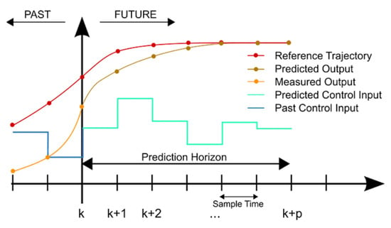
Figure 1.
Regulator structure based on predictive control model.
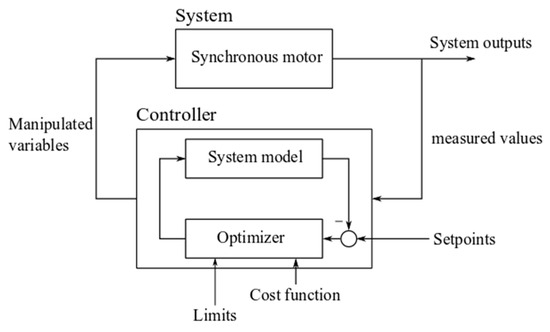
Figure 2.
Structure of control system with controller based on predictive control model [compiled by authors].
The current voltage and shaft speed parameters can also be compared by the MRS controller in the process of evaluating the current state of the motor. If deviations from optimum operation are detected, the controller takes corrective action, preventing possible failures, reducing the risk of overloads, and extending the life of the equipment. This ensures higher reliability and efficiency of the equipment.
One of the key benefits of MPC is its ability to predict future system states, allowing potential faults to be detected early. By predicting potential abnormalities and automatically correcting them, the MPC controller minimizes risk and downtime, improving overall system performance and reliability. MPC also adapts to changes in system parameters and external conditions, making it a flexible and efficient tool for industrial applications [1,9,20].
However, despite its high efficiency, MPC has its limitations. Complex mathematical models are required to achieve high prediction accuracy, and their implementation and tuning often require significant computational resources and time. Powerful hardware is often required to perform operational calculations, which can increase implementation costs. In addition, the development and calibration of such systems can be technically challenging, especially for applications with rapidly changing parameters or multi-tasking processes.
2.2. Modeling of Electric Motor Control System
In this paper, a permanent magnet synchronous motor is chosen as a test model. Since current control minimizes resistance losses and reduces drive heating, the observed parameters are the stator current and voltage, which determine the overall system efficiency. These parameters not only directly affect the energy efficiency of the motor, but also ensure optimal thermal behavior, prevent premature wear, and increase the long-term reliability of the equipment [24].
To simplify the control, the separation of the current components into d (i_sd) and q (i_sq) axes is used (Figure 3). The i_sd current controls the magnetic flux of the motor, which affects the induction of the windings, while the i_sq current is responsible for generating the electromagnetic torque, allowing more precise and flexible control of the drive operation. In three-phase electric motors, control is achieved by applying voltages to three stator windings, which are usually designated as phases a, b and c.
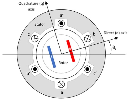
Figure 3.
Axes d and q with respect to the rotor [compiled by authors].
This separate control improves the dynamic response of the system, reduces power consumption and guarantees stable motor operation even under varying loads and operating conditions [4,25].
The Python 3.13 programming language was used to model the control system; ‘numpy’ and ‘matplotlib’ are libraries designed for mathematical calculations and visualization; ‘gym-electric-motor’ is a library for motor simulation and algorithm testing; ‘GEKKO’ is a module to increase the accuracy of calculations and optimize the process (Figure 4).
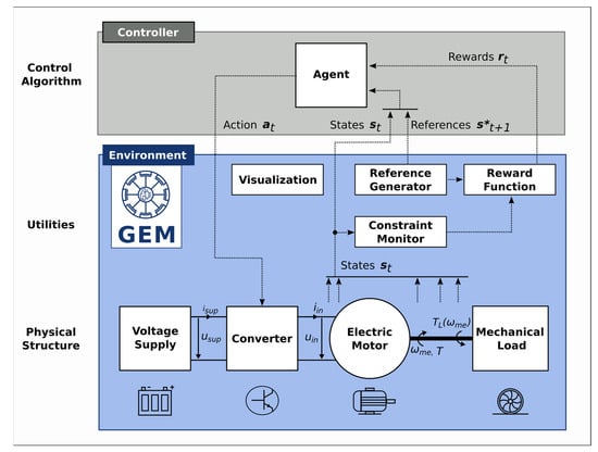
Figure 4.
Interface of the library for motor modeling and algorithm testing ‘gym-electric-motor’ of the Python programming language [compiled by the authors].
In addition, the use of these tools accelerated prototyping and analysis of the system behavior in different operating scenarios, which greatly improved the efficiency of development.
Plotting the graphs showed how key parameters change during motor operation: the standard deviation function, the nominal and actual current value in each axis relative to the magnet rotor axis, and the voltage in both axes.
The negative standard deviation function (MSE) was chosen as the reward function:
where n = 2, Y1 and Y2 are the axis current values, and Ŷ1 and Ŷ2 are the target axis current values.
Ua, Ub, and Uc are the voltages that are applied to the stator windings and control the motors. The controller must influence the motor by precisely adjusting these voltages to maintain stable operation and achieve the required performance. The simulation was carried out under uniform motor load conditions with angular velocity ω = 301,000/π radians/s for one second. The simulation analyzed the response of the system to changes in control parameters and determined the optimum settings to maximize the efficiency and stability of the motor operation [26,27,28].
For the initial evaluation of the system, a test without a controller was run, which showed that the motor parameters quickly exceed the acceptable limits, leading to system failure (failures are marked by red vertical lines in the graph) (Figure 5).
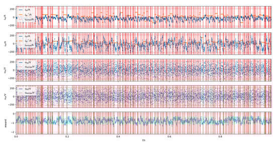
Figure 5.
Simulation results of system without controller [compiled by authors].
This confirms the need to control parameters using controllers to prevent failures.
Modeling using PID controllers: Three PID controllers were added to the model: two for each current axis and one for speed control. Figure 6 shows the changes in key parameters of the engine control system over time. Analysis of the graph shows that the use of PID controllers has stabilized the engine operation, preventing sharp fluctuations in parameters. PID controllers successfully prevent parameters (such as current and voltage) from going beyond acceptable limits. The use of PID controllers has led to an improvement in the overall assessment of the system (which was −869 points), indicating an increase in the efficiency and reliability of the engine.
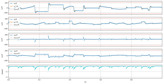
Figure 6.
Results of system modeling with PID controllers [compiled by authors].
Modeling using FOC controller: Field-oriented controllers (FOCs) are designed to control the currents of synchronous motors. For continuous variables, the control is performed in rotary coordinates dq, and the two current components are handled separately by two independent controllers, one controlling the motor flux and the other the torque. For discrete controlled variables, control is performed in stator coordinates and the controlled variables are calculated separately for each current component [29,30].
In the simulation, the FOC controller is used in combination with vertical and horizontal PID controllers to maintain the current components at the required levels. As a result, the final score is −552.9, which is an improvement. Figure 7 shows that oscillations occur only at transition points; the rest of the time the system is in a steady state.
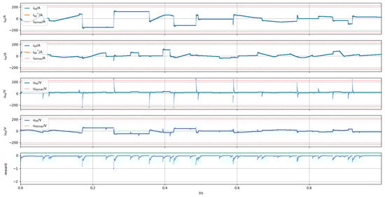
Figure 7.
Simulation results of system with FOC controller [compiled by authors].
Use of predictive controller (MPC): The predictions of the developed MPC controller are based on the history of changes in the system parameters. Constraint-based control is achieved using the controller, which in turn allows the controller to calculate the control for a given number of steps [5,14,31].
The initial state of the controller is based on the boundary values of the motor parameters, and the main algorithm is realized in the ‘control’ function. In this function, the current state of the system is compared with the target values and the error function is optimized to minimize the deviation; using the Python library ‘GEKKO’, control variables (u_d, u_q) can be generated, converted into phase voltages, normalized and corrected according to the constraints.
A five-step prediction horizon was chosen to test the MPC controller. The results showed a final score of −626, which is lower than previous experiments (Figure 8).
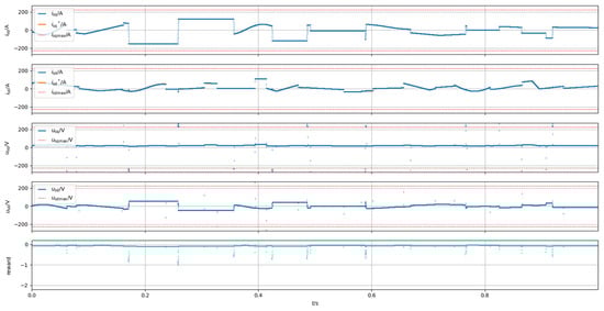
Figure 8.
Simulation results of system with MPC controller [compiled by authors].
At the same time, MPC demonstrated faster system stability recovery and shorter transient time. This makes the predictive controller a promising solution for motor control under varying load conditions and the need for precise control [15,16].
2.3. Theoretical Basis for Predictive Control: MPC Mathematical Apparatus and Its Applications
Model Predictive Control (MPC) is a powerful control method based on mathematical prediction and optimization. This type of controller is used to control complex systems, such as electric motors, which require a high degree of accuracy and adaptability. The MPC controller concept uses a model of an object to predict its future behavior. Control actions are then optimized to minimize deviations from the target state, considering the system constraints.
Mathematical model of MPC controller. The application of MPC to an electric motor control system starts with the construction of a mathematical model. This model describes its dynamic behavior through a system of equations containing current, voltage, speed, and torque parameters. A linear model can be used as the simplest model. But to ensure higher accuracy, nonlinear models are often used because they allow the relationship between different motor parameters to be considered [17,18].
Suppose that the motor control system is described by a linear discrete equation:
where χκ is the state vector at step k, uκ is the control action, [A] and [B] are matrices describing the dynamic behavior of the system.
The application of MPC will minimize the objective function and find the optimal values of u to keep the system within the given constraints.
Optimization methodology: To compute the control process in MPC and find the solution in real time, iterative optimization methods are widely used: the Lagrangian and gradient descent methods. Depending on the nature of the system and the complexity of the target, an optimization method is chosen [6,19]. The Lagrangian method can be used to solve optimization problems with constraints, in this case on voltage or current. Lagrange multipliers are calculated to determine the constraints on the variables and allow the MPC to calculate the control signals given the system constraints. The gradient descent method can be applied to the cost function minimization problem by iteratively adjusting the control parameters in the anti-gradient direction. This method is relevant when the model is nonlinear and more complex algorithms are difficult to use. Quadratic Programming (QP) methods contain QP algorithms that are often used in linear and quadratic systems. These algorithms provide efficient solution search by introducing quadratic target functions and linear constraints. QP can compute control actions with high speed, so its use is relevant in real-time applications.
When controlling an electric motor, the use of MPC controller is conditioned by the necessity to keep the current and speed parameters within the specified limits. This condition will reduce wear and tear and extend the life of the equipment. Under varying load conditions, MPC significantly improves the stability and efficiency of electric motor operation due to its predictive properties and correction of the system behavior [32,33]. The use of MPC in electric motor control provides fast response to parameter deviations, prevention of overloads and overheating, and an efficiency improvement due to dynamic adaptation of control actions in real time.
We have added an experimental flowchart (Figure 9). for robustness analysis, introduced parameter uncertainty, determined stability using Lyapunov methods, and finally revised the parameters of the MPC algorithm.
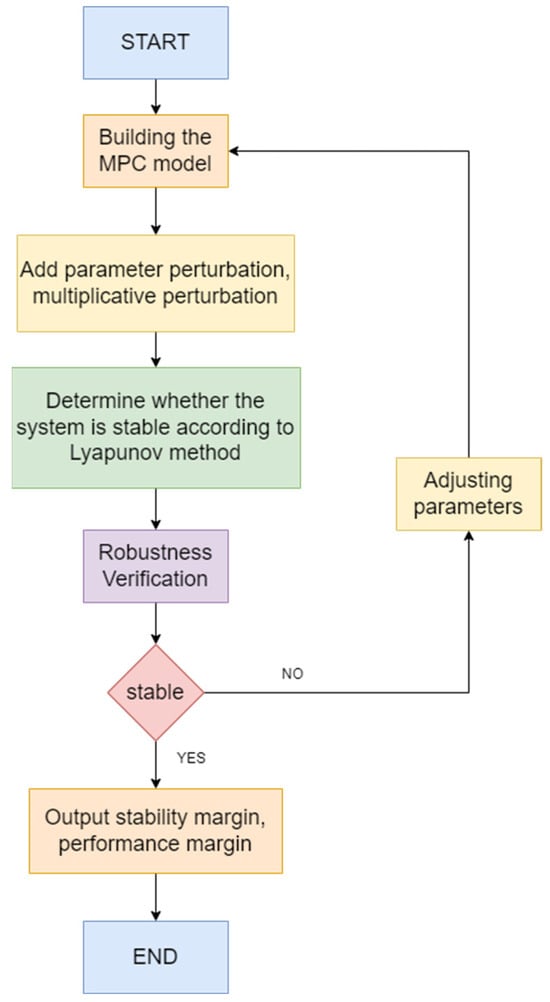
Figure 9.
Flowchart for robustness analysis.
3. Research and Discussion
Modeling an MPC controller based on a neural network: LSTM (Long Short-Term Memory) is a recurrent neural network architecture designed to efficiently capture and utilize long-term dependencies in data (Figure 10 and Figure 11).
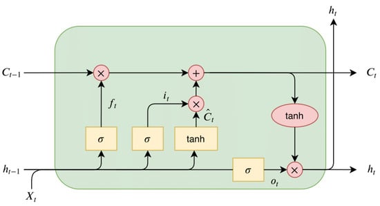
Figure 10.
LSTM cell architecture [compiled by authors].
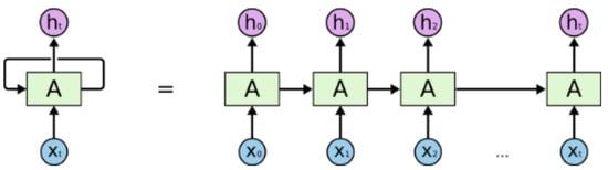
Figure 11.
Recurrent neural network (RNN) deployment [compiled by the authors].
First proposed in 1997, LSTM has subsequently been improved and adapted for various tasks where time sequences need to be considered [34].
The main advantage of LSTMs over traditional recurrent neural networks is that they avoid the problems of fading and gradient discontinuity, which makes them ideal for dealing with time-dependent data. These elements allow LSTMs to efficiently store and update information over long time intervals, making them suitable for control tasks such as motor control, where it is important to consider the sequence of parameter measurements and their time dependence (Figure 12). LSTMs are well suited for this control task. This is because motor control requires considering the sequence of measurements of different parameters over time, and LSTMs can store and utilize this information efficiently. In practical applications, the controller can be implemented using either the STM32H7 series or a DSP + FPGA combination. Both solutions offer excellent real-time performance and can support neural networks and time-sensitive control algorithms. For example, the STM32H743 model features 1 MB of Flash memory, 512 KB of RAM, and operates at a 480 MHz clock frequency.
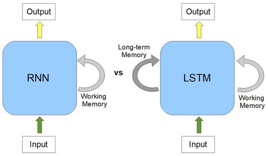
Figure 12.
Features of RNN and LSTM architecture [compiled by authors].
The hybrid model used in this paper combines two layers: LSTM and a full-channel layer (Figure 13). This type of architecture is used to build the controller interface. In this case, the current state of the motor and target parameters are taken as input, and control signals are output by the controller [2,35].
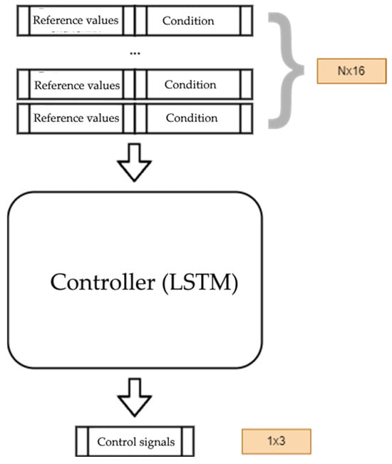
Figure 13.
Interface of the developed model [compiled by the authors].
The gym-electric-motor library models electric motors with complex nonlinear dynamics, complicating direct fault backpropagation. To address this, we developed an integrated LSTM-based controller coupled with a motor behavior neural network. The LSTM structure of the controller allows for efficient handling of time dependencies and system dynamics, which is important for accurate control of nonlinear processes. On the other hand, the neural network learns from the engine performance data and simulates its behavior under different operating conditions. This combination allows for more accurate prediction and tuning of system performance, considering complex interactions and optimizing real-time control (Figure 14).
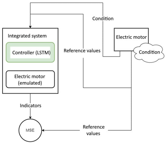
Figure 14.
Stages of neural network training [compiled by the authors].
The model, which is based on an LSTM controller and a neural network to simulate motor operation, defines the initial conditions. The neural network is pre-trained to accurately reproduce the characteristics of the real motor and to support the error back propagation process. The target value of the drive current is then determined [3,36,37].
Model architecture: three hidden layers with 128 units each, trained for 1 k to 6 k iterations.
The neural network parameters are fine-tuned through backpropagation based on motor-model error minimization.
In the article, we employed a substantial amount of simulated data, as it serves as an excellent preliminary validation tool for algorithms before proceeding to actual testing on permanent magnet synchronous motors (PMSMs).
In practical systems, compensated Hall sensors or shunt resistors are typically used to measure the current in PMSMs. For the controller, options include the STM32H7 series or a DSP + FPGA combination. The STM32H7 series, with RAM ranging from 500 KB to 1 MB, is fully capable of meeting the computational demands of the neural networks discussed in the article.
On the other hand, FPGAs can directly implement hardware-level tasks such as PWM generation, encoder decoding, and ADC synchronization, achieving nanosecond-level latency. Meanwhile, the DSP can focus on high-level algorithms (e.g., FOC or neural networks) without being burdened by low-level timing tasks. This combination of DSP and FPGA can also effectively integrate neural networks as controllers for PMSMs.
The integrated model is trained in the specified order:
The parameters of the current state of the system in the form of current values from the modeled motor are transmitted to the controller.
In the process of comparing the received current values and target parameters, control signals are generated by the LSTM controller.
The signals are then applied to the modeled motor, allowing its operation to be adjusted to the target values.
The difference between the target and actual current values is calculated using the Mean Square Error (MSE) function:
To minimize the deviations, an error back propagation algorithm is used to adjust the parameters of the integrated model (Figure 15). Training iterations: 3–5 k (3000 to 5000), with a training set size of 1.5 GB. It can be seen from the figure that the error decreases from 1.5 k iterations and becomes almost zero after 3 k iterations.
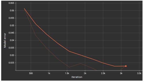
Figure 15.
Graph of error during motor model training [compiled by authors].
Next, the controller model is trained. The results of verification during the training process are shown in Figure 16. On the validation set, the error decreased rapidly within the first 1000 iterations, then oscillated around 5% thereafter.
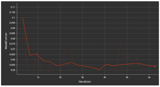
Figure 16.
(Reviewer 1) Error graph during controller model training [compiled by authors].
Figure 17 shows the simulation results of the MPC controller (Table 1), which is based on a neural network. The total reward was −480.7. This value surpasses the performance achieved by other types of controllers that have been used to control this system. The developed controller allows to effectively predict and correct the behavior of the electric motor, maintain its operation within the set parameters and significantly reduce deviations compared to classical controllers. During neural network training, cross-validation was employed to effectively prevent model overfitting. The vertical axis of the graph represents the motor’s dq-axis voltage, dq-axis current, and the obtained score, while the horizontal axis denotes time (in seconds).
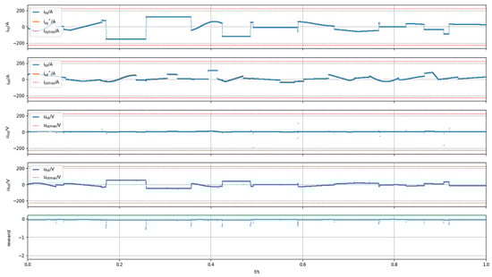
Figure 17.
Simulation results using neural network-based MPC model [compiled by authors].

Table 1.
Comparative analysis of simulation results when using different types of controllers [compiled by authors].
The scores in the table were updated by averaging the results from multiple experiments. Regarding load change conditions, our LSTM-enhanced model predictive control (MPC) achieved a settling time of 50 ms, which is 40% faster than traditional PID controllers. (When the controlled plant is a permanent magnet synchronous motor (PMSM), the neural network must be retrained to adapt to the motor parameters. Conversely, if the controlled plant is not a PMSM, both the control method and the neural network model architecture need to be modified accordingly.
4. Conclusions
This study analyzed existing predictive motor control systems including classical MPC controllers and neural network-based controllers. The process of motor design and modeling has been studied. The peculiarities of design of both a traditional controller and predictive controller based on trained elements of artificial neural network are considered. The article also presents the results of testing and comparative analysis of the effectiveness of the proposed controllers, which, in turn, allows us to objectively assess their advantages and disadvantages. A model that is too small may fail to converge, while an excessively large model can compromise real-time performance. Therefore, the model should be compact yet convergent to ensure fast response speeds and lower computational demands. Additionally, the controller’s processing speed significantly impacts overall responsiveness. Hence, during model training, we prioritize minimizing the model size while achieving optimal control performance.
The conducted tests showed that the predictive controller based on the neural network has 24% less control error compared to the traditional algorithmic controller and almost two times less error than the PID controller. In addition, the developed predictive controller showed faster response speed, which is an important advantage in situations requiring immediate intervention and fine tuning. The experimental results showed that the predictive controller provides more stable and reliable control, effectively preventing possible emergency situations and ensuring optimal motor operation within the specified parameters.
The obtained results confirm the high accuracy of the controller model and its ability to solve the predictive control problems. This makes the developed motor control and predictive diagnostics system based on neural network approach a valuable tool for improving safety and efficiency of industrial electric motors.
The present study makes a significant contribution to the field of predictive diagnostics and control by providing a promising solution for monitoring and predicting the condition of an electric motor. Improved performance can be achieved by applying more sophisticated multilayer LSTM models and other neural network architectures. These can be convolutional neural networks (CNNs) to extract spatial features and recurrent neural networks (RNNs) to better handle temporal dependencies. Future research is proposed to investigate the possibility of using these models to improve prediction accuracy and control robustness, as these types of networks allow the system to consider a wider range of factors and dynamic processes. It is also planned to integrate reinforcement learning techniques to provide adaptability and self-regulation of the system under changing external influences and uncertainty. This will allow optimization of the motor control process in more complex and unstable operating conditions.
Author Contributions
Conceptualization, Y.K.; methodology, D.N.; software, Y.K. and D.N.; validation, E.M.; formal analysis, E.M.; investigation, E.K.; resources, Y.K.; data curation, Y.Y. and Y.K.; writing—original draft, E.M. and Y.Y. All authors have read and agreed to the published version of the manuscript.
Funding
This research received no external funding.
Data Availability Statement
The original contributions presented in the study are included in the article; further inquiries can be directed to the corresponding author/s.
Conflicts of Interest
The authors declare no conflicts of interest.
Abbreviations
The following abbreviations are used in this manuscript:
| DWA | Dynamic Window Method |
| JBFS | Greedy Best-First Search |
| RRT | Rapidly exploring Random Tree |
References
- Makhovikov, A.B.; Filyasova, Y.A. Digital technologies in the extraction of solid minerals in the Arctic. Sustain. Dev. Mt. Territ. 2024, 16, 1110–1117. [Google Scholar] [CrossRef]
- Huang, S.-D.; Chen, L.; Cao, G.-Z.; Wu, C.; Xu, J.; He, Z. Predictive Position Control of Planar Motors Using Trajectory Gradient Soft Constraint with Attenuation Coefficients in the Weighting Matrix. IEEE Trans. Ind. Electron. 2021, 68, 821–837. [Google Scholar] [CrossRef]
- Qiu, D.; Qiu, D.; Wu, B.; Gu, M.; Zhu, M. Hierarchical Control of Trajectory Planning and Trajectory Tracking for Autonomous Parallel Parking. IEEE Access 2021, 9, 94845–94861. [Google Scholar] [CrossRef]
- Vasiliev, B.Y.; Kozyaruk, A.E.; Mardashov, D.V. Increasing the utilization factor of an autonomous inverter under space vector control. Russ. Electr. Eng. 2020, 91, 247–254. [Google Scholar] [CrossRef]
- Zhang, W.; Shen, Y.; Mao, J. A Nine-Phase Permanent Magnet Electric-Drive-Reconstructed Onboard Charger for Electric Vehicle. IEEE Trans. Energy Convers. 2018, 33, 2091–2101. [Google Scholar] [CrossRef]
- Rovere, L.; Formentini, A.; Zanchetta, P. FPGA Implementation of a Novel Oversampling Deadbeat Controller for PMSM Drives. IEEE Trans. Ind. Electron. 2019, 66, 3731–3741. [Google Scholar] [CrossRef]
- Krestovnikov, K.D.; Cherskikh, E.O.; Saveliev, A.I. Investigation of the influence of the length of the intermediate magnetic circuit on the characteristics of magnetic gripper for robotic complexes of the mining industry. J. Min. Inst. 2020, 241, 46–52. [Google Scholar] [CrossRef]
- Lvov, V.V.; Aleksandrova, T.N.; Kuskov, V.B.; Pelevin, A.E. Study of possibility of magnetic hydrocyclone use in concentration cycles of oxidized ferriferous quartzites. CIS Iron Steel Rev. 2022, 23, 4–8. [Google Scholar] [CrossRef]
- Manap, M.; Nikolovski, S.; Skamyin, A.; Karim, R.; Sutikno, T.; Jopri, M.H. An analysis of voltage source inverter switches fault classification using short time fourier transform. Int. J. Power Electron. Drive Syst. 2021, 12, 2209–2220. [Google Scholar] [CrossRef]
- Chen, H.; He, J.; Demerdash, N.A.O.; Guan, X.; Lee, C.H.T. Diagnosis of Open-Phase Faults for a Five-Phase PMSM Fed by a Closed-Loop Vector-Controlled Drive Based on Magnetic Field Pendulous Oscillation Technique. IEEE Trans. Ind. Electron. 2021, 68, 5582–5593. [Google Scholar] [CrossRef]
- Niu, S.X.; Luo, Y.X.; Fu, W.N.; Zhang, X.D. An indirect reference vector-based model predictive control for a three-phase PMSM motor. IEEE Access 2020, 8, 29435–29445. [Google Scholar] [CrossRef]
- Minakova, T.E.; Malarev, V.I.; Korzhev, A.A. Method to identify operating regimes of asynchronous drivers by subharmonic parameters in mining. Min. Inf. Anal. Bull. 2022, 11, 96–108. [Google Scholar] [CrossRef]
- Beloglazov, I.; Plaschinsky, V. Development MPC for the Grinding Process in SAG Mills Using DEM Investigations on Liner Wear. Materials 2024, 17, 795. [Google Scholar] [CrossRef]
- Hao, Z.; Zhu, H.; Cheng, Y.; Huang, L. Speed Control of Bearingless Permanent Magnet Synchronous Motor Based on Flux Strengthening and Voltage Regulation. IEEE Access 2018, 6, 72392–72401. [Google Scholar] [CrossRef]
- Sun, X.; Zhang, Y.; Cai, Y.; Tian, X. Compensated deadbeat predictive current control considering disturbance and VSI nonlinearity for in-wheel PMSMs. IEEE/ASME Trans. Mechatron. 2022, 27, 3536–3547. [Google Scholar] [CrossRef]
- Dai, S.; Wang, J.; Sun, Z.; Chong, E. Multiple Current Harmonics Suppression for Low-Inductance PMSM Drives with Deadbeat Predictive Current Control. IEEE Trans. Ind. Electron. 2022, 69, 9817–9826. [Google Scholar] [CrossRef]
- Kakosimos, P.; Abu-Rub, H. Deadbeat Predictive Control for PMSM Drives with 3-L NPC Inverter Accounting for Saturation Effects. IEEE J. Emerg. Sel. Top. Power Electron. 2018, 6, 1671–1680. [Google Scholar] [CrossRef]
- Sun, X.; Cao, J.; Lei, G.; Guo, Y.; Zhu, J. A robust deadbeat predictive controller with delay compensation based on composite sliding mode observer for PMSMs. IEEE Trans. Power Electron. 2021, 36, 10742–10752. [Google Scholar] [CrossRef]
- Sun, X.; Shi, Z.; Cai, Y.; Lei, G.; Guo, Y.; Zhu, J. Driving-cycle oriented design optimization of a permanent magnet hub motor drive system for a four-wheel-drive electric vehicle. IEEE Trans. Transp. Electrif. 2020, 6, 1115–1125. [Google Scholar] [CrossRef]
- Sharikov, Y.V.; Snegirev, N.V.; Tkachev, I.V. Development of a control system based on predictive mathematical model of the C5-C6 isomerization process. J. Chem. Technol. Metall. 2020, 55, 335–344. [Google Scholar]
- Korolev, N.A.; Zhukovskiy, Y.L.; Buldysko, A.D. Energy Resource Evaluation from Technical Diagnostics of Electromechanical Devices in Minerals Sector Mining Informational and Analytical Bulletin. 2024. No. 5. pp. 158–181. Available online: https://giab-online.ru/en/catalog/ocenka-energeticheskogo-resursa-na-osnove-diagnostiki-tehnichesk (accessed on 6 May 2025).
- Sychev, Y.A.; Zimin, R.Y. Improving the quality of electricity in the power supply systems of the mineral resource complex with hybrid filter-compensating devices. J. Min. Inst. 2021, 247, 132–140. [Google Scholar] [CrossRef]
- Vorontsov, A.G.; Glushakov, V.V.; Pronin, M.V.; Sychev, Y.A. Cascade frequency converters control features. J. Min. Inst. 2020, 241, 37–45. [Google Scholar] [CrossRef]
- Firouzi, N.; Rabczuk, T.; Bonet, J.; Żur, K.K. A computational framework for large strain electromechanics of electro-visco-hyperelastic beams. Comput. Methods Appl. Mech. Eng. 2024, 426, 116985. [Google Scholar] [CrossRef]
- Jiménez Carrizosa, M.; Stankovic, N.; Vannier, J.; Shklyarskiy, Y.E.; Bardanov, A.I. Multi-terminal dc grid overall control with modular multilevel converters. J. Min. Inst. 2020, 243, 357–370. [Google Scholar] [CrossRef]
- Sun, X.; Xu, N.; Yao, M.; Cai, F.; Wu, M. Efficient feedback linearization control for an IPMSM of EVs based on improved firefly algorithm. ISA Trans. 2023, 134, 431–441. [Google Scholar] [CrossRef]
- Zhao, W.; Wang, X.; Gerada, C.; Zhang, H.; Liu, C.; Wang, Y. Multi-Physics and Multi-Objective Optimization of a High Speed PMSM for High Performance Applications. IEEE Trans. Magn. 2018, 54, 1–5. [Google Scholar] [CrossRef]
- Rassõlkin, A.; Kallaste, A.; Orlova, S.; Gevorkov, L.; Vaimann, T.; Belahcen, A. Re-Use and Recycling of Different Electrical Machines. Latv. J. Phys. Tech. Sci. 2018, 55, 13–23. [Google Scholar] [CrossRef]
- Sun, X.; Xu, N.; Yao, M. Sequential subspace optimization design of a dual three-phase permanent magnet synchronous hub motor based on NSGA III. IEEE Trans. Transport. Electrif. 2023, 9, 622–630. [Google Scholar] [CrossRef]
- Sun, X.; Cao, Y.; Jin, Z.; Tian, X.; Xue, M. An adaptive ECMS based on traffic information for plug-in hybrid electric buses. IEEE Trans. Ind. Electron. 2023, 70, 9248–9259. [Google Scholar] [CrossRef]
- Shi, Z.; Sun, X.; Cai, Y.; Yang, Z.; Lei, G.; Guo, Y.; Zhu, J. Torque analysis and dynamic performance improvement of A PMSM for EVs by skew angle optimization. IEEE Trans. Appl. Supercond. 2019, 29, 1–5. [Google Scholar] [CrossRef]
- Degli-Esposti, V.; Fuschini, F.; Bertoni, H.L.; Thomä, R.S.; Kürner, T.; Yin, X.; Guan, K. IEEE Access Special Section Editorial: Millimeter-Wave and Terahertz Propagation, Channel Modeling, and Applications. IEEE Access 2021, 9, 67660–67666. [Google Scholar] [CrossRef]
- Hu, Y.; Deng, Y.; Liu, Q.; He, X. Asymmetry Three-Level Gird-Connected Current Hysteresis Control with Varying Bus Voltage and Virtual Oversample Method. IEEE Trans. Power Electron. 2014, 29, 3214–3222. [Google Scholar] [CrossRef]
- Zhang, X.; Wang, Y.; Yu, C.; Guo, L.; Cao, R. Hysteresis Model Predictive Control for High-Power Grid-Connected Inverters with Output LCL Filter. IEEE Trans. Ind. Electron. 2016, 63, 246–256. [Google Scholar] [CrossRef]
- Li, Y.; Ruan, X.; Wang, Y.; Zhang, C. Hysteresis Voltage Prediction Control for Multilevel Converter in the Series-Form Switch-Linear Hybrid Envelope Tracking Power Supply. IEEE Trans. Power Electron. 2020, 35, 13663–13672. [Google Scholar] [CrossRef]
- Karnauhov, A.M.; Kozhubaev, Y.; Ilin, A.E.; Ivanov, V.V. Controlling of the digital transformation oil and gas industry//XI International Scientific and Practical Conference Innovative Technologies in Environmental Science and Education (ITSE-2023). E3S Web Conf. 2023, 431, 05031. [Google Scholar] [CrossRef]
- Kozhubaev, Y.; Ruide, Y. Simulation of Dynamic Path Planning of Symmetrical Trajectory of Mobile Robots Based on Improved A* and Artificial Potential Field Fusion for Natural Resource Exploration. Symmetry 2024, 16, 801. [Google Scholar] [CrossRef]
Disclaimer/Publisher’s Note: The statements, opinions and data contained in all publications are solely those of the individual author(s) and contributor(s) and not of MDPI and/or the editor(s). MDPI and/or the editor(s) disclaim responsibility for any injury to people or property resulting from any ideas, methods, instructions or products referred to in the content. |
© 2025 by the authors. Licensee MDPI, Basel, Switzerland. This article is an open access article distributed under the terms and conditions of the Creative Commons Attribution (CC BY) license (https://creativecommons.org/licenses/by/4.0/).